1
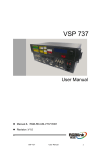
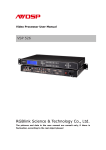
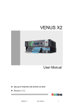
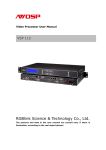
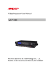
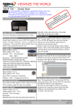
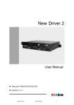
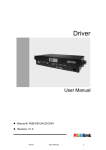
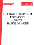
User Manual
CP 1024
RGBlink Science & Technology Co.,Ltd.
The pictures and data in the user manual are reference only, if there is any
modification, please check the real device!
CONTACT US
Addresss: S603 Weiye Building Torch Hi-Tech Industrial Development Zone
Xiamen,Fujian Province, P.R.C
Tel: +86-592-5771197
Fax:+86-592-5771202
E-mail:[email protected]
http://www.rgblink.com
http://www.rgblink.cn
File version
version
time
1.0
2011-11-21
ECO#
0000
Description
Release
principal
CONTENT
1.0 Safety .......................................................................................................................1
2.0 Specification ............................................................................................................2
3.0 Connection ...............................................................................................................2
3.1 CP 1024 connectors and signals........................................................................2
3.2 CP 1024 Size and installation ...........................................................................3
4.0 Control Panel Operation ..........................................................................................4
4.1 CP 1024 Operator Guideline.............................................................................4
4.2 CP 1024 Video Processor Menu .......................................................................9
5.0 Appendix ................................................................................................................23
5.1 Appendix I Download CP 1024 IP software ...................................................23
6.0 Quick User Guide ..................................................................................................25
6.1 Device connection...........................................................................................25
6.2 Instruction for control panel............................................................................27
1.0 Safety
The general safety information in this summary is for operating person. Any
requirement, please feel freely to contact our service engineer.
Power Source
This product is intended to operate from a power source
between 85~265 volts rms . This product is only workable under
correct power condition, which is already mark on the back panel
of the power.
High Voltage
There are many high voltage components inside.
Do not Remove Covers and Panels
Do not remove Covers in any conditions. There are not any
spare components inside for maintenance, so do not maintain
this product by userrselves, any requirement, please feel free to
contact our service engineer. Keep heavy device from power
cord.
Grounding the Product and Use the Proper Fuse
This product is grounded through the grounding conductor of
the power cord. To Avoid electrical shock, plug the power cord
into a properly wired receptacle before connecting to the product
input or output terminals.
Keep away from Magnet, Motor, TV and Transformer.
Guard Against Damp
Keep using inside clean and dryness environment, once the
device get wet, must remove power cord right now.
Keep away Exploder
Do not operate the device inside dangerous and easy
explosive gas, which it may make fire, blast or something without
expectation.
Keep away Pour Liquid and Fragment
It is forbid to pour liquid, metal fragment or anything else
inside this device to avoid fire and other accident. Once that
happens, must remove power cord and try to make it clean
before power on again.
CP 1024 User Manual
Doc No:RGB-RD-UM-CP1024C001
1
2.0 Specification
CP 1024, works as the control panel for VSP 729, support an easy going user
interface for control, and it can control more than one VSP 729 through network,
RS232. it’s ideal for stage performances, conferencing system, school, church
or other live application. With features simple operation panel, the
multi-function joystick operation, T-bar switch, the dynamic display on LCD, and
gooseneck lamp for low-light environment.
3.0 Connection
3.1 CP 1024 connectors and signals
1、Mini switch, more details please refer to Appendix II
2、RJ45, used to connect the computer by 568B-568A twist-pair;
3、USB, used to work with AVDSP Console PC software;
4~7、RS232 interface (RJ11) for VSP processor. Used to connect the computer;
8~11、Switch and power. It must use IEC-3 power line. Always ground to avoid
electric shock.
CP 1024 User Manual
Doc No:RGB-RD-UM-CP1024C001
2
3.2 CP 1024 Size and installation
CP 1024 User Manual
Doc No:RGB-RD-UM-CP1024C001
3
4.0 Control Panel Operation
Insert power cord and push power button to ON position.LCD module on the
front panel will show RGBLINK and go into self verification before it load the last
setting config and send the processed image to the target monitor. For the first
time, CV1 input is the default input source. With the control panel, users can
operate the equipment with menu displayed on LCD module.
4.1 CP 1024 Operator Guideline
Followed picture of front Panel Keyboard
LED light, gooseneck lamp for low-light environment. (Optional accessory)
Menu operation:
LCD module: display the menu for button operation and communication.
Knob switch: Used to adjust the options on the LCD menu, slightly rotate the
knob to set the LCD options or option values.
ESC: push to exit from current choice item;
SEL: Push to confirm the current choice item;
Video input layer 1 2 3 4: Signal input area, used for four input channel signal
CP 1024 User Manual
Doc No:RGB-RD-UM-CP1024C001
4
selection of VSP729: CV1,CV2,CV3,CV4,CV5,CV6,CV7,CV8,VGA1,VGA2,
VGA3,VGA4,DVI1,DVI2,DVI3,DVI4 signal input switch buttons, push the
button to switch the signal input.
ensure the correct input signal access while switching。
PROGRAM:
1:Channel 1, indicative key light, push the button to display image of this
channel.
2:Channel 2, indicative key light, push the button to display image of this
channel.
3:Channel 3, indicative key light, push the button to display image of this
channel.
4:Channel 4, indicative key light, push the button to display image of this
channel.
BG: Background channel switches, indicative key light, push the button to
display image of this channel.
PREVIEW:
1:Preview channel 1,indicative key light, push the button to display image
of this channel.
2:Preview channel 2,indicative key light, push the button to display image
of this channel.
3:Preview channel 3,indicative key light, push the button to display image
of this channel.
4:Preview channel 4,indicative key light, push the button to display image
of this channel.
BLK:Black field switch, indicative key light, push the button to display
image of this channel.
CP 1024 User Manual
Doc No:RGB-RD-UM-CP1024C001
5
Mode1:Single-window mode, push the button, Program ouput would be display
in single picture, on the control panel, one of the 1, 2, 3, 4 buttons will light,
ready to send to the program output, it supports switching with 1,2,3,4 windows
in preview with seamless effects.
Mode2:Dual-window mode, push the button,program ouput would be display
in dual pictures, on the control panel, 1 and 2 buttons will light,ready to send
to the program output, it supports switching with 3 and 4 in preview with
seamless effects.
Mode3:Triple-window mode, push the button,program ouput would be display
in triple pictures, on the control panel, 1,2,3 buttons will light,ready to send to
the program output, it supports switching with 4 in preview with seamless
effects.
Mode4:Quad-window mode, push the button,ogram ouput would be four
pictures, In the console Program, 1,2,3,4 buttons will light,namely output
channel lights.
Image adjust:
Joystick: used to set XYZ coordinates. Push Joystick in horizontal will shift the
horizontal position or size, push Joystick in vertical will shift the vertical position
or size, push Z order will change the windows size in horizontal and vertical at
the same time.
Scale:scale button push to on will make Joystick to work in window size scale
mode;lightly push the joystick to the left or up, image length and width will be
reduced, lightly push the joystick to the right or down, image length and width
will be increased.
Pos: position button push to on will make Joystick to work in window position
shift mode; lightly push the joystick to the left or up, image horizontal or vertical
position will be reduced, lightly push the joystick to the right or down, image
horizontal or vertical position will be increased.
CP 1024 User Manual
Doc No:RGB-RD-UM-CP1024C001
6
(Scale): Zoom adjusted starting point on bottom of right corner,
zooming starts from the right and bottom
(Pos): image coordinates of upper corner on the left is (0,0),
Pos adjust starts from upper corner on the left
Mutil control:
V1:Push to the button to light, supports control the first VSP 729
V2:Push to the button to light, supports control the second VSP 729
V3:Push to the button to light, supports control the third VSP 729
V4:Push to the button to light, supports control the fourth VSP 729
Control method could be RS232 seriel port on the rear panel, or 10/100M
network control interface, connecting to the router through a different IP
address to those VSP 729 (V1 control VSP729 IP addresss:192.168.0.100;V2
control
VSP729
IP
address:192.168.0.101 ; V3
control
VSP729
IP
address:192.168.0.102;V4 control VSP729 IP address:192.168.0.103,VSP729
default IP address: 192.168.0.100,IP address could be changed by VSP729 PC
Software)
Custom function:
SAVE: Save button, push this button, all Save1~Save10 will light, all the
setting and parameters were saved to one of Save1~Save10, choose one of
them, push the button till light off, saving was done.
LOAD: push the button, all Save1~Save10 in the program and preview
will light, choose one of them, push the button till light off, loading successed.
User could switch between user mode, data would load within 1 second.
Default saving mode SAVE1 data would loading automatically
when turn on the device.
Matrix:matrix button, push this button till light on, 1234 of program and
1234 of preview will work as matrix. E.g. in mode 3, three-channel mode, push
martix till light on, to make two of the images the same, you need to push 3 of
program, and 1 of the preview, channel 1 would be copy to channel 3, push
CP 1024 User Manual
Doc No:RGB-RD-UM-CP1024C001
7
SAVE to confirm, and save to SAVE 1 mode so as to load the data in the future.
LOCK: Lock button, push this button till light on, all buttons light, which
were locked, operation is invalid, press LOCK again till light off, all buttons are
unlocked, operation come to valid again.
TAKE: Effects switch button, push this button, to switch with fading and
sepcial effects between program and preview channels.
Effect switch bar:Effect switch bar, push up or down gently to do fade
switch between program channel and preview channel, bar pushing could stop
anywhere to make two images
superimposed.
Seamless switch:
:fading button, push this button to light on, pressing TAKE or pushing
effect bar to do fading switch.
:Seamless direct switch, push this button to light on, pressing TAKE to
do fading switch.
:Left curtain switch, push this button to light on, pressing TAKE to do
curtain switch.
:Right curtain switch, push this button to light on, pressing TAKE to do
curtain switch.
:Down curtain switch, push this button to light on, pressing TAKE to do
curtain switch.
:Up curtain switch, push this button to light on, pressing TAKE to do
curtain switch.
: wipe center out in vertical, push this button to light on, pressing TAKE
to do curtain switch.
:wipe center out in horizontal, push this button to light on, pressing
TAKE to do curtain switch.
CP 1024 User Manual
Doc No:RGB-RD-UM-CP1024C001
8
: wipe plus out. push this button to light on, pressing TAKE to do curtain
switch.
4.2 CP 1024 Video Processor Menu
Menu has two parts, the above part is to display real-time information, the
bottom part is for operation, as shown below:
Operation information on display
The following information would be displayed on screen: output resolution of
the processor in control, fading time, effect switch speed, logo switch, black
filed switch, test pattern switch, brightness value, Color temperature value,
Saturation value, sharpness value, contrast value, aspect ration value, position
of X and Y coordinates, width and height of image, input channel, input signal
information, input format, etc.
Operation menu part
Menu as below:
RGBLINK
视诚科技
控台系列
AVCPP Series CP 1024
CP 1024 User Manual
Doc No:RGB-RD-UM-CP1024C001
9
Wait Init Network…
When the device runs, the factory IP address displays on it as shown
IP Address
192.168.0.10
After system connection was completed with the first device, it will display
as shown
Connect device
V1
IP:192.168.0.100
After the device connection was successfully completed, the system goes
into prompt state as shown:
V1
Connect
IP:192.168.0.100
success
When device fails in connection, the system goes into prompt state as
shown:
V1
IP:192.168.0.100
Connect
failed
After device fails in connection, check that if the device was well connected,
if VSP729 IP address is correct
Please refer to VSP729 User Manual if you want to correct the
VSP729 IP address
After the program runs, the system main menu appears as below:
>CP 1024
*Dev Info
Reset
Swirling the knob to select the menu on the left or right, with means option
was selected, push SEL to enter into menu setting or checking
Device name CP 1024 was displayed on it, select Dev Info and press SEL to
CP 1024 User Manual
Doc No:RGB-RD-UM-CP1024C001
10
display the relative signal information of inputs and outputs
As shown:
Program 1:DVI
1920x1080x60
Swirling the knob to check the preview input:
Preview 2:VGA
1024x768x60
Swirling the knob to check the output format:
Output Format:
1024x768x60
Swirling the knob to check the version of the program:
Software Version
0.8
Swirling the knob to check the device serial No., user need it for asking for
more effective service and support
RGBLINK
SN:CP1234
Push ESC, go back to main menu as below. Swirling the knob to Recall to do
factory reset
>CP 1024
Dev Info
*Reset
Push SEL to do factory reset to VSP729 programmed, after factory reset
finished, LCD module display as below:
Reset Finished
Push SEL to exit the menu, system main menu as below, turn the menu to
next page, user could set language in 【LANGUAGE】option.
>CP 1024
*Language
CP 1024 User Manual
OUT
Doc No:RGB-RD-UM-CP1024C001
11
Push SEL to enter into the sub-menu setting, 【LANGUAGE】 sub-menu as
below:
* Language select
> English
中文
Swirling knob to selected LCD display language, push SEL to confirm.
Push ESC, exit the main menu, swirling the knob, select OUT to set output
>CP 1024
Language
OUT
Push SEL to enter into the sub-menu, Program menu as below:
OUT
>Program
Preview
Push SEL to enter into the sub-menu; sub-menu of Program:
PROGRAM
>DE setup
HDMI/DVI
Push SEL to enter into the sub-menu, DE setup sub-menu as followed:
PROGRAM
>ON
DE
ON/OFF
Select 【ON】, push SEL to enter into DE setup menu, swirling to set
parameter of the option:
> PROGRAM
*35
DE H Start
Or scrolling down the menu as below:
> PROGRAM
> 35
DE H Start
> PROGRAM
> 35
DE V Start
> PROGRAM
> 35
DE Width
CP 1024 User Manual
Doc No:RGB-RD-UM-CP1024C001
12
> PROGRAM
> 35
DE Height
DE H Start: horizontal coordinate set of the image; DE V Start: vertical
coordinate set of the image;
DE Width: width set of the image; DE Height: height set of the image, push
ESC, go back to the previous menu, swirling the knob, select HDMI/DVI to
enter into output signal protocol setting:
PROGRAM
DE setup
>HDMI/DVI
Push SEL to enter into sub menu of HDMI/DVI output, do setting to the
output signals. Select the HDMI output or DVI output. (HDMI output support
HDMI1.3, DVI output support DVI1.0), as shown:
PROGRAM
>HDMI
HDMI/DVI
In the same way, Preview output setting could be done.
Push ESC, go back to main menu of 【MENU】, swirling to scroll down to
device time setting:
>CP 1024
*Time
Calendar
Push SEL to enter into Time setting
Time
> 00:00:20
Push SEL to active time setting, * appears on the left, the changeable option
is flashing, swirling to adjust the value:
Time
*00:00:20
Push ESC, go back to the previous menu, swirling to set the calendar:
> CP 1024
Time
CP 1024 User Manual
* Calendar
Doc No:RGB-RD-UM-CP1024C001
13
Push SEL to enter into 【Calendar】 setting, date displayed on the left side
of calendar,
the day of week on the right:
Calendar
>2010/01/01
Sun
Push SEL to active date setting, * appears on the left of time, the
changeable option is flashing, swirling to change the flashing date and day of a
week:
Calendar
*2010/01/01
Sun
Push ESC, go back to the main menu, swirling to scrolling down the【MENU】
to 【Scale】setting:
> CP 1024
* Scale
Advance
Push SEL to set Scale, Scale menu includes the following options:
Scale Width: vertical size setting
Scale Width CH2:
>1024
Scale Height: horizontal size setting:
Scale Height CH2:
>768
Scale Pos X: horizontal coordinate setting
Scale Pos X CH2:
>0
Scale Pos Y: vertical coordinate setting:
Scale Pos Y CH2:
>0
Scale is to set the program outputs, preview keeps always
fullscreen display. Above image displays CH2, means currently
CH2 is working, bar could control it directly.
CP 1024 User Manual
Doc No:RGB-RD-UM-CP1024C001
14
User could easily change the image size and position by setting parameters on
the right side of the screen.
Push ESC, go back to main menu, swirling the bar to do advanced setting,
including screen parameter settings, aspect ratio setting, switching the preview
mode setting, output resolution settings, V1V2V3V4IP address settings.
> CP 1024
Scale
* Advance
Push SEL to enter screen parameter settings of the Advanced Menu: screen
parameter is the image display area setting, the image would fulfil the screen
after correct setting, The width, height, X position and Y position are adjustable:
Screen width :
>1024
Screen height :
>1024
Screen pos X :
>1024
Screen pos Y :
>1024
Aspect ratio setting in advanced menu:
Normal video aspect ratio:4:3 and 16:9(Width to Height), swirling the bar to
switch from two different ratios.
preview and switch mode
setting: set display mode after Preview image
switched.
Exchange: after Take button or T-bar switch, image from program and preview
would be displayed in exchange
Follow: after Take button or T-bar switch, program follows preview, it displays
the same output image.
Preview switch mode:
>Exchange
CP 1024 User Manual
Doc No:RGB-RD-UM-CP1024C001
15
Preview switch mode:
>Follow
Default mode is exchange Preview switch mode
Advanced menu output resolution setting: Set VSP729 output resolution,
VSP729 has five output resolutions: 800*600@60 , 1024*768@60 ,
1280*768@60,1600*1200@60,1920*1080@60
output resolution:
>800*600@60
Change output resolution by swilring the knob
Advanced
menu
V1V2V3V4IP
address
, push SEL to confirm.
setting:
It’s
adjustable
to control VSP729 IP address, to control multi VSP729
with different IP address, control range from 192.168.0. 1 to 192.168.0. 254,
except for 192.168.0.10.
V1
IP:192.168.0.100
Eg: Four units VSP 729, the first IP address is 192.168.0.100. the
second 192.168.0.101 the third 192.168.0.102 and the forth
192.168.0.103. After setting V1 could control the IP address of
192.168.0.100
to
make
the
first
VSP729
controlled,
set
IP
of192.168.0.102 controlled by V1 to make the third VSP729
controlled, 192.168.0.102.
Push ESC, go back to main menu, swirling the bar to scroll down the
page,set the【Picture】;
> CP 1024
*Picture
CP 1024 User Manual
BG
Doc No:RGB-RD-UM-CP1024C001
16
Push SEL, enter into Picture setting, image quality options as below:
Set Brightness: brightness setting, to change the image brightness.
Set Contrast: Contrast settings, image color contrast can be changed by
contrast settings;
Set Saturation: color temperature settings,
change color temperature by
settings the color temperature value;
Set Red Color: red color set, the image can be changed by red color setting
Set Green Color: green color set, the image can be changed by green color
setting
Set Blue Color: blue color set, the image can be changed by blue color setting
User could do setting according to their requirements, the function are for
professionals, non-specialists were not suggested to use it, mistakes can lead
to distortion of image quality, they could use Iinitialize and factory reset.
Push ESC, go back to the main menu, swirling to set【BG】background.
> CP 1024
Picture
* BG
Background
*Black
VIN0
BG setting menu:
Swirling the bar to set the background, black means black background, VINO is
the background input
Background input image resolution is the same with output
Push ESC, go back to the main menu, swirling the bar to scrolling down the
【MENU】, 【AB Mode】 effect switching is adjustable:
> CP 1024
*AB Mode
CP 1024 User Manual
Crop
Doc No:RGB-RD-UM-CP1024C001
17
【AB Mode】including: full screen switch, transparent full screen switch,
curtain switch, transparent curtain switch.
curtain switch and transparent curtain switch offers six different switch
methods, one is with soft a transparent effect, image moves to the right, to the
left, down, up, wipe in vertical and wipe in horizontal,
Swirling to select the curtain switch in AB Mode, it could make curtain
effects:(CUT Switch)opaque image switch moving to the right, image moving
to right, image scrolling down, image scrolling up, image quartet switch, wipe in
the horizontal and wipe in vertical and DISSOVLE Switch with transparent
switch.
Setup AB Mode
> CUT Switch
Setup AB Mode
> DISSOVLE Switch
WIRE button could also enter into AB Mode, to set effect switch
Push SEL to confirm fading time, swirling knob to set the fading seconds in
the range of “0.5 s-30.0 s”
Dissolve Duration:
>3.0 s
FADE button could also enter into AB Mode, to adjust fading time
Push SEL to enter into WIPE HARD Switch:
Setup AB Mode
> WIPE HARD Switch
Setup AB Mode
> WIPE SOFT Switch
CP 1024 User Manual
Doc No:RGB-RD-UM-CP1024C001
18
Swirling knob to check the several seamless switch modes:
WIPE Mode
> WIPE RIGHT
WIPE Mode
*WIPE LEFT
WIPE Mode
*WIPE DOWN
WIPE Mode
*WIPE UP
WIPE Mode
*WIPE PLUS OUT
WIPE Mode
*WIPE CURTAIN OUT
WIPE Mode
*WIPE CENTER OUT
CP 1024 User Manual
Doc No:RGB-RD-UM-CP1024C001
19
Push ESC, go back to the main menu, swirling the knob to set 【Crop】
capture:
> CP 1024
AB Mode
*Crop
Push SEL to enter into Crop setting, Crop menu including the following options:
Crop
Width:vertical size setting:
CP 1024 User Manual
Doc No:RGB-RD-UM-CP1024C001
20
Crop Width CH2:
>1024
Crop
Height:Horizontal size setting:
Crop Height CH2:
>768
Crop Pos X:horizontal coordinate setting:
Crop Pos X CH2:
>0
Crop Pos Y:vertical coordinate setting:
Crop Pos Y CH2:
>0
Push ESC, go back to the main menu, swirling to turn 【MENU】 to next page ,
【Matrix】 available for adjusting:
CP 1024
*Matrix
TP
Push SEL, enter into Matrix setting, Matrix menu including the following options:
Input Select :CH1
> Input 2
The above image shows: signal from channel 2 copy to channel 1.
Input Select :CH2
> Input 3
The above image shows: signal from channel 3 copy to channel 2.
Select anyone of Preview 1234, through PRG button to do signal
programming, select the source signal to use the matrix function.
Push ESC, go back to the main menu, swirling to set【TP】 test pattern
CP 1024
Matrix
*TP
Push the SEL button to enter TP test pattern setting,,TP test pattern menu as
CP 1024 User Manual
Doc No:RGB-RD-UM-CP1024C001
21
below:
TP Setup
*Program
Preview
Push the SEL button to enter Program TP test pattern setting, Program TP test
pattern menu includes the following options:
Program TP
*ON
OFF
Enter into Preview setting
TP test pattern is Color Bar,resolution is 1024x768x60 。
CP 1024 User Manual
Doc No:RGB-RD-UM-CP1024C001
22
5.0 Appendix
5.1 Appendix I Download CP 1024 IP software
Turn off the power, take the two coding switch to “ON” sate as below:
Connect one side of the RJ11 download line to the RS232 on the video processor,
and the other side to be connected to the serial port on the PC
Double click
:to run flash magic, setting as below:
First, users can choose the right serial port, set the baud rate to 115200, choose
LPC2368, and to load the aim document (hex. document) of inboard upgrading
secondly, confirm the two option box by tick.
CP 1024 User Manual
Doc No:RGB-RD-UM-CP1024C001
23
At last, click the Start button.
When download finished, exit the program, turn off the device, reset the two
dial code (as shown), restart the device, check whether the device work.
Flash Magic Software download link:
http://www.flashmagictool.com/download.html&d=FlashMagic.exe
CP 1024 User Manual
Doc No:RGB-RD-UM-CP1024C001
24
6.0 Quick User Guide
6.1 Device connection
Connect Power cord to the power port, and use the CAT5 cable with the package
to connect between two LAN ports on the CP 1024, or from LAN port of CP 1024
to VSP 729 LAN port. The LAN cable should be crossover cable, which is one end
in T568A, and another end in T568B standard.
If CP 1024 will make communication with VSP 729, the defacult IP address of
VSP 729 is 192.168.0.100.
When communication is OK, push power on button to run the processor, and
check whether all the buttons on the top panel and the LCD is working with the
right menus show as following.
The LAN cable should be crossover cable, which is one end in
T568A, and another end in T568B standard.
If communication is correct, the menu shows Connect success.
V1
IP:192.168.0.100
Connect
success
And when the connection is successful, the buttons and LCD modules will
work as the last user config, take the following picture as reference.
CP 1024 User Manual
Doc No:RGB-RD-UM-CP1024C001
25
If connection is not working, the menu will show Connect failed, check the
communication cable and the power cord in need and also the IP address of the
processor, whether the address is in the same segment.
V1
Connect
IP:192.168.0.100
failed
For modify the IP address, please check with the user manual of
VSP 729.
If
the
communication
is
not
sucessful,
push
V1
button
and check the menu on the LCD module, push SEL
to confirm to communicate the device on LAN, if the communication
setup, it will show success info. Use the same steps to check communication
with V2, V3 and V4.
Check device V1
>YES
NO
Check device V1
success
CP 1024 User Manual
Doc No:RGB-RD-UM-CP1024C001
26
6.2 Instruction for control panel.
The buttons on Video Input Layer 1 is one to one correspond to the back
panel of CP 1024.
This is the same for Layer 2, Layer 3 and Layer 4.
is correspond to the Background
And
connector.
The buttons on the Program position, are used to show the current output
layer or layers. It is not comment to push the button directly to switch the layer.
The program output will send the layer or layers video
from its
port to back end system.
The buttons on the Preview position, are used to show the current output
CP 1024 User Manual
Doc No:RGB-RD-UM-CP1024C001
27
layer or layers. User can push each layer, and use TAKE or CUT to switch the
layer
to the preview output on the back panel
, and with the TAKE or CUT effects, user can see the layer
which is been preview, will be on with the effects on the program output, and the
preview output will show the original program output layer (if user define data
as switch), or keep show current preview layer (if user define data as keep).
There are 4 predefine modes, which are
.
These 4 modes define the program output layer or layers effects. For Mode1, will
output layer in single window, and Mode2 is in Picture in Picture or Picture by
picture, Mode3 is triple pictures, and Mode4 is in Quad. Not matter one picture
or quad ones, user can scale or position each picture with scale or zoom funtion
by Joystick or menu Knob button.
All the user menu system can be access by Knob button
button
and ESC button
>CP 1024
*Dev Info
inside
Menu
Operation
, SEL
position.
Reset
Push SEL button can go into submenu and push ESC button can exit the
current menu.
The buttons inside Seamless Switch position, are used to define the
seamless switch effects during TAKE or T-BAR operation.
. This is
Fade in Fade out effect button, and this is factory default setting button
CP 1024 User Manual
Doc No:RGB-RD-UM-CP1024C001
28
.
The Joystick, SCALE button and POS button are used to do Image
Adjustment.
User push to select SCALE button, and operate with Joystick, will scale the
picture on the program output. Pull Joystick to up position, will zoom out the
picture in vertical, pull down will zoom in the picture in vertical, pull left will
zoom out the picture in horizontal, and pull right will zoom in the picture in
horizontal. Rotate the Joystick in counterclockwise, will zoom out in horizontal
and vertical at the same time, Rotate Joystick in clockwise, will zoom in in
horizontal and vertical at the same time.
.
User push to select POS button, and operate with Joystick, will position the
picture on the program output. Pull Joystick to up position, will shift the picture
to the top, pull down will shift in the picture to the bottom, pull left will shift the
picture to the lefy and pull right will shift the picture to the right.
To scale the size or the picture on the program output, user should make
sure the buttons inside Program position and Preview position are the same. For
example, the two button 1 are light on together.
CP 1024 can support 10 user configuration settings. Push SAVE button and
the 10 buttons inside Program and Preview will be on. User can push any of
them to save the configuration to each setting.
For example, user push button 1
will save the configuration to
setting 1. The setting 1 is the default working configuration when CP 1024 and
VSP 729 are power on.
User can recall any of these 10 settings by push button
and push
one of the 10 buttons inside Program and Preview position.
CP 1024 User Manual
Doc No:RGB-RD-UM-CP1024C001
29