1
cvcccccCisco
Cisco™ CCNA : OSI and TCP/IP
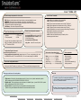
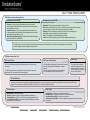
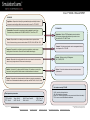
OSI MODEL
Application : Responsible for identifying and establishing the availability of desired
comm partner and verifying sufficient resources exist for comm. Ex: FTP, SMTP
TCP/IP MODEL
Presentation : Responsible for presenting the data in standard formats. Some
Presentation layer standards are JPEG, MPEG, MIDI, PICT, Quick Time, TIFF.
Session : Responsible for co-ordinating communication between systems/nodes.
Some of the session layer protocols and interfaces: NFS, RPC, SQL, ASP, DNA SCP
Application : Defines TCP/IP application protocols and how
host programs interface with transport layer services to use
the network. Ex: FTP, SMTP, Telnet
Transport : Provides communication session management between
host computers. Ex: TCP, UDP
Transport : Responsible for multiplexing upper-layer applications, session mgmt
tearing down of virtual circuits, flow control and to maintain data integrity.
Network : Responsible for sending packets from the source network to the destination
network using routing methods. Routers work at network layer.
Datalink : Consists of LLC sublayer and MAC sublayer. LLC handles error control, flow
flow control, framing etc. MAC handles access to shared media such as ethernet.
Internet : Performs routing of IP datagrams.
Ex: IP, ARP, ICMP
Physical : Controls the hardware devices and media that make
up the network.
Physical : Responsible for ultimate transmission of data over network communications
media. Some of the standard interfaces at physical layer are EIA/TIA-232, V.24,V.35, HSSI
Port numbers used by TCP/UDP
Some important port numbers
FTP : Port 20-21
TFTP : Port 69
Telnet : Port 23
SMTP : Port 25
DHCP : Ports 67 and 68
DNS : Port 53
POP3 : Port 110
HTTP : Port 80
0-255 : Used for public applications
255-1023 : Assigned to companies
Above 1023 : Used by upper layers to set up sessions with other hosts and by
TCP to use as source and destination addresses.
Copyright © 2011 SimulationExams.com
* All trademarks are duly recognised
* Best printed in landscape mode
CCNA Network Simulator
CCNA Exam Simulator
CCENT Exam Simulator
CCNA ICND2 Exam Simulator
CCNP BSCI Exam Simulator
cvcccccCisco
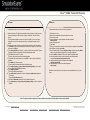
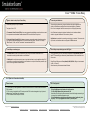
Cisco™ CCNA : IOS
Internal memory components of a cisco router
Router Cursor Commands
ROM : Memory containing micro-code for basic functions to start and maintain the router.
RAM/DRAM : Stores the running configuration, routing tables, and packet buffers.
NVRAM : Memory that does not lose information when power is lost. Stores the system’s
configuration file and the configuration register.
Flash Memory : Stores the compressed IOS image.
<ctrl> A: Move to the beginning of the command line
<ctrl> E: Move to the end of the command line
<ctrl> F: Move forward one character, same as using “Right Arrow”
<ctrl> B: Move backward one character, same as using “Left Arrow".
<ctrl> P: Repeat Previous command, same as using “Up Arrow”
<ctrl> N: Repeat Next (more recent) command, same as using "Down Arrow"
<esc> B: Moves to beginning of previous word.
<esc> F: Moves to beginning of next word.
<ctrl>R: Creates new command prompt, followed by all the
characters typed at the last one.
Router Default Boot Sequence for Cisco IOS
Router boot configuration commands
1. NVRAM
2. Flash (sequential)
boot system ROM : boots from system ROM
boot system flash <IOS file name> : boots
IOS from flash memory
boot system tftp <IOS file name>
<tftp_addr> : boots IOS from a tftp server
3. TFTP server
4. ROM
The router first looks at Startup Config file in NV
RAM, if not available, it falls back to Flash, then
to TFTP and then to ROM.
Configuration Register Command
Router(config)# config-register 0x10x (where that last x is 0-F in hex), when the last x is: 0 = boot
into ROM Monitor mode; 1 = boot the ROM IOS; 2 - 15 = look in startup-config file in NVRAM.
Cisco router configurable locations
Router modes of operation include
Router passwords
Mode---------------------------> Prompt
user exec---------------------> Router>
Privileged----------------------> Router #
global config------------------> Router(config)#
Interface config--------------> Router(config-if)#
Enable password
Console password
Enable Secret
Virtual terminal password (vty)
Auxiliary password
Console port, Virtual Terminals (vty), Auxiliary port, TFTP server and Network management station
Three ways router learns to forward packets
More info
1. Static routes : Configured by the administrator manually. Syntax : ip route <ip-addr><mask-addr><ip-addr>
Ex: R1(config)#ip route 192.168.200.0 255.255.255.0 192.168.1.2
2. Default routes : This is used when a route is not known or is infeasible. Syntax : ip route 0.0.0.0 0.0.0.0 <ip-addr>
Ex: R1(config)#ip route 0.0.0.0 0.0.0.0 192.168.1.2
3. Dynamic routes : In dynamic routing, the routing tables are automatically updated.
Dynamic routing uses broadcasts and multicasts to communicate with other routers.
To enable the Cisco IOS to forward packets destined for
obscure subnets of directly connected networks onto the best
route, use "ip classless" command.
By default, Cisco routers support 5 simultaneous telnet sessions.
This number can be configured using IOS commands.
Copyright © 2011 SimulationExams.com
* All trademarks are duly recognised
* Best printed in landscape mode
CCNA Network Simulator
CCNA Exam Simulator
CCENT Exam Simulator
CCNA ICND2 Exam Simulator
CCNP BSCI Exam Simulator
cvcccccCisco
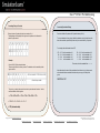
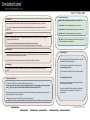
Cisco™ CCNA : Password Recovery
Procedure 1
Procedure 2
Complete these steps in order to recover your password:
Complete these steps in order to recover your password:
1. Attach a terminal or PC with terminal emulation to the console port of the router and
set terminal settings to 9600 baud rate, No parity, 8 data bits, 1 stop bit, No flow
control.
The configuration register is usually set to 0x2102 or 0x102. If you can no longer
access the router you can safely assume that your configuration register is set to
0x2102.
2. Use the power switch in order to turn off the router, and then turn the router back on.
3. Press Break on the terminal keyboard within 60 seconds of power up in order to put
the router into ROMmon.
4. Type confreg 0x2142 at the rommon 1> prompt in order to boot from Flash. This step
bypasses the startup configuration where the passwords are stored.
5. Type reset at the rommon 2> prompt.
The router reboots, but ignores the saved configuration.
6. Type no after each setup question, or press Ctrl-C in order to skip the initial setup
procedure.
7. Type enable at the Router> prompt.
You are in enable mode and should see the Router# prompt.
8. Type configure memory or copy startup-config running-config in order to copy
the nonvolatile RAM (NVRAM) into memory.
9. Type configure terminal.
The router(config)# prompt appears.
10. Type enable secret <password> in order to change the enable secret password.
For example:
router(config)#enable secret cisco
11. Issue the no shutdown command on every interface that you use.
12. Type write memory or copy running-config startup-config in order to commit the
changes.
1. Shut down the router.
2. Remove the compact flash that is at the back of the router.
3. Power on the router.
4. Once the Rommon1> prompt appears, enter this command:
confreg 0x2142
5. Insert the compact flash.
6. Type reset.
7. When you are prompted to enter the initial configuration, type No, and press Enter.
8. At the Router> prompt, type enable.
9. At the Router# prompt, enter the configure memory command, and press Enter in
order to copy the startup configuration to the running configuration.
10. Use the config t command in order to enter global configuration mode.
11. Use this command in order to create a new user name and password:
router(config)#username cisco password cisco
12. Use this command in order to change the boot statement:
config-register 0x2102
13. Use this commnd in order to save the configuration:
write memory
Reload the router, and then use the new user name and password to log in to the
router.
Note : The given procedures are generic in nature, and for exact sequence of steps, please refer to product manual.
Copyright © 2011 SimulationExams.com
* All trademarks are duly recognised
* Best printed in landscape mode
CCNA Network Simulator
CCNA Exam Simulator
CCENT Exam Simulator
CCNA ICND2 Exam Simulator
CCNP BSCI Exam Simulator
cvcccccCisco
Cisco™ CCNA : IPv4 Addressing
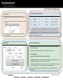
Converting Binary to Decimal
Converting Decimal to Binary
Binary is a base 2 system with only two numbers 0 or 1.
The weightage of binary digits from right most bit position to the left most bit
position is given below.
Decimal is a Base 10 system with 10 possible values (0 to 9)
To convert decimal to binary, simply divide the decimal value by 2 and then write
down the remainder, repeat this process until you cannot divide by 2 anymore.
For example, take the decimal value 157:
Example :
Convert 10011101 into a decimal value.
There are eight bits in the binary number. The decimal value for each bit position is given below:
157 ÷ 2 = 78 with a remainder of 1
39 ÷ 2 = 19 with a remainder of 1
9 ÷ 2 = 4 with a remainder of 1
2 ÷ 2 = 1 with a remainder of 0
78 ÷ 2 = 39 with a remainder of 0
19 ÷ 2 = 9 with a remainder of 1
4 ÷ 2 = 2 with a remainder of 0
1 ÷ 2 = 0 with a remainder of 1 To convert, write this remainder first----------->
Next write down the value of the remainders from bottom to top (in other words
write down the bottom remainder first and work your way up the list) which
gives:
10011101 = 157
To convert, you simply take a value from the top row wherever there is a 1 below,
and then add the values together.
i.e,
1*27 + 0*26 + 0*25 + 1*24 + 1*23 + 1*22 + 0*21 + 1*20
= 128 + 0 + 0 + 16 + 8 + 4 + 0 + 1
= 157 (decimal value)
Copyright © 2011 SimulationExams.com
* All trademarks are duly recognised
* Best printed in landscape mode
CCNA Network Simulator
CCNA Exam Simulator
CCENT Exam Simulator
CCNA ICND2 Exam Simulator
CCNP BSCI Exam Simulator
cvcccccCisco
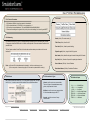
Cisco™ CCNA : IPv4 Addressing
IP Address Intro
IP Address Classes ( Public IP range)
1. An IP address (32 bit number, 4 bytes) consists of four octets seperated
by dots.
Class
Format
A
N.H.H.H
0
0-126
127
B
N.N.H.H
10
128-191
16,384
C
N.N.N.H
110
192 -223
2,097,152
The octet is a binary number of eight digits, which equals the decimal numbers
from 0 to 255.
Leading-bit-pattern
Network-addr-range
Max-netw
Max-hosts
16,777,214
65,534
254
Class D addresses are used for multicasting, they begin with “1110” and the addr range is 224-239.
Class E addresses are reserved addresses that begin with “11110” and the range is 240-254.
2. The internet protocol defines the special network address 127.0.0.1 as a
local loopback address.
IPV4 Header
Private addr range : Class A : 10.0.0.0 to 10.255.255.255, Class B : 172.16.0.0 to 172.31.255.255,
Class C : 192.168.0.0 to 192.168.255.255
Subnet Mask and CIDR notation
A Subnet mask is a 32-bit number that masks an IP address, and divides the IP address into network
address and host address.
Subnet Mask is made by setting network bits to all "1"s and setting host bits to all "0"s.
Default Subnet Masks
Class A : 255.0.0.0, Class B : 255.255.0.0, Class C : 255.255.255.0
CIDR Notation : Classless Inter Domain Routing (CIDR) is a method for assigning IP addresses without
using the standard IP address classes like Class A, Class B or Class C.
In CIDR notation, an IP address is represented as A.B.C.D /n, where "/n" is called the IP prefix or network
prefix. The IP prefix identifies the number of significant bits used to identify a network.
Ex: 216.3.128.12, with subnet mask of 255.255.255.128 may be written as 216.3.128.12/25 using
CIDR Notation.
Copyright © 2011 SimulationExams.com
* All trademarks are duly recognised
* Best printed in landscape mode
CCNA Network Simulator
CCNA Exam Simulator
CCENT Exam Simulator
CCNA ICND2 Exam Simulator
CCNP BSCI Exam Simulator
cvcccccCisco
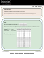
Cisco™ CCNA : Subnetting
Requirement for IPv4 Subnetting
Subnetting Scenarios
1. Efficient use of available IP address space
2. Network traffic isolation
3. Improved security
4. Limiting broadcast messages
The subnetting scenarios may broadly be divided in to two categories:
1. Optimize for a given number of hosts
2. Optimize for a given number of subnets
Finally, determine the host address range for each available subnet.
Subnetting Scenario Question 1
You want X number of subnets, what is the subnet mask ? (Assume we need 10 subnets, i.e, X=10)
Tip : Convert X to binary, determine how many low order bits need to make the number, that many bits is number of high order bits that make up your subnet mask, convert high order bits to
decimal value.
Solution :
Consider the Class C address – N.N.N.H where N is the Network portion and H is the host portion. Host Portion is as shown ----->
Step 1: Convert 10 to binary. Binary equivalent of 10 is as shown --------->
Step 2: Number of low order bits required to make the number is 4 (from the figure shown above)
Step 3: Therefore 4 high-order bits make up the subnet mask, i.e, 128, 64, 32, 16
Add 4 high order bits to create subnet mask i.e. 128+64+32+16=240 (11110000). The subnet mask is 255.255.255.255.240
255.255.255.240 is represented as -------->
Copyright © 2011 SimulationExams.com
* All trademarks are duly recognised
* Best printed in landscape mode
CCNA Network Simulator
CCNA Exam Simulator
CCENT Exam Simulator
CCNA ICND2 Exam Simulator
CCNP BSCI Exam Simulator
cvcccccCisco
Cisco™ CCNA : Subnetting
Subnetting Scenario Question 2
How many subnet bits are required for X number of hosts ? (Assume X value to be 5 in this case)
Tip : Convert X (for the subnets) to binary, determine the number of bits needed for the host portion, additionally determine the subnet mask from the remaining bits, using formula 2ⁿ, find the
relevant number of subnets in this scenario.
.
Solution :
Step 1: Consider the Class C address N.N.N.H, where H is the host portion whose binary and decimal representation is as shown ---->
Convert 5 to binary. Binary equivalent of 5 is as shown --------->
Step 2: As shown in the figure above, the number of bits needed for the host portion are 3. Therefore,
2bits-2=23-2=6 (6>5)
3 bits are required for the host portion for 5 hosts.
Step 3 (Additional): To know the subnet mask , add the decimal value of the remaining 5 bits i.e, (128+64+32+16+8) = 248
Subnet Mask is 255.255.255.248 (11111111.11111111.11111111.11111000)
Number of subnet bits: 29, here 5 bits are used from the host portion of our subnet mask
Therefore number of subnets required is (2n), where 'n' is the number of bits being used from the host portion of our subnet mask i.e. 5
Therefore, 25=32 is the number of subnets
Copyright © 2011 SimulationExams.com
* All trademarks are duly recognised
* Best printed in landscape mode
CCNA Network Simulator
CCNA Exam Simulator
CCENT Exam Simulator
CCNA ICND2 Exam Simulator
CCNP BSCI Exam Simulator
cvcccccCisco
Cisco™ CCNA : Subnetting
Subnetting Scenario Question 3
Determine the range of valid IP Addresses for an X subnet mask ? (Assume X value to be 240 in this case)
Tip : Convert X to binary and determine the decimal value of lowest high order bit, start the range of addresses at that value, and increment the range by that value.
.
Solution :
Step 1: Convert 240 to binary. Binary equivalent of 240 is as shown --------->
Step 2: The decimal value of lowest high order bit is 16 ( 24) as seen from the figure above. Therefore, this number becomes the increment value to determine the IP address ranges.
Subnet Mask: 255.255.255.240
Subnet Bits: 28
Number of Subnets: 16
Host Bits: 4
Hosts per Subnet: 14
The range of addresses for the given mask is as shown ------>
Note: All zeros and all ones host addresses cannot be used.
Copyright © 2011 SimulationExams.com
* All trademarks are duly recognised
* Best printed in landscape mode
CCNA Network Simulator
CCNA Exam Simulator
CCENT Exam Simulator
CCNA ICND2 Exam Simulator
CCNP BSCI Exam Simulator
cvcccccCisco
Cisco™ CCNA : Routing Protocols
Routing Protocols
Types of Routing Protocols
Routed Protocols
Routing protocols job is to maintain routing tables
and route packets appropriately.
Examples of routing are RIP, IGRP, EIGRP, OSPF.
Distance Vector: Distance vector routing determines the direction
and distance to any link in the internetwork. Smaller the metric,
better the path. Distance vector routing is useful for smaller
networks. Ex: RIP and IGRP.
Routed protocols are used to transport user traffic
from source node to destination node.
Examples of routed protocols are IP, IPX and
AppleTalk.
Classful Routing Protocols
Link State: Also known as SPF algorithms, SPF generates the
exact topology of the entire network for route computation by
listening to the first hand information. Bandwidth and delay
are the most widely used metrics. Ex: OSPF and NLSP.
Classful routing protocols do not exchange subnet information during routing information exchanges.
The summarization is always done automatically at major network boundaries.
Ex: RIP v1, IGRP
Balanced Hybrid: Balanced Hybrid combines some aspects of
Link State and Distance Vector routing protocols. It uses
distance vectors with more accurate metrics to determine the
best paths to destination networks. Ex: EIGRP
Classless Routing Protocols
In classless routing protocols, subnet information is exchanged during routing updates.
This results in more efficient utilization of IP addresses. The summarization in classless networks
is manually controlled. Ex: RIP v2, EIGRP, OSPF, BGP v4, and IS-IS
ARP
Default Administrative distances
Directly Connected Interface------> 0
External BGP----------> 20
Static Route------> 1
Internal BGP-----------> 200
Internal EIGRP------> 90
IGRP------> 100
OSPF------> 110
RIP------> 120
IS-IS------> 115
Unknown 255
An administrative distance of 0 represents highest trustworthiness of the route.
An administrative distance of 255 represents the lowest trustworthiness of the route.
Address Resolution Protocol (ARP) is used to resolve a hosts IP
address to its physical address (such as MAC address), to
allow communication on a multi-access medium such as ethernet.
Reverse ARP (RARP) is used to obtain an IP address from physical
address (such as MAC). RARP broadcast may be used to obtain IP
address to boot by diskless workstations over a network.
Copyright © 2011 SimulationExams.com
* All trademarks are duly recognised
* Best printed in landscape mode
CCNA Network Simulator
CCNA Exam Simulator
CCENT Exam Simulator
CCNA ICND2 Exam Simulator
CCNP BSCI Exam Simulator
cvcccccCisco
Cisco™ CCNA : EIGRP and OSPF
EIGRP (Enhanced Interior Gateway Protocol)
Important terms used in EIGRP
Routing metrics used by IGRP
Successor: A route (or routes) selected as the primary route(s) used to
transport packets to reach destination. Note that successor entries are kept in
the routing table of the router.
Feasible successor: A route (or routes) selected as backup route(s) used
to transport packets to reach destination. Note that feasible successor entries
are kept in the topology table of a router.
DUAL (Diffusing Update Algorithm): Enhanced IGRP uses DUAL algorithm to
calculate the best route to a destination
Bandwidth: This is represents the maximum throughput of a link.
MTU (Maximum Transmission Unit): This is the maximum message length that is acceptable to
all links on the path. The larger MTU means faster transmission of packets.
Reliability: This is a measurement of reliability of a network link. It is assigned by the
administrator or can be calculated by using protocol statistics.
Delay: This is affected by the band width and queuing delay.
Load: Load is based among many things, CPU usage, packets processed per sec
For IGRP routing, you need to provide AS (Autonomous System) number in the command. Routers need AS number to exchange routing information.
Routers belonging to same AS exchange routing information.
OSPF(Open Shortest Path First)
OSPF and OSPF Area
OSPF router ID determination
OSPF Priority
OSPF is a link state technology that uses Dijkstra algorithm to compute routing
information.
1. Use the address configured by the ospf router-id command
2. Use the highest numbered IP address of a loopback
interface
3. Use the highest IP address of any physical interface
4. If no interface exists, set the router-ID to 0.0.0.0
The ip ospf priority command is
used to set manually which router
becomes the DR. The range is 0255 and the default is 1. 0 means it
will never be DR or BDR.
An OSPF area is a collection of networks and routers that have the same area
identification.OSPF process identifier is locally significant.
DR and BDR Election
When two or more routers are contending to be a DR (designated Router) on a network segment, the router with the highest OSPF priority will become the DR for that
segment. The same process is repeated for the BDR. In case of a tie, the router with the highest RID will win.
OSPF Area Types
Router Types
Standard Area : Default OSPF area type
Stub Area : External link (type 5) LSAs are replaced with a default route
Totally Stubby Area : Type 3, 4, and 5 LSAs are replaced with a default route
Not So Stubby Area (NSSA) : A stub area containing an ASBR; type 5 LSAs are
converted to type 7 within the area
Internal Router : All interfaces reside within the same area
Backbone Router : A router with an interface in area 0 (the backbone)
Area Border Router (ABR) : Connects two or more areas
AS Boundary Router (ASBR) : Connects to additional routing domains; typically located in
the backbone
Copyright © 2011 SimulationExams.com
* All trademarks are duly recognised
* Best printed in landscape mode
CCNA Network Simulator
CCNA Exam Simulator
CCENT Exam Simulator
CCNA ICND2 Exam Simulator
CCNP BSCI Exam Simulator
cvcccccCisco
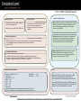
Cisco™ CCNA : Frame Relay
Types of virtual circuits (Vcs) in Frame Relay
Frame relay sub-interfaces
Frame Relay is purely a Layer 2 standard.
Two types of Vcs in FR
When configuring frame-relay using sub interfaces the physical interfaces on
which sub interfaces are configured would not be assigned any IP address.
Even if one is assigned it should be removed prior to configuring frame-relay.
1. Permanent Virtual Circuits (PVCs): these are permanently established connections that are used
for frequent and consistent data transfers between DTEs across a Frame Relay cloud.
If an IP address is assigned to physical interface, the sub interfaces defined
within the physical interface will not receive any frames.
2. Switched Virtual Circuits (SVCs): these are temporary connections used in situations requiring
only occasional data transfers between DTEs across Frame Relay cloud. The terms "Call Setup",
"Data Transfer", "Idle", and "Call Termination" are associated with SVCs.
Split horizon is a method of preventing a routing loop in a network. To overcome the
split horizon, sub-interfaces can be configured on NBMA networks.
Frame Relay connection types
Frame Relay encapsulation types and LMI Types
1. Point-to-Point: In point-to-point connection type, a single sub interface establishes a PVC
connection to another physical interface or sub-interface
Cisco supports two types of Frame Relay encapsulation: cisco (default), and ietf.
Use IETF when setting up a frame-relay network between a Cisco router and a nonCisco router.
2. Multi-point :In multipoint connection type, a single sub-interface is used to establish multiple PVC
connections to several physical interfaces or sub-interfaces. In multipoint Frame-Relay network, split
horizon rule is applicable to broadcast traffic.
Frame-Relay LMI types are Cisco (default), ANSI, Q933A; LMI type is auto-sensed
in IOS v11.2 and up.
Show frame-relay lmi command shows LMI stats.
DLCI (Data Link Connection Identifier)
Salient features
DLCI Configuration
1. DLCIs have only local significance. It means, the end devices over FR network can have different
DLCI numbers
2. DLCI number is provided by the FR service provider. DLCI number is mapped to Layer 3 protocol
address using 'Frame-Relay map' statement.
3. DLCI numbers must be unique on a router.
The command used to assign dlci number to a sub interface is:
R1(config-if)#frame-relay interface-dlci <dlci-number>
Ex: R1(config-if)#frame-relay interface-dlci 100
Note that prior to issuing the above command; issue the following command to get
into proper sub interface configuration mode:
R1(config)#interface serial number.subinterface-number {multipoint | pointto-point} Ex: R1(config)#interface serial 0.1 point-to-point
Copyright © 2011 SimulationExams.com
* All trademarks are duly recognised
* Best printed in landscape mode
CCNA Network Simulator
CCNA Exam Simulator
CCENT Exam Simulator
CCNA ICND2 Exam Simulator
CCNP BSCI Exam Simulator
cvcccccCisco
Cisco™ CCNA : Access-Lists
Wild Card Masking
Access Lists
Wild card masking is used to permit or deny a group of addresses.
For example, if we have a source address 185.54.13.2 and want all the
hosts on the last octet to be considered, we use a wild card mask,
185.54.13.255.
The 32 bit wildcard mask consists of 1’s and 0’s
1 = ignore this bit
0 = check this bit
IP access lists are a sequential list of permit and deny conditions that apply to IP addresses or upper
layer protocols. Access Control Lists are used in routers to identify and control traffic.
Purpose of Access Lists
Types of IP Access Lists
1. Controlling traffic through a router, and
2. Controlling VTY access to a router’s VTY
ports
3. Filter incoming and outgoing packets
4. Restrict contents of routing updates
5. Trigger dial-on-demand routing (DDR) calls
Standard IP Access Lists
Special Case: Host 185.54.13.2 is same as 185.54.13.2 with a wild card
mask of 0.0.0.0, considers only specified IP.
Any is equivalent to saying 0.0.0.0 with a wild card mask of
255.255.255.255. This means none of the bits really matter. All IP
addresses need to be considered for meeting the criteria.
Extended IP Access Lists
Named Access Lists
Standard Access List
Extended Access Lists and Named Access Lists
1. These have the format, access-list [number] [permit or deny] [source_address]
Ex: access-list 1 permit 192.168.2.0 0.0.0.255
2. Place standard access lists as near the destination as possible and extended access lists
as close to the source as possible.
3. Access lists have an implicit deny at the end of them automatically. Because of this, an
access list should have at least one permit statement in it; otherwise the access list will
block all remaining traffic.
4. Access lists applied to interfaces default to outbound if no direction is specified.
Extended Access lists have the format,
access-list {number}{permit or deny} {protocol} {source}source-wildcard [operator
[port]]{destination} destination-wildcard [operator [port]]
With extended IP access lists, we can act on any of the following:
- Source address
- Port information (WWW, DNS, FTP, etc.)
- Destination address
- IP protocol (TCP, ICMP, UDP, etc.)
Ex: access-list 101 permit icmp host 192.168.3.2 any
Named Access lists have the format, ip access-list {standard /extended} name
Ex: ip access-list extended denyping
Permitted numbers for access-lists
1-99: IP standard access list
1000-1099: IPX SAP access list
100-199: IP extended access list
1100-1199: Extended 48-bit MAC address access list
800-899: IPX standard access list
900-999: IPX extended access list
Copyright © 2011 SimulationExams.com
* All trademarks are duly recognised
* Best printed in landscape mode
CCNA Network Simulator
CCNA Exam Simulator
CCENT Exam Simulator
CCNA ICND2 Exam Simulator
CCNP BSCI Exam Simulator
cvcccccCisco
Cisco™ CCNA : NAT
Address Classification
Static NAT
Inside Local : An actual address assigned to an inside host
Maps an unregistered IP address to registered IP (globally unique) addresses on one-to-one basis.
Inside Global : An inside address seen from the outside
The command, ip nat inside source static <local ip> <global ip> configures address translation for
static NAT.
Outside Global : An actual address assigned to an outside host
Dynamic NAT
Outside Local : An outside address seen from the inside
Maps an unregistered IP address to a registered (globally unique) IP address from a group of registered
(globally unique) IP addresses.
NAT Pool : A pool of IP addresses to be used as inside global or
outside local addresses in translations
The command, ip nat inside source list <access-list-number> pool <name>
is used to map the access-list to the IP NAT pool during the configuration of Dynamic NAT.
Overloading
Configuring NAT
A special case of dynamic NAT that maps multiple unregistered IP addresses to a single registered (globally
unique) IP address by using different port numbers.
When configuring NAT, NAT should be enabled on at least
one inside and one outside interface.
Dynamic NAT with overloading is also known also as PAT (Port Address Translation).
Overlapping
1. The command for enabling NAT on inside interface is:
R1(config-if)#ip nat inside
This occurs when your internal IP addresses belong to global IP address range that belong to another
network.
2. The command for enabling NAT on the outside interface
is:
R1(config-if)#ip nat outside
Defining an IP NAT Pool
1. Defining an IP NAT pool for the inside network using the command:
ip nat pool <pool-name> <start-ip> <end-ip> {netmask <net-mask> | prefix-length <prefix-length>} [typerotary] Ex: ip nat pool pool1 200.200.200.3 200.200.200.4 netmask 255.255.255.0
Note that type-rotary is optional command. It indicates that the IP address range in the address pool identifies
hosts among which TCP load is distributed.
Remember to enter into appropriate configuration modes
before entering the commands.
Usually, the inside NAT will be configured on an Ethernet
interface, whereas the outside NAT is configured on a
serial interface.
2. Mapping the access-list to the IP NAT pool by using the command:
ip nat inside source list <access-list-number> pool <pool-name> Ex: ip nat inside source list 1 pool pool1
Copyright © 2011 SimulationExams.com
* All trademarks are duly recognised
* Best printed in landscape mode
CCNA Network Simulator
CCNA Exam Simulator
CCENT Exam Simulator
CCNA ICND2 Exam Simulator
CCNP BSCI Exam Simulator
cvcccccCisco
Cisco™ CCNA : IPv6 Addressing
IPv6 Header
IPv6 : Points to Remember
1. IPv6 address is 128 bits in length represented in hexadecimal
2. IPv6 Loopback address is 0:0:0:0:0:0:0:1, also expressed as ::1.
3. IPv6 reserves two special addresses. They are 0:0:0:0:0:0:0:0 and 0:0:0:0:0:0:0:1.
4. Three transition strategies for migration from ipv6 to ipv4 are dual stacking, 6-to-4 tunneling and NAT-PT
IPv6 Addressing
Version (4 bits) : IP version number (6)
IPv6 address consists of 8 groups of four hexadecimal digits separated by colons and which mainly consists
of 3 segments called Global Prefix which is of 48 bits, subnet part with 16 bits and Interface ID called as Host
part with 64 bits.
Traffic Class (8 bits) : Used for QoS
The first 3 octets constitute Global Prefix, the fourth octet constitute subnet part and the last four form the
Interface ID.
Payload Length (16 bits) : Length of the IPv6 payload
Flow Label (20 bits) : Used for packet labelling
Next Header (8 bits) : Identifies the type of header following the IPv6 header
Hop Limit (8 bits) : Number of hops until the packet gets discarded.
Source Address (128 bits) : Source IP address
Rules : a) One set of 0's in the address can be replaced by :: but this can be done only once
b) One or any number of consecutive groups of 0 value can be replaced with two colons (::)
EUI-64 Format
Destination Address (128 bits) : Destination IP address
IPv6 Communication Types
MAC to EUI-64 conversion inserts hex “FFFE” in the middle of a MAC addr, Then flips
the U/L bit to 1, in order to create a 64-bit interface ID from a 48-bit Mac address.
IPv6 Address Scopes
Unicast : used for one-to-one communication.
There are 3 types of unicast addresses namely
global, unique-local and link-local
Multicast : used for one-to-many communication
IPv6 multicast address begins with "FF"
Anycast : used for one-to-one-of-many
communication
Copyright © 2011 SimulationExams.com
::/0----------------> Default Route
::/128------------> Unspecified
::1/128-----------> Loopback
FC00::/7---------> Unique Local Unicast
FE80::/10--------> Link-Local Unicast
FEC0::/10-------> Site-Local Unicast
FF00::/8----------> Multicast
* All trademarks are duly recognised
* Best printed in landscape mode
CCNA Network Simulator
CCNA Exam Simulator
CCENT Exam Simulator
CCNA ICND2 Exam Simulator
CCNP BSCI Exam Simulator
cvcccccCisco
Cisco™ CCNA : Configuration Commands
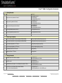
A. Setting Passwords
Sl. No. Task
Commands
R1(config)#line console 0
R1(config-line)#login
R1(config-line)#password ciscocs
R1(config)#line vty 0 4
R1(config-line)#login
R1(config-line)#password ciscovty
R1(config)#line aux 0
R1(config-line)#login
R1(config-line)#password ciscoaux
1
Configure router console password as "ciscocs"
2
Configure router vty password as "ciscovty"
3
Configure router auxiliary password as "ciscoaux"
4
Set the encrypted enable password as "cisco"
R1(config)#enable secret cisco
5
Set the unencrypted enable password as "ccna"
R1(config)#enable password ccna
B. Router Copy Commands
6
Copy the running-configuration to startup-configuration (DRAM to NVRAM)
R1#copy running-config startup-config (copy run start)
7
Copy the startup-configuration to running-configuration (NVRAM to DRAM)
R1#copy startup-config running-config (copy start run)
8
Copy the startup-configuration to a TFTP server
R1#copy startup-config tftp (copy start tftp)
9
Copy the running-configuration to a TFTP server
R1#copy running-config tftp (copy run tftp)
10
Save a backup of the IOS to a TFTP server
R1#copy flash tftp
11
Upgrade the IOS from a TFTP server
R1#copy tftp flash
C. Routing Commands
12
Enable RIP version1 on all 192.168.x.x interfaces
13
Enable RIP version 2
15
Enable EIGRP with an AS number of 1, to all interfaces in the network 19.168.x.x
16
Enable OSPF on any local interface which starts with IP address
10.1.x.x , note the inverted mask and area.
R1(config)#router rip
R1(config-router)#network 192.168.0.0
R1(config)#router rip
R1(config-router)#version 2
R1(config)#router eigrp 1
R1(config-router)#network 192.168.0.0
R1(config)#router ospf 1
R1(config-router)#network 10.1.0.0 0.0.255.255 area 0
Copyright © 2011 SimulationExams.com
CCNA Network Simulator
* All trademarks are duly recognised
* Best printed in landscape mode
CCNA Exam Simulator
CCENT Exam Simulator
CCNA ICND2 Exam Simulator
CCNP BSCI Exam Simulator
cvcccccCisco
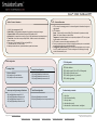
Cisco™ CCNA : VLANs and VTP
VTP – Points to Remember
VLANs – Points to Remember
1. VLAN 1 is the management VLAN.
2. Static VLAN : VLAN is statically assigned to the physical port and never changes.
3. Dynamic VLAN : VMPS automatically assigns VLAN based on MAC
4. Access Link : An access link can carry only one VLAN (used between host and switch port)
5. Trunk Link : A trunk link can carry multiple VLANs. Used to connect to other switches,
routers, or servers
6. Two types of Trunk framing: ISL (Cisco only) and 802.1.q
7. Trunk links can carry 1 to 1005 VLANs
8. Switchport modes are trunk, dynamic desirable, dynamic auto, access.
1. VTP is a Layer 2 messaging protocol. It carries configuration information throughout a
single domain
2. VTP Modes are
Server : Create, modify, or delete VLANs (This is the deafult vtp mode on a switch)
Client : Can't create, change, or delete VLANs
Transparent : Used when a switch is not required to participate in VTP, but only pass
the information to other switches
3. VTP domain is common to all switches participating in VTP
4. Pruning is a technique where in VLANs not having any access ports on an end switch
are removed from the trunk to reduce flooded traffic
5. Configuration revision number is a 32-bit number that indicates the level of revision
for a VTP packet. Each time the VTP device undergoes a VLAN change, the config
revision is incremented by one.
VLAN configuration
VTP Configuration
SW1#vlan database
SW1(vlan)#vtp mode (Server/Client/Transparent)
SW1(vlan)#vtp domain <name>
SW1(vlan)#vtp password <password>
SW1(vlan)#vtp pruning
Creating VLANs
Access Port configuration
SW1#vlan database
SW1(vlan)#vlan 10 name firstvlan
SW1(vlan)#vlan 20 name secondvlan
SW1(config-if)#switchport mode access
SW1(config-if)#switchport access vlan 10
SW1(config-if)#switchport access vlan 20
Access port config to a range of interfaces
Trunk Port configuration
SW1(config)#interface range fa 0/2 - 5
SW1(config-if)#switchport access vlan 10
SW1(config)#interface range fa 0/6 - 10
SW1(config-if)#switchport access vlan 20
SW1(config-if)#switchport mode trunk
SW1(config-if)#switchport trunk encapsulation dot1q
Troubleshooting commands
1. show vlan
2. show vlan-membership
3. show vtp status
4. show interfaces trunk
5. show interface <interface-name> switchport
Copyright © 2011 SimulationExams.com
* All trademarks are duly recognised
* Best printed in landscape mode
CCNA Network Simulator
CCNA Exam Simulator
CCENT Exam Simulator
CCNA ICND2 Exam Simulator
CCNP BSCI Exam Simulator
cvcccccCisco
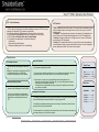
Cisco™ CCNA : Spanning Tree Protocol
STP – Points to Remember
STP Port Roles
1. STP is a layer 2 protocol that runs on switches and bridges, the purpose of STP is to remove
switching loops. By default, STP is enabled on cisco switches.
2. All switches participating in STP exchange info with other switches in the network
Through messages known as BPDUs (Sent out at a frequency of 2 sec on every port)
3. STP port states are Blocked, Listen, Learn, Forward, Disabled
4. The command “show spanning-tree” includes the following info
i. VLAN number
ii. Root bridge priority, MAC address
iii. Bridge timers (Max Age, Hello Time, Forward Delay)
1. Root : A bridge can have only one root port. The root port is the port that leads to the root
bridge. All bridges except the root bridge will have a root port. the root port is in the STP
forwarding state.
2. Designated : One designated port is elected per link (segment). The designated port is
the port closest to the root bridge. Each designated port is in the STP forwarding state
3. Alternate : Alternate ports lead to the root bridge, but are not root ports. The alternate
ports maintain the STP blocking state.
4. Backup: This is a special case when two or more ports of the same bridge (switch) are
connected together, directly or through shared media. In this case, one port is designated,
and the remaining ports block. The role for this port is backup.
Selection Criteria
Root Bridge Selection
Root Port Selection
The switch with the lowest Bridge ID is chosen as
root.
Bridge ID is a combination of switch priority (32768
by default and the range is 0 to 65535 with
increments of 4096) and switch's MAC address
i . If there are 2 or more paths to reach the Root Bridge, select the bridge port associated with
the lowest accumulated path cost. OR
Default Timers
ii. If the path cost to reach the root bridge over 2 or more bridge ports is same, then: select the
neighboring switch with the lowest Switch ID value to reach the Root Bridge OR
Hello-----------------> 2s
Forward Delay-----> 15s
Max Age-------------> 20s
iii. If there are two or more ports on the same bridge with the lowest path cost, then:
* Select the port with the lowest Port Priority value, if you have multiple paths to reach the
Root Bridge via same neighbor switch. OR
* If all the ports are configured with same priority number (32 by default), select the lowest
port number on the switch.
Link Costs
Designated Bridge Selection
i. In a LAN segment, the bridge with the lowest
path cost to the Root Bridge will be the DB OR
ii. If there are two bridges in the LAN segment
with equal path cost to the Root Bridge, then the
Bridge with the lowest Bridge ID becomes the
DB.
Bandwidth
Designated Port Selection
i. The switch port (associated with the DB) on the LAN segment with the lowest accumulated path
cost to the Root Bridge will be selected as DP for the given segment. OR
Cost
10 Mbps-----------> 100
100 Mbps----------> 19
1 Gbps---------------> 4
10 Gbps-------------> 2
ii. If a switch has redundant connections to the network segment, the switch port with the lowest
port priority (32 by default) is selected. OR
iii. If there is again a tie (it can happen if the priorities of the ports on this switch are the same), then
the lowest numbered port on the switch is selected.
Copyright © 2011 SimulationExams.com
* All trademarks are duly recognised
* Best printed in landscape mode
CCNA Network Simulator
CCNA Exam Simulator
CCENT Exam Simulator
CCNA ICND2 Exam Simulator
CCNP BSCI Exam Simulator
cvcccccCisco
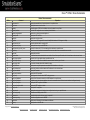
Cisco™ CCNA : Show Commands
Router Show commands
Sl. No.
1.
2.
3.
4.
5.
6.
7.
8.
9.
10.
11.
12.
13.
14.
15.
16.
17.
18.
19.
20.
21.
22.
23.
24.
25.
26.
27.
28.
29.
30.
31.
32.
33.
Command
show access-list
show banner
show cdp
show cdp interface
show cdp neighbor|detail
show cdp traffic
show clock
show flash
show frame-relay lmi
show frame-relay map
show frame-relay pvc <dlci_num>
show history
show hosts
show interfaces
show ip eigrp neighbors
show ip eigrp topology
show ip eigrp traffic
show ip interfaces
show ip interface brief
show ip nat statistics
show ip nat translations
show ip ospf
show ip ospf database
show ip ospf interface
show ip ospf neighbor
show ip ospf neighbor detail
show ip route
show protocols
show running-config
show sessions
show startup-config
show version
show arp
Explanation
Displays all accesslists from all protocols present in a specified router.
Displays the banner set on the router.
Shows the status of CDP such as holdtime value,no.of packets for every 60sec.
It tells the CDP configuration on an interface-by-interface basis.
Displays info on directly connected neighbors.
Displays the CDP traffic info.
Displays the clock (time, date).
Used to view all IOS images and file stored in flash(Default location of IOS images is in flash).
Shows the detailed statistics regarding LMI.
Displays the frame relay inverse ARP table.
Shows all the frame relay PVC's terminated and their statistics at a specified router.
Shows the previously executed commands.IOS device stores the last ten commands that are executed.
Displays the host table.
To view interfaces,status,and statistics for an interface.If u don't lists a specific interface,all of the interfaces on the router are listed.
Shows the list of eigrp neighbors that a specified router has.
Displays the list of successor and feasible successors,as well as other types of routes.
It shows the information about trafiic statistics for eigrp.
Displays status and global parameters associated with the interfaces on the router.
Displays the interface operational status and IP addresses for all router interfaces.
Displays NAT statistics.
Displays the NAT translations.
Displays general information about OSPF routing processes.
Displays lists of information related to the OSPF database for a specific router.
If adjacent router's dont become neighbors, then use the command to check if the local router interface is configured correctly.
Displays the OSPF neighbour information.
Displays all OSPF neighbors in detail.
Displays the IP routing table.
Displays the routing protocols that have been configured and running on a specified router.
Shows the current config stored in RAM.
Shows the telnet sessions that are currently suspended.
Shows the configuration stored in NVRAM.
Display version information for the hardware and firmware.
Displays entries in the ARP table.
Copyright © 2011 SimulationExams.com
* All trademarks are duly recognised
* Best printed in landscape mode
CCNA Network Simulator
CCNA Exam Simulator
CCENT Exam Simulator
CCNA ICND2 Exam Simulator
CCNP BSCI Exam Simulator
cvcccccCisco
Cisco™ CCNA : Show Commands
34.
35.
36.
37.
38.
39.
40.
41.
show ip protocols
show users
show ipv6 interface <interface-name>
show ipv6 rip
show ipv6 ospf
show ipv6 route
show ipv6 protocols
show ip dhcp binding
Displays parameters and current state of the active routing protocol process.
Displays users connected to the router.
Displays ipv6 interface configuration information.
Displays information about all current IPV6 RIP processes.
Displays general information about OSPF routing processes.
Displays routes in the IPV6 routing table.
Displays parameters and current state of the active IPV6 routing protocol processes.
Displays IP addresses assigned to the clients.
Switch Show commands
Sl. No.
Command
Explanation
1.
show banner
Displays the banner.
2.
show flash
Displays the file contents of the flash.
3.
show history
Displays the last 10 commands entered.
4.
show interfaces
To view interfaces,status,and statistics for an interface.
5.
show interfaces vlan 1
Displays the VLAN status and the IP address of VLAN 1.
6.
show ip interface brief
Verifies the IP configuration.
7.
show running-config
Displays the config held in DRAM.
8.
show startup-config
Displays the NVRAM config.
9.
show users
Displays the users currently logged on.
10.
show version
Display IOS version information for the hardware and firmware.
11.
show vlan
Displays vlan information.
12.
show vlan-membership
Displays vlan membership information.
13.
show mac-address-table
Displays mac-address-table information.
14.
show vtp status
Displays vtp status information such as vtp mode, vtp domain etc.
15.
show spanning-tree
Displays spanning-tree statistics,including information about root bridge and port status.
16.
show spanning-tree summary
Displays summary of port states.
17.
show spanning-tree vlan <vlan-id>
Displays STP information for the specified VLAN.
Copyright © 2011 SimulationExams.com
* All trademarks are duly recognised
* Best printed in landscape mode
CCNA Network Simulator
CCNA Exam Simulator
CCENT Exam Simulator
CCNA ICND2 Exam Simulator
CCNP BSCI Exam Simulator