1
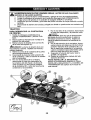
rator's Manual
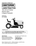
LAWN T ACTO
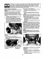
24.0 HP, 54" Mower
EUectric Start
Automatic Transmission
Model No.
917.27686
o EspaSoi,
p. 36
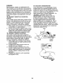
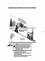
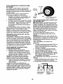
This product has a low emission engine which operates
differently
from previously
built engines. Before you start
engine, read and understand
this Owner's Manual.
IMPORTANT:
Read and follow all Safety
Rules and Instructionsbefore
operatingthis equipment.
For answers to your questions
about this product, Call:
1=800=659=5917
Sears Craftsman Help Line
5 am - 5 pro, Mon - Sat
SEARS, ROEBUCK AND COo, HOFFMAN
ESTATES,
Visit our Craftsman website:www.sears.com/craftsman
IL 60179
U.S.A.
the
Warranty ................................................
2
Safety Rules ..........................................
3
Product Specifications
............................ 6
AssemblyiPre-Ope
ration ....................... 8
Operation .................................................
!2
Maintenance
Schedule ........................
20
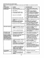
LIMITED
2-YEAR
WARRANTY
ON CRAFTSMAN
Maintenance
.........................................
20
Service and Adjustments ..................... 24
Storage ..................................................
31
Troubleshooting
...................................
32
Sears Service ........................
Back Cover
TRACTOR
AND
BATTERY
ON TRACTOR
When used and maintained according to the operator's manual instructions,
if this tractor
fails due to a defect in material or workmanship
within two years from the date of purchase, call 1°800-4-MY-HOME®
to arrange for free repair.
During the first 30 days of purchase, there wilt be no charge to service the product in
your home° For your convenience,
in-home warranty service will still be available after
the first 30 days of purchase, but a trip charge wil! apply.This
charge will be waived if
you transport the product to an authorized Craftsman drop-off location. For the nearest
authorized location, call 1-800-4-MY-HOME®.
Tractor warranty
coverage
does not include:
• Expendable
items which become worn during normal use, including but not limited to
blades, spark plugs, air cleaners, belts, and oil filters.
° Standard maintenance
servicing, oil changes, or tune-ups.
• Tire replacement
or repair caused by punctures from outside objects, such as nails,
thorns, stumps, or glass.
o Repairs necessary because of operator abuse, including but not limited to damage
caused by towing objects beyond the capability of the tractor, impacting objects that
bend the frame or crankshaft, or over-speeding
the engine.
• Repairs necessary because of operator negligence,
including but not limited to electrical and mechanical
damage caused by improper storage, failure to use the proper
grade and amount of engine oil, failure to keep the deck clear of flammable debris,
or failure to maintain the equipment according to the instructions contained in the
operator's manual.
, Engine (fuel system) cleaning or repairs necessary because of fuel determined to be
contaminated
or oxidized (stale). tn general, fuel should be used within 30 days of its
purchase date°
° Normal deterioration
and wear of the exterior finishes, or product label replacement°
° The tractor battery, which is covered for only 90 days as stated below.
90-DAYS ON BATTERY
For ninety (90) days from the date of purchase, if the battery included with this tractor is
defective in material or workmanship
(our testing proves it will not hold a charge), it will
be replaced free of charge.
During the first 30 days of purchase, there will be no charges to replace the battery in
your home. For your convenience,
in-home warranty service will still be available after
the first 30 days of purchase, but a trip charge will apply. This charge will be waived if
you transport the battery to an authorized Craftsman drop-off location. For the nearest
authorized location, call 1-800-4-MY-HOME®.
All tractor and battery warranty coverage is void if this product is used for commercial
or
rental purposes.
This warranty
applies
only while this product is within the United States.
This warranty gives you specific
vary, from state to state.
Sears, Roebuck
legal rights, and you may also have other rights, which
and Co., Hoffman
Estates,
IL 60179
_DANGER:
This cutting machine is capable of amputating
hands and feet and
throwing objects. Failure to observe the following
safety instructions
could result
in serious injury or death.
_WARNING:
o Never direct discharged
material toward
anyone. Avoid discharging
material
against a wall or obstruction. Material
may ricochet back toward the operator.
Stop the blades when crossing gravel
surfaces.
In order to prevent ac-
cidental starting when setting up, transporting, adjusting or making repairs,
always disconnect spark plug wire and
place wire where it cannot contact spark
plug.
° Do not operate machine without the
entire grass catcher, discharge guard, or
other safety devices in place and working.
° Slow down before turning.
• Never leave a running machine unattended, Always turn off blades, set
parking brake, stop engine, and remove
keys before dismounting.
° Disengage blades when not mowing.
Shut off engine and wait for all parts to
come to a complete stop before cleaning the machine, removing the grass
catcher, or unclogging the discharge
guard°
o Operate machine only in daylight or
good artificial light.
o Do not operate the machine while under
the influence of alcohol or drugs.
° Watch for traffic when operating near or
crossing roadways.
o Use extra care when loading or unloading the machine into a trailer or truck.
o Always wear eye protection when operating machine.
° Data indicates that operators, age 60
years and above, are involved in a large
percentage
of riding mower-related
im
juries. These operators should evaluate
their ability to operate the riding mower
safely enough to protect themselves and
others from serious injury.
° Follow the manufacturer's
recommendation for wheel weights or counterweights.
o Keep machine free of grass, leaves or
other debris build-up which can touch
hot exhaust / engine parts and burn. Do
not allow the mower to plow leaves or
other debris which can cause build-up
to occur. Clean any oil or fuel spillage
before operating or storing the machine.
Allow machine to cool before
_WARNING:
Do not coast down a hilt in
neutral, you may lose control of the tractor.
_IbWARNING:
Tow only the attachments
that are recommended
by and comply with
specifications
of the manufacturer
of your
tractor. Use common sense when towing.
Operate only at the lowest possible speed
when on a slope. Too heavy of a load,
while on a slope, is dangerous.
Tires can
lose traction with the ground and cause
you to lose control of your tractor.
_WARNING:
Engine exhaust, some of
its constituents, and certain vehicle components contain or emit chemicals known
to the State of California to cause cancer
and birth defects or other reproductive
harm.
_IbWARNING:
Battery posts, terminals
and related accessories contain lead and
lead compounds, chemicals known to the
State of California to cause cancer and
birth defects or other reproductive harm.
Wash hands after handling.
!. GENERAL
OPERATION
• Read, understand, and follow all instructions on the machine and in the manual
before starting°
= Do not put hands or feet near rotating
parts or under the machine. Keep clear
of the discharge opening at all times°
° Only allow responsible adults, who are
familiar with the instructions,
to operate
the machine.
° Clear the area of objects such as rocks,
toys, wire, etc. which could be picked
up and thrown by the blades.
• Be sure the area is clear of bystanders before operating.
Stop machine if
anyone enters the area.
o Never carry passengers.
° Do not mow in reverse unless abso=
storage.
lutely necessary.
Always look down and
behind before and while backing.
3
IL SLOPE
OPERATION
• Never carry children, even with the
blades shut off. They may fall off and
be seriously injured or interfere with
safe machine operation. Children who
have been given rides in the past may
suddenly appear in the mowing area for
another ride and be run over or backed
Slopes are a major factor related to loss of
control and tip-over accidents, which can
result in severe injury or death. Operation on all slopes requires extra caution. If
you cannot back up the slope or if you feel
uneasy on it, do not mow it.
o Mow up and down slopes, not across.
o Watch for holes, ruts, bumps, rocks, or
other hidden objects. Uneven terrain
could overturn the machine. Tall grass
can hide obstacles.
• Choose a low ground speed so that you
will not have to stop or shift while on the
slope.
o Do not mow on wet grass° Tires may
lose traction.
Always keep the machine in gear when
going down slopes. Do not shift to neutral and coast downhill.
° Avoid starting, stopping, or turning on a
slope. If the tires lose traction,
disengage the blades and proceed slowly
straight down the slope.
o Keep all movement on the slopes slow
and gradual. Do not make sudden
changes in speed or direction, which
could cause the machine to roll over.
° Use extra care while operating machine
with grass catchers or other attachments; they can affect the stability of the
machine. Do no use on steep slopes.
° Do not try to stabilize the machine by
putting your foot on the ground.
o Do not mow near drop-offs, ditches,
or embankments.
The machine could
suddenly roll over if a wheel is over the
edge or if the edge caves in o
over by the machine.
• Never allow children to operate the
machine.
° Use extra care when approaching
blind
corners, shrubs, trees, or other objects
that may block your view of a child.
W, TOWiNG
o Tow only with a machine that has a
hitch designed for towing. Do not attach
towed equipment except at the hitch
point.
° Follow the manufacturer's
recommendation for weight limits for towed equipment and towing on slopes.
° Never allow children or others in or on
towed equipment.
° On slopes, the weight of the towed
equipment
may cause loss of traction
and loss of control.
° Travel slowly and allow extra distance to
stop.
V. SERVICE
SAFE
HANDLING
OF GASOLINE
To avoid personal injury or property
damage, use extreme care in handling
gasoline. Gasoline is extremely flammable
and the vapors are explosive.
• Extinguish all cigarettes, cigars, pipes,
and other sources of ignition.
° Use only approved gasoline container°
° Never remove gas cap or add fuel with
the engine running. Allow engine to cool
before refueling.
. Never fuel the machine indoors.
• Never store the machine or fuel container where there is an open flame,
spark, or pilot light such as on a water
heater or other appliances.
• Never fill containers inside a vehicle or
III. CHILDREN
Tragic accidents can occur if the operator
is not alert to the presence
of children,
Children are often attracted to the machine
and the mowing activity.
Never assume
that children will remain where you last
saw them°
• Keep children out of the mowing area
and in the watchful care of a responsible
adult other than the operator.
• Be alert and turn machine off if a child
enters the area.
on a truck or trailer bed with plastic liner.
Always place containers on the ground
away from your vehicle when filling.
. Before and while backing, look behind
and down for small children.
4
• Keep machine free of grass, leaves, or
other debris build_up. Clean oil or fuel
spillage and remove any fuel-soaked
debris. Allow machine to cool before
° Remove gas-powered
equipment from
the truck or trailer and refuel it on the
ground. If this is not possible, then
refuel such equipment with a portable
container, rather than from a gasoline
dispenser nozzle.
• Keep the nozzle in contact with the rim
of the fuel tank or container opening at
all times until fueling is complete. Do not
use a nozzle lock-open device.
° If fuel is spilled on clothing, change
clothing immediately.
° Never overfill fuel tank. Replace gas cap
and tighten securely.
GENERAL
SERVICE
storing°
• if you strike a foreign object, stop and
inspect the machine. Repair, if necessary, before restarting.
° Never make any adjustments
or repairs
with the engine running.
° Check grass catcher components
and
the discharge guard frequently and re_
place with manufacturer's
recommended
parts, when necessary.
• Mower blades are sharp_ Wrap the
blade or wear gloves, and use extra caution when servicing them.
° Check brake operation frequently.
Adjust
and service as required°
° Maintain or replace safety and instruction labels, as necessary°
• Never operate machine in a closed area.
• Keep all nuts and bolts tight to be sure
the equipment is in safe working condition.
° Never tamper with safety devices.
Check their proper operation regularly.
° Be alert and turn machine off if a child
enters the area.
° Before and while backing, look behind
and down for small children.
• Mow up and down slopes (15 ° Max), not
across.
o Choose a low ground speed so that you
will not have to stop or shift while on the
slope.
• Avoid starting, stopping, or turning on a
slope, if the tires lose traction,
disengage the blades and proceed slowly
straight down the slope.
• If machine stops while going uphill,
disengage blades, shift into reverse and
back down slowly.
° Do not turn on slopes unless necessary, and then, turn slowly and gradually
downhill, if possible.
o Be sure the area is clear of bystanders before operating.
Stop machine if
anyone enters the area.
o Never carry passengers.
• Do not mow in reverse unless absolutely necessary. Always look down and
behind before and while backing°
° Never carry children, even with the
blades shut off. They may fall off and
be seriously injured or interfere with
safe machine operation. Children who
have been given rides in the past may
suddenly appear in the mowing area for
another ride and be run over or backed
over by the machine.
o Keep children out of the mowing area
and in the watchful care of a responsible
adult other than the operator°
5
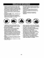
In the state of California the above is re..
quired by law (Section 4442 of the California Public Resources Code). Other states
may have similar laws. Federal laws apply
on federal lands. A spark arrester for the
muffler is available through your nearest
Sears service center (See REPAIR PARTS
manual).
PRODUCT SPECIFICATIONS
Gasoline Capacity
and Type:
4 Gallons
Unleaded Regular
Oi! Type
(API-SG-SL):
SAE 30 (above 32°F)
SAE 5W30
(below 32°F)
Oil Capacity:
W/Filter:
W/O Filter:
64 oz.
60 oz.
Spark Plug:
[Gap: .040")
Champion
Ground
Forward:
Reverse:
0-5.8
0-2.1
Charging System:
16 Amps
@ 3600 RPM
Battery:
Amp/Hr:
Min. CCA:
Case size:
Speed
Blade Bolt Torque:
REPAIR
PROTECTION
AGREEMENTS
QC12YC
Congratulations on making a smart purchase.Your new Craftsmar'_ product is
designed and manufactured for years of
dependable operation_ But like all products,
it may require repair from time to time. That's
when having a Repair Protection Agreement
can save you money and aggravation.
Purchase a Repair Protection Agreement
now and protect yourseff from unexpected
hassle and expense.
Here's what's included in the Agreement:
• Expert service by our 12,000 profesional repair specialists.
• Unlimited service and no charge for
parts and labor on all covered repairs.
• Product replacement
if your covered
product can't be fixed.
o Discount of 10% from regular price of
service and service-related
parts not
covered by the agreement; also, t0% off
regular price of preventive maintenance
check,
35
280
U1R
45-55 Ft. Lbs.
CONGRATULATIONS
on your purchase
of a new tractor. It has been designed,
engineered
and manufactured
to give
you the best possible dependability
and
performance.
Should you experience any problem you
cannot easily remedy, please contact a
Sears or other qualified service center.
We have competent, well-trained representatives and the proper tools to service
or repair this tractor.
Please read and retain this manual. The
instructions wil! enable you to assemble
and maintain your tractor properly. Always
observe the "SAFETY RULES".
o Fast help by phone - phone support
from a Sears representative
on products
requiring in-home repair, plus convenient repair scheduling.
Once you purchase the Agreement, a
simple phone call is all that it takes for you
to schedule service.You can cal! anytime
day or night, or schedule a service appointment online.
Sears has over 12,000 professional
repair
specialists, who have access to over 4.5
million quality parts and accessories°
That's the kind of professionalism
you can
count on to help prolong the life of your
new purchase for years to come. Purchase
your Repair Protection Agreement today!
Some limitations and exclusions apply.
For prices and additional information
call 1-800-827-6655.
CUSTOMER RESPONSIBILITIES
o Read and observe the safety rules.
o Follow a regular schedule in maintaining, caring for and using your tractor,
• Follow the instructions under "Maintenance" and "Storage" sections of this
owner's manual
_!bWARNING,
This tractor is equipped
with an internal combustion
engine and
should not be used on or near any unimproved forest-covered,
brush-covered
or
grass-covered
land unless the engine's
exhaust system is equipped with a spark
arrester meeting applicable local or state
laws (if any). if a spark arrester is used, it
should be maintained in effective working
order by the operator.
SEARS
INSTALLATION
SERVICE
For Sears professional
installation of home
appliances, garage door openers, water
heaters, and other major home items, in
the U,S.A. call 1-800-4-MY-HOME®
6
LL""L '
LL'"
'
..............................
__
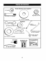
(t) Wheel
,
,
,,
,
Mower Front Wheel
__. =_=i=_hou i de r_Bo_t_
(I) Locknut
(1) 1-1/40oD,
3/8-16
Washer
Mower
(1) Front Link
(5)
Large Retainer
Springs - 7/16
(1) 3/40oD.
Washers
(1) Anti-Swar
(2) Small Retainer
Springs - 5/16
(5) 1-3/!60,D,
__(2)
Washers
Rear Lift Link
Assemblies
Mower Install Slope Sheet
(1) Oil Drain Tube
For Future Use
(2) Keys
Sheet
7
Bar
,,,
Your new tractor has been assembled at the factory with the exception
unassembled
for shipping purposes,
TOOLS
REQUIRED
FOR ASSEMBLY
of those parts left
A socket wrench set will make assembly
easier. Standard wrench sizes you need
are listed be!owr
(I) 3/4" wrench
(1) Pliers
(1) 9/16" wrench
(1) Utility knife
(1) Tire pressure
gauge
When right or left hand is mentioned in
this manual, it means, from your point of
view, when you are in the operating position (seated behind the steering wheel).
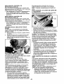
TO REMOVE
TRACTOR
FROM
CARTON
UNPACK
!o
2.
3.
4.
CARTON
NOTE: You may now roll or drive your
tractor off the skid. Follow the appropriate
instruction below to remove the tractor
from the skid,
Remove all accessible loose parts and
parts cartons from carton.
Cut along dashed lines on all four panels of carton. Remove end panels and
lay side panels flat.
Remove mower and packing materials.
Check for any additional loose aprts or
cartons and remove.
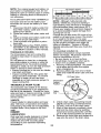
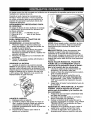
CHECK
WARNING:
Before starting, read, un,.
derstand and follow all instructions in the
Operation section of this manual. Be sure
tractor is in a well-ventilated
area. Be sure
the area in front of tractor is clear of other
people and objects.
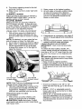
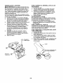
BATTERY
1. Lift hood to raised position.
NOTE: tf this battery is put into service
after month and year indicated on label
(L) (label is located between terminals)
charge battery for minimum of one hour at
6-10 amps, (See "BATTERY" in Maintenance section of this manual for charging
instructions).
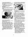
TO ROLLTRACTOR
OFF SKiD
(See
Operation section for location ana
function
of controls)
1. Raise attachment lift lever to its highest
position.
2. Release parking brake by depressing
brake pedal,
3. Place freewheel control in "trans_
mission disengaged
position" (See '_TO
TRANSPORT"
in the Operation section
of this manual).
4. Roll tractor forward off skid_
TO DRIVE
TRACTOR
OFF SKID (See
section
for location
and
function
of controls)
1_ Be sure all the above steps have been
completed.
2o Check engine oil level and fill fuel tank
with gasoline,
3. Place freewheel control in "transmission engaged" position (see "TO
TRANSPORT"
in Operation section of
this manual).
4. Sit on seat in operating position, depress brake pedal and set the parking
brake°
5. Raise attachment lift lever to its highest
position_
Operation
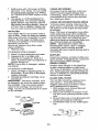
ADJUST
SEAT
1. Sit in seat.
2. Lift up adjustment lever (A) and slide
seat until a comfortable
position is
reached which allows you to press
clutch/brake
pedal all the way down.
3. Release lever to lock seat in position,
8
6, Removekeyfrombag andstart the
engine(see"TOSTARTENGINE"in
the Operationsectionof this manual).
After enginehas started,movethrottle
controlto idle position.
7. Releaseparkingbrake.
8, Slowlydepressforwarddrivepedaland
drivetractoroff skid,
9o Applybraketo stoptractorandset
parkingbrake, to "STOP"position°
10.Turnignitionkey
Continuewith the instructionsthatfollow.
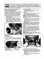
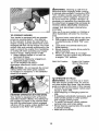
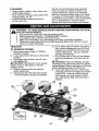
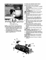
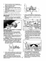
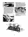
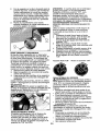
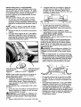
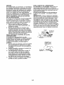
ASSEMBLE
MOWER
NOTE: Be sure mower side suspension
arms (A) are pointing forward before sliding mower under tractor.
4. Slide mower under tractor until it is
centered under tractor.
5o FIRST INSTALL ANTI-SWAY
BAR (S)o
- From right side of mower, insert
ant-sway bar into hole in transmission
bracket (T)o
FRONT WHEEL TO
1. Using shoulder bolt, washer and
Iocknut from parts bag, assemble front
wheel to mower as shown.Tighten
securely_
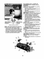
iNSTALL
BELT
MOWER
AND
DRIVE
See MOWER AND DRIVE BELT ASSEMBLY Supplement
Sheet for additional
guidance on this assembly.
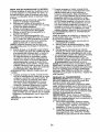
Be sure tractor is on level surface and
engage parking brake.
!. Lower attachment lift lever to it's lowest
position,
_, CAUTION: Lift Sever is spring loaded.
Have a tight grip on lift lever, lower it
slowly and engage in lowest position.
2. Turn steering wheel to the left as far as
it will go and position mower on right
side of tractor with deflector shield to
the righL
- Pivot bar towards you and insert other
end of bar into hole in rear mower
bracket (D)o Move mower as needed to
insert barn
- Secure with washer and retainer
spring as shown,
6_
3_
Remove plastic tie securing belt, bring
belt forward and check belt for proper
routing in all mower pulley grooves.
9
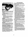
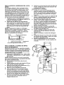
7_
ATTACH MOWER SIDE SUSPENSION
ARMS (A)TO CHASSIS - Position hole
in arm over pin (B) on outside of tractor
chassis and secure with washer and
retainer spring.
Repeat on opposite side of tractor.
12,Insertotherendof link(E)intoholein
frontmowerbracket(H)andsecurewith
washerandretainerspnng(J),
8. ATTACHREARLIFTLINKS(C)- insert
rodendof linkassemblyintoholeintractor liftshaftsuspensionarm (L)andpivot
linkdownto mower.Liftrearcornerof
mowerandpositionslot in tinkassembly
overpinon rearmowerbracket(D)and
securewithwasherandretainerspring.
9o Repeaton oppositesideoftractor.
13.Disengagebelttensionrod(K)fromIockingbracket(L).
14.installbeltontoengineclutchpulley(M),
IMPORTANT:Checkbeltforproperrouting
in allmowerpulleygrooves.
10.Turnsteeringwheelto positionwheels
straightforward.
11,ATTACHFRONTLINK(E)- Workfrom
leftsideof tractor,insertrodendoflink
assemblythroughfrontholeintractor
frontsuspensionbracket(F)andsecure
with retainerspring(G)throughholein
linklocatedbehindthebracket.
15.Engagebelttensionrod(K)on locking
bracket(L),
A CAUTION;Belttensionrodis spring
loaded.Havea tightgripon rodandengage
slowly.
!6. Raiseattachmentliftleverto highest
position.
17.if necessary,adjustgaugewheels
beforeoperatingmoweras shownin the
Operationsectionof thismanual°
02937
10
CHECK
T|RE
PRESSURE
,/'CHECKLIST
Before you operate your new tractor, we
wish to assure that you receive the best
performance and satisfaction from this
Quality Product.
Please review the following checklist:
,/All assembly instructions have been
completed.
#" No remaining loose parts in carton.
,/ Battery is properly prepared and
charged.
,/Seat is adjusted comfortably and tightened securely.
J' All tires are properly inflated. (For shipping purposes, the tires were overinflated at the factory)_
,I Be sure mower deck is properly leveled
side-to-side/front-to-rear for best cutting
results. (Tires must be properly inflated
for leveling).
,/Check mower and drive belts. Be sure
they are routed properly around pulleys
and inside all belt keepers.
,/Check wiring, See that all connections
are still secure and wires are properly
clamped.
v" Before driving tractor, be sure freewheel
control is in "transmission engaged"
position (see 'q'O TRANSPORT" in the
Operation section of this manual).
While learning how to use your tractor,
pay extra attention to the following important items:
,I Engine oil is at proper level.
,/Fuel tank is filled with fresh, clean,
regular unleaded gasoline.
,/"Become familiar with all controls, their
location and function. Operate them
before you start the engine°
¢" Be sure brake system is in safe operating condition_
v" Be sure Operator Presence System
and Reverse Operation System (ROS)
are working properly (See the Operation and Maintenance sections in this
manual),
v' It is important to purge the transmission
before operating your tractor for the first
time. Follow proper starting and transmission purging instructions (See 'TO
START ENGINE" and "PURGE TRANSMISSION" in the Operation section of
this manual).
The tires on your tractor were overinflated
at the factory for shipping purposes° Correct tire pressure is important for best
cutting performance_
o Reduce tire pressure to PSI shown on
tires.
CHECK DECK LEVELNESS
For best cutting results, mower housing should be properly leveled. See "TO
LEVEL MOWER" in the Service and
Adjustments section of this manual.
CHECK FOR PROPER
OF ALL BELTS
POSITION
See the figures that are shown for replacing motion and mower blade drive belts
in the Service and Adjustments section
of this manual. Verify that the belts are
routed correctly.
CHECK BRAKE SYSTEM
After you learn how to operate your tractor, check to see that the brake is operating properly. See "TO CHECK BRAKE"
in the Service and Adjustments section of
this manual.
11
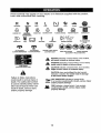
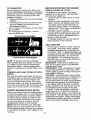
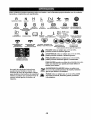
These symbols may appear on your tractor
Learn and understand their meaning.
R
N
H
L
REVERSE
NEUTRAL
HIGH
LOW
or in literature
CHOKE
supplied
FAST
with the product.
SLOW
_ma
ENGINE OFF
REVERSE
OPERATION
SYSTEM (ROS)
ENGINE ON
ENGINE START
PARKING BRAKE
MOWER HEIGHT
IGNmON
SWITCH
MOWER LIFT
÷
;i;
LIGHTS ON
FUEL
ATTACHMENT
CLUTCH DISENGAGED
BATTERY
REVERSE
ATTACHMENT
CLUTCH ENGAGED
FORWARD
DANGER, KEEP HANDS
AND FEET AWAY
CRU,SECOHT.O
CLUTCH/BRAKE
PEDAL
KEEP AREA CLEAR
SLOPE HAZARDS
(SEE SAFETY RULES SECTION)
DANGER indicates a hazard which, if not avoided,
will result tn death or serious injury.
WARNING indicates a hazard which, if not avoided,
could result in death or serious injury.
FREE WHEEL
(Automati€ Models only)
CAUTION indicates a hazard which,if not avoided,
might result In minor or moderate Injury.
CAUTION when usedwithout thealert symbol,
indicatesa situationthat could result in damage
to the tractor and/or engine.
Failure to follow instructions
could result in serious injury or
death. The safety alert symbol
is used to identify safety information about hazards which can
result in death, serious injury
and!or property damage.
HOT SURFACES indicates a hazard which,
tI not avoided,could result tn death, serious injury
and/or property damage.
FIRE indicatesa hazard which, if not avoided,
could result in death, serious injury and/or
property damage.
12
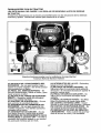
KNOW YOUR TRACTOR
READTHIS
TRACTOR
OWNER'S
MANUAL
AND SAFETY
RULES
BEFORE
OPERATING
Compare the illustrations with your tractor to familiarize yourself with the locations
various controls and adjustments.
Save this manual for future reference.
YOUR
of
03105
Our tractors conform to the applicable safety standards
American National Standards Institute°
of the
(H) LIGHT SWITCH -Turns
the headlights on and off.
(J) CRUISE CONTROL
LEVER - Used to
set forward movement of tractor at desired
(A) ATTACHMENT LIFT LEVER - Used
to raise and lower the mower or other attachments mounted to your tractor.
(B) BRAKE PEDAL - Used for braking
the tractor and starting the engine.
(C) PARKING BRAKE - Locks clutch/
brake pedal into the brake position.
(D) THROTTLE CONTROL - Used to
control engine speed.
(E) ATTACHMENT CLUTCH SWITCH
- Used to engage the mower blades, or
other attachments mounted to your tractor.
(F) IGNITION SWITCH - Used for starting
and stopping the engine.
(G) REVERSE OPERATION SYSTEM
(ROS) "ON" POSITION -Allows operation of mower or other powered attachment while in reverse.
speed without holding the forward drive
pedal.
(K) FORWARD DRIVE PEDALUsed for
forward movement of tractor°
(L) REVERSE
DRIVE PEDAL - Used for
reverse movement of tractor,
(M) FREEWHEEL
CONTROL - Disengages transmission
for pushing or slowly
towing the tractor with the engine off.
(N) CHOKE CONTROL - Used when
starting a cold engine.
(P) SERVICE REMINDER i HOUR METER
- Indicates when service is required for
the engine and mower.
t3
The operation of any tractor can result in foreign objects thrown into the
eyes, which can result in severe eye damage.
Always wear safety glasses
or eye shields while operating your tractor or performing any adjustments
or repairs. We recommend standard safety glasses or a wide vision safety
mask worn over spectacles.
HOW
TO USE YOUR
TO SET PARKING
GROUND
TRACTOR
BRAKE
Your tractor is equipped with an operator
presence sensing
switch+ When engine
is running, any attempt by the operator
to leave the seat without first setting the
parking brake will shut off the engine.
1+ Depress brake pedal (B) al! the way
down and hold.
2. Pull parking brake lever (C) up and
hold, release pressure from brake
pedal (B), then release parking brake
lever, Pedal should remain in brake
position. Make sure parking brake will
hold tractor secure+
DRIVE
-
= To stop ground drive, depress
pedal all the way down.
ENGINE
brake
-
+ Move throttle control (D) between half
and full speed (fast) position.
NOTE: Failure to move throttle control
between half and full speed (fast) posi.+
tion, before stopping, may cause engine to
"backfire".
o Turn ignition key (F) to "STOP" position
and remove key. Always remove key
when leaving tractor to prevent unauthorized use+
,, Never use choke (N) to stop engine.
IMPORTANT:
Leaving the ignition switch
in any position other than "STOP" wilt
cause the battery to discharge and go
dead.
NOTE: Under certain conditions when
tractor is standing idle with the engine
running, hot engine exhaust gases may
cause "browning" of grass. To eliminate
this possibility, always stop engine when
stopping tractor on grass areas.
_J_CAUTION:
Always stop tractor
pletely, as described above, before
the operator's position+
comleaving
STOPPING
MOWER
BLADES
=
° To stop mower blades, push attachment
clutch switch in to disengaged
position
(o),
(I) Attachment
Clutch Switch
Putt Out To "Engage"
(O) Push-In to
"Disengaged"
TO USE'i'HROTTLE
CONTROL
(D)
Always operate engine at full speed (fast).
• Operating engine at less than full speed
(fast) reduces engine's operating efficiency+
° Full speed (fast) offers the best mower
performance.
14
TO ADJUST
TO USE CHOKE CONTROL (N)
Use choke control whenever you are starting a cold engine. Do not use to start a
warm engine.
o To engage choke control, pull knob out.
Slowly push knob in to disengage.
TO MOVE FORWARD
MOWER
CUTTING
The position of the attachment
determines the cutting height.
HEIGHT
lift lever (A)
AND
BACKWARD
The direction and speed of movement is
controlled by the forward and reverse drive
pedals.
1_ Start tractor and release parking brake_
2. Slowly depress forward (K) or reverse
(L) drive pedal to begin movement.
Ground speed increases the further
down the pedal is depressed.
TO USE CRUISE
The cruise control
• Put attachment lift lever in desired cutting height sloL
o Slide pointer tab (T) to desired cutting
height as a reminder for next time you
mow.
The cutting height range is approximately I" to 4". The heights are measured from the ground to the blade tip with
the engine not running. These heights
are approximate and may vary depending
upon soil conditions, height of grass and
types of grass being mowed.
• The average fawn should be cut to approximately 2-1/2 inches during the coot
season and to over 3 inches during hot
months. For healthier and better looking
lawns, mow often and after moderate
growth.
o For best cutting performance,
grass over
6 inches in height should be mowed
twice. Make the first cut relatively high;
the second to desired height.
CONTROL
feature can be used for
forward travel only.
SYSTEM CHARACTERISTICS
The cruise control should only be used
while mowing or transporting
on relatively
smooth, straight surfaces_ Other conditions
such as trimming at slow speeds may
cause the cruise control to disengage. Do
not use the cruise control on slopes, rough
terrian or while trimmimg or turning.
- With forward drive pedal depressed to
desired speed, pull cruise control lever
(J) up and hold while lifting your foot off
the pedal, then release the lever.
To disengage the cruise control, depress
the brake pedal or tap on forward drive
pedal,
TO ADJUST
GAUGE WHEELS
Gauge wheels are properly adjusted
when they are slightly off the ground when
mower is at the desired cutting height in
operating position. Gauge wheels then
keep the deck in proper position to help
prevent scalping in most terrain conditions.
NOTE: Adjust gauge wheels with tractor
on a flat level surface.
1. Adjust mower to desired cutting height
(See "TO ADJUST MOWER CUTTING
HEIGHT" in this section of manual).
2. With mower in desired height of cut
position, gauge wheels should be
assembled so they are slightly off the
ground. Install gauge wheel in appropriate hole. Tighten securely.
3. Repeat for all, installing gauge wheel in
same adjustment hole_
15
_WARNING:
Backing up with the attachment clutch engaged while mowing
is strongly discouraged. Turning the ROS
"ON", to allow reverse operation with the
attachment clutch engaged, should only
be done when the operator decides it is
necessary to reposition the machine with
the attachment engaged. Do not mow in
reverse unless absolutely
necessary.
9/16
USING THE REVERSE
SYSTEM -
TO OPERATE
Only use if you are certain no children or
other bystanders will enter the mowing
area.
1. Depress brake pedal all the way down.
2, With engine running, turn ignition key
counterclockwise
to ROS "ON" position.
3. Look down and behind before and
MOWER
Your tractor is equipped with an operator
presence sensing switch. Any attempt
by the operator to leave the seat with the
engine running and the attachment clutch
engaged will shut off the engine. You must
remain fully and centrally positioned in the
seat to prevent the engine from hesitating
or cutting off when operating your equipment on rough, rolling terrain or hills.
!. Select desired height of cut with attachment lift lever.
2. Start mower blades by engaging attachment clutch control.
TO STOP MOWER BLADES disengage
attachment
OPERATION
4.
while backing.
Slowly depress reverse drive pedal to
start movement.
5. When use of the ROS is no longer
needed, turn the ignition key clockwise
to engine "ON" position.
ROS "ON" Position
Engine "ON" Position
(Normal Operating)
clutch control.
_CAUTION:
Do not operate the mower
without either the entire grass catcher,
on mowers so equipped, or the deflector
shield (S) in place.
TO OPERATE
ON HILLS
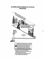
_WARNING:
Do not drive up or down
hills with slopes greater than 15 ° and do
not drive across any slope, Use the slope
guide provided at the back of this manual,
= Choose the slowest speed before starting up or down hills.
° Avoid stopping or changing speed on
hills.
REVERSE OPERATION SYSTEM (ROS)
Your tractor is equipped with a Reverse
Operation System (ROS). Any attempt by
the operator to travel in the reverse direction with the attachment clutch engaged
will shut off the engine unless ignition key
is placed in the ROS "ON" position.
• If stopping is absolutely necessary, push
brake pedal quickly to brake position
and engage parking brake.
° To restart movement, slowly release
parking brake and brake pedal.
• Slowly depress appropriate drive pedal
to slowest setting.
° Make all turns slowly.
!6
TO TRANSPORT
BEFORE
When pushing or towing your tractor, be
sure to disengage transmission by placing
freewheel control in freewheeling
position.
Freewheel control is located at the rear
drawbar of tractor_
1. Raise attachment
lift lever to its highest
position.
2. Pull freewheel control out and into the
slot and release so it is held in the
CHECK
disengaged position.
o Do not push or tow tractor at more than
two (2) MPH.
o To re-engage transmission,
reverse
above procedure.
Transmission Engaged
Transmission Disengaged
NOTE: To protect hood from damage
when transporting your tractor on a truck
or a trailer, be sure hood is closed and
secured to tractor. Use an appropriate
means of tying hood to tractor (rope, cord,
etc.).
TOWING CARTS AND OTHER ATTACHMENTS
Tow only the attachments that are recommended by and comply with specifications
of the manufacturer of your tractor. Use
common sense when towing.Too heavy
of a load, while on a slope, is dangerous.
Tires can lose traction with the ground and
cause you to lose control of your tractor.
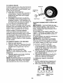
SERVICE REMINDER/HOUR
METER
Service reminder shows the total number
of hours the engine has run and flashes to
indicate that the engine or mower needs
servicing. When service is required, the
service reminder will flash for two hours.
To service engine and mower, see the
Maintenance section of this manual°
NOTE: Service reminder runs when the
ignition key is in any position but "STOP"_
For accurate reading, be sure key remains
in the "STOP" position when engine is not
running.
STARTING
ENGINE
THE
ENGONE
OIL LEVEL
The engine in your tractor has been
shipped, from the factory, already filled
with summer weight oil,
!. Check engine oi! with tractor on level
ground.
2. Remove oil fill cap/dipstick and wipe
clean, reinsert the dipstick and screw
cap tight, wait for a few seconds, remove and read oil level, if necessary,
add oil until "FULU' mark on dipstick is
reached. Do not overfill.
° For cold weather operation you should
change oil for easier starting (See the
oil viscosity chart in the Maintenance
section of this manual)_
= To change engine oil, see the Maintenance section in this manual.
ADD GASOLINE
o Fill fuel tank to bottom of filler neck. Do
not overfill. Use fresh, clean, regular
unleaded gasoline with a minimum of
87 octane. (Use of leaded gasoline will
increase carbon and lead oxide deposits
and reduce valve life). Do not mix oil
with gasoline° Purchase fuel in quantities that can be used within 30 days to
assure fuel freshness.
._CAUTION"
Wipe off any spilled oil or
fuel. Do not store, spill or use gasoline
near an open flame.
IMPORTANT:
When operating in temperatures below32°F(0°C),
use fresh, clean
winter grade gasoline to help insure good
cold weather starting.
CAUTION:
Alcohol blended fuels (called
gasohol or using ethanol or methanol) can
attract moisture which leads to separation and formation of acids during storage.
Acidic gas can damage the fuel system
of an engine while in storage. To avoid
engine problems, the fuel system should
be emptied before storage of 30 days
or longer. Drain the gas tank, start the
engine and let it run until the fuel lines
and carburetor are empty. Use fresh fuel
next season. See Storage Instructions for
additional information. Never use engine
or carburetor cleaner products in the fuel
tank or permanent damage may occur.
17
TO START ENGINE
AUTOMATIC
When starting the engine for the first time
or if the engine has run out of fuel, it wilt
take extra cranking time to move fuel from
the tank to the engine.
1. Be sure freewheel control is in the
transmission engaged position.
2. Sit on seat in operating position,
depress brake pedal and set parking
brake°
3. Move attachment clutch to disengaged
position.
4. Move throttle control to fast position
5. Pull choke control out for a cold engine
start attempt. For a warm engine start
attempt the choke control may not be
needed.
NOTE: Before starting, read the warm
and cold starting procedures
below.
6. Insert key into ignition and turn key
clockwise to start position and release
key as soon as engine starts. Do
not run starter continuously
for more
than fifteen seconds per minute. If the
engine does not start after several
attempts, push choke control in, wait
a few minutes and try again. If engine
still does not start, pull the choke control out and retry°
Before driving the unit in cold weather,
the transmission
should be warmed up as
follows:
i. Be sure the tractor is on level ground.
2. Release the parking brake and let the
brake slowly return to operating position.
3. Allow one minute for transmission
to
WARM
above)
WEATHER
STARTING
WARM
UP
warm up. This can be done during the
engine warm up period.
° The attachments
can be used during
the engine warm-up period after the
transmission
has been warmed up and
may require the choke control be pulled
out slightly_
NOTE: If at a high altitude (above 3000
feet) or in cold temperatures
(below 32 F)
the carburetor fuel mixture may need to
be adjusted for best engine performance
(see "TO ADJUST CARBURETOR"
in the
Service and Adjustments
section of this
manual).
PURGE
TRANSMISSION
_CAUTION:
Never engage or disengage freewheel lever while the engine
is running.
To ensure proper operation and performance, it is recommended
that the
transmission
be purged before operating
tractor for the first time. This procedure wil!
remove any trapped air inside the transmission which may have developed during
shipping of your tractor.
IMPORTANT:
Should your transmission
require removal for service or replacement, it should be purged after reinstallat!on before operating the tractor.
1. Place tractor safely on a level surface
- that is clear of objects and open - with
engine off and parking brake set.
2. Disengage transmission
by placing
freewheel control in disengaged position (See '`TO TRANSPORT"
in this
section of manual).
3. Sitting in the tractor seat, start engine.
After the engine is running, move
throttle control to slow position. Disen_tbgage parking brake.
AUTION: At any time, during step
4, there may be movement of the drive
wheels.
(50 ° F and
7.
When engine starts, slowly push
choke control in until the engine
begins to run smoothly. If the engine
starts to run roughly, pull the choke
control out slightly for a few seconds
and then continue to push the control
in slowly.
= The attachments
and ground drive can
now be used. If the engine does not
accept the load, restart the engine and
allow it to warm up for one minute using
the choke as described above.
COLD WEATHER STARTING (50 ° F and
below)
7. When engine starts, slowly push
choke control in until the engine
begins to run smoothly. Continue to
push the choke control in small steps
allowing the engine to accept small
changes in speed and toad, until the
choke control is fully in. If the engine
starts to run roughly, pull the choke
control out slightly for a few seconds
and then continue to push the control
in slowly. This may require an engine
warm-up period from several seconds
to several minutes, depending on the
temperature.
TRANSMISSION
18
4.
5.
6.
7.
8.
f
Depress forward drive pedal to full
forward position and hold for five (5)
seconds and release pedal, Depress
reverse drive pedal to full reverse position and hold for five (5) seconds and
release pedal° Repeat this procedure
three (3) times.
Shutoff engine and set parking brake.
Engage transmission
by placing freewheel control in engaged position (See
"TO TRANSPORT"
in this section of
manual)°
Sitting in the tractor seat, start engine°
After the engine is running, move
throttle control to half (1/2) speed.
Disengage parking brake.
Drive tractor forward for approximately
five feet then backwards for five feet.
Repeat this driving procedure three
times.
Your transmission
is now purged
ready for normal operation.
I
J
o If grass is extremely tall, it should be
mowed twice to reduce load and pos_
sible fire hazard from dried clippings.
Make first cut relatively high; the second
to the desired height.
o Do not mow grass when it is wet. Wet
grass will plug mower and leave undesirable clumps. Allow grass to dry before
mowing.
° Always operate engine at full throttle
when mowing
to assure better mow_
ing performance
and proper discharge
of material.
Regulate ground speed by
selecting a low enough speed to give the
mower cutting performance as well as
the quality of cut desired,
° When operating attachments,
select a
ground speed that will suit the terrain
and give best performance
of the attachment being used.
and now
MOWING TIPS
= Tire chains cannot be used when the
mower housing is attached to tractor,
o Mower should be properly leveled for
best mowing performance.
See "TO
LEVEL MOWER HOUSING" in the
Service and Adjustments
section of this
manual.
o The left hand side of mower should be
used for trimming.
o Drive so that clippings are discharged
onto the area that has already been
cut° Have the cut area to the right of
the tractor. This will result in a more
even distribution of clippings and more
uniform cutting.
o When mowing large areas, start by
turning to the right so that clippings will
discharge away from shrubs, fences,
driveways, etc. After one or two rounds,
mow in the opposite direction making
left hand turns until finished.
19
MAINTENANCE
SCHEDULE
Check
BEFORE
EVERY
EvE.Y
EACH
8
2_
use
HOURS
_ERY
51)
HOURS
HOURS
EVERY
EVERY
BEFORE
10D
HOURS
SEASON
STORAGE
Brake.Operalion
v"
Check Tire Pressure
e,"
Oheck Ope,rator PresencD & ROe Syslems
-
J
Check for Loose Fasteners
ChecldRep!ace Mower Blades
Lubrication
Chart
ITI
OiCheck
Batten] Level
R IGlean
Battery and Terminals
6_
Check Transaxle Cooling
Check Mower Levelness
Check V-Belts
Check En_qtneOil Level
Ghan_le Engine O!l (with oil filter)
L
_'_,2
.....V",,=
Change EngineOil (without oil fllter
...................
V'
Clean Air Filter
G_
i
N
E
J_
Glean Air Screen
Inspect MuffiertSpark Arrester
;
_1_
Replace Oil Filter (If equipped)
_
'
. '
''
' ,'," '
.................
v,2
Clean Engine Cooling Fins
Replace Spark Plug
"
..........
Replace Alr Filter Paper Cartfldge
Replace Fuel Filter
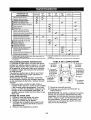
3 -Replace blades more often when mowing in sandy sott
4 - Not required if equipped wi[h maintenance-free battery,
1 * Change more often when operating under a heavy !cad or
Inhigh ambient temperatures,
2 - Service more often when operating tn dirty or dusty conditions.
GENERAL
RECOMMENDATIONS
The warranty on this tractor does not
cover items that have been subjected to
operator abuse or negligence. To receive
full value from the warranty, operator
must maintain tractor as instructed in this
manual.
Some adjustments will need to be made
periodically to properly maintain your
tractor.
At least once a season, check to see if
you should make any of the adjustments
described in the Service and Adjustments
section of this manual.
, At least once a year you should replace
the spark plug, clean or replace air filter,
and check blades and belts for wear.
A new spark plug and clean air filter
assure proper air-fuel mixture and help
your engine run better and last longer.
BEFORE
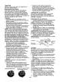
LUBRICATION
_eSpindle "_..__
CHART
_)erSpindle
/-__"-_L.'-._tO
@ Front Wheel_=_'. \ ...;.._--
Front Wheel
Bearing zerk
Bearing zerk (
'_"
Teeth
_'_,_
I_f.ji__
L_ Engine
Z_erk
ManOrel
@General Purpose Grease
@Refer 1o Maintenance
"ENGINE"
Section
IMPORTANT:
Do not oil or grease the
pivot points which have special nylon
bearings_ Viscous lubricants will attract
dust and dirt that will shorten the life of the
self-lubricating
bearings.
If you feel they
must be lubricated, use only a dry, powdered graphite type lubricant sparingly.
EACH USE
1.
2.
3.
4.
Check engine oil level
Check brake operation.
Check tire pressure.
Check operator presence and
ROS systems for proper operation.
5. Check for loose fasteners.
2O
ROS "ON" Position
TRACTOR
Always observe safety rules when performing any maintenance.
BRAKE OPERATION
If tractor requires more than five (5) feet to
stop at highest speed in highest gear on a
level, dry concrete or paved surface, then
brake must be serviced. (See "TO CHECK
BRAKE" in the Service and Adjustments
section of this manual).
TIRES
• When the engine is running with the
ignition switch in the ROS "ON" position
and the attachment clutch engaged,
any attempt by the operator to shift into
reverse should NOT shut off the engine.
BLADE CARE
For best results mower blades must be
o Maintain proper air pressure in all tires
(See PSI on tires)°
o Keep tires free of gasoline, oil, or insect
control chemicals which can harm rubbero
• Avoid stumps, stones, deep ruts, sharp
objects and other hazards that may
cause tire damage.
NOTE; To seal tire punctures and prevent
flat tires due to slow leaks, tire sealant
may be purchased from your local parts
dealer. Tire sealant also prevents tire dry
rot and corrosion.
OPERATOR
PRESENCE
SYSTEM AND
sharp. Replace worn, bent or damaged
blades.
Ak CAUTION:
Use only a replacement
blade approved by the manufacturer
of
your tractor. Using a blade not approved
by the manufacturer of your tractor is
hazardous, could damage your tractor and
void your warranty.
BLADE
gaged position.
PRESENCE
° When the engine is running, any attempt by the operator to leave the seat
without first setting the parking brake
should shut off the engine.
o When the engine is running and the
attachment clutch is engaged, any attempt by the operator to leave the seat
should shut off the engine°
* The attachment clutch should never operate unless the operator is in the seat.
CHECK REVERSE
SYSTEM
OPERATION
REMOVAL
1. Raise mower to highest position to allow access to blades.
NOTE: Protect your hands with gloves
and/or wrap blade with heavy cloth.
2. Remove blade bolt by turning counterclockwise.
3. Install new blade with stamped
"GRASS SIDE" facing the ground.
IMPORTANT:
To ensure proper assembly,
center hole in blade must align with star
on mandrel assembly.
4, install and tighten blade bolt securely
(45-55 Ft. Lbs. torque),
IMPORTANT:
Special blade bolt is heat
treated.
Blade
REVERSE OPERATION
SYSTEM (ROS)
Be sure operator presence and reverse
operation systems are working properly, if
your tractor does not function as described, repair the problem immediately,
o The engine should not start unless the
brake pedal is fully depressed, and the
attachment clutch control is in the disenCHECK OPERATOR
SYSTEM
Engine "ON" Position
(Normal Operating)
Blade Bolt
(Special)
Assembly
Center Hole
BATTERY
(ROS)
Your tractor has a battery charging system
which is sufficient for normal use. How-
• When the engine is running with the
ignition switch in the engine "ON" position and the attachment clutch engaged,
any attempt by the operator to shift into
reverse should shut off the engine.
ever, periodic charging of the battery with
an automotive charger witt extend its life.
° Keep battery and terminals clean_
• Keep battery bolts tight.
° Keep small vent holes open.
° Recharge at 6-10 amperes for 1 hour.
21
NOTE: The original equipment battery on
your tractor is maintenance
free. Do not
attempt to open or remove caps or covers.
Adding or checking level of electrolyte is
not necessary,
TO CLEAN BATTERY
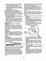
SAE VlSCOSI'W GRADES
TEMPERATURE
AND TERMINALS
Corrosion and dirt on the battery, and
terminals can cause the battery to "leak"
power.
1. Disconnect BLACK battery cable first
then RED battery cable and remove
battery from tractor.
2, Rinse the battery with plain water and
dry.
3. Clean terminals and battery cable ends
with wire brush until bright.
4. Coat terminals with grease or petroleum jelly.
5, Reinstall battery (See "REPLACING
BATTERY" in the SERVICE AND ADJUSTMENTS
section of this manual),
TRANSAXLE COOLING
The transmission fan and cooling fins
should be kept clean to assure proper
cooling.
Do not attempt to clean fan or transmission while engine is running or while the
transmission is hot. To prevent possible
damage to seals, do not use high pressure
water or steam to clean transaxleo
• Inspect cooling fan to be sure fan blades
are intact and clean.
• Inspect cooling fins for dirt, grass clippings and other materials. To prevent
damage to seals, do not use compressed air or high pressure sprayer to
clean cooling fins.
BEFORE NEXT OIL CHANGE
NOTE: Although multi-viscosity oils
(5W30, 10W30 etc.) improve starting in
cold weather, they will result in increased
oil consumption
when used above 32°1=.
Check your engine oil level more frequently to avoid possible engine damage from
running low on oit,
Change the oil after every 50 hours of operation or at least once a year if the tractor
is not used for 50 hours in one year.
Check the crankcase oil level before starting the engine and after each eight (8)
hours of operation.
Tighten oil fill cap/
dipstick securely each time you check the
oil level,
TO CHANGE ENGINE OIL
Determine temperature range expected
before oil change. Al! oil must meet API
service classification
SG-SL.
o Be sure tractor is on level surface,
o Oil will drain more freely when warm°
o Catch oil in a suitable container,
1, Remove oil fill cap/dipstick,
Be careful
not to allow dirt to enter the engine
when changing oil.
2o Remove yellow cap from end of drain
valve and install the drain tube onto the
fitting,
Oil Drain Valve
Closed and
Locked
TRANSAXLE
PUMP FLUID
The transaxle was sealed at the factory
and fluid maintenance is not required for
the life of the transaxle. Should the transaxle ever leak or require servicing, contact
your nearest Sears or other qualified
service center.
Yellow
,,_
,LJ I
_._ ....
I
"
_r= _
, k_%,
,.
_J_-_.' "_. ,.#
F.>'.7"
_
V-BELTS
Check V-belts for deterioration
and wear
after 100 hours of operation and replace
if necessary.The
belts are not adjustable°
Replace belts if they begin to slip from
wear,
ENGINE
3.
_
Drain
Tube
Unlock drain valve by pushing inward
slightly and turning counterclockwise,
4. "Ib open. pull out on the drain valve.
5, After oil has drained completely, close
and lock the drain valve by pushing
inward and turning clockwise until the
pin is in the locked position as shown.
6. Remove the drain tube and replace the
cap onto the end of the drain valve,
LUBRICATION
Only use high quality detergent oil rated
with API service classification
SG-SL
Select the oil's SAE viscosity grade
according to your expected operating
temperature.
RANGE ANTICIPATED
22
7.
Refill engine with oil through oil fill dipstick tube. Pour slowly. Do not overfill.
For approximate capacity see "PRODUCT SPECIFICATIONS"
section of this
manual.
8.
Use gauge on oil fill cap/dipstick
for
checking level. For accurate reading,
tighten dipstick cap securely onto the
tube before removing dipstick. Keep oil
at "FULL' line on dipstick. Tighten cap
onto the tube securely when finished.
CLEAN AIR SCREEN
Air screen must be kept free of dirt and
chaff to prevent engine damage from
overheating. Clean with a wire brush or
compressed air to remove dirt and stubborn dried gum fibers_
CLEAN
Every 100 hours of operation (more often
under extremely dusty, dirty conditions),
remove the blower housing and other cooling shrouds. Clean the cooling fins and
external surfaces as necessary. Make sure
the cooling shrouds are reinstalled.
NOTE:
Operating the engine with a
blocked grass screen, dirty or plugged
cooling fins, and/or cooling shrouds
removed will cause engine damage due to
overheating.
Your engine will not run properly using a
dirty air filter. Clean the foam pre-cleaner
after every 25 hours of operation or every
season. Service paper cartridge every
100 hours of operation or every season,
whichever occurs first.
Service air cleaner more often under
dusty conditions.
1. Remove cover.
2.
3.
4.
PRE-CLEANER
Wash it in liquid detergent and water.
Squeeze it dry in a clean cloth.
Saturate it in engine oil. Wrap it in
clean, absorbent cloth and squeeze to
remove excess oil.
NOTE: If very dirty or damaged,
pre-cleaner.
TO SERVICE
AREAS
To insure proper cooling, make sure the
grass screen, cooling fins, and other external surfaces of the engine are kept clean
at all times.
AIR FILTER
TO SERVICE
AIR INTAKE/COOLING
MUFFLER
Inspect and replace corroded muffler and
spark arrester (if equipped) as it could create a fire hazard and/or damage.
SPARK PLUG(S)
Replace spark plug(s) at the beginning
of each mowing season or after every
100 hours of operation, whichever occurs
first. Spark plug type and gap setting are
shown in "PRODUCT
SPECIFICATIONS"
section of this manual.
replace
CARTRIDGE
1. Clean cartridge by tapping gently on
flat surface. If very dirty or damaged,
replace cartridge.
2. Reinstall precteaner cartridge, cover
and secure.,
IMPORTANT:
Petroleum solvents, such
as kerosene, are not to be used to clean
the cartridge. They may cause deterioration of the cartridge.
Do not oil cartridge. Do not use pressurized air to clean
or dry cartridge.
IN-LINE
FUEL FILTER
The fuel filter should be replaced once
each season. If fue! filter becomes
clogged, obstructing fuel flow to carburetor, replacement
is required.
1. With engine cool, remove filter and
plug fuel line sections.
2. Place new fuel filter in position in fuel
line with arrow pointing towards carburetor,
3. Be sure there are no fuel line leaks and
clamps are properly positioned.
4. Immediately wipe up any spilled gasoline.
Cover
Foam
Clam_mp
Fuel Filter-------__
23
-L_-J
CLEANING
o Clean engine, battery, seat, finish, etc,
of all foreign matter.
• Keep finished surfaces and wheels free
of all gasoline, oil, etc.
• Protect painted surfaces with automotive type wax.
We do not recommend using a garden
hose or pressure washer to clean your
tractor unless the engine and transmission are covered to keep water ouL Water
in engine or transmission
will shorten the
useful life of your tractor. Use compressed
air or a leaf blower to remove grass,
leaves and trash from tractor and mower.
WARNING: TO AVOID SERIOUS INJURY, BEFORE PERFORMING ANY SERVICE OR ADJUSTMENTS:
1. Depress brake pedal fully and set parking brake.
2. Place attachment clutch in "DISENGAGED" position.
3. Turn ignition key to "STOP" and remove key.
4. Make sure the blades and all moving parts have completely stopped_
5. Disconnect spark plug wire from spark plug and place wire where it cannot
come in contact with plug.
TRACTOR
TO REMOVE MOWER
1. Place attachment clutch in "DISENGAGED" position.
2. Lower attachment lift lever to its lowest
position.
3. Disengage belt tension rod (K) from
lock bracket (L).
CAUTION: Belt tension rod is spring
loaded. Have a tight grip on rod and
release slowly.
4. Remove mower belt from electric
clutch pulley (M),
5o Disconnect front link (E) from mower
- remove retainer spring and washer,
6.
Go to either side of mower and disconnect mower suspension arm (A) from
chassis and rear lift link (C) from rear
mower bracket (D) - remove retainer
springs and washers°
7o Go to other side of mower and disconnect the suspension arm and rear lift
link,
CAUTION: After rear lift links are disconnected, the attachment
lift lever will be
spring loaded. Have a tight grip on lift lever
when changing position of the lever.
8. From right side of mower, disconnect
anti-sway bar (S) from right rear mower
bracket (D) _ remove retainer spring
and washer and pul! mower toward
you until the bar fails from the hole in
bracket.
_
02937
24
9. PJrn tractor steering wheel to the left
as far as it will go.
t0oSlide mower out from under right side
of tractor.
TO INSTALL MOWER
24
3.
Follow procedure described in "INSTALL
MOWER AND DRIVE BELT' in the Assembly section of this manual.
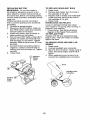
TO LEVEL MOWER
Make sure tires are properly inflated to
the PSI shown on tires° If tires are over
or under inflated, it may affect the appearance of your lawn and lead you to think
the mower is not adjusted properly.
VISUAL
SIDE-TO_SIDE
ADJUSTMENT
A
1. With all tires properly inflated and if
your lawn appears unevenly cut, determine which side of mower is cutting
lower,
NOTE; As desired, you can raise the low
side of mower or lower the high side.
2. Go to side of mower you wish to adjust.
3. With a 3/4" or adjustable wrench, turn
lift link adjustment nut (A) to the left
to lower the mower, or, to the right to
raise the mower.
Turn nut right
to raise mower
Raise mower to its highest position,
At both sides of mower, position blade
at side and measure the distance
(A) from bottom edge of blade to the
ground. The distance should be the
same on both sides.
A
4.
If adjustment
is necessary, see steps 2
and 3 in Visual Adjustment
instructions
above.
5. Recheck measurements,
adjust if necessary until both sides are equal,
FRONT-TO-BACK
ADJUSTMENT
IMPORTANT:
Deck must be level sideto-side,
To obtain the best cutting results, the
mower blades should be adjusted so the
front tip is 1/8" to 1/2" lower than the rear
tip when the mower is in its highest position.
CAUTION:
Blades are sharp_ Protect
your hands with gloves and/or wrap blade
with heavy cloth.
= Raise mower to highest position.
° Position any blade so the tip is pointing
straight forward. Measure distance (B)
to the ground at front and rear tip of the
blade.
Turn nut left
to lower mower
NOTE: Each full turn of adjustment nut will
change mower height about 3/16".
4_ Test your adjustment by mowing some
uncut grass and visually checking the
appearance°
Readjust, if necessary,
until you are satisfied with the results.
,
If front tip of blade is not !/8" to I/2"
lower than the rear tip, go to the front of
tractor.
• With an 11/16" or adjustable wrench,
loosen jam nut A several turns to clear
adjustment nut B.
° With a 3/4" or adjustable wrench, turn
front link adjustment nut (B) clockwise
(ltighten) to raise the front of mower, or,
counterclockwise
(loosen) to lower the
front mower.
PRECISION
SIDE-TO-SIDE
ADJUSTMENT
!.
With all tires properly inflated, park
tractor on level ground or driveway°
_1_CAUTION:
Blades are sharp. Protect
your hands with gloves and/or wrap blade
with heavy cloth.
25
TO REPLACE
MOWER
MOWER
DRIVE
DRIVE
BELT
BELT REMOVAL
1. Park tractor on a level surface° Engage
parking brake,
2. Lower attachment lift lever to its lowest
position.
3. Disengage belt tension rod (K) from
ock bracket (L),
CAUTION: Belt tension rod is spring
loaded. Have a firm grip on rod and release slowly.
4. Remove screws (P) from R,H_ and L,H.
mandrel covers and remove covers
(a)
5.
Tighten adjust nut
B to raise mower
Loosen adjust nut
B to lower mower
Remove any dirt or grass clippings
which may have accumulated
around
mandrels and entire upper deck surface.
6. Remove belt from electric clutch pulley
(M), both mandrel pulleys (R) and all
idler pulleys (S)o
MOWER
Loosen jam nut A first
DRIVE
BELT INSTALLATION
1.
Install belt around both mandrel pulleys (R) and around idler pulleys (S) as
shown.
2. Install belt onto electric clutch pulley
(M).
IMPORTANT:
Check belt for proper routing in all mower pulley grooves,
3o Reassemble
R.H. and L.H. mandrel
NOTE: Each full turn of the adjustment
nut will change mower height about t/8".
o Recheck measurements,
adjust if necessary until front tip of blade is 1/8" to
1/2" lower than the rear tip,
• Hold adjustment
nut in position with
wrench and tighten jam nut securely
against adjustment
nut.
covers (Q). Securely tighten all screws.
Engage belt tension rod (K) on locking
bracket (L).
_}_ CAUTION: Belt tension rod is spring
loaded. Have a tight grip on rod and engage slowly_
5. Raise attachment
lift lever to highest
position,
4.
26
TO ADJUST
ATTACHMENT
CLUTCH
BELT INSTALLATION
1. Install new belt from tractor
The electric clutch should provide years
of service. The clutch has a built-in brake
that stops the pulley within 5 seconds.
Eventually, the internal brake will wear
which may cause the mower blades to
not engage, or, to not stop as required.
Adjustments should be made by a Sears
or other qualified service center.
I, Make sure attachment clutch and ignition switches are in "OFF" position.
2. Adjust the three nylon locknuts until
space between clutch plate and rotor
measures .012" at all three slot locations cut in the side of brake plate.
NOTE: After installing a new electric
clutch, run tractor at full throttle and
engage and disengage electric clutch 10
cycles to wear in clutch plate_
Rotor
2.
3.
4.
5.
6.
7.
8.
9.
Clutch Plate
,012"
Locknut
,_
_-_.
Plate
TO REPLACE MOTION DRIVE BELT
Park the tractor on level surface. Engage
parking brake, For ease of service there is
a belt installation guide decal on bottom of
left footrest.
BELT REMOVAL
-
1_ Remove mower (See "TO REMOVE
MOWER" in this section of manual).
NOTE: Observe entire motion drive belt
and position of all belt guides and keepers°
2o Disconnect clutch wire harness (A).
3. Remove anti-rotation link (B) on right
side of tractor.
4.
Remove belt from stationary idler (C)
and clutching idler (D).
5. Remove belt from centerspan idler (E).
6. Pull belt slack toward rear of tractor.
Carefully remove belt upwards from
transmission
input pulley and over
cooling fan blades (F)o
7. Remove belt downward from engine
pulley and around electric clutch (G).
8_ Slide belt toward rear of tractor, off the
steering plate (H) and remove from
tractor,
27
rear to
front, over the steering plate (H) and
above clutch brake pedal shaft (J).
Pull belt toward front of tractor and roll
belt around electric clutch and onto
engine pulley (G)_
Pull belt toward rear of tractor_ Care_
fully work belt down around transmission cooling fan and onto the input
pulley (F). Be sure belt is inside the
belt keeper.
Install belt on centerspan idler (E).
Install belt through stationary idler (C)
and clutching idler (D).
Reinstall anti-rotation
link (B) on right
side of tractor. Tighten securely.
Reconnect clutch harness (A).
Make sure belt is in all pulley grooves
and inside all belt guides and keepers.
Install mower (See 'q'O INSTALL
MOWER" in this section of manual).
TO CHECK
BRAKE
If tractor requires more than five (5) feet to
stop at highest speed in highest gear on a
level, dry concrete or paved surface, then
brake must be serviced.
You may also check brake by:
1. Park tractor on a level, dry concrete or
paved surface, depress clutch/brake
pedal all the way down and engage
parking brake°
2. Disengage transmission by placing
freewheel control in "transmission
disengaged" position° Pull freewheel control out and into the slot and release so
it is held in the disengaged position.
The rear wheels must lock and skid
when you try to manually push the tractor
forward. If the rear wheels rotate, then the
brake needs to be serviced. Contact a
Sears or other qualified
FRONT WHEEL
service
TOE-IN/CAM
center.
BER
Your new tractor front wheel toe-in and
camber is set at the factory and is normal.
The front wheel toe-in and camber are
not adjustable.
If damage has occurred to
affect the factory set front wheel toe-in or
camber, contact a Sears or other qualified
service center.
TO REMOVE
1.
2.
WHEEL
FOR REPAIRS
Block up axle securely°
Remove axle cover, retaining ring and
washers to allow wheel removal (rear
wheels have a square key - Do not
lose).
3. Repair tire and reassemble.
NOTE; On rear wheels only: align
grooves in rear wheel hub and axle. Insert
square key.
4. Replace washers and snap retaining
ring securely in axle groove.
5. Replace axle cover.
NOTE: To seal tire punctures and prevent
flat tires due to slow leaks, purchase and
use tire sealant from Sears. Tire sealant
also prevents tire dry rot and corrosion.
Washers
Retaining
Ring
t
Axle Cover
_X.Square
Key (Rear
Wheel Only)
TO START ENGINE WITH A WEAK BATTERY
_,WARNING:
Lead-acid batteries generate explosive gases. Keep sparks, flame
and smoking materials away from batteries. Always wear eye protection when
around batteries.
if your battery is too weak to start the
engine, it should be recharged. (See "BATTERY" in the MAINTENANCE section of
this manual).
If "jumper cables" are used for emergency
starting, follow this procedure:
IMPORTANT: Your tractor is equipped
with a 12 volt system. The other vehicle
must also be a 12 volt system. Do not use
your tractor battery to start other vehicles.
TO ATTACH JUMPER
CABLES
-
1. Connect one end of the RED cable
to the POSITIVE (+) terminal of each
battery(A-B),
taking care not to short
against tractor chassis.
2. Connect one end of the BLACK cable
to the NEGATIVE (-) terminal (C) of
fully charged battery.
3. Connect the other end of the BLACK
cable (D) to good chassis ground,
away from fuel tank and battery.
TO REMOVE CABLES, REVERSE
ORDER t. BLACK cable first from chassis and
then from the fully charged battery.
2. RED cable last from both batteries.
Weak or Dead
Battery
28
Fully Charged
Battery
REPLACING
BATTERY
TO REPLACE
!.
2.
_WARNING:
Do not short battery
terminals by allowing a wrench or any
other object to contact both terminals at
the same time. Before connecting battery,
remove metal bracelets, wristwatch bands,
rings, etc.
Positive terminal must be connected
BULB
the backside of the grill.
Replace bulb in holder and install bulb
holder securely back into the hole in
the backside of the grill.
4. Close hood.
INTERLOCKS
AND RELAYS
3.
first to prevent sparking from accidental
grounding.
1. Lift hood to raised position.
2. Disconnect BLACK battery cable (A)
then RED battery cable and carefully
remove battery from tractor_
3. Install new battery with terminals in
same position as old battery.
4. First connect RED battery cable (B) to
positive (+) battery terminal with hex
bolt and keps nut as shown. Tighten
securely. Slide terminal cover (C) over
terminal.
5. Connect BLACK grounding cable to
negative (-) battery terminal with remaining hex bolt and keps nut. Tighten
securely
6_ Close hood.
_
HEADLIGHT
Raise hood.
Remove bulb holder from the hole in
Loose or damaged wiring may
your tractor to run poorly, stop
prevent it from starting_
• Check wiring. See electrical
diagram in the Repair Parts
TO REPLACE FUSE
cause
running, or
wiring
section,
Replace with 30 amp automotive-type
plug-in fuse. The fuse holder is located
behind the dash_
TO REMOVE HOOD AND GRILL ASSEMBLY
1, Raise hood°
2o Unsnap headlight wire connector.
3. Stand in front of tractor, Grasp hood at
sides, tilt toward engine and lift off of
tractor,
4. When replacing hood, be sure to reconnect the headlight wire connector.
egative
(Black)
Cable
Hood
Headlight Wire
Connector
Positive
(Red)
Cable
29
ENGINE
TO ADJUST
Maintenance, repair, or replacement of
the emission control devices and systems,
which are being done at the customers expense, may be performed by any non-road
engine repair establishment
or individual.
Warranty repairs must be performed by an
authorized engine manufacturer's
service
outlet,
TO ADJUST THROTTLE CONTROL
CABLE
Your carburetor is not adjustable. If your
engine does not operate properly due to
suspected carburetor problems, take your
tractor to a Sears or other qualified service
center for repair and/or adjustment.
High speed stop is factory adjusted° Do
not adjust - damage may result.
IMPORTANT:
Never tamper with the
engine governor, which is factory set
for proper engine speed. Overspeeding the engine above the factory high
speed setting can be dangerous,
tf you
think the engine-governed
high speed
needs adjusting, contact a Sears or other
qualified service center,, which has proper
equipment and experience to make any
necessary adjustments_
The throttle control has been preset at the
factory and adjustment should not be necessary. Check adjustment
as described
below before loosening cable° if adjustment is necessary, proceed as follows:
i. With engine not running, move throttle
control lever to fast position.
2. Check that swivel is against stop. If it is
not, loosen cable clamp screw and pull
cable back until swivel is against stop.
Tighten cable clamp screw securely°
TO ADJUST CHOKE CONTROL
The choke control has been preset at
the factory and adjustment should not be
necessary. Check adjustment as described
below before loosening cable° If adjustment is necessary, proceed as follows:
1. With engine not running, move choke
control (located on dash panel) to full
choke position_
2. Loosen knob and remove cover assembly from air cleaner,
3. Choke should be closed. If it is not,
loosen casing clamp screw and move
choke cable until choke is completely
closed. Tighten casing clamp screw
securely.
4. Replace air cleaner cover assembly
and tighten knob.
Swivel
CARBURETOR
Clamp
Screw
m
3O
acids during storage. Acidic gas can damage the fuel system of an engine while in
storage_
• Empty the fuel tank by starting the engine and letting it run until the fuel lines
and carburetor are empty.
o Never use engine or carburetor cleaner
products in the fuel tank or permanent
damage may occur,
o Use fresh fuel next season,
Immediately
prepare your tractor for storage at the end of the season or if the tracWill not be used for 30 days or more.
RNING:
Never store the tractor
with gasoline in the tank inside a building
where fumes may reach an open flame
or spark° Allow the engine to cool before
storing in any enclosure,
TRACTOR
When tractor is to be stored for a period
of time, clean it thoroughly, remove all dirt,
grease, leaves, etc. Store in a clean, dry
area°
1, Clean entire tractor (See "CLEANING"
in the Maintenance
section of this
manual).
2, Inspect and replace belts, if necessary
(See belt replacement
instructions in
the Service and Adjustments
section of
this manual).
3, Lubricate as shown in the Maintenance
section of this manual.
4. Be sure that all nuts, bolts and screws
are securely fastened,
Inspect moving
parts for damage, breakage and wear°
Replace if necessary.
5. Touch up all rusted or chipped paint
surfaces; sand lightly before painting.
NOTE; Fuel stabilizer is an acceptable
alternative in minimizing the formation of
fuel gum deposits during storage, Add
stabilizer to gasoline in fuel tank or storage container.
Always follow the mix ratio
found on stabilizer container,
Run engine
at least 10 minutes after adding stabilizer
to allow the stabilizer to reach the carburetor. Do not empty the gas tank and carburetor if using fuel stabilizer.
ENGINE OIL
Drain oil (with engine warm) and replace
with clean engine oil, (See "ENGINE" in
the Maintenance section of this manual),
CYLINDER(S)
1. Remove spark plug(s),
2, Pour one ounce of oil through spark
plug hole(s) into cylinder(s),
3. Turn ignition key to start position for a
few seconds to distribute oil,
BATTERY
o Fully charge the battery for storage.
a After a period of time in storage, battery
may require recharging,
o To help prevent corrosion and power
leakage during long periods of storage,
battery cables should be disconnected
and battery cleaned thoroughly (see "TO
CLEAN BATTER"( AND TERMINALS"
in
the Maintenance
section of this manual),
o After cleaning, leave cables disconnected and place cables where they
cannot come in contact with battery
terminals.
4,
Replace
with new spark plug(s),
° If battery is removed from tractor for
storage, do not store battery directly on
concrete or damp surfaces,
ture, Do not use plastic. Plastic cannot
breathe which allows condensation
to
form and will cause your tractor to rust,
IMPORTANT:
Never cover tractor while
engine and exhaust areas are still warm.
OTHER
• Do not store gasoline
to another.
from one season
= Replace your gasoline can if your can
starts to rust. Rust and/or dirt in your
gasoline will cause problems,
° if possible, store your tractor indoors
and cover it to give protection from dust
and dirt.
° Cover your tractor with a suitable protective cover that does not retain mois-
ENGINE
FUEL SYSTEM
IMPORTANT: it is important to prevent
gum deposits from forming in essential
fuel system parts such as carburetor, fuel
hose, or tank during storage. Also, alcohol
blended fuels (called gasohol or using
ethanol or methanol) can attract moisture
which leads to separation and formation of
31
TROUBLESHOOTING
CHART:
See appropriatesectionin
PROBLEM
CAUSE
Will not start
manualunless
directedto
Sears servicecenter
.................................. CORRECTION
1. Out of fuel.
2o Engine not"CHOKED"
properly.
3. Engine flooded.
4o
5.
16.
17.
i8.
Bad spark plug.
Weak or dead battery.
Dirty air filter.
Dirty fuel filter.
Water in fuel
i9. Loose or damaged wiring.
10. Carburetor out of adjustment.
11. Engine valves out of
adjustment.
Hard to start
1.
2.
3.
4.
5.
Dirty air filter.
Bad spark plug.
Weak or dead battery.
Dirty fuel filter°
Stale or dirty fuel.
6. Loose or damaged wiring.
7_ Carburetor out of adjustment.
8_ Engine valves
adjustment.
out of
1o Fill fuel tank.
2. See 'qO START ENGINE" in
Operation section.
3, Wait several minutes before
attempting to start.
4. Replace spark plug.
5. Recharge or replace battery.
6. Clean/replace
air filter.
7. Replace fue! filter.
8. Empty fuel tank and carburetor, refill tank with fresh gasoline and replace fuel filter.
9. Check all wiring.
I0o See "To Adjust Carburetor"
in Service and Adjustments
section.
t 1.Contact a Sears or other
qualified service center.
1. Clean/replace
air filter.
2. Replace spark plug.
3. Recharge or replace battery.
4. Replace fuel filter.
5. Empty fuel tank and refill tank
with fresh, clean gasoline.
6. Check all wiring.
7o See "To Adjust Carburetor"
in
Service and Adjustments
section.
8. Contact a Sears or other
qualified service center.
,,, ,,, ,,,,,, ,,,,,,, ,,,,,
Engine will not
turn over
, ,,,,,
,,
,,
9. Faulty operator presence
switch(es).
Depress brake pedal.
Disengage attachment clutch.
Recharge or replace battery.
Replace fuse.
Clean battery terminals.
Check all wiring.
Check/replace ignition switch.
Check/replace
solenoid or
starter.
9. Contact a Sears or other
qualified service center.
Engine clicks but
will not start
1. Weak or dead battery.
2. Corroded battery terminals.
3. Loose or damaged wiring°
4. Faulty solenoid or starter.
1.
2.
3.
4.
Recharge or replace battery.
Clean battery terminals.
Check all wiring°
Check/replace
solenoid or
starter.
Loss of power
1.
1.
Raise cutting height!reduce
speed.
Adjust throttle control.
Clean underside of mower
housing.
Clean/replace
air filter.
Check oil level/change
oil.
1.
12.
j3.
4.
5.
6.
7.
8_
Brake pedal not depressed.
Attachment clutch is engaged.
Weak or dead battery.
Blown fuse.
Corroded battery terminals.
Loose or damaged wiring.
Faulty ignition switch.
Faulty solenoid or starter_
Cutting
fast.
too much grass/too
21 Throttle in "CHOKE" position.
Build-up of grass, leaves and
trash under mower.
4. Dirty air filter°
5. Low oil level/dirty oil.
32
!.
2.
3.
4.
5.
6.
7.
8.
2.
3o
4.
5.
TROUBLESHOOTING CHART:
See appropriate section in manual unless directed to Sears service center
PROBLEM
CAUSE
Loss of power
(continued)
6,
CORRECTION
Faulty spark plugo
7r Dirty fuel filter,
8. Stale or dirty fuelo
9, Water in fuel
10,Spark
11,
12.
13,
14.
plug wire loose.
Dirty engine air screen/fins.
Dirty/clogged
muffler,
Loose or damaged wiring,
Carburetor out of adjustment.
t 5. Engine valves out of
adjustment,
6o Clean and regap or change
spark plug,
7. Replace fuel filter.
8. Empty fuel tank and refill tank
with fresh, clean gasoline.
9, Empty fuel tank and carburetor, refill tank with fresh gasoline and replace fuel filter.
10, Connect and tighten spark
plug wire.
11. Clean engine air screen/fins.
12. Clean/replace
muffler.
13.Check all wiring.
14o See "To Adjust Carburetor"
in Service and Adjustments
section,
1&Contact
a Sears or other
qualified
service
center.
....
Excessive
vibration
1. Worn, bent or loose blade,
2.
Bent blade mandrel°
3, Loose/damaged
Engine dies when
tractor is shifted
into reverse
.
part(s),
Reverse operation system
(ROS) is not "ON" while
mower or other attachment
is engaged,
Engine continues
to run when
operator leaves
seat with
attachment
clutch engaged
1, Faulty operator-safety
presence control system,
Poor cut - uneven
1_ Worn, bent or loose blade.
1. Replace blade. Tighten blade
bolt.
2o Contact a Sears or other
3,
qualified service center.
Tighten loose part(s)_
Replace damaged parts,
1. Turn ignition key to
ROS "ON" position,
See Operation section,
1o Check wiring, switches and
connections,
if not corrected,
contact a Sears or other
qualified
2,
Mower deck not level.
3.
Buildup of grass, leaves, and
trash under mower,
4. Bent blade mandrel.
.
Clogged mower deck vent
from build-up of grass, leaves,
and trash around mandrels,
33
,J ,J,,,,,,L,, ,,
service
center.
I.
Replace blade, Tighten blade
bolt.
2, Level mower deck.
3, Clean underside of mower
housing,
Contact a Sears or other
qualified service center.
5, Clean around mandrels to
open vent holes,
4.
TROUBLESHOOTING CHART:
See appropriate section in rnanual unless directed to Sears service center
PROBLEM
Mower blades will
not rotate
CAUSE
1. Obstruction
in clutch
mechanism.
2. Worn/damaged
mower drive
belt.
3. Frozen idler pulley,
4, Frozen blade mandrel.
5,
Poor grass
discharge
CORRECTION
Mower belt off engine pulley,
!.
Remove
obstruction_
2.
Replace
mower drive belt.
3o Replace idler pulley.
4.. Contact a Sears or other
qualified service center.
3. Install belt on engine pulley.
1. Engine speed too slow.
1.
2o Trave! speed too fast.
3. Wet grass.
2.
3.
4.
5.
4.
5.
Mower not level.
Low/uneven tire air pressure.
6. Worn, bent or loose blade.
6.
7.
7.
Buildup of grass, leaves and
trash under mower°
8. Mower drive belt worn.
9. Blades improperly installed_
10. Improper blades used.
1 !. Clogged mower vent
holes from buildup of grass,
leaves, and trash around
mandrels.
housing.
Replace mower drive belt.
Reinstall blades sharp edge
down.
10. Replace with blades listed
in this manual.
11. Clean around mandrels to
8.
9.
open vent holes.
1. Turn light switch "ON".
2. Replace bulb(s) or tamp(s).
3. Check/replace
light switch.
4. Check wiring and connections.
5. Replace fuse.
Headlight(s) not
working
(if so equipped)
1.
2.
3.
4.
5.
Battery will not
charge
1. Bad battery cell(s).
2. Poor cable connections.
3. Faulty regulator
(if so equipped).
4. Faulty alternator.
1. Replace battery.
2. Check/clean
all connections.
t.
1.
.oss
of drive
Light switch is "OFF".
Bulb(s) or lamp(s) burned out.
Faulty light switch_
Loose or damaged wiring.
Blown fuse.
Place throttle control in
"FAST' position_
Shift to slower speed.
Allow grass to dry before
mowing.
Level mower.
Check tires for proper air
pressure.
Replace/sharpen
blade.
Tighten blade bolto
Clean underside of mower
Freewheel
control
in
"disengaged"
position.
2. Motion drive belt worn,
damaged, or broken.
3. Air trapped in transmission
during shipment or servicing.
Engine "backfires"
when turning
engine "OFF"
Engine throttle control not set
between half and full speed
(fast) position before stopping
engine.
34
3r
Replace
regulator.
4.
Replace
alternator.
Place freewheel control in
"engaged" position.
2. Replace motion drive belt.
Purge transmission.
Move throttle control
between half and full speed
(fast) position before
stopping engine.
SUGGESTED
GUIDE
FOR SiGHTiNG
SLOPES
FOR SAFE OPERATION
....,=
ONLY RIDE UP AND DOWN HILL,
NOT ACROSS HILL
15 DEGREES MAX.
WARNING: To avoid serious injury, operate your tractor up and
down the face of slopes, never across the face. Do not mow
slopes greater than 15 degrees. Make turns gradually to prevent
tipping or loss of control. Exercise extreme caution when
changing direction on slopes.
1. Fold this page along dotted line indicated above.
2. Hold page before you so that Its left edge is vertically parallel to a tree
trunk or other upright structure.
3. Sight across the fold in the direction of hill slope you want to measure,
4. Compare the angle of the fold with the slope of the hill.
Lt3
O3
Garantia ........................................................ 36
Reglas de Segurtdad ................................... 37
Especificaciones det Producto ........................38
MontajeiPre OperaciSn .................................. 42
Operacl6n ...................................................... 46
Mantenimiento ............................................. 54
Programa de Mantenimiento ....................... 54
Servicio y Ajustes ...............................................
58
Aimacenamiento ............................................. 65
Identificaci6n de Probfemas ........................ 65
Servicio Sears ................................ Contratapa
Partes de Repuesto ........ Vea el Manual ingles
Ingles del DueSo
GARANTfA LIIMITADA PARA EL TRACTOR Y LA BATERiA CRAFTSMAN
2 AltOS
PARA ELTRACTOR
Siempre que su uso y mantenimtento se realicen de acuerdo alas instrucciones del Manual del
Operador, si este tractor Ilega a fallar debido a un defecto de materiales o de fabricaciSn dentro
de un plazo de dos (2) aSos a partir de ta fecha de compra, flame al 1-B00-4-MY-HOME®, o bien
gestione una reparaci6n sin cargo.
Durante los primeros 30 dlas de dicho plazo, no se le cobrar_, nada por reparar el producto en su
domicilio. Para su conveniencia, podr& seguir contando con la posibilidad de obtener el service de
la garanti'a a domicilio una vez transcurridos los primeros 30 dfas, pero en ese caso deber_ pagar
un vi_.ticoo Usted podr_ evitarse et costo del vi_tico si ileva el producto a un centro de servicios
autorizado de Craftsman. Para saber cudt le queda m&s cerca, Ilame al 1-800-4-MY-HOME®o
La cobertura de ta garantfa del tractor no incluye:
• Aquellos elementos fungibles que se desgasten por el uso normal, incluidos, de manera no
taxativa, las cuchitlas, bujias, filtros de aire, correas y filtros de aceiteo
o Los servicios de mantenimiento est_ndar, cambtos de aceite o ajustes de motor°
o Los cambios o reparactones de neum&ticos pinchados por objetos extraSos, tales como clavos,
espinas, tocones o trozos de vidrio.
o Las reparaciones que sea prectso hater debido a malas t_cnicas de manejo por parte del
operador, entre las que se incluyen, de manera no taxativa, los daSos causados por arrastrar
objetos yendo m_s alld de la capactdad det tractor, el choque con objetos que tuerzan el marco
o el eje del cig{Jefial,o la aceleraci6n excestva del motor°
o Las reparaciones que sea preciso hacer debido a la negligencia del operador, entre las que
se incluyen, de manera no taxativa, los daSos et_ctricos y mec_nicos por guardar la unidad
de manera incorrecta, la no utilizaci6n det grado y la calidad apropiados de aceite para motor,
et no mantener el piso libre de restos y escombros que puedan entrar en combustiSn, o el no
mantener e! equipo de acuerdo alas instrucciones del manual de! operadoro
° Las limpiezas o reparaciones del motor (sistema de combustible) que sea preciso hacer porque
se prueba que el combustible estd contaminado u oxidado (pasado)o En general, se debe utifizar el combustible dentro de los 30 dfas posterlores a su fecha de compra_
° El deterioro y desgaste normales de las terminaciones exteriores, o la sustituciSn de las etiquetas del producto.
° La baterfa, la cual estd cubierta pot s61o 90 dfas, como se establece a continuaci6n.
90 D_AS PARA LA BATER|A
Por un plazo de noventa (90) dfas a partir de la fecha de compra, si la bateri'a que viene con este
tractor presenta algl_n defecto de materiales o de fabricaci6n (al probarla, comprobamos que no
manttene la carga), le serd reemplazada sin costo.
Durante los pflmeros 30 dfas a partir de la compra, no se le cobrar_ por realizar el reemplazo de la
baterfa en su domlctlto. Para su convenlencia, podr_ segulr contando con la posibilidad de obtener
el servicio de la garantfa a domicillo, pero en ese caso, deber& pagar un vi&ticoo Usted podr_, evitarse el costo del vi,_ttco sl Ileva la baterfa a un Centro de Servicios autorizado de Craftsman_ Para
saber cu_il te queda rods cerca, Ilame at 1-800-4-MY-HOME®o
La totalidad de la cobertura de ta garantfa de! tractor y ta baterfa quedar_ sin efecto en caso queet
producto sea utilizado con fines comerctales o de alquilero
La presente garantfa sSlo ser_ aplicable si et producto se encuentra dentro de tos Estados Unidos.
La presente garantfa le otorga derechos legales especfficos. Por otra parte, puede que usted
tenga otros derechos, los cuales varfan de estado a estadoo
Sears, Roebuck
and Co., Hoffman
Estates,
36
IL 60179
_PELIGRO:
Esta Maqulna cortadora es capaz de amputar las manosy los pies y de lanzar
obJetos, sl no se observan las Instrucclones de seguridad slgutentes se pueden produclr
lesiones graves o la muerte.
,_ADVERTENCIA:
Siempre desconecte et
alambre de la bujfa y p6ngalo donde no pueda
entrar en contacto con la bujfa, para evitar el
arranque por accidente, durante la preparaci6n,
el transports, el ajuste o cuando se hacen
reparacionesr
,_ADVERTENCIA:
No avance cuesta abajo a
punto muerto ya que podrfa perder el control
del tractor.
• No hacer funcionar la mdquina sin el
captador de hierba entera, la protecci6n de
descarga u otros dispositivos de seguridad
en su lugar yen buenas condiciones.
, Ralentizar antes de girar.
• Nunca dejar una mdqutna encendida sin vigilancta. Apagar siempre las cuchlllas, poner el
freno de estacionamiento, parar el motor, y
quitar las Ilaves antes de bajar.
= Desconectar las cuchiUas cuando no se
corta. Apagar et motor y esperar que todas
las partes est6n completamente paradas
antes de ltmpiar la md.quina, quitar el capta..
dor de hierba, o desatascar la protecci6n de
descarga.
• Hacer funcionar la mdquina s_51ocon ta luz
det dia o luz artificial buena.
• No hacer funcionar la mdqutna estando bajo
los efectos de alcohol o droga.
•Poner atenci6n al tr_,fico cuando se opera
cerca de calles o se cruzan.
•Poner la mdxima atenct6n al cargar o descargar la mdquina en una caravana o cami6no
• Llevar siempre gafas de protecci6n cuando
se hace funcionar la mdqutna.
• Los datos lndfcan que los operadores a
partir de los 60 aSos estdn afectados por
un gran porcentaje de heridas relafivas a ta
conducci6n del cortac_spedo Estos operadores tendrfan que evaluar su habilidad de
hacer funcionar el cortacdsped de modo Io
bastante seguro para proteger a sf mismos y
a otras personas de heridas graves°
° Seguir las recomendaciones del fabricante
para los pesos y contrapesos de las ruedaso
° Mantener la m_quina libre de hierba, hojas
u otros escombros que pueden tocar et
tubo de escape / partes del motor calientes
y quemarse. No permitir que el puente det
cortacdsped cargue hojas u otros restduos
que pueden causar acumulaciones. Limpiar
toda salpicadura de aceite o carburante antes de hacer operaciones sobre ta mdquina o
guardarla_ Dejarla enfriar antes de guardarla..
II. FUNCIONAMIENTO
EN PENDIENTES
Las pendtentes son et mayor factor de accldentes retativos a la p_rdida de control y vuslco,
que pueden causar severas hertdas o muerte.
El funcionamiento en pendientes requiere una
atencf6n extra. St no es posible hacer marcha
atr_.s en una pendiente o si te sientes incomodo, no la cortes.
, Cortar hacia arriba y abajo de una pendiente,
no de modo horizontal
° Poner atenciones a los hoyos, las rafces, los
bultos, las piedras u otros objetos escondidos. El terreno irregular puede volcar la
mdquina. La hierba atta puede esconder
obstdculos.
_ADVERTENCIA:
Remolque solamente los
accesorios recomendados y conformes a tas
caracterfsticas indicadas por el fabricante de
su tractor. Tenga cuidado y prudencia al utilizar
et tractor. Cuando se encuentre en un declive,
oper utilizando exclusivamente la velocidad
mds baja. En caso de un declive una carga excesiva podrfa resultar peligrosa. Los neumdticos pueden perder la tracci6n con el suelo y
hacede perder et control de su tractor.
_,bADVERTENCIA: El tUbo de escape del
motor, algunos de sus constituyentes y atgunos
componentes del vehfculo contienen o desprenden productos qufmicos conocidos en el Estado
de California como causa de cdncer y defectos
al nacimiento u otros da_os reproductivos.
,_ADVERTENCIA:
Los bornes, terminales y
accesorios relativos de la baterfa conttenen
ptomo o compuestos de p!omo, productos
qufmicos conocidos en el Estado de California
como causa de cdncer y defectos al nacimiento
u otros dafios reproductivos_ Lavar las manos
despuds de manipularios.
I. FUNCIONAMIENTO
GENERAL
* Leer, entender y seguir todas las instrucciones sobre la mdqutna yen el manual antes
de empezaro
, No poner las manos o !os pies cerca de
partes giratortas o debajo de la mdquina.
mantener siempre limpia la abertura de
descarga_
, Permittr el funclonamiento de la mdquina
s61oa adultos que tengan familiaridad con
las tnstrucciones.
° Limpiar et drea de objetos como piedras,
juguetes, cables, etco que pueden ser recogidos y disparados con las cuchi!las.
° Asegurarse de que el drea estd libre de otras
personas antes de ponerfa en marcha.. Parar
la m_,quina si atguien entra en el drea.
° Nunca Ilevar pasajeros..
° No cortar marcha atr_s al no ser absolutamente necesarioo Mirar siempre abajo y
delante mientras se procede atr_s.
, Nunca dirigir el material descargado hacia
nadie. Evitar descargar material contra
paredes u obstrucciones. El material podda
rebotar hacia el operador. Parar las cuchillas
cuando se pasan superficies de gravao
37
o Escoger una velocidad de marcha baja de
modo que no sea necesado pararse o cambiar estando en una pendiente.
• No cortar la hterba mojada. Las ruedas
pueden perder tracciSn.
Poner siempre una marcha cuando se est,.
en pendientes. No poner en punto muerto e
ir cuesta abajo.
° Evitar arrancar, pararse o girar en una
pendiente. St las ruedas pierden tracci6n,
desconectar las cuchillas y proceder despacio cuesta abajo en la pendiente_
o Mantener todo los movimientos en las pendtentes tentos y gradual. No hacer cambios
repentinos de velocidad o direcci6n, ya que
pueden causar el escape de la m_quinao
° Poner ta m_xima atenciSn cuando la m_quina funclona con captadores de hierba
u otros dispositivos enganchados; pueden
afectar la estabilidad de la m_quinao No usar
en pendientes empinadoso
° No intentar estabilizar la m&quina poniendo
el pie en e! terreno
• No cortar cerca de bajadas, cunetas y orillaso
Las m,_quina puede votcarse improvisamente
si una rueda est_ en el borde o se hunde.
° Nunca permitir que niSos u otras personas
est_n dentro del equipo por remolcar,
° En pendientes, el peso del equipo remolcado
puede causar la p_rdida de traccl6n y la
p_rdida de control.
o Viajar despacio y dejar m&s dtstancia para
frenar.
V, SERViCIO
ni.NI OS
Si el operador no pone atenciSn a la presencla
de los ni_,os pueden ocurrir accidentes trdgicos.
Los niSos a menudo est_,n atraldos por la m_.quina y lab actividad de cortar. No dar por hecho
de que los niSos se queden adonde estaban la
eltima vez que los vtstes.
a Mantener los ni_,os fuera det _rea de corte y
vtgilados por un adulto responsable que no
sea et operador.
° Estar alerta y apagar la m_quina si un niSos
entra en el _lrea.
o Antes y durante ta marcha atr&s, mirar arielante y abaJo para ver st hay niSos pequeSos.
, Nunca ltevar ntrlos, incluso si hay tas
cuchtllas apagadas. Podrlan caer y herirse
sedamente o interferir con el functonamiento
seguro de la m_.quina, los niSos que se han
lievado precedentemente pueden aparecer
de pronto en el drea de corte por otro paseo
y ser atropellados o tumbados por la m_qutnao
° Nunca dejar que los niSos maniputen la
m&qutna.
• Tener el mdximo cuidado cuando se acerca
a cantos ciegos, arbustos, _rboles u otros
objetos que pueden impedir la vista de niSos.
IV. REMOLQUE
• Remolcar s51o con una m_,quina que tenga
un gancho disefiado para remolcar. Em
ganchar el equipo o remolcar s6to en e!
punto dispuesto al efecto.
° Seguir las recomendaciones del productor
con respecto a los Ii'mites del equipo por
remolcar y et remolque en pendientes.
38
MANIPULACI(_N SEGURA DE LA GASOLINA
Para evitar heridas personafes o daP,os a las
cosas, poner el m,:'_ximocuidado a la hora de
manipular la gasolina_ La gasolina es extremamente inflamable y los vapores son explosivos_
o Apagar todos los cigarrillos, cigarros, pipas y
otras fuentes de ignici6n.
° Usar s61o contenedores para gasolina aprobados_
• Nunca quitar el tapSn de la gasolina o aSadir
carburante con el motor en marcha, dejar
enfdar el motor antes del abastecimiento de
la gasolina.
° Nunca abastecer la m_quina at interior de un
local.
° Nunca guardar la m&quina o el contenedor
del carburante donde haya una llama abierta,
chispas o una luz piloto como un calentador
de agua u otros disposittvos.
° Nunca itenar los contenedores al interior de
un vehicu!o o en una caravana o cami6n
recubiertos con un forro de pl_stiCOoColocar
siempre los contenedores en el terreno lejos
del veh{culo cuando se est_ llenandoo
° Quitar e! equIpo de gas del camiSn o caravana y abastecerlo en el terreno. Si no es
posible, abastecer dicho equipo con un contenedor port_til, m_s bien que de un surtidor
de gasolina.
° Mantener ta boquilla a contacto del borde
del depSsito de carburante o la abertura del
contenedor durante toda la operaci6n de
abastecimiento. No utilizar un dispositivo con
boquilta cerrada-abierta.
° Si se vierte carburante sobre la ropa, cambiarse la ropa tnmediatamente.
° Nunca itenar el dep6sito m_,s de Io debido.
Volver a colocar et tap6n del gas y cerrar de
modo firme.
OPERACIONES DE SERVICIO GENERALES
° Nunca hacer funcionar la mdquina en un
&rea cerrada.
° Mantener todas tas tuercas y pernos awetados para asegurarse de que trabaja en
condiciones seguras.
• Nunca modificar los dispositivos de segurtdad. Controlar su correcto funclonamiento
regularmente_
o Mantener la m_quina libre de hierba, hojas
u otros residuos acumulados_ Limpiar las
salpicaduras de aceite o carburante y quitar
cualquier cosa mojada con carburante. Dejar
que la m_quina se enfrfe antes de guardarla_
Si se golpea un objeto ajeno, hay que
pararse e inspecctonar la m_quina_ Reparar,
si es necesario, antes de volver a poner en
marcha°
o
Nunca hacer ningt_n ajuste o reparaci6n con
el motor en funci6n.
o
Controlar los componentes del captador de
hierba y la protecci6n de la descarga frecuentemente y sustituir con partes recomendadas por el fabricante, en su caso.
" Las cuchiftas del cortac_sped son afiladas.
Envolver la cuchi!la, ponerse guantes y poner
la m_=ximaatenci6n cuando se hacen operaclones en elias.
Controlar el funcionamiento del freno fre°
cuentemente. Ajustar y hacer las operaclones de mantenimiento ouando eso sea
necesario.
Mantener y sustituir las etEquetasde
seguridad e instrucdSn, cuando sea
necesarioo
°
• Antes y durante la mamha arras, mirar adelante y abajo para ver si hay niSos pequeSos.
• Cortar hacia arriba y abajo de una pendiente
(15 ° M_x), no de modo horizontal.
• Escoger una velocidad de marcha baja de
modo que no sea necesario pararse o came
biar estando en una pendiente.
• Evttar arrancar, pararse o girar en una
pendiente. Si las ruedas plerden tracci6n,
desconectar las cuchillas y proceder despa_
cio cuesta abajo en ta pendtente.
° Si la m&quina se para mientras va cuesta
arriba, desconectar las cuchitlas, poner fa
marcha atr_s y ir hacta atr_s despacio.
• No girar estando en pendientes si no es
necesario, y luego girar despacto y gradualmente cuesta abajo, si es postble.
=
°
•
°
°
Asegurarse de que el _rea est_ fibre de
otras personas antes de ponerla en marchao
para la m_quina si alguien entra en el _reao
Nunca llevar pasajeros.
No cortar marcha atr_s al no ser absolutamente necesario. Mirar siempre abajo y
delante mientras se procede atr_s.
Nunca Itevar ni_os, inctuso si hay las
cuchillas apagadas. Podr_an caer y herirse
sertamente o interferir con el funcionamiento
seguro de la m_quina, los niSos que se han
Ilevado precedentemente pueden aparecer
de pronto en el ,irea de torte por otro paseo
y ser atropeltados o tumbados por la m_.quina.
Mantener los niSos fuera del _,rea de torte y
vigilados por un adulto responsable que no
sea el operador.
Estar alerta y apagar la m_quina si un niSos
entra en el _rea..
39
ESPECIFICACIONES
C-_apa_y
Tipo
DEL PRODUCTO
DE PROTECCi6N
PARA LA
REPARACION
4 Galones
de gasolina:
Tipo de Acette:
(AP!-SG-SL)
Regular Sin Plomo
SAE 30 (Sobre 32°F)
SAE 5W30 (Debajo 32°F)
Capacidad de
Aceite:
Con filtro: 64 oz,
Sin filtro: 60 oz.
Buj|a:
iAbertura: .040")
Velocidad de
Recorrido (MPH):
Champion QC12YC
Sistema de Carga:
16 Amps @ 3600 RPM
Baterfa:
AmpiHr:
Min. CCA:
Case Size:
Torsi6n del Perno
de la Cuchilla:
ACUERDOS
Delante:
0-5.8
Marcha Atrds: 0-2A
35
280
U1R
45-55 Ft. Lbs.
FELICITACIONES por la compra de su tractor°
Ha sido diseSado, planificado y fabricado para
darle la mejor confiabilidad y el mejot rendimiento posible.
En el caso de que se encuentre con cualquter
problema que no pueda solucionar fdcitmente,
haga el favor de ponerse en contacto con un
centro de servicio Sears o con un otro centro
de servicio cualificado. Cuenta con representantes bien capacitados y competentes y con ias
herramientas adecuadas para darle servicio o
para reparar este tractor.
Haga el favor de leer y de guardar este manual.
Estas instruc-ciones le permitirdn montar y
mantener su unidad en forma adecuadao Siempre observe las "REGLAS DE SEGURIDAD_"
RESPONSABILIDADES
DEL CLIENTE
• Lea y observe las reglas de seguridad°
• Siga un programa regular de mantenimiento,
cuidado y uso de su tractor.
° Siga las instrucciones descritas en las secclones "Mantenimiento" y "Almacenamiento"
de este Manual del Duefio.
_ADVERTENCIA:
Este tractor viene equipado con un motor de combusti6n tnterna y no se
debe usar sobre, o cerca, de un terreno no desarrollado cubierto de bosques, de arbustos o
de c_sped, o menos que el sistema de escape
de! motor venga equipado con un amortiguador
de chispas que cumpla con ias leyes locales o
estatales (si existen). St se usa un amorttguador de chlspas, el operador debe mantenerlo
en condici6nes de trabajo eficientes.
En el estado de California, la ley exige to
anterior (Secci6n 4442 del "California Public
Resources Code"). Otros estados pueden
contar con otras leyes parecidas. Las leyes
federales se aplican en la tierras federales. Su
centro de Servicio rods cercano tiene disponible
amortiguadores de chispas para el silenciador.
(Vea ta secct6n de Partes de Repuesto en el
manual tngl_s de! dueSo.)
Congratulaciones por su buena compra.
Su nuevo producto Craftsman® est& diseSado
y fabricado para funcionar de modo liable por
muchos afios. Pero como todos los productos,
puede necesitar alguna reparaci6n de tanto
en tantoo En este caso tener un Acuerdo de
Protecci6n para la Reparaci6n puede hacerles
ahorrar dinero y fastidios,
Compre ahora un Acuerdo de Protecci6n para
la Reparaci6n y prot_gese de molestias y gastos inesperadoso
Un Acuerdo incluye los puntos siguientes:
• Servtcio experto de nuestros 12_000
especialistas profesionales en ta reparaci6n,
, Servlcio illmitado sin cargo alguno para
las partes y la mano de obra sobre todas las
reparaciones garantizadaso
• Sustitucl6n del producto si su producto
garantizado no puede ser arreglado.
° Descuento del '10% sobre el precto corriente
det servicio y de las partes relativas al
servicio no cubiertas por el acuerdo; tambi_n
el 10% menos sobre el precio corriente de
un control de mantenimiento preventivo.
° Ayuda r_plda por tel_fono - soporte
telef6nico por parte de un representante
Sears sobre productos que requieren un
arreglo en casa, y ademds una programaci6n
sobre los arreglos m_s convententes°
Cuando se ha comprado el Acuerdo, basta con
una tlamada telef6nica para programar el servtcio. Puede llamar cuando quiera, dfa y noche o
fijar en linea una cita para obtener et servicio.
Sears tiene mds de 12.000 especialistas
profesionales en la reparaci6n, que tienen
acceso a mds de 4,5 millones de partes y
accesorios de caltdad
Este es el tipo de profesionalidad con que
puede contar para ayudar a atargar la vida del
producto que acaba de comprar, por muchos
aSos. iCompre hoy su Acuerdo de Protecci6n
para la Reparaci6n!
Se aplican algunas limitaciones y exclustones, Para conocer los prectos y tener mds
tnformacl6n, ilame al 1-800-827-6855.
SERVICIO DE INSTALACI6N
SEARS
Para la instalaci6n profesional Sears de
aparatos de casa, puertas de garaje,
calentadores de agua y otros lmportantes
artfculos para ta casa, en USA Ilamar a
1-800-4-MY-HOME®
4O
Rueda delantera de la segadore
(1) Rueda
Q
__
(1) Tuerca de
Seguridad
(1) 1-1/40,D.
__
3/8-16
Arandela
Segadora
(5) Resorte de Retenci6n
(
_
(1) 3/40Do
Arandela
(I) Montaje
(2) Resorte
de Retenci6n
de la pieza
de uni6n deantera
(2) Rear Lift Link
Assemblies
(5) 1-3/16 O.D, Arandela
(2) Llaves
Instalaci6n de
la segadora
(1) Tubo de desagQe
4!
Hoja de pendiente
Su tractor nuevo ha sido montado en la f_brica con
montado pot razones de envfo.
Cuando en este manual se mencionan los
t_rminos "mano derecha" o "mano izquierda"
se refiere a cuando usted se encuentra en la
posici6n de operaci6n (sentado!a detr&s del
volante de direcciSn),
HERRAMIENTAS
NECESARaAS
PARA
EL MONTAJE
Un juego de ilaves de tubo facilitar& et montaje,
A continuaci6n se enumeran los tamaSos de
las Ilaves est_ndaro
(!) Llave de 3/4"
(1) Medtdor de pre(1) Llave de 9/16"
siSn de las Ilantat
(t) Pinzas
(1) Cuchillo para todo uso
PARA REMOVER EL TRACTOR DE
LA CAJA DE CARTON
DESEMPAQUE LA CAJA DE CARTON
1o Remueva todas las partes sueltas que
est_n accesibles, y las cajas de partes, de
la caja de cart6n grande.
2. Cortar a to largo de lat !{neas de puntos
en todos lot cuatro panetes de cart6n.
Remover los paneles de cierre y aplanar los
paneles taterales,
3. Remueva la segadora y los materiales del
embalageo
4. Revise si hay partes sueltas adicionalet o
cartSn y remu_valaso
VERIFIQUE LA BATERIA
!. Levante et asiento a la posiciSn etevada
AVISO: Si etta baterfa esta utilizada despu_s
del met y aSo indicado sobre ta etiqueta (L) (la
etiqueta que se encuentra entre lot terminales),
cargue la bater{a por un mfnimo de una hora
a 6-10 amps. (Vea "Bateria" en la secci6n de
Mantenimento de este manual),
AJUSTE EL ASIENTO
1, Si_ntese sobre el asiento,
2. Levante la palanca del ajuste (A) hacia arriba y mueva el asiento hasta que alcance
una posici6n c6moda que le permita
prestonar completamente sobre el pedal det
embragueifreno.
3_ Desconecte la palanca para trabar el
astento en ta poticiSn,
42
ta excepci6n de aquellas partes que no se han
AVISO: Ahora puede rodar o conducir su tractor fuera de la corredera, Siga las siguientes
instrucciones para remover el tractor de la
corredera_
_ADMERTENCIA:
Antes de empezar, leer,
entender y teguir todas tas inttrucciones
presentes en la secciSn de Operaciones de
este manual, Ategurarse que el tractor ettd en
un drea bten ventilada. Asegurarse que la zona
detante del tractor est_ libre de otras personas
y objetos,
PARA HACER RODAR EL TRACTOR
FUERA DE LA CORREDERA
(Vea la
secci6n de la operaci6n
para la Iocalidad y la funci6n
de los controles)
1o Levante ta palanca de levantamiento del
accesorio a su postctSn mds alta,
2, Suelte el freno de estacionamiento presionando el pedal del freno,
3. Ponga e! control de la rueda libre en la
posictSnde giro Ilbre para desenganchar
ta trantmitiSno (Vea "PARA TRANSPORTAR" en ta secciSn de OperaciSn de este
manual).
4, Haga rodar et tractor hacia delante fuera de
la corredera,
REMOVER ELTRACTOR
DE LA PLATAFORMA (Vea la secci6n de la operacibn para la localidad y la funci6n de
los controles)
!, Asegurarse que se hayan completado toda
tas faset del montaje_
2. Controtar el ntvel del aceite en el motor y
!lenar el depbsito con gasolina,
3, Colocar el control de la rueda libre en la
posici6n "transmlsi6n ocupada". (Vea "PARA
TRANSPORTAR" en la secciSn de OperaciSn de este manual)°
4, Asentarse en ta poslciSn de gufa, bajar el
pedal freno y colocar el freno de mano,
5. Levantar el dispositlvo de la palanca de
levantamiento hatta su posiciSn mds alta.
6. Ponerenmarchaelmotor.Despu_s
de
poneren marchael motormoverlapalanca
delgasenposici6nneutrao
7. Quitaretfrenodemano.
8, Presione
lentamente
el pedaldemando
haciaadelante
y guiareltractorfueradela
plataformao
9. Actuarsobreetfrenoparapararel tractor y
colocar e! freno de mano,,
! 0. Girar la Ilave de encendido en la posici6n
"STOP".
Continuar con las siguientes instrucciones.
MONTE RUEDA DELATENTERA
DE LA
SEGADORA
10 Utilizando un bul6n curvo, una arandela y
una tuerca de sujeci6n, fije la rueda delantera de la cortadora, como se ilustra en la
figura. Ajestela bien.
INSTALE
LA SEGADORAY
4_ Desltce la SEGADORA por debajo del tractor hasta que quede bien centrada debajo de
_ste.
5_ INSTALE PRIMERO LA BARRA ANTI-BALANCEO (S)o
LA CORREA
DETRANSMISI6N
- Por et lado derecho de la cortadora de
c_sped, introduzca la barra antt-balanceo
en el orificio de la barra de transmisi6n (T),
- Haga girar la barra hacta usted e introduzca el otro extremo de la barra en el orificio
de la barra posterior de la segadora (D)o
Mu_vala Io necesario para poder insertar y
fijar la barra,
- Suj_tela pot medio de una arandela y un
resorte de contenci6n 5/16, como se ilustra
en ta figura_
Para obtener m_s indicaciones con respecto
a este pmcedimiento, ver el Ap_ndice sobre
MONTAJE DE LA SEGADORA Y DE LA CORREA DE TRANSMISI6N,
AseguJrese de que el tractor se encuentre en una
superficie nivelada, y ponga el freno de mano.
1, Haga descender ia palanca elevadora a su
posici6n m&s baja,
CUIDADO- La palanca elevadora funciona a
resorter Suj_tela con fuerza, h&gala descender
lentamente y tr_nquela en la posici6n m_s bajao
2, Haga girar el volante 1o m_ximo posible
hacia la izquierda, y ubique ta segadora det
tado derecho del tractor con la visera deflectora hacia la derecha.
6_
3., Quite la cinta de pl&stico que mantiene fija la
correa, j_lela hacia adelante y ffjese queen _
caje bien en todas las ranuras de las poleas
de la cortadora de c_sped,
NOTA: Cerci6rese de que los brazos de suspensi6n de los lados de ta segadora (A) est_n
7_
dirigidos hacia adelante antes de deslizarla por
43
debajo del tractor
FtJE LOS BRAZOS DE SUSPENSI6N
LATERALES DE LA CORTADORA (A)
AL CHASIS - Ubique et orificio de! brazo
encima de la clavija (B) que hay en la parte
exterior del chasis det tractor, y ffjelo con
una arandela y un resorte de contenci6n.
Realtce el mismo procedimiento en el otro
tado del tractor.
10.,Hagagirarelvolanteparaquelasruedas
quedenbienderechas.
11.FIJELAPIEZADEUNtONANTERIOR
(E)
- Trabajeporel ladoizquierdo
deltractor°
fntroduzca
elextremo
dela barra de la pieza
de uniSn por el orificio anterior de la barra de
suspensi6n anterior del tractor (F), y suj_telo
per medio de un resorte de contencibn (G)
a trav_s del orificio de la pteza de uni6n
ubicada detr&s de la barra.
8. FIJELASPIEZASDEPROPULSION
POSTER!ORES
(C)- Introduzca
elextremo
del
v_stagodelmontajedeuni6ndelamortiguadorenelagujerodelbrazodesuspensi6ndela barradelamortiguador
deltractor
(L),y hagagirarla uniSna unladoy otro,
tipopivote,hastaquebajea lasegadorao
Levante
la parleposteriordelacortadora,
ubiquela ranuradela piezadeuni6npor
encimadelaclavijaquehayenlabarra
posterior
delacortadora(D)y ffjelaconuna
arandelay unresortedecontenci6no
9. Realice
el mismoprocedimiento
enelotro
ladodeltractor.
12. Introduzca el otro extremo de la pieza de
uniSn (E) en el orificio que se encuentra en
la barra anterior de la cortadora (H), y fljelo
per medio de una arandela y un resorte de
contenci6n (J).
t3. Suelte la barra de tensiSn de la correa (K) de
la barra de sujeciSn (L)_
02937
44
! 4. lnstate ta correa pas_ndola por enclma de la
polea del embrague del motor (M).
JLISTA DE Ri=VISi6N
Antes de operar y de dtsfrutar de su tram
tor nuevo, le deseamos que reciba el mejor
rendimiento y la mayor satisfaccion de este
producto de calidad_
Haga el favor de revisar la lista a continuacion:
,/Se han completado todas las lnstrucciones
de montajeo
,/No quedan partes sueltas en la caja de
carton.
J' La baterI'a estd
cargada en
forma adecuad_ reparada y
,/El astento ha sido ajustado en forma c6moda
y apretado en forma segurao
,/Todas las Ilantas ban sido infladas en forma
adecuada. (Para fines de envfo, las llantas se
inflaron demasiado en la fdbrica.)
,/AsegQrese que el conjunto segador est_
nivelado en forma adecuada, de lado a lado
desde adelante hacia atrds, para obtener
s mejores resultados en el corte. (Las
Iiantas tienen que estar infladas en forma
adecuada para la nivelact6no)
,/Revise las correas de tmpulsiSny de la
segadora. AsegQrese que recorran el paso
adecuado alrededor de las poleas y dentro
de todos los fijadores de tas correaso
,/Revise el alambradoo F{jese que todas las
conexiones todavfa est_n seguras y que los
alambres est_n sujetos en forma adecuada.
J' Antes de conducir el tractor, asegQrese que
et control de rueda libre este en la posici6n
de "transmisl6n enganchada" (Vea "PARA
TRANSPORTAR" en la seccl6n de la Oper..
actSn de este manual).
AI mismo tiempo que aprende a como usar su
tractor, preste atencion extra a los puntos de
importancia que se presentan a continuation:
,/El aceite det motor tiene que Ilegar at nivel
adecuado.
,f El estanque de combustible tiene que estar
Ileno con gasolina sin plomo regular, nueva y
limpia.
v" Famitiart'cese con todos los controles - su
ubicaci6n y su funciSn, Opdrelos antes de
hacer arrancar et motor.
,f Aseg(_rese 9ue el sistema de frenos estd en
una condicton de operaciSn segura.
,/Asegurarse de que el Sistema de
Presencta del Operador y el Sistema de
Funcionamlento Atrds (ROS) funcionan
de modo adecuado (Ver las Secciones de
Funcionamiento y Mantenimlento en este
manual).
#" Es importante purgar la transmislSn antes
de operar su tractor por la primera vez. Stga
las instrucciones adecuadas para el emplezo
y para purgar (Vea "PARA EMPESAR EL
MOTOR" y "PARA PURGAR LA TRANSMtSION" en la secci6n de la Operacf6n de este
manual.
IMPORTANTE: Verifique que la correa encaje
blen en todas las ranuras de las poleas de la
cortadorao
15. Ponga la barra de tensi6n de la correa (K) en
la barra de sujeciSn (L)_
,_kCUIDADO: La barra de tensi6n de ta correa
functona a resorte. Suj_)tetacon fuerza y p6nIala despacio.
6o Suba la palanca etevadora a ta posiciSn de
m_s arriba.
17. St es necesario, ajuste las rueditas del
calibre antes de poner en funcionamtento la
cortadora, como se tlustra en el capItulo de
Manejo de este manual
REVISION DE LA PRESION DE LAS
LLANTAS
Las tlantas en su unidad fueron inftadas demasiado en ta f_.brtca por razones de envfo. La
presi6n de tas Ilantas correctas es importante
para obtener el mejor rendimlento en el corte.
,, Reduzca la presiSn de los neum_.ticos a la
PSI que se indica en estoso
REVISION DE LA NIVELACION
DEL
CONJUNTO
Para obtener los mejores resultados en el corte,
la caja de la segadora tiene que estar nivelada
en la forma adecuada. Vea "PARA NIVELAR
LA CAJA DE LA SEGADORA" en la secci6n de
Servtcto y Ajustes de este manual°
REVISION DE LA POSICION ADECUADA DE TODAS LAS CORREAS
Vea las figuras que aparecen para cambiar las
correas de imputsi6n de la cuchilla de la segadora y de movimiento en la secciSn de Servicio
y Ajustes de este manual Verifique que las
correas sigan su paso correcto.
REVISI(_N DEL StSTEMA DE FRENOS
Una vez que usted haya aprendido a manejar su tractor, verifique que el freno funcione
correctamente. Ver"PARA VERIFICAR SI
FUNCIONA BIEN EL FRENO" en el capftulo de
servicio y ajustes de este manual
45
Estos si'mbolos pueden aparecer sobre su tractor oen la literatura proporcionada con el producto,
Aprenda y comprenda sus significados.
R
MARCHA
ATR/_S
N
H
L
NEUTRO
ALTO
t3AJO
ESTRA_GU-
RAP|DO
LENTO
LAC{ON
MOTOR
APAQADO
-:b
LUCES
ENSEND1DAS
MOTOR
MOTOR
SISTEMA ENCENDIDO ENMAROHA
FUNCIONAMtENTO
ATRAS(ROS)
FRENO DE
ESTACIONAMIENTO
!
COMBUSTIBLE
ACCESOR!O
DEL
EMBRAGUE
ENGANCHADO
ACCESORIO
DEL
EMBRAGUE
DESENGANCHADO
MARCHA
ATRAS
MARCHA
HACIA ADELANTE
PELIGRO, GUARDE LAB
MANOS Y LOS PIES LEJOS
ALTURA DE LA
SEGADORA
LEVANTAMIENTO
DE LA SEGADORA
PALA.OAOEMANOO
PEDAL DE FRENO !
CRUCERO
MANTENGA EL
AREA DESPEJADA
DE EMBRAGUE
PELIGROS DE
PENDIENTES
(Yealasecci6ndelasreglaE;
de seguridad)
PELIGRO indica un petigro que, si no se evita,
provoca muerte o Iesiones graves.
ADVERTENCIA
que,graves,
si no se evita,
puede provocar indica
muerteunopeligro
lesiones
RUEDA L1BRE
(Solamente pare _os
mode_os auiomattco)
PRECAUCI_N
un peligro
que,
si no se evita,
puede provocarindica
iesiones
ligeras
o moderadas.
PRECAUClON cuando se utilize stn el simbolo de aviso,
indica una sttuaci6n que puede provocar daSos al
tractor t//o al motor.
No seguir las siguientes lnslrucciones
puede pmvocar heridas o muerte, Los
simbolos de aviso de seguridadse utIlizan
pare identtficar lnformaclones de seguridad
relatives a peltgros que puedenprovocar la
muede, heridas graves y/o daSos ala
m_qulna.
SUPERFICIES CALIENTES Indica un peligro que,
si no se evila, puede provocar la muerte, leslones
graves y/o dance e la mdqulna.
FUEGO indica un peltgro que, si no se evfta, puede
provocar la muerte, leslones graves yto danos
ala m_quinao
46
FAMILIARICESE
CON SU TRACTOR
LEA ESTE MANUAL DEL DUEIqO Y LAS REGLAS DE SEGURIDAD ANTES DE OPERAR
SU TRACTOR
Compare las ilustraciones con su tractor para familiarizarse con tas ubicaciones de los diversos
controles y ajusteso Guarde este manual para referencia en el futuro.
03105
Nuestros tractores cumplen con los estdndares de seguridad del
American National Standard tnstitute_
(H) INTERRUPTOR DE LA LUZ- Enciende y
apaga las luces delanteras,
(J) PALANCA DE MANDO CRUCERO - Se
utiliza para fijar et movimiento hacia adelante
del tractor a la velocidad deseada sin apretar el
pedal de marcha atrds.
(K) PEDAL DE MARCHA ADELANTE - Se
utiliza para el movimiento del tractor hacia
adelante,
(L) PEDAL DE MARCHA ATRAS - Se utiliza
para el movimiento del tractor hacia atr_s_
(M) CONTROL DE RUEDA LIBRE - Desengancha la trans-misi6n para empujar q arrastrar.
(N) CONTROL DE ESTRANGULAClON - Se
usa cuando se hace arrancar un motor frfo.
(P) DISPOSITIVO DE AVISO DE SERVICIO /
CRONOMETRO - Indica cudndo hay que hacerles el servicio al motor y a la cortadora,
(A) PALANCA DEL LEVANTAMIENTO DEL
ACCESORIO - Se usa para levantar, bajar y
ajustar el conjunto segador o los demds accesodos montados en su tractor.
(B) PEDAL DEL EMBRAGUFJFRENO - Se
usa para desembragar y frenar el tractor y para
hacer arrancar e! motor.
(C) PALANCA DEL FRENO DE ESTACtONAMIENTO - Asegura el pedal del embrague/
freno en la posici6n del freno.
(D) CONTROL DE ACELERACION - Se usa
para controlar la velocidad del motor.
(E) INTERRUPTOR DEL EMBRAGUE DEL
ACCESORIO - Se usa para enganchar las
cuchillas segadoras, o los demds accesorios
montados en su tractor.
(F) INTERRUPTOR DE IGNICI(_N -Se usa
para hacer arrancar o hacer parar el motor.
(G) SISTEMA DE FUNCIONAMIENTO HAClA
ATRAS (ROS) en posict6n "ON"- Permite la
operaci6n del conjunto segador o otro accesorio accionado mientras queen revds,
47
La operaciSn de cualquier tractor puede hacer que salten objetos extrafios dentro
de sus ojos, Io que puede producir dafios graves en _stos. Siempre use anteojos
de segurldad o protecciones para los ojos mientras opere su tractor o cuando
haga ajustes o reparacloneso Recomendamos gafas de seguridad o una m&scara
de vtsi6n amplia de seguddad usada sobre las gafaso
COMO USAR SU TRACTOR
PARA AJUSTAR EL FRENO DE ESTACIONAM1ENTO
Su tractor viene equipado con un interruptor
sensor que exige la presencia del operador.
Cuando el motor est_ funcionando, si el operador trata de bajarse del asiento sin primero
apticar el freno de estacionamiento, se apagar&
el motor.
1o Presione el pedal del freno/embrague (B)
completamente y sostengatoo
2, Jale hacta arriba ta palanca det freno de
mano (C) y mant_ngala en esa posiciSn;
suelte gradualmente el pedal det embrague
/ freno (B), y tuego suelte la palanca det
freno de mano. Aseg_rese que el freno de
estacionamiento va a sujetar el tractor en
forma segura.
tMPULSI6N DE RECORRIDO • Para parar el mecanismo imputsor, presione
el pedal del freno completamente.
MOTOR o Mover la patanca (D) de mando entre la
posici6n de velocidad media y m_×ima (rdpida).
AVISO:Si no se mueve la palanca de mando
entre la posici6n de vetocidad media y mdxtma
(rdpida), antes de pararse, se puede causar un
"retorno de llama" del motor.
° Gire la !lave de igniciSn (F) a la posiciSn
de apagado "STOP" y remueva la llave al
abandonar el tractor para evitar el uso no
autorizado.
° Nunca use la estrangulaciSn (N) para parar
el motor.
IMPORTANTE: Dejando el interruptor de la
lgniciSn en cualquier posici6n otra que "STOP"
causar t que la baterfa se descargue (muerta).
AVISO: Bajo ciertas condiciones, cuando el
tractor estd parado con el motor andando en
vaclo, los gases de escape det motor caliente
pueden hacer que el cdsped se ponga "cafes"
Para etiminar esta postbiltdad, siempre pare
el motor cuando pare el tractor en _.reas con
c_sped,
_PRECAUCI6N:
Siempre pareeltractor
completamente,seg_n se ha descrito
anteri_
ormente,antesde abandonarlaposlci6n
del
operador.
PARADA
CUCHILLAS DE LA SEGADORA ° Mueva el interruptor del embrague del accesorio a la posici6n desenganchado (disengaged (O)
(I) Interruptor det Embrague
det Accesorio Estire Para
"Enganchar"
(O) Posici6n de
"Desenganchado"
(Disengaged)
PARA USAR EL CONTROL DE LA ACELERACI6N (D)
Siempre opere et motor a una aceleraci6n
completao
° St el motor funciona a una velocidad inferior
a la mdxima (rdpida), su rendimiento dismlnuye.
* E! rendimiento 6primo se obtiene a la veloctdad mdxima (rdpida).
48
PARA USAR EL CONTROL DE
ESTRANGULACION (N)
Use el control de estrangulaci6n cuando est_
haciendo arrancar un motor frfo. No Io use para
hacer arrancar un motor caliente.
, Para enganchar el control de estrangulaci6n,
tire ta manilla hacia afuera. Lentamente,
empuje ta manilla hacia adentro para desengancharlo.
Para desconectar el mando de crucero, e
pujar la palanca hacia atrd.s en la posici6n
"OFF", o apretar comptetamente el pedal del
freno.
PARA AJUSTAR LA ALTURA DE CORTE DE
LA SEGADORA
La posicl6n de ta palanca elevadora (A) determina a qu_ aftura se cortard el c_sped.
PARA USAR EL CONTROL DE
ESTRANGULACION (N)
Use el control de estrangulaci6n cuando est_
haclendo arrancar un motor frfo. No Io use para
hacer arrancar un motor calienteo
,, Para enganchar el control de estrangulaciSn,
tire la mani!fa hacia afuera. Lentamente,
empuje la manilla hacia adentro para desengancharlo.
MOVERSE HACIA ADELANTE Y HACIA
ATRAS
La direcci6n y la velocidad de movimientos
estdn controlados por los pedales de marcha
adelante y atr&s.
1. Poner en marcha el tractor y quitar el freno
de mano.
2. Apretar lentamente el pedal marcha adelante (K) y atr_s (L) para iniciar el movimiento. M_s se aprieta el pedal y mayor es
la velocidad.
UTILIZAR EL MANDO CRUCERO
El mando crucero se puede utitizar s61o durante
la marcha hacia adelante,
CARACTER(STtCAS T!_CNICAS
El control de velocidad crucero s61o debe
usarse mientras et tractor est_ en tabores de
siega o transportaci6n, movl_ndose sobre
superficies que est_n relativamente ptanas y
rectas.
Otras condiciones de trabajo, como la poda,
que requtere veiocidades bajas, podrfan
desengranar el control de velocidad crucero,
No emplee el control de velocidad orucero
mientras el tractor se desplaza por elevaciones,
terrenos escarpados o mientras el tractor est_
en labores de poda o virando.
I, Con el pedal (K) de marcha adelante
apretado a la velocidad deseada, mover la
patanca de mando de crucero hacia adelante hasta ta postct6n "SET" y mantenerla
mientras se tevanta el pie del pedal, luego
soitar la palanca (J) de mando de crucero.
, Coloque la palanca elevadora en la ranura
de la altura deseada.
• Desllce el puntero de seSalizaci6n (T) hasta
esa altura, de modo de recordarla la pr6xima
vez que corte el c_sped.
La gama de la altura de corte es de aproximadamente 1 a 4 pulgadaso Las alturas se miden
desde el suelo a la punta de la cuchtlla cuando
el motor no estd funcionando. Estas alturas
son aproxtmadas y pueden varlar dependiendo de las condiciones del suelo, de la attura
del cdsped y del tlpo del cdsped que se estd
segando.
• El c_sped promedio debe cortarse aproximadamente a 2-1/2 pulgadas durante la temporada frfa y sobre 3 pulgadas durante los
meses calurosos. Para obtener un c_sped
md.s saludable y de mejor apariencia, siegue
a menudo y despu_s de un crecimiento
moderado.
° Para obtener et mejor rendimtento de corte,
et cdsped que tiene m_.s de 6 pulgadas de
altura debe segarse dos veces. Haga el
primer corte relativamente alto; et segundo a
la altura deseada.
PARA AJUSTAR LAS RUEDAS CALIBRADORAS
Las ruedas calibradoras estdn bien ajustadas
cuando se encuentran un poco a distancia del
terreno al mismo tiempo que la segadora est_
a la altura de corte deseadao Entonces las ruedas calibradoras mantienen el conjunto segador
en posici6n para prevenir el corte raspeo en
casi todos los terrenos.
AVtSO: Ajuste las ruedas calibradoras con el
tractor en una superficie nivelada ptana.
1. Ajuste la segadora a la altura de corte
deseada con la manilla de ajuste de altura
(Vea "PARA AJUSTAR LA ALTURA DE
CORTE DE LA SEGADORA" en la secci6n
de Operaci6n de este manual),
49
2.
3.
Con la segadora a la altura deseada para la
posici6n de corte, se tienen que montar ias
ruedas calibradoras de modo que queden
un poco sobre el sue!o° tnstale las ruedas
calibradoras en el agujero adecuado con el
perno con resalto, la arandeta de 3/8, y la
tuerca de segurtdad de 3/8-16 y apri_telos
en forma segura.
Repita el procedimtento para el lado
opuesto instalando la rueda calibradora en
et mismo agujero de ajuste.
ATENCION: Ir marcha atr&s con e! embrague
puesto para cortar, no es recomendable,,
Poniendo el ROSen posici6n "ON", para
permitir el functonamiento atr_s con el
embrague puesto, se tlene que hacer s61o
cuando el operador Io considera necesario
para reposicionar la m_quina con el dispositivo
embragadooNo slegue en rev_s a menos que
sea absolutamente necesario.
USAR EL SISTEMA DE FUNCIONAMtENTO
ATRAS-
Utitice el tractor solamente si est_ seguro de
que no ingresar&n niSos ni otras personas
o animales al &rea donde se va a cortar el
PARA OPERAR LA SEGADORA
Su tractor viene equipada con un interruptor
sensor que exige la presencia del operador. Si
el motor est_ functonando y et embrague del
accesorio est,. enganchado y el operador trata
de bajarse det asiento, se apagar_ el motor.
Tiene que mantenerse sentado completa y
centralmente en el asiento para impedtr que el
motor vacile o se apague cuando se opere su
equipo en terreno disparejo, _.spero o en cerros.
!. Seleccione la altura de corte deseada.
2. Baje la segadora con el control de levantamiento del accesorto.
3. Haga arrancar las cuchillas de la segadora
enganchando el control det embrague del
accesorio,
PARA PARAR LAS CUCHILLAS DE LA SEGA_
DORA - desenganche el control del embrague
del accesorioo
_PRECAUCl6N:
No opere la segadora sin,
ya sea, el recogedor de c_sped completo en las
segadoras asl equipadas o con ta protecci6n
contra la descarga (S) en su lugar.
FUNCIONAMtENTO ATRAS
TU tractor est& equipado con el Sistema de
Funcionarniento Atr&s (ROS)_ Cualquier
tentativa del operador de viajar marcha atr_s
con el embrague puesto apagar& el motor a
menos que la tlave de ignici6n se ponga en la
posici6n de "ON" del ROSo
c_sped_
1. Presionar el pedal freno hasta el fondo_
2. Con el motor en marcha, girar la llave del
interruptor de ta ignici6n en el sentido
inverso al de las agujas del reloj hasta la
posici6n "ON".
3 Mire hacta abajo y hacia atr_s no s6!o
antes de ir marcha atr_s, sino mientras est_
yendo marcha atr_s.
4< Presione lentamente el pedal reverso de la
lmpulsi6n para comenzar el movimlento°
5. Cuando et uso det ROSes m_s necesario,
d_ vuelta a la llave de ignici6n en el sentido
de las agujas det reloj hasta la posici6n
"ON"o
Posici6n ROS "ON"
Motor en posici6n "ON"
RA OPERAR EN CERROS
ADVERTENCIA: No maneje hacia arriba o
hacia abajo en cerros con pendientes superiores a 15° y no maneje atravesando ninguna
pendiente. Utilice la gufa de la pendiente
proporcionada en la parle posteriora de este
manual.
° Escoja la velocidad m,_s lenta antes de arrancar hacia arriba o hacfa abajo en cerros.
. Evite parar o camblar la vefocidad en cerros.
° Si es absolutamente necesario el parar,
empuje el pedal del embrague/freno r_pidamente a la posici6n de freno y enganche el
freno de estacionamiento,
• Mueva la palanca de control de movimiento a
la posici6n de neutro (N)o
IMPORTANTE; La palanca de control de
movimiento no vuelve a la posici6n de neutro
(N) cuando el pedal del embrague/freno esta
presionado.
° Para volver a empezar con el movimiento,
suelte lentamente, el freno de estacionamiento y e! pedal del embrague/frenoo
, Lentamente, mueva ta patanca de control de
movimtento at ajuste m_s lento.
o Gire siempre lentamente.
50
PARA TRANSPORTAR
Cuando empuje o arrastre su tractor asegOrese
de desenganchar la transmisi6n poniendo
el control de la rueda Iibre en la posici6n de
marcha de rueda libra° Et control de marcha de
rueda tibre esta situado en la barra de tracci6n
trasera de! tractor.
1o Levante la palanca de levantamiento del accesorio a la posici6n mds alta con el control
de levantamlento del accesorio.
24 Tire del mando de la rueda libra hacia
afuera y hacia abajo hasta que se coloque
en la gufa y su_Italo de manera que se mantenga en la posicl6n de desenganchadao
o No empuje o arrastre el tractor a m_.s de dos
(2) MPH.
o Para volver a accionar la transmisi6n, invierta
este procedimientoo
Transmisl6n Enganchada
PARA OPERAR EN CERROS
A_kADVERTENCIA: No maneje hacia arriba o
hacia abajo en cerros con pendientes superiores a 15° y no maneje atravesando ninguna
pendiente. Utilice la gufa de la pendiente
proporcionada en la parte posteriora de este
manual.
• Escoja la velocidad mds lenta antes de arrancar hacia arriba o hacia abajo en cerros.
• Evlte parar o cambtar la velocidad en cerros.
= Si es absolutamente necesario el parar,
empuje el pedal de freno r_pidamente a la
postci6n de frano y enganche el frano de
estacionamiento,
• Para volver a empezar con el movlmiento,
suelte lentamente, el frano de estacionamiento y el pedal de freno.
• Apretar despacio el pedal apropiado hasta la
posici6n rods lenta.
° Gire siemprelentamenteo
AGREGUE GASOLINA
,, Llene el estanque de combustible. Uene hasta la parte inferior det cuello de relleno del
estanque de gasolinaoNo Io Ilene demasiadoo
Use gasollna regular, sin plomo, nueva y limpia con et mfnimo de 87 octanoso (El uso de
gasolina con plomo aumentard, los dep6sitos
de 6xido de plomo y carbono y se reducird la
duraci6n de la vdlvula). No mezcle el acette
con la gasolinao Para asegurar que la gasolina utilizada sea fresca compra estanques
los cuales puedan ser utilizados durante los
_primeros 30 dfas.
PRECAUCI6N: Limpie el acette o el combustible derramadoo No almacene, derrame o
use gasoUna cerca de una llama expuesta.
IMPORTANTE: Cuando se opere en temperaturas por debajo de 32°F (0"C) use gasotfna de
invierno limpia y nueva para auedar a asegurar
un buen arranque en clima fr{oo
PRECAUCION: Combustibles mezclados con
alcohol (conocidos como gasohol, o et uso de
etanol o metanot) pueden atraer la humedad,
la que conduce a la separaci6n y formaci6n de
dcidos durante el almacenamiento. La gasolina
acldica puede daSar el ststema de! combustible
de un motor durante el afmacenamiento. Para
evitar los problemas con el motor, se debe vaciar el slstema de combusUbfe antes de guardarlo
por un perfodo de 30 dfas o mds. Vacfe el
estanque de combustible, haga arrancar el
motor y hdgalo funcionar hasta que las Ifneas
det combustible y el carburador queden vacfos.
La pr6xtma temporada use combustible nuevoo
Vea las Instrucciones para el Almacenamiento
para m_s informacl6n. Nunca use productos de
limpieza para el motor o para el carburador en
el estanque del combustible pues se pueden
producir dafios permanentes,
Transmls|6n Desenganchada
AVISO: Para proteger el cap6 contra el daSo
cuando transporte su tractor en un camt6n o remolcador, aseg(_rese que el cap6 est_ cerrado
y asegurado al tractor, Use los medios aproplados para amarrar el cap6 al tractor (cuerdas,
cordeles, etc.)o
REMOLQUE DE CARRETILLAS O OTROS
ACCESORIOS
Remolque solamente los accesorios recomendados y especificados por el fabricante del tractor.
Use sentido comL_ncuado este remolcando. Las
cargas pesadas, cuando este yendo sobre una
pendtente, son pettgrosas, las Ilanlas pueden
perder su tracci6n con el terreno y pueden ocasionar que pierda e! control de su tractor°
MECANISMO DE AVISO DE SERVICIO /
CRON6METRO
El mecanismo de aviso de sep,ricto muestra el
ntJmerototal de horas que ha estado en funcionamiento el motor, y se enciende y se apaga de
manera tntermitente cuando el motor o la cortadora necesitan servicto. Cuando se requiera
servicio, el mecanismo de aviso de servicio se
enciende y se apaga intermitentemente pot un
lapso de dos horaso Para hacerles el servicio
al motor y a ta cortadora, lea el capftulo de
Mantentmiento de este manual.
NOTA: Et dispositivo de aviso de servicio
funclona cuando la Ilave de ignfci6n o arranque
se encuentra en cualquier posici6n menos
en "STOP" ("PARE"). A fin de garantizar fa
precisi6n de la lectura, asegDrese de que el
arranque permanezca en la posici6n "STOP"
cuando el motor est_ apagado+
5I
PARA HACER ARRANCAR
EL MOTOR
A1hacer arrancar el motor por la primera vez o
si se ha acabado et combustible del motor, se
necesitard tiempo para el arranque extra para
mover el combustible desde el estanque hasta
e! motor.
1. Asegurese que el control de rueda libre
este en la posici6n enganchadao
2. Sl_ntase en el stll6n en la posici6n de
operaci6n, suelte el pedal det freno y ponga
el freno de estacionamiento.
3_ Mueva el embrague del accesorio a la
posici6n desenganchado disengaged,
4. Mueva el control de ta aceleraci6n a la
posici6n de r_pido.
5_ Tire el control de estrangulaci6n a la
posici6n de estrangulaci6n para el arranque
de un motor frfo. Para el arrancar un motor
callente el uso del control de la estrangulaci6n puede que no sea necesario.
AMISO: Antes de arrancar, lea las instrucciones stguientes para el arranque en clima fifo y
templado_
6. lnserte la Ilave en la ignici6n y gire la Ilave
en el sent!do que giran las manillas del reloj
a la posici6n de arranque start, y suelte ta
Ilave tan pronto como arranque el motor.
No haga funcionar el arrancador continuamente por m_s de quince segundos por
minuto. St el motor no arranca despu_s de
varlos intentados, mueva e! control de la
estrangulaci6n hacia adentro, espere unos
cuantos minutos y trate de nuevo. Si el motor sigue sin funcionar, estire del control de
la estrangulaci6n y trate de nuevoo
ARRANQUE CON TIEMPO TEMPLADO (50 °
Y M/_,S)
7o Cuando arranque el motor, empuje el control de la estrangutaci6n hasta que el motor
emplece a funcionar m_s suavemente. St
el motor empteza a funcionar real, estire
del control de la estrangulaci6n un poco
pot unos cuantos segundos y entonces
continu_ a empuJar lentamente el control°
o Los accesorios y el embrague de suelo
ahora puede ser utilizados. Si el motor no
acepta esta carga, vuelva a arrancar et motor
para permitlrle que se callente por un minuto,
utilizando el estrangulador come describido
arrlba.
ARRANQUE CON TIEMPO FR]O (50 ° Y
MENOS)
7o Cuando arranque el motor, empuje lentamente el control de la estrangulaci6n hacia
adentro hasta que el motor empiece a
funcionar suavemente. Siga empuj&ndoto
poco a poco permitiendo que et motor acepte
pequeSos cambios de velocidad y carga,
hasta que este completamente hacia adentro. Si el motor empieza a funcionar mal, estire del control de la estrangulaci6n un poco
por unos cuantos segundos y continue a
empujar el control hacia adentro. Esto puede
requertr que el motor se caliente por unos
cuantos minutos, depende de la temperatura,
CALENTAMtENTO PARA LA TRANSMISION
AUTOMATICA
Antes de conducir la unidad en un tiempo frio,
la transmist6n debe ser calentada como las
instrucciones siguientes:
1. AsegOrese que el tractor este situado en
una superficie nivelada_
2. Alivie el freno de estacionamtento y deje
que el freno vuelva a la posici6n de operaci6n.
3. Permita que la transmisi6n se caliente
durante un minuto. Esto puede ser echo durante et tiempo de calentamiento del motor.
° Los accesorios pueden ser utilizados durante
el periodo del recalentamiento del motor despu_s que la transmtsi6n halla sido
catentada y puede requerir que el control de
la estrangulaci6n sea estirado un poco_
AMISO: Si se encuentra a mucha altura (sobre
3000 pies) o en clima fifo (por debajo de 32°F
[O°C]), la mezcla det combustible del carburador
debe ser ajustada para el mejor rendimiento
del motor. (Vea "PARA AJUSTAR EL CARBURADOR" en la secci6n de Servicio y Ajustes de
este manual).
RGAR LA TRANSMISION
PRECAUCION: Nunca enganche o desenganche la palanca del control de rueda fibre
cuando el motor esta funcionandoo
Para asegurar la operact6n y ejecuct6n adecuada, es recomendado que la transmisi6n sea
purgada antes de operar el tractor para la primera vez. Este proceso removerd cualquier aire
adentro de la transmisi6n que se halla formado
durante et transporte de su tractor.
IMPORTANTE: Si por acaso su transmisi6n
debe ser removida para servlcio o reemplazo,
debe ser purgada despuds de la reinstataci6n y
antes de operar el tractor.
to Para mayor seguridad, ubique et tractor
en una supefficle nivelada, despejada de
cualquier objeto y abierta, con el motor
apagado y el freno de mano puesto.
2. Desenganche la transmisl6n poniendo el
control de rueda libre en la poslci6n de
desenganchado (Vea "PARA EL TRANSPORTE" en esta secci6n de este manual).
52
3.
Sentado en el asiento del tractor, empiece
et motor° Despu_s que este corriendo et
motor, mueva el control de estrangulacl6n
a la posici6n de lento. Quitar el freno de
manor
,_PRECAUCI6N:
En el transcurso del paso 4,
puede que de pronto se pongan en movimiento
las ruedas.
4. Apretar e! pedal de marcha adelante hasta
el fondo, mantener por cinco (5) segundos y
soltar el pedal. Apretar el pedal de marcha
atrds hasta el rondo, mantener por cinco
(5) segundos y soltar el pedal. Repetir el
procedtmiento tres (3) veces.
5. Apague el motor y embrague el freno de
estactonamiento.
6. Enganche {a transmisi6n poniendo e!
control de rueda Iibre en la posici6n de
conducir (Vea "PARA TRANSPORTAR" en
esta secci6n de! manual).
7. Sentado en el asiento del tractor, empiece
el motor. Despu_s que este corrlendo el
motor, mueva el control de estrangulaci6n
media (1/2) velocidad. Quitar el freno de
mano
8. Conduzca su tractor hac_a adelante durante
aproximadamente cinco pies y entonces
hacia marcha atrds clnco pies (150 cm).
Repita este proceso tres (3) veces.
Su transmisi6n esta ahora purgado y dtspuesto
para la operaci6n normal.
CONSEJOS
PARA SEGAR
• No se pueden usar las cadenas para las
Ilantas cuando la caja de la segadora est_
adjunta at tractor_
• La segadora debe estar nivelada en forma
adecuada para obtener el mejor rendimiento
al segaro Vea "PARA NIVELAR LA CAJA DE
LA SEGADORA" en la secci6n de Servicio y
Ajustes de este manual
• El lade tzquterdo de la segadora se debe
usar para recorte.
° Maneje de modo que los recortes se desco
arguen en el drea que ya ha sido cortada.
Mantenga el _.rea de corte a la derecha
del tractor. Esto producir_ una distribuciSn
m&s pareja de los recortes y un corte mds
uniforme,
° At segar las drea grandes, empiece girando
a la derecha de modo que los recortes se
descarguen, alej_ndose de los arbustos, cercos, entradas de autom6viles, etc_ Despu_s
de una o dos vueltas, slegue en la direcci6n
opuesta, haciendo virajes a la tzquierda,
hasta que termine.
(
iiii111
.................
• Si el c_sped est_ demasiado alto, se debe
segar dos veces para reducir la carga y los
posibles peligros de incendio debido a los
recortes secos. Haga et primer corte relativamente alto; et segundo a la altura deseada.
= No slegue el c_sped cuando est,. mojado_
E1c_sped mojado taponard, la segadora y
dejar& montones indeseables. Permtta que
se seque el c_sped antes de segarlo.
° Slempre opere el motor con una aceleracl6n completa cuando siegue para asegurarse de conseguir un mejor rendimiento
y una descarga apropiada de los materialeso
Regule la velocidad de recorrido seleccionando un cambio Io suficientemente bajo para
obtener un rendimiento de corte de parte de
su segadora y tambidn la calidad det corte
deseada.
• Cuando opere con accesorios, seleccione
una velocidad de recorrido que se acomode
al terreno y le permita obtener el mejor rendimiento del accesorio que se est,. usandoo
53
PROGRAMA DE
MANTENIMtENTO
I Revir_T la opor_ci_n
ANTES
DE
CADA
usa
CAaDA
HORAS
CADA100
HDRAS
TEMPDRADACADA
ALMACENAMtE_"rO
v'
R
A
Wt itt_z _ commi_P,
dt_ de Frd..';ehco
d_°p6mt°ur at le _._lomo d FE)S
e!
Flevlt_arsl h w tule_dores suettos
V"
C
Afib_'lsamblar t_ tuchiStasde b segadora
0
R_vts_r ol nlvot
R
C.ADA50
FLORAS
v"
det fmno
Rl_vl_sr _ ptenlOn de b_ Jt_nlatt
T
CADA25
HORAS
_f3
J.
L'.,p'0,
_'0'0,'0."_0
,o,mt.otos-
:
v'
IV'
RevI;_r at onfri-',mlentD dol Eransoj°
C_mpruo_
L_ Nivebsl_n Do! Co_t_:dsl:,odos
iosp_tone
to=_co_o_ t_tpozotddos
_ ¢t
Revtcat o! nh_atdot °,carte dot motor
V"
V"
Cambt_r ei o¢_l_e doi matter (co_ filtrr._)
M
O
T
O
R
_#_t 2.
C_mbtar et _¢:elIB dot mot_t (_ln fl_m)
" '_1,2
Ump_r et fil_m de _tlre
:
:
_
Ump_or b rejff]_tdo aim
V'_.
th_=p_cci_t ei s_leocioUort
amo_timmdo_"de chtst'_,s
Llmp_m' i_o alet{_s de enfdBmio.to
............
_2
._ombla_
el c_=riu_hod_ pnpetdotIII_m
d_ z_im "
Cambl_t elflhm de combustIbte
"t-CamblBt
!
V'2
........................
rtl_L_8 manuda cuando sa opera bajo carBa pasada
....................
:
o on
ambientes con alias temperatures,
2- Dm sorviclo m_s a men,do cuando so opera an cortdicionos suci_s
3- Cnmbf,_r l_s cuchlllas m_s e menudo
at°nasa
4. No requeddo
sl equipodo
cuando
se siegue
en sueto
con una balorla libra de mffnlonlmienlo
o po_voros_;.
TABLA DE LUBRICACI(_N
RECOMENDACIONES
GENERALES
(_ Accesorio
O Accesorio
La garantIa de este tractor no cubre los artfcude Grasa
de Grasa
los que han estado sujetos al abuso o a la negdel
Arbol
delArbol
ligencia del operador. Para recibir todo el valor
de la garantla, e! operador tiene qua mantener
Accesorio
la segadora segOn tas instrucciones descritas
de Grasa del
de Grasa det
en este manual.
Rodamiento
Rodamiento
Hay algunos ajustes que se tienen que hacer
de Ia Rueda
de la Rueda
en farina peri6dica para poder mantener su
Delantera
Delantera
tractor adecuadamente,
(_) Ptancha det
_(_ Motor
At menos una vez cada estaci6n comprobar
engranaje
si es necesario efectuar los adjustes descritos
de Sector
Accesorio
en las secciones de Servicio y Ajustes de este
de Direcci6n
de Grasa
manual.
det mandril
o Una vez al aria, cambie la buj[a, limpie o
cambie el fittro de air° y revise si las cuchillas
(_ Grasa de proposito general
y las correas est&n desgastadas. Una bujla
(_ Refi_rase a la secci6n de! "MOTOR" en
nueva y un filtro de atre limpio aseguran una
Mantenimiento
mezcla de aim-combustible adecuada y le
ayudan a que su motor funcione mejor y que
IMPORTANTE: No aceite o engrase los puntos
dure m_s.
pivoles, los que tienen rodamientos de nil6n
ANTES DE CADA USO
especiales. Los lubricantes viscosos atraer&n
t. Revise el nivel del aceite del motor.
polvo y mugre, Io que acortara la duraci6n de
2. Revise la operaci6n de los frenos.
los rodamientos. Si cree que lubricarse, use
3. Revise la presi6n de las llantas.
solamente un lubricante tipo grafito de polvo
4. Verifique que el sistema de presencia del
seco en farina moderada.
operado y el sistema de! ROS funcionen
adecuatamente.
5_ Revise st hay sujetadores suettos_
54
TRACTOR
Siempre observe tas reglas de seguridad cuando d_ mantenimiento.
OPERACION DEL FRENO
Si el tractor necesita mds de cinco (5) pies
para detenerse a la m_xima velocidad al
cambio m_s alto en una supefficie nivelada,
de hormig6n o pavimentada, hay que hacerle
el servicio al freno. Ver "PARA VERtFICAR SI
FUNCIONA BIEN EL FRENO" en el capftulo de
Servicio y ajustes de este manual.
LLANTAS
• Mantenga todos los neumd.ticoscon la
presiSn de aire adecuada (Ver la PSI que se
indica en estos).
• Mantenga las Ilantas sin gasolina, aceite o
substancias qufmicas para control de insectos que pueden dafiar la goma.
• Evite los tocones, las piedras, las grietas profundas, los objetos afilados y otros peligros
qua pueden dafiar alas tlantas.
AVISO: Para arreglar las Ilantas perforadas
y pdra preventr que tenga ltantas pinchadas a
causa de pequefias fugas, puede comprar el
sello para Ilantas de su comerciante de partes
de repuesto rods cercano_Elsello previene que
tas Ilantas se sequen y tambi_n la corrosiSn.
SISTEMA PRESENCIA OPERADOR Y SISTEMA FUNCIONAMIENTO ATRAS (ROS)
Asegurarse de que e! sistema de presencia
del operador y et sistema funcionamiento atrds
funcionen bien. St tu tractor no funciSn como
descrito, reparar el problema inmediatamente.
• El motor no arrancar_,si el pedal de
embrague/freno estd completamente
presionado y el mando de[ embrague del
accesorio estd desconectad_
VERIFIEZ SISTEMA PRESENCIA OPERADOR
Cuando el motor est,. en marcha con
el interruptor de Itave del sistema de
funcionamiento atrds (ROS) en la posici6n
"ON" y el embrague del accesorio conectado,
cualquier tentativa del operador de viajar
marcha atr_.s, NO apagard el motor.
CUIDADO DE LA CUCHILLA
Para obtener resultados 5ptimos, las cuchlllas de la cortadora deben estar afiladas.
Reemplace las cuchillas que est_n gastadas,
dobladas o dafiadas.
REMOCION DE LA CUCHILLA
1o Levante ta segadora a su posiciSn mds alta
para permitir et acceso a las cuchillas.
AVISO: Proteja sus rnanos con guantes y/o
envuelva la cuchilla con una tela gruesa.
2. Remueva et perno de ia cuchilla dandole
vueltas en el sent!do inverso at de las agujas det reloj.
3. Instale la nueva cuchtlla con el estampado
"THtS SIDE UP" en la direccion de la segadora y del conjunto del mandril.
IMPORTANTE: Para asegurar la instalacion
apropiada, posicione el agujero central de la
cuchilla con la estrelta det conjunto del mandril.
4o Instale y apriete el perno de la cuchilla
firmemente (Par 45-55 pies/Ubras).
IMPORTANTE: El perno especial de ta cuchilla
es termotratado.
C
la Cuchi................
Ila'''--''-'_''_'<_'''_
._
_
Motor en posiciSn "ON"
(Operaci6n Normal)
/DiP
Agujero
_'t
cooio to
° Cuando el motor est,. en marcha, cualquier
tentatlva del operador de abandonar
el astento sin haber puesto el freno de
estacfonamiento pdmero, apagard el motor.
• Cuando el motor estd en marcha y el
embrague det accesorio estd conectado,
cualquier tentativa del operador de
abandonar el asiento, apagard el motor.
• El embrague det accesorio no tendrla que
funcionar nunca si el operador no estd. en su
aslento.
VE_RIFI_Z SISTEMA FUNCIONAMtENTO
ATRit.S (ROS)
• Cuando et motor est,_ en marcha con el
interruptor de llave en posici6n de motor
"ON" y el embrague del accesorto conectado,
cualquier tentativa del operador de viajar
marcha atrds, apagard el motor.
PosiciSn ROS "ON"
,.
55
- \ Eslrella
BATER[A
Su tractor cuenta con un sistema de carga de
la bateria que es suficiente para el uso normal.
Sin embargo, si se carga la baterfa periSdicamente, con un cargador de autom6viles, se
prolongar_ su duraciSn.
, Mantenga la bateria y los terminales limpioso
° Mantenga los pernos de la baterfa apretados.
, Mantenga los agujeros de ventilaciSn pequefios abiertos.
o Vuelva a cargar de 6-10 amperes por I hora.
AVISO: La bateria del equipo original de su
tractor no becesita servicio. No intente abrir o
remover las tapas o cubiertas. No esnecesario
afiadir o verificar et nivel del electrSlito.
PARA LfMP1AR LA BATERJA Y LOS TERMINALES
La corrosl6n y la mugre de la bater[a y de
los termtnales pueden producir "escapes" de
potencia en la baterla.
1. Remueva la proteccl6n de los terminales_
2. Desconecte el cable de fa baterfa NEGRO
primero y luego el cable de la bater{a
ROJO y remueva la batert'a del tractor.
.
Enjuague la baterfa con agua corriente y
s_quela.
4o Limptelostermtnales
y losextremos
de!
cabledelabatertaconuncepiltodealambrehastaquequedenbrillantes.
5o Cubralosterminales
congrasao parafina.
6. Retnstale
labater[a(Vea"Reemptazar
la
Bateria"enla secci6ndeServicioy ajustes
deestemanual).
Cambte el aceite despuds de 50 horas de operaci6n o por 1o menos una vez al a5o si el tractor
se utitiza menos 50 horas el a5o,
Revise el nivel del aceite del cdrter antes de
arrancar el motor y despuds de cada ocho (B)
horas de uso continuado, Apriete la tapa del
relteno/vari!la indicadora de nivel del aceite en
forma segura cada vez que revise el ntvel del
aceite.
ENFRIAMIENTO DELTRANSEJE
Las aletas de enfriamiento y el ventilador de
la transmisi6n tienen que mantenerse limpios
para asegurar el enfriamiento adecuadoo
No trate de limpiar e! ventilador o la transmisi6n
cuando el motor est_ funclonando o mientras ta
transmisiSnest_ caliente,
,, Inspeccione el ventitador de enfriamiento
para asegurarse que las aspas del ventilador
est_n intactas y limpias.
• Inspeccione las atetas de enfriamiento para
verificar si hay mugre, recortes de c_sped u
otros materiateso Para impedir dafios alas
juntas, no use un rociador de aire compresado o de atta presiSn para limpiar las aletas
de enfriamiento
NIVEL DEL FLUIDO DE LA BOMBA DEL
TRANSEJE
Et transeje ha sido sellado en la fdbrica y el
mantenimiento del fluido no es necesario para
la vida del transeje, En el caso de que el transeje se filtrase o necesitase servicio, haga el
favor de ponerse en contacto con un centro de
servicto Sears o con un otro centro de servicio
cualificadoo
PARA CAMB1AR EL ACEITE DEL MOTOR
Determine la gama de la temperatura esperada
antes de cambiar el aceiteo Todo el aceite debe
cumplir con la clasificaci6n de servicio API
SG-SL.
° Aseg0rese que el tractor esl6 en una supefficte nivelada.
° El aceite se drenard mds fdcilmente cuando
estd catiente.
,, Recoja el aceite en un envase adecuado.
1, Rernueva ta tapa/varilla indicadora de nivel
para relleno del aceite. Tenga cuidado de
no permitlr que la mugre entre en el motor
cuando cambie el aceite.
2. Quite el casquillo de la guarniciSn inferior
de la vdlvula de desagLie e instale el tubo
de desag0e sobre la guarnici6no
V_tvulade desag_3e
del aceite
CasqutlIo
CORREAS V
Revise las correas V para vedficar si existe
deterioro y desgaste despu_s de 100 horas de
operaci6n y cdmbtelas si es necesario. Las corteas no son ajustables. Cambie las correas si
empiezan a deslizarse debtdo al desgaste.
cerraday_
btoqueada
32
40
8O
"__
_'
_'.-y\
desag0e
Abra la v_lvula de desag_e empujando
hacia denim y dando vuelta a la izquierda.
4. Para abrirse, tire hacta fuera la v_lvula de
desag0e,
5. Despu_s de que el aceite haya drenado
totalmente, cerrar y bloquee fa v_lvuta de
desag0e empujando hacia dentro y dando
vuelta en sentido de las agujas de un retoj
hasta
que ta clavija estd en fa posici6n bloqueada
segun !o mostrado.
6. Remueva el tubo de desag0e y substituya
el casquillo sobre la guarnici6n inferior de ta
vdlvula de
desag0e.
7. Vuelva a !lenar el motor con aceite a tray, s
del tubo de la varilla indicadora de nivel
para reiteno del aceite. Vacfelo lentamente.
No 1oIlene demasiado. Para ia capactdad
aproximada vea las "Especificaciones del
Producto" secci6n de este manual.
3.
DE SAE
_0
r_/_._\
Tubo d8
MOTOR
LUBRICACl6N
Use sotamente aceite de detergente de alta
calidad clasificado con ta clasificaci6n SG-SL
de servicio API. Selecctone la calidad de viscosidad del aceite SAE segt_n su temperatura de
operaci6n esperada.
CALIDADES DE V]SCOStDAD
..'_
t_o
_A_o__MP_TU_ A_,CIPAOA
A_'r_s
o_ PRoximo
cameo
DEACE_
AVISO: A pesar de que los aceites de multiviscosidad (5W30, 10W30, etc.) mejoran
el arranque en cllma fifo, estos aceites de
multiviscosidad van a aumentar el consumo de
acelte cuando se usan en temperaturas sobre
32 ° F (0° C)° Revise el nivel det aceite del motor mds a menudo, para evitar un posible dafio
en el motor, debido a que no tiene suficiente
aceite.
56
.
Use un medidor en la tapaJvarilla indicadora
del nivel para relleno det aceite para revisar
el nivel. Mantenga el acefte en la Ifnea de
Ileno (FULL) en la varilla indicadora de
nivel. Apdete la tapa en el tubo en forma
segura cuando termineo
FILTRO DE AIRE
Su motor no va a functonar en forma adecuada
si usa un filtro sucio. Limpie et elemento del
prefiltro de espuma despu_s de cada 25 horas
de operaciSn o cada temporadao Dele servico al
cartucho de papet carla 100 horas de operaciSn
o cada temporada, io que suceda primero,
Dele servicio at filtro de aire m__sa menudo
bajo condictones potvorosas
1. Remueva las la cubiertao
PARA DARLE SERVIC10 AL PREFILTRO.
2, L_.velo en detergente tiquldo y aguao
3, Sdquelo apret_.ndolo en un patio limpioo
4. lmpregnar en aceite de motor. Envudlvalo
en un patio limpio y absorbente y apri_te!o
para remover e! exceso de aceRe.
AVISO: St esta sucio o dafiado reemplace el
prefiltro.
PARA DARLE SERVICIO AL CARTUCHO
1. Limpie et cartucho golpe_ndolo suavemente
en una superficie planao Si el cartucho esta
muy sucio o dafiado c_mbielo.
2. Reinstale et cartucho del prefiltro, la cubterta y asegurelos.
AVlSO: Los solventes de petr61eo, tales como
el kerosene, no se deben usar para limpiar el
cartucho, Pueden producir el deterioro de este,
No aceite el cartucho. No use aire de presi6n
para limpiarlo o secarlo.
LtMPIEZA DE LA ENTRADA DE AIRE/AREAS
DE ENFRIAMENTO
Para asegurar un enfrlamiento adecuado,
asegerese que ta rejilla de! cdsped, las aletas
de enfriamiento, y otras superficies externas del
motor se mantengan limpias en todo momentoo
Cada 100 horas de operaciSn (mas a menudo
bajo condiciones extremadamente polvorosas
o sucias), remueva la caja del ventilador y otras
tapas de enfriamiento. Limpie las aletas de enfriamiento y las superficies externas, seg_n sea
necesario. Aseg_rese que se vuelvan a instalar
las tapas de enfriamiento,
AVISO: Si se opera la m&quina con una rejilla
del c_sped bfoqueada, sucia, o con las aletas
de enfrlamiento taponadas, y/o las tapas de
enfriamlento removidas se productr& dafio en el
motor debido al calentamiento excesivo.
SILENCIADOR
Inspecclone y cambie el silenctador corrofdoy el
amortiguador de chispas (si viene equipado) pues
pueden crear un peitgro de incendio y/o dafioso
BUJiA(S)
Camble las bujfa(s) at comienzo de cada temporada de sfega o despuds de cada 100 horas
de operacton, Io que suceda primeroo El tipo, de
bujfa y el ajuste de la abertura aparecen en ESPECtFICACIONES DEL PRODUCTO" secci6n
de este manual
FILTRO DE COMBUSTIBLE EN LINEA
El filtro de combustible debe cambiarse una
vez cada temporada. Si el filtro de combustible
se tapona, obstruyendo et flujo del combustible
hacla el carburador, es necesario cambiarlo,
1_ Con et motor frio, remueva el fittro y tapone
las secciones de la l{nea de combustible.
2, Ponga el filtro de combustible nuevo en su
posici6n en la Ifnea de combustible con la
tlecha sefialando hacia et carburadoro
3. Asegt_rese de que no hayan fugas en la
I_nea del combustible y que las grapas
est_n colocadas en forma adecuadao
4. lnmedlatamente timpte toda la gasolina derramada.
Manilla
Cubierta
Cartucho
Abrazadera _
Filtro de
"---.,-.z_,o;/,/
combustible
_'_,__
Abrazadera
_u)
)
LIMPIEZA
, Llmpte todo material extrafio del motor, la
bateHa, el asiento, el pulido, etco
• Mantenga las superficies pulidas y las ruedas sin derrames de gasolina, aceite, etc.
° Proteja las superficies pintadas con cera tipo
automotriz.
No recomendamos que se utilice una manguera
de jardfn o agua a presi6n para limpiar el tractor
a no ser que el motor y la transmtsi6n est_n
cubiertos para protegerlos del agua.
El agua en el motor y la transmlsi6n acortan la
vida _3tildel tractor. Utilizar aire comprimido o un
soplador de hojas para remover hierba, hojas y
basura del tractor y cortac_spedes_
LIMPIEZA DE LA REJILLA DE AIRE
La rejilla de aire debe mantenerse sin mugre
y paja para evitar el dafio at motor debtdo al
sobrecalentamlento, Lfmpiela con un cepillo de
alambre o con aire comprimido para remover la
mugre y las fibras de goma secas, pegadas,
57
_
DVERTENCIA:PARA EVtTAR LESI6NES SER1AS, ANTES DE DAR CUALQUIER
SERVICIO O DE HACER AJUSTES:
1. Presione el pedal de freno completamente y aptique e! freno de estacionamiento.
2. Ponga el embrague del accesorio en la posici6n desenganchado (DISENGAGED)_
3. Ponga la ilave de ignici6n en la posici6n de apagado (STOP) y remu_vala.
4o Asegt_rese que las cuchillas y que todas las partes movibtes se hayan detenido oompletamente.
5, Desconecte el alambre de la bujfa y p6ngato en donde no pueda entrar en contacto con
_stao
TRACTOR
PARA DESMONTAR
LA CORTADORA
DE CESPED
!, Suette el embrague poni_ndolo en la
posici6n "DISENGAGED" ("DESACTIVADO").
2. Baje ta palanca elevadora de montaje a la
posici6n de m&s abajo.
3. Retire la barra de tensi6n de la correa (K)
de ta barra de sujeci6n (L).
_CUIDADO:
La barra de tensi6n de ta correa functona a resorte. Suj6teta oon fuerza y
su61tela despacio,
4. Retire la correa de la cortadora de ta polea
del embrague el6ctrico (M).
5, Desconecte la pieza de uni6n anterior (E)
de la cortadora - retire el resorte de contenci6n y la arandela.
6. Por uno de los tados de la cortadora,
desconecte el brazo de suspensi6n de
la cortadora (A) del chasis y la pieza de
uni6n posterior (C) de ta barra posterior
de ta cortadora (D) - retire los resortes de
contenci6n y las arandelas.
7_ Por el otto lado de la cortadora, desconecte
e! brazo de suspensi6n y la pieza de uni6n
OSterior,
UIDADO: Una vez que se desconecten
las piezas de uni6n posteriores, la palanca
elevadora funcionar_ a resorte. Sujete con
fuerza la palanca etevadora al cambiarla de
posici6n.
Bo Por el lado derecho de la cortadora, desconecte la barra anti-balanceo (S) de la barra
posterior derecha de la cortadora (D) - retire et resorte de contenci6n y ta arandela,
y jale la cortadora hacia usted hasta que la
barra se salga del orificio de la barra.
9. Haga girar el volante del tractor todo Io
posible a la izquierda_
10. Deslice la cortadora por debajo det lado
derecho del tractor.
PARA INSTALAR
LA SEGADORA
Realice el procedimiento descrtto en "PARA
INSTALAR LA SEGADORA Y LA CORREA DE
TRANSMISt6N" del capffulo de Armado de
este manual<
02937
58
PARA NIVELAR LA SEGADORA
Aseg_rese de que los neum_,ticos est_n inflados a la PSI que se indica en estoso Si est,_n
demasiado inflados o poco inflados, et c_sped
no le quedar_ bten cortado, Io cual podr,_
tlevarlo a pensar que la SEGADORA no est,.
bien regulada_
REGULACION VISUAL DE LADO A LADO
1o Si todos los neum_.ticos estcSncorrecta,mente inflados y el c_sped parece haber
quedado cortado desparejo, determine qu_
lado de la cortadora est& cortando m_s al
ras,
NOTA: Segfin io desee, puede subir el lado
mds bajo o bajar el lado rods alto de la segadora,
2. Aborde el lado de la cortadora que qulera
regular_
3o Con una Ilave inglesa de 3/4" o de calibre
regulable, haga girar hacla la izquierda la
tuerca de ajuste de ta pieza de uni6n (A)
para bajar la cortadora, o bien hdgala girar
hacia ta derecha para subida.
34
A ambos lados de la cortadora, ubique la
cuchitta hacia un lado y mida la distancia
(A) que hay entre el borde inferior de ta
cuchilla y el suelo, Dicha distancia debe ser
la mtsma a ambos lados.
4o En caso que sea necesario reallzar un
ajuste, lea los pasos 2 y 3 de tas instrucctones de RegulaciSn visual que aparecen
m_.s arriba.
5, Vuelva a verificar las medidas y ajuste
nuevamente, en caso necesario, hasta que
ambos lados queden ]guales.
AJUSTE DE DELANTE A ATRAS
IMPORTANTE: El piso debe quedar bien nivelado de iado a lado,
Para que el c_sped le quede perfectamente
cortado, las cuchiilas de la cortadora deben
ajustarse de tal manera que la punta anterior
quede t/8" a 1/2" m_s abajo que la punta posterior cuando la cortadora se encuentre en su
Cl6n m_s alta.
UIDADO: Las cuchitfas son afiladas. Prot_jase las manos con guantes o envuelva las
cuchitlas con tela gruesa, o bien haga ambas
cosas_
o Suba la SEGADORA a la posici6n m_s atta,
° Ubique cualquiera de las hojas de la cuchilla
de tal manera que ta punta quede apuntando
directamente hacia adetante. Mida la distancta (B) que hay entre la punta anterior y el
suelo y entre fa punta posterior yet suelo.
Haga girar la
hacia la derecha
para subir la
segadora
02948
Haga gtrar la tuerca
hacia la izquierda
para bajar la
segadora
NOTA: Cada vuelta completa de la tuerca de
ajuste har_ vartar la altura de la cortadora
aproximadamente 3/16".
4. Pruebe ta regulaciSn realizada cortando
c_sped que a_n no haya cortado y observando c6mo queda. Vuelva a ajustar, en
caso necesario, hasta obtener resultados
satisfactorios.
REGULACION DE LA PRECISION DE LADO
A LADO
1_ Con todos los neum_.ticos correctamente inflados, estacione el tractor a nivel del suelo
o en la entrada a la casao
CUlDADO: Las cuchillas son afiladas. Prot_jase ias manos con guantes o envuelva las
cuchillas con tela gruesa, o bien haga ambas
• Si la punta anterior de la hoja de la cuchilla
no est,. 1/8" a 1/2" m_.s abajo que ta punta
posterior, dirfjase a la parte de adelante del
tractor.
• Con una Ilave tnglesa de 11/16" o de calibre
regulable, afloje ta tuerca A, d_ndole varias
vueltas para despejar la tuerca de ajuste Bo
° Con una llave inglesa de 3/4" o de calibre
regulable, haga girar la tuerca de ajuste de la
pieza de unt6n anterior (B) en senttdo horario
(ajustar) para elevar la parte de adelante de
la cortadora, o bien en sentido antihorario
(aflojar) para bajarla.
cosas.
2. Suba la SEGADORA a Is posiciSn m_s alta.
59
Ajuste la tuerca de
regulaciSn de altura
B para levantar
ta segadora
Afloje la luerca de
regulaci6n de attura
B para bajar
la segadora
Afloje la tuerca A primero
NOTA: Cada vuelta completa de la tuerca de
ajuste har& variar ta altura de la cortadora 1/8".
, Vuelva a verificar las medidas y ajuste
nuevamente, en caso necesario, hasta que la
punta anterior de la hoja de la cuchi!la quede
1!8" a 1/2" m&s abajo que la punta posterior.
• Mantenga en ta posici6n la tuerca de ajuste
por medio de una Ilave inglesa, y apriete bien
la tuerca contra dicha tuerca de ajuste,
PARA REEMPLAZAR LA CORREA DE
TRANSMISION DE LA CUCHILLA DE LA
SEGADORA
DESMONTAJE DE LA CORREA DE TRANSMISI6N DE LA SEGADORA
!. Estacione el tractor en una supefficie nivetada, Ponga el freno de mano.
2o Baje la palanca elevadora a la posici6n de
rods abajo.
3. Retire la barra de tensi6n de la correa (K)
de la barra de sujeci6n (L)o
UIDADO: La barra de tensi6n funciona a resorte. Sujdtela con fuerza y sudttela despacioo
4, Quite los tornillos (P) de las cubiertas
derecha e izquierda y retlrelas (Q)o
5. Quite toda suciedad y restos de hierbas
que pueda haberse acumulado alrededor
de los dispositivosde recolecci6n y de toda
la superficie superior,
6, Retire la correa de la polea del embrague
eldctrico (M), las dos poleas de los dispositivos de recolecci6n (R) y las poleas de los
pifiones (S),
MONTAJE DE LA CORREA DE TRANSMISo
16N DE LA SEGADORA
1o Instale la correa pasdndola atrededor de las
poleas (R) y alrededor de las poleas (S),
como se muestra en la figura.
2. Pase la correa por encima de la polea del
embrague eldctrico (M)_
IMPORTANTE: Verifique que la correa calce
bien en todas tas ranuras de las poleas de la
cortadora,
3. Vuelva a colocar las cubiertas derecha e
izquierda (Q), Ajuste bien todos los tornillos.
4. Coloque la barra de tensi6n de la correa (K)
en la barra de sujeci6n (L),
CUIDADO: La barra de tensi6n funciona
a resorte. Sujgtela con fuerza y p6ngala
despacio.
5. Suba la palanca elevadora a ta posici6n de
m_s arriba_
6O
PARA AJUSTAR EL EMBRAGUE DEL ACCE$ORIO
Et embrague el_ctrico debe entregarle aSos
de servicio. El embrague cuenta con un freno
incorporado que para a la polea dentro de 5
segundos. Eventualmente, el freno interno se
va a desgastar, Io que puede producir que las
cuchillas segadoras no se enganchen, o que
no paren cuando es necesariooLos ajustes los
debe hacer un centro de servtcio Sears o con
un otto centro de servicio cualificadoo
t. Aseg_rese que el embrague del accesorto
y los lnterruptores de la ignici6n estdn en la
posici6n de apagado (OFF)°
2. Ajuste las tres tuercas de seguridad de
nilSn, hasta que e! espacio entre la plancha
det embrague y et rotor mida 0,0t2 de pulgada en los tres cortes de las ubicaciones
de ta ranura en el lado de la plancha del
freno.
AVISO: Despu_s de instalar un embrague
el_ctrtco nuevo, haga functonar el tractor a una
aceteract6n completa y enganche y desenganche el embrague el_ctrico t0 ciclos para
que use la plancha del embrague.
Rotor
_,
I
8.
Deslice la correa hacia la parte de atr,_sdel
tractor, retffeta de la placa de direcci6n (H)
y si_quela det tractor,,
MONTAJE DE LA CORREA
1o Instale la correa nueva pas_ndola de la
parte de atr&s a la parte de adelante del
tractor, por encima de ta placa de direcciSn
(H) y det v_stago del pedal del embrague /
freno (J).
2. Jale la correa hacia la parte de adelante del
tractor y p,:-isetaalrededor del embrague y
pot sobre ta polea del motor (G)o
3. Jale la correa hacia la parte de atr_,s del
tractor. Con mucho cuidado, pase la correa
de arrlba a abajo atrededor de! ventilador
de transmisiSn y por sobre la polea de entrada (F). AseglJrese de que la correa est_
dentro del guardacorrea.
4, Monte la correa en el pii_Sn central (E)_
5. P&seta a tray, s del pifi6n estacionarlo (C) y
del pi_6n del embrague (D).
6. Vuelva a instalar la pieza de uni6n antirotaci6n (B) de! lado derecho del tractor.
Aj_stela bien.
7o Vuelva a conectar el arn_s det embrague
(A).
Planchadel Embrague
t
•
Tuercade segurtdad de Nilon (3)
8o Aseg0rese de que la correa calce en todas
las ranuras de las poleas y dentro de todas
las gufas y guardacorreas.
9_ Monte la SEGADORA (Ver"PARA MONTAR LA SEGADORA" en este capftulo del
manual).
]
,,oo,
PARA CAMBIAR LA CORREA DE IMPULSION DE MOVIMIENTO
Estacione el tractor en una supefficie nivelada.
Ponga el freno de mano. Si necesita asistencia,
del tado de abajo del apoyapi_s izquierdo hay
una gula pr_.cticapara el montaje de la correa
DESMONTAJE DE LA CORREA
I_ Desmonte la SEGADORA (Ver"PARA DES..
MONTAR LA SEGADORA en este capltulo
del manual).
NOTA: Observe toda ta correa de transmisi6n
de la fuerza electromotrtz y la posici6n de todas
las gufas y guardacorreas.
2o Desconecte el arn_s del cable del embrague (A).,
3+ Quite la pieza de unt6n anti-rotaci6n (B) que
est_ldet lado derecho del tractor_
4. Retire la correa del piFt6n estacionario (C) y
de! piFiSn del embrague (D),
5. Retire la correa det pi55n central (E)<
6. Jale el cable de la correa hacia la parte
de atri_s del tractor. Con mucho cuidado,
retire la correa jalando hacia arriba desde
la polea de entrada de ta transmisi6n y por
encima de las paletas det ventilador (F)o
7. Retire ta correa jalando hacia abajo desde
la polea del motor y alrededor del embrague el_ctrico (G)+
61
PARA VERIFICAR
S! FtJNCiONA BIEN
EL FRENO
Si e! tractor necesita mds de cinco (5) pies
para detenerse a la mdxima velocidad y a!
cambio rods alto en una supefficie nivetada, de
hormigSn o pavimentada, es precise hacerle el
servicio at freno.
Tarnbi6n puede verificar si funciona bten e!
freno como se explica a continuaci6n:
1, Estacione el tractor en una supefficie
nivelada, de hormig6n o pavimentada, pise
a rondo el pedal del embrague I freno y
ponga et freno de mano,
2. Desactive la transmisi6n poniendo et control
de ruedas libres en la posici6n "transmisi6n
desacttvada"o J&lelo hacia afuera, ins_rteto
en la ranura y su_ltelo, de manera que
permanezca en la postcibn de transmisi6n
desactivada,
Las ruedas de atrds deben trancarse y frenar
cuando usted trate de empujar el tractor hacia
adetante a mano< Si tas ruedas de atrds
ruedan, es preciso hacerle e! sepJicio al freno.
P6ngase en contacto con un centro de servtcios
Sears u otro centro de ser¢icios autorizado,
IMPRESI6N / INCLINACION DE LAS RUEDAS DELANTERAS
La impresi6n e inctinaci6n de las ruedas delanteras de su nuevo tractor vienen asf de fdbrica y son norrnales. La impresi6n y la inclinaci6n
de las ruedas delanteras no son regulabteso En
caso que se produzca alg_n dafio que afecte
la impresi6n o la inclinaci6n de las ruedas delanteras ta! como vinieron de f_brica, p6ngase
en contacto con un centro de ser-¢icios Sears u
otto centro de ser¢icios autorizado,
PARA REMOVER LAS RUEDAS PARA
HACER REPARACIONES
1, Bloquee el eje en forma segura.
2. Remueva la cubierta del eje, el antllo de
retenci6n y tas arandefas para permitir ta
remoci6n de tas ruedas (la rueda trasera
contiene una tlave cuadrada ° no la pterda).
3. Repare ta Itanta y vu_Ivala a montar.
AVISO: En las ruedas traseras solamente:
alinee las ranuras en el cubo de la rueda
trasera en el eje, Inserte la llave cuadrada.
4. Vuelva a colocar las arandelas e inserte et
anillo de retencibn en forma segura en ta
ranura del eje_
5. Vuetva a colocar ta cubierta del ejeo
AVISO: Para arreglar las Ilantas perforadas
y p_ra prevenlr que tenga Ilantas plnchadas a
causa de pequefias fugas, comprar de su commemlante Sears y utilizar et selto para tlantas.
Elsello previene que tas Ilantas se sequen y
tambi_n la corrosi6n,
Arandelas
Anillo de
Relenci6n
I
ierta
del Bje
_",,,,.
Uave Cuadrada(rueda
traserasolamente)
PARA HACER ARRANCAR EL MOTOR CON
UNA BATER|A BAJA
_ADVERTENClA:
Las baterfas de dcldo-plomo generan gases explosivosoMantenga las
chispas, las llamas y los mater!ales para fumar
atejados de las baterlas. Siempre use una protecci6n para los ojos alrededor de las baterfas,
Si su baterfa estd demasiado baja como para
hacer arrancar el motor tiene que votverse a
cargar. (Vea "Bateria" en la secci6n de Mantenimiento de este manual).
Si se usan "cables de empalme" para un
arranque de emergencia, siga este procedimiento:
IMPORTANTE: Su tractor esta equipado con
un sistema de 12 volts. El otro vehfculo tambidn
tiene que tener un sistema de 12 volts, No use
la baterla de su tractor para hacer arrancar a
otros vehfculos.
PARA ADJUNTAR LOS CABLES DE
EMPALME I. Conecte cada extremo del cable ROJO con
el terminal (A-B) POSITIVO (+) de cada
baterfa, preocupdndose de no hacer cortocircuito en el chasis.
2. Conecte un extremo del cable NEGRO
con el terminal (C) NEGATIVO (-) de una
baterfa completamente cargada.
3 Conecte el otro extreme del cable (D) NEGRO con un buena CONEXION A TIERRA
DEL CHASIS, atejado del estanque de
combustible y de la baterfa.
PARA REMOVER LOS CABLES, INV1ERTA EL
ORDEN
1. El cable NEGRO primero de! chasis y luego
de la baterfa completamente cargada.
2_ El cable ROJO al Oltimo de ambas baterfas.
Bateria D_bil o
Descargada
62
Baterta
Completamente
Cargada
REEMPLAZAR LA BATERIA
_ADVERTENCIA:
He haga cortocircuitocon
Ios terminales de la bateri'a al permitir que tJna
llave de tuerca o cuaiquier otto objeto entre
en contacto con ambos terminales a la misma
vez. Antes de instalar la baterfa remueva las
pulseras de metat, los relojes de pulsera de
metal, los anitlos, etco
El terminal positivo tiene que conectarse primero para evitar las chtspas debido a la conexi6n
a tierra por accidente.
!. Levante el asiento a la posici6n elevada.
2o Desconecte el cable de la baterfa NEGRO
(A) primero y luego el cable de la baterfa
ROJO y remueva la baterfa del tractor.
3. Instale la nueva baterfa con los t_rminos en
mtsma posici6n como la baterfa vieja.
4. Primero, conecte et cable de ta bateri'a
ROJO (B) con el terminal positivo (+) con
el perno hexagonal y la tuerca segl_n
se muestra. Apri_telos en forma segura.
Deslize la cubierta terminal (C) sobre el
terminal.
5_ Conecte el cable de conexi6n a tierra
NEGRO al terminal negativo (-) con el
perno hexagonal y la tuerca que queden.
Apri_telos en forma segura.
6. Sierre el capo_
(_
PARA CAMBIAR LA BOMBILLA DE LA LUZ
DELANTERA
1. Levante el cap6o
2. Tire el sujetador de la bombilla fuera del
agujero en la parte trasera del enrejado.
3. Cambie la bombilla en el sujetador y empuje el sujetador de la bombilla, en forma
segura, hacia atrds en el agujero en la
parte trasera del enrejado.
4, Cierre elcap6.
ENTREClERRE Y RELI_S
El alambrado suelto o daSado puede producir
el real funcionamiento de su tractor, o que deje
de funclonar, o le imptda el arrancar.
• Revise el alambradooVea el dlagrama del
alambrado eldctrico en la seccl6n de Partes
de Repuesto.
PARA CAMBIAR EL FUSIBLE
Cdmbielo por un fusible tipo enchufable de 30
amps, tipo automotriz. El sujetador del fusible
est,. ubicado detr_s del tabfero.
PARA REMOVER EL CONJUNTO DEL CAPO
Y DEL ENREJADO
i. Levante el cap6_
2. Desabroche el conector del alambre de las
luces delanteras.
3. Pdrese delante del tractor. Agarre el cap6
en los lados, inclt'neloun poco hacia el motor y sdquelo det tractor°
4. Para volver a instalar et cap6, asegL_resede
volver a conectar el conector del alambre
de las luces.
(Negativo)
Cable negro
Cap6
Conector del alambre de
las Luces Delanteras
(Positfvo)
Cable rojo
63
MOTOR
El mantenimiento, la reparaci6n, o el reemplazo
de cualquier dispositivos o sistemas del control
de la emisi6n, los cuales sean hechos a! costo
del cltente, pueden ser realizados por cualquier
individuo o establecimiento de reparaci6n de
motor° Los reparos que caen bajo garantfa
deben ser realizados por un establecimlento de
servicio de reparaci6n de motor autorizadoo
PARA AJUSTAR EL CABLE DE CONTROL
DE LA ACELERACI6N
El control de la aceleraci6n ha sido preajustado
en ta fdbrica y no deberfa necesitar ajustes.
Revise los ajustes que se describen a continuacl6n, antes de soltar el cable. Si el ajuste es
necesario, proceda segt_n !o siguiente:
1o Con et motor sin funcionar, mueva ta
palanca de control de la aceleraci6n a la
posici6n de rdpido.
2o Revise que la cabeza de rotaci6n est6
en contra del tope. Si no to estd, suelte el
tornillo de sujeci6n del cable y tire el cable
hacia atr&s hesta que la cabeza de rotact6n
est6 en contra de! tope, Apriete el torntllo de
sujeci6n del cable en forma segura.
PARA AJUSTAR EL CONTROL DE LA ESTRANGULACl6N
E! control de la estrangulaci6n ha sido
preajustado en la f&brica y no deberfa necesitar
ajustes_Revise los ajustes que se describen
a continuaci6n, antes de soltar el cable° St
el ajuste es necesario, proceda seg_n Io
siguiente:
to Con el motor sin funcionar, mueva el control
de la estrangulaci6n (ubicado en e! panel
del tablero) a la posici6n de estrangulaci6n
completa.
2_ Suelte la manilla y remueva el conjunto de
la cubierta del filtro de aire.
3. La estrangulact6n debe estar cerrada. Si
no Io est,, suette el tornillo de sujeci6n
de la caja y mueva el cable de estrangu-,
laci6n hasta que la estrangulaci6n quede
completamente cerrada_ Apriete e! tornllto
de sujeci6n de ta caja en forma segura_
4. Vuelva a montar el conjunto de la cubierta
del fittro de aire y apriete la mani!la.
PARA AJUSTAR EL CARBURADOR
Su carburador no es ajustable. St su motor no
opera adecuadamente debido a problemas
sospechados de carburador, tleve usted su tractor a un centre de servicio autorizado para su
reparaci6n y/o ajuste.
El tops de alta velocidad ha sido ajustado en
la fdbrica, No Io ajuste - se pueden producir
daSos.
IMPORTANTE: Nunca manfpule el regulador
de! motor, el que ha sido ajustado en la f&brica
para la velocidad del motor adecuada. Puede
ser petigroso hater funcionar et motor a una
velocidad por sobre el ajuste de alta velocidad
de ta f_brica. Si cree que la velocidad atta regulada alta regulada del motor necesita ajuste,
pongase en contacto con un centro de servicio
Sears o con un otro centro de senticio cuatificado, el que cuenta con el equipo adecuado y la
e×periencia para hacer los ajustes necesarios.
Ret6n
Rotaci6n
Tornillode
Sujsci6n
64
\
Inmedlatamente prepare su tractor para el
almacenamiento al final de la temporada o si el
tractor no se va a usar por 30 d[as o m_s.
_I_ADVERTENCIA: Nunca almacene el tractor con gasolina en el estanque dentro de un
edificio en donde los gases pueden alcanzar
una llama expuesta o una chispa. Permita que
el motor se enfrle antes de almacenarlo en
cualquier recinto privado.
TRACTOR
Cuando el tractor se va a almacenar pot clerto
perfodo de tiempo, Ilmpiela cuidadosamente,
quite toda la mugre, la grasa, las hojas, etc.
Gudrdela en una _rea limpia y seca.
t. Limpie todo el tractor (vea "LIMPIEZA" en la
secct6n de Mantenimiento en este manual).
2. Inspeccione y cambie las correas, sf es
necesario (vea las instrucciones para el
cambio de las correas en la secci6n de
Servicio y Ajustes de este manual)_
3. Lubdquelo, seg_n se muestra en la secci6n
de Mantenimiento de este manual.
4. Asegerese que todas tas tuercas, los
pernos y los tornillos est_n sujetados
en forma segurao Inspeccione las partes
movibles para verificar si hay daSo, rotura o
desgaste. C_mbielas si es necesario.
5. Retoque todas superficies pintadas oxidadas o picadas; aplique lija antes de pintar.
BATERfA
• Cargue la baterfa completamente antes de
guardartao
• Despuds de cierto perfodo de tiempo en
atmacenamiento, la baterfa puede necesitar
volver a cargarse.
• Para ayudar a evttar ia corrosi6n y las fugas
de potencia durante largos perfodos de
almacenamiento, se deben desconectar
los cables de la baterfa y se debe limptar
cuidadosamente (vea "PARA LIMPIAR LA
BATERfA Y LOS TERMINALES" en la secci6n de Mantenimientode este manual).
° Despu_s de limpiarla, deje los cables desconectados y p6ngalos en donde no puedan
entrar en contacto con los terminales de la
baterfa.
• Si se remueve la baterfa del tractor para el
almacenamiento, no la guarde directamente
sobre concreto o sobre superficies hOmedas.
MOTOR
SISTEMA DE COMBUSTIBLE
IMPORTANTE: Es important evitar que se
forman depositos de goma en partes fundamentales del sistema de combus4ible tales
como el carburador, el filtro del combustible,
la manguera de! combustibles mezclados con
alcohol (conocido como gasoho! o que ttenen
etanol o metanol) pueden atraer humedad, Io
ue conduce a la separaci6n y a la formaci6n
e acudos durante elalmacenamiento. La
gasolina acldica puede daSar el sistema de
combustible de un motor durante et periodo de
almacenamiento.
, Vaciar el dep6sito del carburante poniendo
en marcha el motor y dej_.ndolo funcionar
hasta que el carburante termine el carburador est_ vacfo.
• Nunca use los productos para Iimpieza del
carburador o del motor en el estanque de
combustible pues se pueden producir da5os
permanentes.
° Use combustible nuevo la pr6xima
temporada.
AMISO: El estabtltzador de combustible es una
alternativa aceptable para reducir a un mfnimo
ta formaci6n de dep6sitos de goma en el corn bustible durante el perfodo de almacenamientoAgregue establllzador a la gasollna en el
estanque de combustible o en el envase para el
almacenamtento_ Siempre siga la proporci6n de
mezcla que se encuentra en el envase del estabilizador.Haga funclonar el motor por Io menos
10 minutos despu_s de agregar el estabilizador,
para permitir que _ste Uegue al carburadoroNo
vactar la gasolina del estanque de gasolina y el
carburador st se estd usando estabilizador de
combustible.
ACEITE DEL MOTOR
Drene el aceite (con el motor catiente) y
c_mbielo con aceite de motor Ilmpio. (Vea "MOTOR" en la secci6n de Mantenimiento" de este
manual.)
CILINDRO(S)
1. Remueva la(s) bujfa(s).
2. Vacle una onza de aceite a tray, s del
agujero(s) de la bujfa en el cilindro(s).
3. Gire la Ilave de ignictOn a la posici6n de "Arranque" (Start), por unos cuantos segundos
para distribuir el aceite.
4. Cambie por bujfa(s) nueva(s).
OTROS
• No guarde la gasolina de una temporada a la
otra_
° Cambie el envase de la gasolina si se empieza a oxidar. La oxidaciOn y/o la mugre en
su gasolina producir_n problemas.
° SI es posible, guarde su unidad en un recinto
cerrado y cebrala para protegerla contra el
polvo y la mugre.
° Cubra su unidad con un forro protector
adecuado que no retenga la humedad. No
use pldstico. El pldstico no puede respirar, Io
que permite la formaci6n de condensaci6n,
Io que producir_, la oxidaci6n de su unidad.
IMPORTANTE: Nunca cubra el tractor mientras
el motor y las areas de escape todavta estan
calientes.
65
IDENTIFICACI6N
DE PROBLEMAS:
Vea la secci6n aproplada en el manual a menos qua estd dlrigido a un centro de servicio
Sears.
PROBLEMA
CORRECCi6N
CAUSA
No arranca
I. Sin combustible.
t. Llene el estanque de combustible.
2, Motor sin la"ESTRANGULACI6N _ 2o Vea "PARA ARRANCAR EL MOTOR'
en la secci6n de operaci6n.
(CHOKE) adecuada.
3. Espere varios mtnutos antes de
3, Motor ahogado,
tratar de arrancaro
4, Cambie la bujia.
o
mala.
. Bujfa
Bateria
baja o descargadao
5, Vuetva a cargar o cambie la baleria.
6, Filtro de aire sucio.
6. Limpie/cambie e! fittro de aire,
7, Cambie el fiftro de combustible.
7. Filtro de combustible sucio.
8o Agua en el combustible,
8, Drene el estanque de combustible
y el carburador, vuelva a ilenar el
estanque con gasolina nueva y
cambie el filtro de combustible°
9. Alambrado suetto o dafiadoo
9. Revise todo el atambrado,
10.Carburador desajustado°
10oVea"Para ajustar el Carburador" en
la secciSn de Servicio y Ajustes.
1 loV_lvulas del motor desajustadas, 11 ,Pongase en contacto con un
centro de servicio Sears o con un
otto centro de serviclocualifioadoo
12,Vea "PARA ARRANCAR EL MOTOR'
12,Condiciones de frlo extremo,
en la secciOn de operaci6n,
Dtficll de arrancar
1,
2.
3.
4,
5,
Fi!lro de aire sucio,
Bujla mata_
Bateri'a baja o descargada,
Filtro de combustible sucio.
Combustible rancio o sucio.
6. Alambrado suelto o dafiado.
7, Carburador desajustado.
8, Vdlvulas del motor desajustadas
El motor no da
vuelta
Pedal del embrague/freno no
reslonado,
2. I embrague del accesorio est_
enganchado.
3. Baterfa baja o descargada,
4, Fusible quemado,
5. Terminales de la bateda corroidos,
6o Alambrado suelto o daSado.
70 Interruptor de la ignici6n fallado.
°
8o Solenoide o arrancador fa!lados.
9. Interruptor(es) qua exige(n) la
presencta de! operador fallado.
!,
2o
3,
4.
5,
Limpie/cambie el tittro de aire,
Cambie la bujfa,
Vuetva a cargaro cambie la bateriao
Cambie el fittro de combustible.
Drene el estanque de combustible y
vuelva a llenarlo con gasolina nueva,
6. Revise todo el alambrado,
7. Vea "Para ajustar el Carburador"
en la secci6n de Sep,4cto y Ajustes
8 Pongase en contacto con un
centro de ser,ticio Sears o con un
otro centro de servlcio cualificadoo
1. Presione el pedal del embrague!
freno,
2, Desenganche el embrague del
accesorio,
3o Vuelva a cargaro cambie la bateria.
4, Cambie el fusible,
Limpie los
terminales
de la bateria_
•, Revise
todo
el afambrado,
7. Revise/cambie el interruptor de la
ignici6n.
8 Revtsa/cambie el solenoide o
arranoador,
9. Pongase en contacto con un
centro de servtcto Sears o con un
otro centro de servicto cualificado.
El motor suena
pero noarranca
1.
2.
3,
4,
Pdrdida de fuarza
1. Corla mucho c_sped, muy r_pido, 1. Eleve la altura de corte,
2, Aceleraci6n en ta p,ostci6n de
2, Ajuste el control de la aceleraci6n.
"ESTRANGULACION" (CHOKE).
3, Acumulaci6n de c_sped, hojas y 3_ Limple la parte inferior de la
caja de la segadora,
basura debajo de la segadora,
Baterla baja o descargada
Terminales de ta baterfa corrofdoso
Interruptor de la ignicl6n
Solenotde o arrancador fallados,
66
1, Vuelva a cargar o cambiela bater[a,
, Limpie
terminales
de la baleria_
Revise los
todo
et alambrado,
4_ Revlse/cambie el solenoide o
arrancador.
IDENTIFICAC!ON DE PROBLEMAS:
Vea la secci6n aproptada en et manual a menos que est_ dtrfgtdo a un centro de servicio
fears.
PROBLEMA
Pdrdlda de fuerza
(contlnuado)
CAUSA
CORRECCI(SN
4. Filtro de aire sucio_
5_ Nivel de aceite bajo/aceite sucio.
6. Bujfa fallada.
7_ Fittro de combustible sucioo
8. Combustible rancio o sucio.
o Limpie/cambie
el filtro
de aire.
o
Revise el nivel de
aceite/cambie
el acetteo
6. Umpie y vuelva a ajustar la
abertura o cambie la bujfa.
7. Cambie el filtro de combustible.
8. Vactar et estanque de combustible
y vuelva a ltenado con gasolina
nueva.
9. Agua en et combustible_
10oAlambrado de la bujfa sueltoo
11.Rejitta/aletas de aire del motor
sucias.
12.Silenciador sucio/taponado.
13.Alambrado suelto o daSado.
14.Carburador desajustado.
15.Vdlvulas del motor desajustadas.
Vtbracl6n Excesiva
1. Cuchilla desgastada, doblada o
suelta.
2. Mandril de la cuchilla doblado.
3. Parte(s) suelta(s)/daSada(s)_
El tractor se port
en marcha atrds
El motor contlnda
cionan do cuando
el operador se baJa
del aslento con el
embra-gue del accesorio enganchado
Ma corte-dlsparejo
1. Et sistema de funcionamiento
atrds (ROS) no est_ "ON"o
9_ Vaciar et estanque de combustible
y el carburador, vuelva a Ilenar el
estanque con gasolina nueva
cambie e! _tro de combustible.
10.Conecte y apriete el alambre de la
bujfa.
11 oLimpie las rejilla!atetas de aire de!
motor.
12.Ltmpie/cambie el silenciador.
13.Revise todo el alambrado.
14.Vea "Para ajustar el Carburador"
en la secci6n de Servicio y Ajusteso
15.Pongase en contacto con un
centro de servicio Sears o con un
otro centro de servicto cualificado.
1. Cambie la cuchilla. Apdete el
p_.erno
de la cuchilla.
2. P'ongase en contacto con un
centro de servicio Sears o con un
otro centro de servlclo cualificado_
3. Apriete la(s)parte(s). Cambie las
partes daSadaso
1. Girar el ROS en la posici6n "ON'L
Vea la secci6n de operaci6no
Revise el alambrado, los
funinterruptores y la conexiones. Si
no estdn correctas, pongase en
contacto con un centro de
servicto Sears o con un otro
centro de servicio cualificadoo
Sistema de control que exige la
presencia del operadorseguridad fatlado.
,
Cambie la cuchilla. Apriete el
1. Cuchilla desgastada, doblada o
suettao
erno de la cuchilla.
2.
2. El conjunto segador no estd
vete el conjunto segadoro
I
nivelado_
3. AcumulaciSn de c8sped, hojas y
Limpie la parte inferior de la caja
basura debajo de la segadora.
de la segadora.
4. Pongase en contacto con un
4. Mandril de la cuchilla doblado.
centro de servicio Sears o con un
otro centro de servicio cuatificadoo
.
5_
Los agujeros de ventilaci6n del
Limpie atrededor de los mandrites
para abrir los de ventilaci6n.
conjunto segador taponados
debido a la acumulacl6n de
cdsped, hojas y basura
alrededor de los mandriles.
!3
Las cuchillas
1o Obstrucci6n en el mecanismo del 1. Remueva la obstrucct6no
segadoras no rotan
embrague_
2o La correa de impulsiSn de la
2. Cambie la correa de impulsiSn de
segadora estd desgastada/
la segadora_
daSada.
67
IDENTIFICAClON
DE PROBLEMAS:
Vea la secci6n aproplada en el manual a menos que estd dirigido a un centro de servicio
Sears.
m
CORRECC|ON
CAUSA
Las cuchillas
3, Potea de gufa atasoada.
segadoras no rotan 4, Mandril de la cuchilla atascado_
(continuado)
3_ Cambie la polea de gufa_
4, Pongase en contacto con un
oentro de servtcio Sears o con un
otro centro de servioio cualificado.
Mata descarga del
c6sped
1. Ponga el control de la aceleraciSn
en ta posici6n de "R/_PIDO" (fast).
2. Camble a una velocidad m_s
lenta,
3, Permita que se seque el c6sped
antes de segar.
4. Ntvele el conjunto segador,
1, Velocidad det motor muy lenta,
Velocidad de reoorrido
demasiado r&pida,
3, C6sped mojado_
o
4, E! conjunto segador no set&
nivelado,
5_ Presi6n de aire de las !lantas
baja o dispareja.
i5. Revise las Ilantas p ara verificar
que tienen la presD6nde airs
adecuada.
6.
Cuchilla desgastada, doblada o 6o Cambie/afile ta cuchilla. Apriete et
suelta_
perno de la cuchillao
7. Acumulact6n de c6sped, hojas y 7. Limpte la parte inferior de ta caja
de la segadora,
basura debajo de la segadorao
8, La correa de impuisi6n de la
8o Cambie/ajuste la correa de
impulsi6n de fa segadora.
segadora est& desgastada o
desajustada.
9, Vuelva a instalar las cuchillas el
9, Las cuchillas est_n real con
instatadas,
borde afitado hacla abajo,
lO,Cuchillas inadecuadas en uso_
lO.Cambie por las cuohillas
enumeradas en este manual.
1! ,Limpie alrededor de los mandriles
! 1,Los agujeros de ventilacibn del
para abrir los de ventilaci6n.
conjunto agujeros segador
taponados debido a la acumulaciSn de c6sped, hojas y basura
alrededor de los mandriles.
1. "ENCtENDA" (ON) el interruptor,
Las luz (ces)
delantera(s) no
;std(n) funclonandc
sl equlpadas)
!o El interruptor est_ "APAGADO"
2, uombilla(s) o I_mpara(s)
quemadaso
3, tnterruptorde la luz fatlado.
4, Alambrado suelto o daSado,
5, Fusible quemado,
2, Cambie la bombilla(s)o lampara(s).
La bateffa no carga
1,
2.
3,
4o
1,
2,
3,
4,
Pdrdida de
impulsl6n
1. Et control de rueda tibre estd en
la posici6n "desenganohado"
"desenganchado" (disengaged),
2, La correa de impulslSn de
impulsi6n de movimientoo
(.OFF).
Elemento(s) de la bateria malo(s),
Malas conexiones de conexiones
Regulador failado (si equipado),
Alternador fallado,
3. Airs atrapado en la transporte
transports o el servicio_
E! motor tiene
'contraexposlones"cuando
se "APAGA"
I,
Et control de la aceleraci6n del
motor no rue ajustado en la
postci6n de velocidad media y
mdxima (rdpida) antes de parar
el motor.
68
3 Revise/cambisel interruptor de la luz°
4o Reviseel alambrado y las conexioneso
5. Cambie el fusible°
Camble la baterfa.
Revise/timpie todas las cables,
Cambie et regulador,
Cambie el alternador,
t_ Ponga el control de rueda Ubre en
la posici6n "enganchado"
(disengaged),
2, Reemplace la correa de
movimiento esta gastada, daSada
o rota,
3. Purgue la transmisi6no
Mueva el control de fa aceleraci6n
a la posici6n de velocidad media y
m_=xima(rdptda) antes de parar
el motor.
69
70
GUfA SUGERIDA PARA MEDIR LAS PENDIENTES CON LA VISTA PARA UNA
OPERACION SEGURA
SOLAMENTE ANDE CUESTA ARRIBA O
CUESTA ABAJO Y NO ATRAVIESE EL CERRO
/
15 GRADES
ii
MAX.
..................
A
ADVERTENCIA: Para euitar dafios graves, haga funcionar su tractor arrlba
_ J_ y abaJo de las pendientP..s,nunca transversalmente con respacto a tas
pendientes. No cortar pendientes mayores de 15 grades. Haga los
virajes gradualmente para evitar volcarse o la perdida de control.
Tenga touche cutdado cuando camble de dlrecc!6n en las pendlantes,
1. Plegar esta p_glna a Io large de ta Ifnea punteada arrlba indIcada.
2. Tener la paglna ante de sf mismos de mode qua su borde izquterdo sea vertical
paralelo al tronco de! arboi u otra estructura vertical.
3. Mirar a !raves de! pttegue en dlrecci6n de |a pendlente qua se qu|ere medlr.
4. Comparar el dngulo del pllegue con la pendlente de| terreno.
Your Home
!i!iiiiii!i!i!i For
repair - in your home - of all major brand appliances,
lawn and garden equipment, or heating and cooling systems,
no matter who made it, no matter who sold it!
iiiiii!iii!!ii
:7:::_::_:_
For the replacement
parts, accessories and
owner's manuals that you need to do-it-yourself.
For Sears professional
installation of home appliances
and items like garage door openers and water heaters.
1-800-4-MY-HOME ®
i!i ii !!,il;i i!i
(1-800-469-4663)
www,sears.com
Anytime, day or night
(US,Ao and Canada)
www,sears,ca
!!i!i_iii_!i_!!
Our Home
For repair of carry-in products like vacuums, lawn equipment,
and electronics,
call or go on-line for the nearest
Sears Parts and Repair Center.
1-800-488-1222
Anytime, day or night (U,S_Ao only)
www.sears.com
To purchase a protection agreement (U.S.A.)
or maintenance agreement (Canada) on a product serviced by Sears:
1-800-827-6655
(u°s._)
Para pedir sewicio de reparad6n
a domicilio, ypara ordenar piezas:
1-888-SU-HOGAR ®
(1-888-784-6427)
1-800.,361-6665 (Canada)
Au Canada pour service en frangais:
1.800.LE.FOYER Mc
(14_X)-533-6937)
_.sears
c8
© Sears Brands,LLC
® Regislered Trademark i TMTrademark / s_ Service Mark of Sears Brands, LLC
® Marca Registrada 1_n_Marca de F_brica / s_ Marca de Servicio de Sears Brands, LLC
McMarque de commerce t _ Marque d6pos_e de Sears Brands, LLC
404407
Rev. 2
05°25.06
VB/TR
Printed
in U.S.A.