1
Operator's Manual
LAWN TRACTO
26.0 HR* 54" Mower
Electric Start
Automatic Transmission
Model No.
917.28990
• Espa_ol,
p. 37
This product has a low emission engine which operates
differently from previously built engines. Before you start the
engine, read and understand this Owner's Manual.
IMPORTANT:
Read and follow all Safety
Rules and Instructions before
operating this equipment.
For answers to your questions
about this product, Call:
1=800=659-5917
Sears Craftsman Help Line
5 am - 5 pro, Mon - Sat
SEARS, ROEBUCK AND CO., HOFFMAN ESTATES,
Visit our Craftsman website:www_sears.com/craftsman
426266 Rev. 4
IL 60179
U_S.A.
*As rated by the engine manufac{urer
Warranty ..................................................
2
Safety Rules ............................................
3
Product Specifications
.............................
6
Assembly/Pre-Operation
.........................
8
Operation ................................................
13
Maintenance
Schedule ..........................
21
Maintenance ..........................................
21
Service and Adjustments .......................
26
Storage ..................................................
31
Troubleshooting
.....................................
32
Sears Service ..........................
Back Cover
Craftsman Riding Equipment Warranty:
Lawn Tractors, Garden Tractors, Zero "Pdrn Riders
CRAFTSMAN
TWO YEAR
FULL WARRANTY
FOR TWO YEARS from the date of purchase, if any non-expendable
part of this riding
equipment fails due to a defect in material or workmanship,
visit www.craftsman,com
or
call 1-800-659-5917
to arrange for free in-home repair.
The frame and front axle wil! be repaired free of charge
purchase if defective in material or workmanship°
In all cases, if repair proves impossible,
the riding
charge with the same or an equivalent model.
for five years from the date of
free
of
The battery will be replaced free of charge for 90 days from the date of purchase
defective in material or workmanship
(our testing proves that it will not hold a charge).
if
This warranty is void if this product is ever used while
rented to another person.
This warranty covers ONLY defects
coverage does NOT include:
o
o
o
=
°
o
=
=
in material
equipment
providing
will be replaced
commercial
and workmanship.
services
or if
Warranty
Expendable
items that can wear out from normal use within the warranty period,
including but not limited to blades, spark plugs, air cleaners, belts, and oil filters.
Standard maintenance
servicing, oil changes, or tune-ups.
Tire replacement
or repair caused by punctures from outside objects, such as nails,
thorns, stumps, or glass°
Tire or wheel replacement or repair resulting from normal wear, accident, or improper
operation or maintenance.
Repairs necessary because of operator abuse, including but not limited to damage
caused by towing objects beyond the capability of the riding equipment, impacting
objects that bend the frame or crankshaft, or over-speeding
the engine.
Repairs necessary because of operator negligence,
including but not limited to,
electrical and mechanical damage caused by improper storage, failure to use the
proper grade and amount of engine oil, failure to keep the deck clear of flammable
debris, or failure to maintain the riding equipment according to the instructions
contained in the operator's manual.
Engine (fuel system) cleaning or repairs caused by fuel determined to be
contaminated
or oxidized (stale). in general, fuel should be used within 30 days of its
purchase date.
Normal deterioration
and wear of the exterior finishes, or product label replacement.
This warranty gives you specific
vary from state to state.
Sears
Brands
Management
legal rights, and you may also have other rights which
Corporation,
Hoffman
2
Estates,
IL 60179
_DANGER:
This cutting machine is capable of amputating
hands
throwing objects. Failure to observe the following safety Instructions
in serious injury or death.
and feet and
could result
,_WARNING:
In order to prevent accidental starting when setting up, transporting,
adjusting or making repairs, always disconnect spark plug wire and place wire where
it cannot contact spark plug.
o
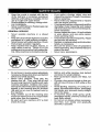
Never direct discharged material toward
anyone.
Avoid
discharging
material
against a wall or obstruction.
Material
may ricochet back toward the operator.
Stop the blades when crossing gravel
surfaces.
_WARNING:
Do not coast down a hill in
neutral, you may lose control of the tractor.
-
Do not operate machine without the entire grass catcher, discharge chute, or
other safety devices in place and working.
Slowdown
before turning.
Never leave a running machine unattended.
Always turn off blades, set
parking brake, stop engine, and remove
keys before dismounting.
Disengage
blades when not mowing.
Shut off engine and wait for all parts to
come to a complete stop before cleaning
the machine, removing the grass catcher,
or unclogging the discharge chute.
Operate machine only in daylight or good
artificial light.
Do not operate the machine while under
the influence of alcohol or drugs.
"Watch for traffic when operating near or
crossing roadways.
Use extra carewhen loading or unloading
the machine into a trailer or truck.
_WARNING:
Tow only the attachments
that are recommended
by and comply with
specifications
of the manb'facturer
of your
tractor. Use common sense when towing.
Operate only at the lowest possible speed
when on a slope. Too heavy of a load, while
on a slope, is dangerous.
Tires can lose
traction with the ground and cause you to
lose control of your tractor.
,
°
,
_WARNING:
Engine exhaust,
some of
its constituents,
and certain vehicle components contain or emit chemicals known to the
State of California to cause cancer and birth
defects or other reproductive
harm.
•
•
°
_WARNING:
Battery posts, terminals and
related accessories
contain lead and lead
compounds, chemicals known to the State of
California to cause cancer and birth defects
or other reproductive
after handling.
!. GENERAL
•
•
•
°
•
,
•
harm. Wash
°
•
hands
°
OPERATION
Read, understand, and follow all instructions on the machine and in the manual
before starting.
Do not put hands or feet near rotating
parts or under the machine. Keep clear
of the discharge opening at all times.
Only allow responsible
adults, who are
familiar with the instructions, to operate
the machine.
•
°
Clear the area of objects such as rocks,
toys, wire, etc., which could be picked
up and thrown by the blades.
Be sure the area is clear of bystanders
before operating. Stop machine if anyone
enters the area.
Never carry passengers°
Do not mow in reverse unless absolutely
necessary. Always look down and behind
before and while backing.
3
Aiwayswear
eye protection when operating machine.
Data indicates that operators,
age 60
years and above, are involved in a large
percentage of riding mower-related
injuries. These operators should evaluate
their ability to operate the riding mower
safely enough to protect themselves and
others from serious injury.
Follow the manufacturer's
recommendation for wheel weights or counterweights.
Keep machine free of grass, leaves or
other debris build-up which can touch hot
exhaust / engine parts and burn. Do not
allow the mower to plow leaves or other
debris which can cause build-up to occur. Clean any oil or fuel spillage before
operating or storing the machine° Allow
machine to cool before storage.
II. SLOPE
OPERATION
•
Slopes are a major factor related to loss of
control and tip-over accidents, which can
result in severe injury or death. Operation
on all stopes requires extra caution.
If you
cannot back up the slope or if you feel uneasy
on it, do not mow it.
o Mow up and down slopes, not across.
, Watch for holes, ruts, bumps, rocks, or
other hidden objects.
Uneven terrain
could overturn the machine.
Tall grass
can hide obstacles
, Choose a low ground speed so that you
will not have to stop or shift while on the
slope.
° Do not mow on wet grass. Tires may lose
traction.
•
•
•
.
,
,
°
°
Avoid starting, stopping, or turning on a
slope. Ifthe tires Iosetraction,
disengage
the blades and proceed slowly straight
down the slope.
Keep all movement on the slopes slow
and gradual.
Do not make sudden
changes in speed or direction, which
could cause the machine to roll over.
Use extra care while operating machine
with grass catchers or other attachments;
they can affect the stability of the machine. Do no use on steep slopes.
"_
Do not try to stabilize the machine by
putting your foot on the ground.
Do not mow near drop-offs,
ditches,
or embankments.
The machine could
suddenly roll over if a wheel is over the
edge or ff the edge caves in.
°
=
•
SAFE HANDLING
,
•
OF GASOLINE
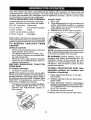
To avoid personal injury or property damage, use extreme care in handling gasoline.
Gasoline is extremely flammable
and the
vapors are explosive.
° Extinguish all cigarettes, cigars, pipes,
and other sources of ignition.
•
Use only approved gasoline container.
•
Never remove gas cap or add fuel with
the engine running. Allow engine to cool
before refueling.
,
Never fuelthe machine indoors.
•
Never store the machine or fuel container
where there is an open flame, spark, or
pilot light such as on a water heater or
other appliances.
•
Never fill containers inside a vehicle or
on a truck or trailer bed with plastic liner.
Always place containers on the ground
away from your vehicle when filling.
° Remove gas-powered
equipment from
the truck or trailer and refuel it on the
Tragic accidents can occur if the operator
is not alert to the presence
of children.
Children are often attracted to the machine
°
Tow only with a machine that has a hitch
designed for towing. Do not attach towed
equipment except at the hitch point.
Followthe manufacturer's recommendation for weight limits for towed equipment
and towing on slopes.
Never allow children or others in or on
towed equipment°
On slopes, theweight ofthetowed equipment may cause loss of traction and loss
of control
Travel slowly and allow extra distance to
stop.
V. SERVICE
Ill. CHILDREN
and the mowing activity.
that children will remain
saw them,
Use extra care when approaching
blind
corners, shrubs, trees, or other objects
that may block your view of a child,
IV. TOWING
Always keep the machine in gear when
going down slopes. Do not shift to neutral
and coast downhill.
•
Never carry children,
even with the
blades shut off. They may fall off and
be seriously injured or interfere with safe
machine operation. Children who have
been given rides in the past may suddenly
appear in the mowing area for another
ride and be run over or backed over by
the machine.
Never allow children to operate the machine.
Never assume
where you last
Keep children out of the mowing area
and in the watchful care of a responsible
adult other than the operator.
Be alert and turn machine off if a child
enters the area.
Before and while backing, look behind
and down for small children.
ground. If this is not possible, then refuel
such equipment with a portable container,
rather than from a gasoline dispenser
no_le.
4
•
o
o
Keep the nozzle in contact with the rim
of the fuel tank or container opening at
all times until fueling is complete. Do not
use a nozzle lock-open device.
If fuel is spilled on clothing, change clothing immediately.
Never overfill fuel tank_ Replace gas cap
and tighten securely.
°
o
°
GENERALSERVICE
°
•
,
,
•
•
°
°
°
Never operate
machine
in a closed
area.
Keep all nuts and bolts tightto be sure the
equipment is in safe working condition.
Nevertamperwithsafetydevices.Check
their proper operation regularly.
Keep machine free of grass, leaves, or
other debris build-up.
Clean oil or fuel
spillage and remove any fuel-soaked debris. Allow machine to cool before storing.
•
•
°
•
Do not mow in reverse unless absolutely
necessary. Always look down and behind
before and while backing.
Never carry children,
even with the
blades shut off. They may fall off and
be seriously injured or interfere with safe
machine operation. Children who have
been given rides in the past may suddenly
appear in the mowing area for another
ride and be run over or backed over by
the machine.
Keep children out of the mowing area
and in the watchful care of a responsible
adult other than the operator.
Be alert and turn machine off if a child
enters the area.
,
Before and while backing, look behind
and down for small children.
°
Mow up and down slopes (15 ° Max), not
across.
Choose a low ground speed so that you
will not have to stop or shift while on the
slope.
Avoid starting, stopping, or turning on a
slope. Ifthetires lose traction, disengage
the blades and proceed slowly straight
down the slope.
If machine
stops while going uphill,
disengage blades, shift into reverse and
back down slowly.
Do not turn on slopes unless necessary,
and then, turn slowly and gradually
downhill, if possible.
°
°
°
•
5
If you strike a foreign object, stop and
inspectthe machine. Repair, if necessary,
before restarting.
Never make any adjustments or repairs
with the engine running.
Check grass catcher components and the
discharge chute frequently and replace
with manufacturer's
recommended parts,
when necessary.
Mower blades are sharp. Wrap the blade
or wear gloves, and use extra caution
when servicing them.
Checkbrake operationfrequently.
Adjust
and ser,_ice as required.
Maintain or replace safety and instruction
labels, as necessary.
Be sure the area is clear of bystanders
before operating. Stop machine ifanyone
enters the area.
Never carry passengers.
PRODUCT
SPECiFICATiONS
rGasoline Capacity
and Type:
3 Gallons
Unleaded Regular
Oil Type
(API-SG-SL):
SAE 10W30(above 32°F)
SAE 5W30(below 32°F)
Oil Capacity:
64 oz.
Spark
Ground
Plug:
Speed
Congratulations on making a smart purchase.
Your new Craftsman® product is designed
and manufactured for years of dependable
operation, But like allproducts, it may require
repair from time to time. That's when having
a Repair ProtectionAgreement can save you
money and aggravation.
Purchase a Repair Protection Agreement
now and protect yourself from unexpected
hassle and expense°
Champion
RC12YC
(Gap: .030")
Forward:
Reverse:
5°2
2.9
Charging System:
I5 Amps @ 3600 RPM
Battery:
AmPiHr:
Min. CCA:
Case size:
Blade Bolt
REPAIR PROTECTION
AGREEMENTS
Here's what's
28
230
U1R
45-55 Ft. Lbs.
in the Agreement:
•
Expert service by our 12,000 profesional
repair specialists.
•
Unlimited service and no charge for parts
and labor on all covered repairs.
•
Product
replacement
product can't be fixed.
Torque:
CONGRATULATIONS
on your purchase of
a new tractor. It has been designed, engineered and manufactured to give you the best
possible dependability
and performance.
Should you experience any problem you cannot easily remedy, please contact a Sears or
other qualified service center. We have competent, welt-trained representatives
and the
proper tools to service or repair this tractor.
Please read and retain this manual. The
instructions
will enable you to assemble
and maintain your tractor properly° Always
observe the "SAFET_
RULES".
included
if your
covered
Discount of 10% from regular price of
service and service-related
parts not
covered by the agreement; also, 10% off
regular price of preventive maintenance
check.
Fast help by phone - phone support
from a Sears representative
on products
requiring imhome repair, plus convenient
repair scheduling.
Once you purchase
the Agreement,
a
simple phone call is all that it takes for you
to schedule service. You can call anytime
day or night, or schedule a service appointment online.
CUSTOMER
RESPONSIBILITIES
• Read and observe the safety rules.
• Follow a regular schedule in maintaining,
caring for and using your tractor.
• Follow the instructions under "Maintenance" and "Storage" sections of this
owner's manual.
Sears has over 12,000 professional
repair
specialists,
who have access to over 4.5
million quality parts and accessories. That's
the kind of professionalism
you can count on
to help prolong the life of your new purchase
for years to come. Purchase your Repair
Protection Agreement today!
_WARNING:
This tractor isequipped with
an internalcombustionengine and should not
be used on or near any unimproved forestcovered, brush-covered or grass-covered
land unless the engine's exhaust system is
equipped with a spark arrester meeting applicable local orstate laws (if any), if a spark
arrester is used, it should be maintained in
effective working order by the operator.
In thestate of California the above isrequired
by law (Section 4442 of the California Public
Resources Code). Other states may have
similar laws. Federal laws apply on federal
tands. A spark arrester for the muffler is
availablethrough your nearest Sears service
center (See REPAIR PARTS manual).
Some limitations and exclusions
apply.
For prices and additional information call
1-800-827-6655.
SEARS INSTALLATION
SERVICE
For Sears professional installation of home
appliances, garage door openers, water
heaters, and other major home items, in the
U.S.A. call 1-800-4-MY-HOME®
6
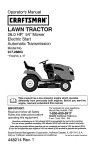
Mower
©
Mower Front Wheel
(2) Rear _-,'x_,,
Lift Link _-j
(5) 1-3/16
O.D, Washers
(1) Shoulder Bolt
Assemblies _
(1) %1/40.D.
Washer
(1) Small
Retainer Springs
(1) Front
Lift Link
Assembly
(1) Wheel
(1) 3/8-1 6
I.ocknut
(5) Large
Retainer Springs
(1) Oil Drain Tube
If Equipped
Keys
11) Anti-Sway Bar
(1) 3/40.D.
Washers
121Keys
(1) Small Retainer
Springs
7
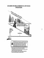
Slope Sheet
'(our new tractor has been assembled
at the factory with exception of those parts left
unassembted
for shipping purposes.
To ensure safe and proper operation of your tractor
all parts and hardware you assemble must be tightened securely.
Use the correct tools
as necessary to ensure proper tightness.
TOOLS REQUIRED FOR ASSEMBLY
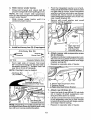
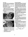
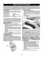
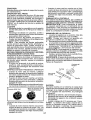
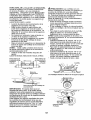
ADJUST SEAT
A socket wrench
easier. Standard
1. Sit in seat.
set will make assembly
wrench sizes are listed.
(2) 7/t6" wrenches
Utility knife
(1) 1/2" wrench
(!) 3/4" wrench
Tire pressure
Pliers
(1) 3/4" socket w/drive
(!) 9/16" wrench
2.
gauge
3,
Lift up adjustment lever (A) and slide seat
until a comfortable
position is reached
which allows you to press clutch/brake
pedal all the way down.
Release lever to lock seat in position.
ratchet
Flashlight
When right or left hand is mentioned in this
manual, itmeanswhenyouare
inthe operating
position (seated behind the steering wheel).
TO
REMOVE
TRACTOR
FROM
CARTON
UNPACK
•
•
,
•
CARTON
Remove all accessible loose parts and
parts cartons from carton.
Cut along dotted lines on all four panels of carton, Remove end panels and
lay side panels flat.
Remove mower and packing materials.
Check for any additional loose parts or
cartons and remove.
BEFORE
REMOVING
FROM SKID
TO CHECK
t.
NOTE: You may now roll your tractor off the
skid, Follow the appropriate instruction below
to remove the tractor from the skid.
WARNING;
Before starting, read, understand and follow all instructions
in the
Operation section of this manual. Be sure
tractor is in a well-ventilated
area. Be sure
the area in front of tractor is clear of other
people and objects,
TRACTOR
TO ROLL TRACTOR OFF SKID (See
Operation section for location and
function of controls)
BATTERY
Lift hood to raised
position.
NOTE: If this battery is put into service after
month and year indicated on label (label is
located between terminals) charge battery
for minimum of one hour at 6-10 amps. (See
"BATTERY" in Maintenance
section of this
manual for charging
o
1. Raise attachment
est position.
2.
instructions),
Release parking
brake pedal.
lift lever to its highbrake by depressing
3.
Place freewheel control in disengaged
position to disengage transmission
(See
'_TOTRANSPORT"
in the Operation section of this manual).
4, Roll tractor forward off skid°
For battery and batter] cable installation
see "REPLACING
BATTERY"
in the
"Service and Adjustments"
section in
this manual.
Continue
abe!
8
with the instructions
that follow.
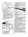
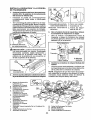
TO INSTALL
MOWER
2_
1, Set Parking Brake Lever (P)And Lower
Attachment
Lift Lever (N),
, Depress clutch/brake
down and hold.
,
Assemble front gauge wheel (W) to
front of mower.
pedal all the way
Pull parking brake lever (P) up and hold,
release pressure from clutch/brake pedal,
then release parking brake lever. Pedal
should remain in brake position.
Make
sure parking brake will hold tractor secureo
Ho Front Mower Bracket
X. Shoulder Bolt
W. Front Gauge Wheel
Yo 11/40oD. Washer
Zo 3/8-16 Locknut
3. Turn steering wheel left and position
mower.
, Turn steering wheel to the left as far as it
willgoand position mower on rightside of
tractorwith deflector shield (Q) to the right.
_CAUTION:
Lift lever (N) is spring loaded.
Have a tight grip on lift lever, lower it slowly
and engage in lowest position. Lift lever is
located on left side of fender.
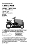
Front
Transaxle
Q, Deflector
Shield
N, Lift Lever
A.
B,
C.
D.
Eo
E
Ho
i. Left Side Rear Mower Bracket
K. Belt Tension Rod
Mower Side Suspension Arms
Retainer Spring
Rear Lift Link(s)
Right Side Rear Mower Bracket
Front Lift Link Assembly
Front Suspension Bracket
Front Mower Bracket
L. Locking Bracket
M o Engine Clutch Pulley
Q, Deflector Shield
S. Anti-Sway Bar
W, Front Gauge Wheel
9
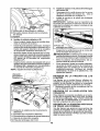
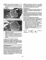
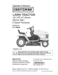
4. Slide mower
•
under tractor.
,
Bring belt forward and check belt for
proper routing in all mower pulley grooves.
NOTE: Be sure mower side suspension
arms (A) are pointing forward before sliding
mower under tractor.
•
Slide mower under tractor
centered under tractor.
until
it is
,
Pivot the integrated washer end of antisway bar (S) towards mower deck bracket
on right side of mower. Insert integrated
washer end of bar into hole in rear mower
bracket (D). Move mower as needed to
insert integrated washer end of bar into
rear mower bracket (D).
Secure with small washer and small
retainer spring as shown.
Right Side Rear
Mower Bracket
S. Anti-Sway Bar
T. Transaxle Bracket
B.
=
Install anti-sway
bar (S) (If equipped)
Anti-Sway Bar (S)
..dTowards
6. Attach mower side suspension
(A) to chassis,
Towards
Mower
Deck _.
....... ,ii,i,,,i,i i_
90 ° End
•
NOTE:
,
Position front hole in side suspension arm
(A) over pin on outside of tractor chassis
and secure with large washer and large
retainer spring (B).
°
Repeat on opposite
Integrated Washer End
From right side of mower, first insert
90 ° end of anti-sway bar (S) into hole in
transaxle bracket (T), located near left
rear tire in front of transaxle.
Flashlight
arms
side of tractor.
may be helpful.
Bar
(s)
Transaxle Bracket (T)
Located Between Rear Tires
A. Mower Side Suspension Arms
BoRetainer Spring
D. Right Side Rear Mower Bracket
7.
Attach
•
Insert rod end of rear lift link (C) into hole
(U) in tractor lift shaft suspension
arm
and pivot link down to mower.
°
Lift rear corner of mower and position slot
in link assembly over pin on rear mower
bracket (D) and secure with large washer
and large retainer spring.
•
Repeat
T. Transaxle Bracket
NOTE: Depending on model, bracket (3")may
be differentthanshown buthole foranti-"sway
bar Will be in same position/location,
10
rear lift links (C)
on opposite
side of tractor°
9
•
InstallBeltOn Engine Clutch Pulley (M)
Disengage belt tension rod (K) from
locking bracket (L).
• Insta!lbelt onto engine clutch pulley (M).
IMPORTANT: Check belt for proper routing in all mower pulley grooves and under
mandrel covers.
%.
\\
\
C. Rear Lift Link(S)
D. Right Side Rear Mower Bracket
U. Hole
8
•
Attach front link (E)
"Purnsteering wheel to position wheels
straight forward.
• From front of tractor, insert rod end of
front link (E) through front hole in tractor
front suspension bracket (F).
. Movetoleftsideofmowerandandinsert
large retainer spring (G) through hole in
front link (E) behind front suspension
bracket (F),
.
Insert other end of link (E) into hole in
front mower bracket (H) and secure with
washer and small retainer spring (J).
NOTE: Requires deck lifting.
Clutch Pulley
•
Engage belt tension
bracket (L).
rod (K) on locking
_CAUTION:
Belt tension rod is spring
loaded. Have a tight grip on rod and
engage slowly°
o
Raise attachment lift lever to highest
position.
• If necessary, adjustgaugewheels before
operating mower as shown in the owner's/
operator's manual. Check gaugewheels,
deck level and rake settings.
CHECK TIRE PRESSURE
The tires on your tractor were overinflated
at the factory, for shipping purposes. Correct
tire pressure is important for best cutting
performance.
• Reducetire pressure to PSI shown ontires.
\
!
CHECK DECK LEVELNESS
For best cutting results, mower housing
should be properlyleveled. See "TO LEVEL
MOWER" in the Service and Adjustments
section of this manual.
CHECK FOR PROPER
ALL BELTS
POSITION
OF
See the figures that are shown for replacing
motion and mower blade drive belts in the
Service and Adjustments sectionofthismanuaL Verifythatthe belts are routed correctly.
CHECK BRAKE SYSTEM
After you learn how to operate your tractor,
check to see thatthe brake is operating pro p_
erlyo See '°TOCHECK BRAKE" inthe Service
and Adjustments section of this manual.
/
E,
E
G.
H_
J.
M.
Front Lift Link Assembly
Front Suspension Bracket
Large Retainer Spring
Front Mower Bracket
Small Retainer Spring
Engine Clutch Pulley
1I
_'CHECKLIST
Before you operate your new tractor, we
wish to assure that you receive the best
performance
and satisfaction
from this
Quality Product.
Please review the following checklist:
J All assembly
instructions
have been
completed.
_/No remaining loose parts in carton.
Battery
is properly
prepared
and
charged.
Seat is adjusted comfortably
and tightened securely.
J All tires are properly inflated° (For shipping purposes, the tires were overinflated
at the factory).
v" Be sure mower deck is properly leveled
side-to-sideifront-to-rear
for best cutting
results. (Tires must be properly inflated
for leveling).
d _ Check mower and drive belts, Be sure
they are routed properly around pulleys
and inside all belt keepers.
J" Check wiring.
See that all connections
are still secure and wires are properly
clamped.
Before driving tractor, be sure freewheel
control is in "transmission engaged" position (see 'To Transport" in the Operation
section of this manual).
While learning how to use your tractor, pay
extra attention to the following
important
items:
J Engine oil is at proper level°
#' Fueltank is filled with fresh, clean, regular
unleaded gasoline.
J" Become familiar with al! controls, their
location and function.
Operate them
before you start the engine.
Be sure brake system is in safe operating
conditiom
J
Be sure Operator Presence System and
Reverse Operation System (ROS) are
working properly (See the Operation and
Maintenance
sections in this manual).
it is important to purge the transmission
before operating your tractor for the first
time. Follow proper starting and transmission purging instructions
(See 'qro
START ENGINE" and "PURGE TRANSMISSION"
manual).
in the Operation
section of this
12
These symbols may appear on your tractor or in literature
Learn and understand their meaning.
R
N
H
L
REVERSE
NEUTRAL
HIGH
LOW
CHOKE
supplied
FAST
with the producL
S_..OW
IGNITION SWITCH
ENGINE OFF
LIGHTS ON
REVERSE
OPERATION
SYSTEM (ROS)
FUEL
ATTACHMENT
CLUTCH DISENGAGED
ENGINE ON
eATTERY
ENGINE START
REVERSE
ATTACHMENT
CLUTCH ENGAGED
PARKING BRAKE
FORWARD
DANGER, KEEP HANDS
AND FEET AWAY
MOWER HEIGHT
CRUISE CONTROL
KEEP AREA CLEAR
MOWER LIFt*
CLUTCH/BRAKE
PEDAL
SLOPE HAZARDS
(SEE SAFETY RULES SECTION)
DANGER indicates a hazard which, If not avoided,
will result in death or serious injury.
FREE WHEEL
(Automatic
Models only)
WARNING indicatesa hazard which, if not avoided,
could result in death or serious Injury.
CAUTION indicatesa hazard which, if not avoided,
might result in minor or moderate Injury.
CAUTION when used without the alert symbol,
indicatesa situation that could result in damage
to the tractor and/or engine.
Failure to follow instructions
could result in serious injury or
death. The safety alert symbol
is used to identify safety information about hazards which can
result in death, serious injury
and/or properbj damage.
HOT SURFACES indicates a hazard which,
if not avoided, could result in death, serious injury
and/or property damage,
FIRE indicatesa hazard which,if not avoided,
could result in death, serious injury and/or
property damage.
13
KNOW YOUR TRACTOR
READ THIS OWNER'S
TRACTOR
MANUAL
AND SAFETY
RULES
BEFORE
OPERATING
YOUR
Compare the illustrations with your tractor to familiarize yourself with the locations
various controls and adjustments.
Save this manual for future reference.
Our tractors conform
American
to the applicable safety standards
National Standards Institute,
(A) ATTACHMENT LIFT LEVER - Used to
raise and lower the mower or other attachments mounted to your tractor.
(H) LIGHT SWITCH
on and off.
of
of the
- Turns the headlights
(B) BRAKE PEDAL - Used for braking the
tractor and starting the engine,
(J) CRUISE CONTROL LEVER-Used
to set
forward movement of tractor at desired speed
without holding the forward drive pedal.
(C) PARKING BRAKE - Locks clutch/brake
pedal into the brake position.
(K) FORWARD
DRIVE PEDAL
forward movement of tractor,
(D) THROTTLE
engine speed.
(L) REVERSE
DRIVE PEDALreverse movement of tractor.
CONTROL-
Used to control
- Used for
Used
for
(E) ATTACHMENT
CLUTCH SWITCH
-Used to engage the mower blades, or
other attachments mounted to your tractor.
(M) FREEWHEEL CONTROLDisengages
transmission
for pushing or slowly towing
the tractor with the engine off.
(F') IGNITION SWITCH - Used for starting
and stopping the engine.
(N) CHOKECONTROLa cold engine.
(G) REVERSE OPERATION
SYS'rEM
(ROS) "ON" POSITION - Allows operation
of mower orother powered attachment while
in reverse,
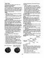
(P) SERVICE REMINDER / HOUR METER
- Indicates when service is required for the
engine and mower.
14
Usedwhen
starting
The 0Peration of any tractor can resultin foreign 0bjects thrown into_
[_,,,%=,=_] the eyes, which can result in severe eye damage. Always wear safety
glasses or eye shields while operating your tractor or performing any
adjustments or repairs. We recommend standard safety glasses or a
wide vision safety mask worn over spectacles.
HOW TO USE YOUR TRACTOR
TO SET PARKING
NOTE:
Failure to move throttle control
between half and full speed (fast) position, before stopping, may cause engine
to "backfire".
BRAKE
"Your tractor is equipped
with an operator
presence sensing switch. When engine is
running, any attempt by the operator to leave
the seat without first setting the parking brake
will shut off the engine.
1. Depress brake pedal (B) allthe way down
and hold.
2.
• Turn ignition key (F) to "STOP" position
and remove key° Always remove key when
leaving tractor to prevent unauthorized
use,
- Never use choke (N) to stop engine.
IMPORTANT:
Leaving the ignition switch in
any position other than "STOP" will cause
the battery to discharge and go dead.
NOTE: Under certain conditions when tractor
Pull parking brake lever (C) up and hold,
release pressure from brake pedal (B),
then release parking brake lever. Pedal
should remain in brake position.
Make
sure parking brakewill hold tractor secure.
is standing idle with the engine running, hot
engine exhaust gases may cause "browning" of grass. To eliminate this possibility,
always stop engine when stopping tractor
on grass areas.
_CAUTION:
Always stop tractor completely, as described above, before leaving
the operator's position.
STOPPING
MOWER BLADES• 'To stop mower blades, push attachment
clutch switch into disengaged position (O)_
(!) Attachment
Clutch Switch
Pull Out To "Engage"
TO USE THROTTLE
CONTROL
(D)
Always operate engine at full speed (fast).
• Operating engine at less than flJll speed
(fast) reduces engine's operating efficiency.
• Full speed (fast) offers the best mower
performance_
(O) Push-ln to
"Disengaged"
STOPPING
GROUND
DRIVE
TO USE CHOKE
• To stop ground drive, depress brake pedal
all the way down.
ENGINE
CONTROL
(N)
Use choke control whenever you are starting
a cold engine_ Do not use to start a warm
engine.
• To engage choke control, pull knob out.
Slowly push knob in to disengage.
-
• Move throttle control (D) between half and
full speed (fast) position.
15
TO MOVE
FORWARD
AND BACKWARD
The cutting height range is approximately
1"
to 4". The heights are measured from the
ground to the bladetip with the engine not running, These heights are approximate and may
vary depending upon soil conditions, height
of grass and types of grass being mowed.
• The average lawn should be cut to approximately
2_!/2" during the coot season and to over 3" during hot months.
For healthier and better looking lawns,
mow often and after moderate growth,
• For best cutting performance,
grass over
6 inches in height should be mowed
twice. Make the first cut relatively high;
the second to desired heighL
TO ADJUST GAUGE WHEELS
The direction and speed of movement is
controlled by the forward and reverse drive
pedals.
1. Start tractor
and release
parking
brake.
2. Slowty depress forward (K) orreverse(L)
drive pedal to begin movement. Ground
speed increases the further down the
pedal is depressed.
Gauge wheels are properly adjusted when
they are slightly offthe ground when mower
is at the desired cutting height in operating
position. Gauge wheels then keep the deck
_n proper position to help prevent scalping
in most terrain conditions_
TO USE CRUISE CONTROL
The cruise control feature can be used for
forward travel only.
SYSTEM CHARACTERISTICS
The cruise control should only be used
while mowing or transporting on relatively
smooth, straight surfaces. Other conditions
such as trimming at slow speeds may cause
the cruise control to disengage. Do not use
the cruise control on slopes, rough terrian
or while trimmimg or turning.
• With forward drive pedal depressed to
desired speed, pull cruise control lever
(J) up and hold while lifting your foot off
the pedal, then release the lever.
To disengage the cruise control, depress the
brake pedal, tap on forward drive pedal or
push the cruise control lever down_
TO ADJUST MOWER CUTTING HEIGHT
The position of the attachment lift lever (A)
determines the cutting height.
NOTE: Adjust gauge wheels with tractor on
a flat level surface.
1, Adjust mower to desired cutting height
(See "TO ADJUST MOWER CUTTING
HEIGHT" in this section of manual).
2. With mower in desired height ofcutposition, gauge wheels should be assembled
so they are slightly off the ground. Install
gauge wheel in appropriate hole. Tighten
securely.
3. Repeat for all, installing gauge wheel in
same adjustment
hole.
TO OPERATE
MOWER
Your tractor is equipped with an operator
presence sensing switch _Any attempt by the
operator to leave the seat with the engine
running and the attachment clutch engaged
wilt shut off the engine° You must remain
fully and centrally positioned in the seat to
prevent the engine from hesitating or cutting
offwhen operating your equipment on rough,
rolling terrain or hills.
1_ Select desired height of cut with attachment lift lever.
2. Start mower blades by engaging attachment clutch control.
Put attachment lift lever in desired cutting
height slot.
16
TO STOP MOWER
, Disengage
TO OPERATE ON HILLS
BLADES
attachment
clutch control.
_WARNING:
Do not drive up or down
hillswith slopes greater than 15° and do not
drive across any slope. Use the slope guide
provided at the back of this manual.
• Choose the slowest speed before starting
up or down hills.
• Avoid stoppingor changing speed on hills.
o If stopping is absolutely necessary, push
brake pedal quickly to brake position and
engage parking brake.
, Torestart movement, slowly release parking brake and brake pedal.
• Slowly depress appropriate drive pedal to
slowest setting,
o Make all turns slowly.
_CAUTION:
Do not operate the mower
without either the entire grass catcher, on
mowers so equipped, or the deflector shield
(S) in place.
REVERSE OPERATION SYSTEM (ROS)
Your tractor is equipped
with a Reverse
Operation System (ROS). Any attempt by
the operator to travel in the reverse direction
with the attachment clutch engaged will shut
off the engine unless ignition key is placed
in the ROS "ON" position.
TO TRANSPORT
When pushing or towing your tractor, be
sure to disengage transmission
by placing
freewheel control in freewheeling
position.
Free wheel control is located at the rear
drawbar of tractor.
• Raise attachment
lift to highest position
with attachment lift control.
° Pullfreewheel
control out and into the slot
and release so it is held in the disengaged
position.
° Do not push or tow tractor at more than
two (2) MPH.
° To reengagetransmission,
reverse above
procedure°
_WARNING:
Backing up with the attachment clutch engaged while mowing
is strongly discouraged.
Turning the ROS
"ON", to allow reverse operation with the
attachment clutch engaged, should only
be done when the operator decides it is
necessary to reposition the machine with
the attachment engaged. Do not mow in
reverse unless absolutely necessary,
USING THE REVERSE
SYSTEM
OPERATION
Only use if you are certain no children or
other bystanders will enter the mowing area.
I, Depress brake pedal all the way down.
2. With engine running, turn ignition key
counterclockwise
to ROS "ON" position.
3. Look down and behind before and
while backing.
4. Slowly depress reverse drive pedal to
start movement.
5. When use of the ROS is no longer
needed, turn the ignition key clockwise
to engine "ON" position°
ROS "ON" Position
NOTE: To protect hood from damage when
transporting your tractor on a truck or a trailer,
be sure hood is closed and secured to tractor.
Use an appropriate means of tying hood to
tractor (rope, cord, etc.).
TOWING CARTS AND OTHER ATTACHMENTS
Tow only the attachments that are recommended by and comply with specifications
of the manufacturer of your tractor. Use
common sense when towing. Too heavy
of a load, while on a slope, is dangerous.
Tires can lose traction with the ground and
cause you to lose control of your tractor_
Engine "ON" Position
(Normal Operating)
17
SERVICE REMINDER/HOUR
METER
Service reminder shows the total number
of hours the engine has run and flashes to
indicate that the engine or mower needs servicing° When service is required, the service
reminder will flash for two hours. To service
engine and mower, see the Maintenance
section of this manual.
NOTE: Service reminder
runs when the
ignition key is in any position but "STOP".
For acurate reading, be sure key remains
in the "STOP" position when engine is not
running.
BEFORE
CHECK
STARTLING
ENGINE
THE
ENGINE
OiL LEVEL
TO START
The engine in your tractor has been shipped,
from the factory, already filled with summer
weight oil.
1. Check engine oi! with tractor on level
ground.
2.
CAUTION:
Alcohol blended fuels (called
gasohol or using ethanol or methanol) can
attract moisture which leads to separation
and formation of acids during storage. Acidic
gas can damage the fuel system of an engine
while in storage. To avoid engine problems,
the fuel system should be emptied before
storage of 30 days or longer. Drain the gas
tank, start the engine and let it run until the
fuel lines and carburetor are empty. Use fresh
fuel next season. See Storage Instructions
foradditionalinformation
Never use engine
or carburetor cleaner products in the fuel tank
or permanent damage may occur.
ENGINE
When starting the engine for the first time or
if the engine has run out of fuel, it wilt take
extra cranking time to move fuel from the
tank to the engine.
1. Be sure freewheel control is in the transmission engaged positiom
2. Sit on seat in operating position, depress
brake pedal and set parking brake.
3o Move attachment clutch to disengaged
position.
4. Move throttle control to fast position
5. Pull choke control out for a cold engine
start attempt, For a warm engine start
attempt the choke control may not be
needed.
NOTE: Before starting, read the warm and
cold starting procedures below.
6. Insert key into ignition and turn key
clockwise to start position and release
key as soon as engine starts. Do not run
starter continuously for more than fifteen
seconds per minute. If the engine does
not start after several attempts,
push
choke control in, wait a few minutes and
try again. If engine still does not start,
pull the choke control out and retry.
Unthread and remove oil fillcap/dipstick;
wipe oil off. Reinsert the dipstick into the
tube and rest oil fill cap on the tube. Do
not thread the cap ontothe tube. Remove
and read oil level. If necessary, add oil
until "FULE' mark on dipstick is reached.
Do not overfill.
3. For cold weather operation you should
change oil for easier starting (See the oil
viscosity chart in the Maintenance section
of this manual)°
4. To change engine oil, see the Maintenance
section in this manual.
5. Fill fuel tank to bottom of filler neck. Do not
overfill. Use fresh, clean, regularunleaded
gasoline with a minimum of 87 octane.
(Use of leaded gasoline will increase
carbon and lead oxide deposits and reduce
valve life). Do not mix oil with gasoline.
Purchase fuel in quantities that can be used
within 30 days to assure fuel freshness.
WARM WEATHER
and above)
_I_CAUTION:
Wipe off any spilled oil or
fuel. Do not store, spill or use gasoline near
an open flame.
STARTING
(50°F/10°C
7. When engine starts, slowly push choke
control in until the engine begins to run
smoothly_ If the engine starts to run
roughly, pull the choke control out slightly
for a few seconds and then continue to
push the control in slowly°
8. The attachments
and ground drive can
now be used. if the engine does not accept
the load, restart the engine and allow it to
warm up for one minute using the choke
as described above.
IMPORTANT:
When operating in temperatures below 32°F (0°C), use fresh, clean
winter grade gasoline to help ensure good
cold weather starting.
18
COLD WEATHER
STARTING (50°F/10°C
and below)
9, When engine starts, slowly push choke
control in until the engine begins to run
smoothly. Continue to push the choke
control in small steps allowing the engine
to accept small changes in speed and
load, until the choke control is fully in.
If the engine starts to run roughly, pull
the choke control out slightly for a few
seconds and then continue to push the
control in slowly° This may require an
engine warm-up
period from several
seconds to several minutes, depending
on the temperature.
AUTOMATIC
TRANSMISSION
WARM
2.
Disengage
transmission
by placing
freewheel control in disengaged position
(See "TO TRANSPORT"
in this section
of manual).
3. Sitting in the tractor seat, start engine.
After the engine is running, move throttle
control to slow position. Disengage parking brake.
_CAUTION:
At any time, during step 4,
there may be movement of the drive wheels.
4o Depress forward drive pedal to full foF
ward position and holdforfive (5) seconds
and release pedal. Depress reverse drive
pedal to full reverse position and hold
for five (5) seconds and release pedal,
Repeat this procedure three (3) times,
5o Shutoff engine and set parking brake,
6. Engage transmission
by placing freewheel control in engaged position (See
"TO TRANSPORT'
in this section of
manual),
7, Sitting in the tractor seat, start engine.
After the engine is running, move throttle
control to half (1/2) speed. Disengage
parking brake_
& Drive tractor forward for approximately
five feet then backwards
for five feet,
Repeat this driving procedure
three
times.
UP
Before driving the unit in cold weather, the
transmission
should be warmed up as follows:
i, Be sure the tractor is on level ground,
2. Release the parking brake and let the
brake slowly return to operating position.
3. Allow one minute for transmission
to
warm up. This can be done during the
engine warm up period.
4. The attachments
can be used during the
engine warm-up period after the transmission has been warmed up and may require
the choke control be pulled out slightly.
NOTE: If at a high altitude (above 3000
feet) or in cold temperatures
(below 32°F)
the carburetor fuel mixture may need to be
adjusted for best engine performance
(see
'qO ADJUST CARBURETOR"
in the Service
and Adjustments
PURGE
section
Your transmission is now purged and now
ready for normal operation,
MOWING TIPS
of this manual),
• Tire chains cannot be used when the
mower housing is attached to tractor.
o Mowershould
be properly leveled for best
mowing performance.
See "TO LEVEL
MOWER HOUSING"
in the Service and
TRANSMISSION
&CAUTION:
Never engage or disengage
freewheel lever while the engine is running,
Adjustments
section of this manual.
• The left hand side of mower should be
used for trimming.
• Drive so that clippings are discharged onto
the area that has already been cut. Have
the cut area to the right of the tractor. This
will result in a more even distribution of
clippings and more uniform cutting.
o When mowing large areas, start by turning
to the right so that clippings will discharge
away from shrubs, fences, driveways,
etc. After one or two rounds, mow in the
opposite direction making left hand turns
until finished.
To ensure proper operation and performance,
it is recommended
that the transmission be
purged before operating tractor for the first
time, This procedure will remove any trapped
air inside the transmission
which may have
developed during shipping of your tractor,
IMPORTANT:
Should your transmission
require removal for service or replacement,
it should be purged after reinstallation before
operating the tractor.
1. Place tractor safely on a level surface that is clear of objects and open - with
engine off and parking brake set.
19
ill
o If grass is extremely
tall, it should be
mowed twice to reduce load and possible
fire hazard from dried clippings.
Make
first cut relatively high; the second to the
desired heighL
, Do not mow grass when it is wet. Wet
grass will plug mower and leave undesirable clumps.
Allow grass to dry before
mowing°
• Always operate engine at full throttle
when mowing
to assure better mowing performance
and proper discharge
of material.
Regulate ground speed by
selecting a low enough speed to give the
mower cutting performance as well as the
quality of cut desired.
° When operating
attachments,
select a
ground speed that will suit the terrain and
give best performance
of the attachment
being used.
2O
......................... :'_Fo._- _R_
MAINTENANCE
_C.
S
SCHEDULE
USE
HOURS
I
,
I
I
I
ii
,
I
........
i,l,l,,i,,,,,,i,,,,,i,_,l_UU,_,_
_w.v
=_
EvE.'_ _vE"v Ev_.v SE'_0R'_
SS
_OD S_SO. STORAGE
HOURS
HOURS
HOURS
i1,_1
Check Brake Operation
Check Tire Pressure
RT Check operaior
............................................
PresenCe
i
Check for Loose Fasteners
C
ChectdReplace
T
Lubrication
O
Check............
Battery
R
Clean
v'
& ROS Syslerns
J i ....
:i
Mower Blades
v'
Chart
Battery
Clean Debris
_
Level
V
'
....
.....
............................
...................
"
end Termlna'fs
Oil Steering Plate
_s
Check Trensaxla Cooling
_J'
CheckMow_rLevefness
C!_,eckV-Belts
Check.Engine Oit Level.
,,,
Ir"_
I!
I
-
-
V"
....
_
. _i.._.
.....
v"
Change Engine Ofi (with o!! fitter)
_
,
J
Change EngineOil(wIIhou!
oil
IIIter)
E
_a
Clean Air FiIter
G Clean Air Screen
................
I _Inspect Muffler/Spark Attester
N Rep_cpO!!FUter 11!e_U!pped)
E
........
vt_
.................................................
Clean Engine Cooltng Fins
=
v'
P,ep_ce Spark Plug
v"
ReplaceAir FitterPaperCartridge
Replace Fuel Filler
GENERAL
,
..............................................
EACH
V q
LUBRICATION CHART
RECOMMENDATIONS
The warranty on this tractor does not cover
items that have been subjected to operator
abuse or negligence. To receive full value
from the warranty, operator must maintain
tractor as instructed in this manual.
Some adjustments will need to be made periodically to properly maintain your tractor.
At least once a season, check to see if
you should make any of the adjustments
described in the Service and Adjustments
section of this manual.
• At least once a year you should replace
the spark plug, clean or replace air filter,
and check blades and belts for wear. A
new spark plug and clean air filter assure
proper air-fuel mixture and help your engine run better and last longer,,
BEFORE
,
Spindle_
(_) Spindle
ark
Zerk
_
Front Wheel
Bearing zerk
_) Steerin_
Sector Gear _/
Front Wheel
Bearing zerk
=
1',
_
Teeth
_._
'_' J _"
_
I
_T_)Engine
%Mandrel
Zerks
(#General Purpose Grease
@Refer to Maintenance "ENGINE" Section
USE
1.
2,
3,
4,
Check engine oil level.
Check brake operation.
Check tire pressure,
Check operator presence and
ROS systems for proper operation,
5_ Check for loose fasteners,
IMPORTANT:
Do not oil or grease the pivot
points which have special nylon bearings.
Viscous lubricants will attract dust and dirt
that will shorten the life of the self-lubricating
bearings. If you feel they must be lubricated,
use only a dry, powdered graphite type lubricant sparingly,
21
TRACTOR
CHECK REVERSE
SYSTEM
Always observe safety rules when performing any maintenance.
BRAKE OPERATION
, Maintain proper air pressure in all tires
(See PSI on tires).
° Keep tires free of gasoline, oil, or insect
control chemicals which can harm rubber.
For best results mower blades must be
sharp. Replace worn, bent or damaged
blades.
A_ CAUTION:
Use only a replacement
blade approved by the manufacturer
of
your tractor. Using a blade not approved
by the manufacturer
of your tractor is
hazardous, could damage your tractor and
void your warranty.
° Avoid stumps, stones, deep ruts, sharp
objects and other hazards that may
cause tire damager
NOTE: To seal tire punctures and prevent
flat tires due to slow leaks, tire sealant
may be purchased from your local parts
dealer_ Tire sealant also prevents tire dry
rot and corrosion.
OPERATOR
PRESENCE
SYSTEM AND
OPERATION
SYSTEM
BLADE
(ROS)
PRESENCE
o When the engine is running, any attempt by the operator to leave the seat
without first setting the parking brake
should shut off the engine.
° When the engine is running and the
attachment clutch is engaged, any attempt by the operator to leave the seat
should shut off the engine.
• The attachment clutch should never operate unless the operator is in the seat.
ROS "ON" Position
REMOVAL
1. Raise mowerto highest position to allow
access to blades,
NOTE: Protect your hands with gloves and/
or wrap blade with heavy cloth.
2. Remove blade bolt by turning counterclockwise.
3. Installnewbladewith
stamped"THIS SIDE
UP" facing deck and mandrel assembly.
IMPORTANT:
To ensure proper assembly,
center hole in blade must align with star on
mandrel assembly.
4. Install and tighten blade bolt securely
(45_55 Ft, Lbs. torque)_
IMPORTANT:
Special blade bolt is heat
Be sure operator presence and reverse
operation systems are working properly,
tf
your tractor does not function as de.o
scribed, repair the problem immediately.
• The engine should not start unless the
brake pedal is fully depressed, and
the attachment clutch control is in the
disengaged
position.
CHECK OPERATOR
SYSTEM
(ROS)
o When the engine is running with the
ignition switch in the engine "ON" position and the attachment clutch engaged,
any attempt by the operator to shift into
reverse should shut off the engine_
• When the engine is running with the
ignition switch in the ROS "ON" position
and the attachment clutch engaged,
any attempt by the operator to shift into
reverse should NOT shut off the engine.
BLADE CARE
If tractor requires more than five (5) feet to
stop at highest speed in highest gear on a
level, dry concrete or paved surface, then
brake must be serviced. (See "TO CHECK
BRAKE" in the Service and Adjustments
section of this manual)°
TIRES
REVERSE
OPERATION
treated.
Mandrel
"
_.._ Assembly
Bl_l_/ade
_\ _Z_._._--_
Blade Bolt
"%'_"_..'.-_..,
,_a_7._ r-
Center Hole
BATTERY
Engine "ON" Position
(Normal Operating)
"{our tractor has a batter/charging
system
which is sufficient for normal use. However,
periodic charging of the battery with an automotive charger will extend its life.
• Keep battery and terminals
° Keep battery
clean.
bolts tight.
• Keep small vent holes open.
, Recharge
22
at 6-10 amperes
for 1 hour.
NOTE: The original equipmentbattery on
your tractor is maintenancefree_ Do not
attemptto open or removecapsor covers_
Adding or checking level of electrolyteis
not necessary.
TO CLEANBATTERYAND TERMINALS
Corrosionanddirt on the batteryandterminalscan causethe batteryto "leak"power.
I. Removeterminalguard.
2. DisconnectBLACK battery cable first
then RED battery cable and remove
batteryfromtractor_
3. Rinsethebatterywithplainwateranddry.
4, Cleanterminalsand batterycable ends
with wire brushuntilbright°
5. Coatterminalswithgreaseor petroleum
jelly.
6o Reinstall battery (See "REPLACING
BATTERY"in the SERVICEAND ADJUSTMENTSsectionof this manual).
TRANSAXLE
COOLING
Keep transaxle free from build-up of dirt and
chaff which can restrict cooling.
V-BELTS
LUBRICATION
Only use high quality detergent oil rated
with API sen_ice classification
SG-SL.
Select the oil's SAE viscosity grade
according to your expected operating
temperature_
GRAOES
F
._.0
c -3o
O
-=o
TEMPERATURE
30
.to
_
[
_,:ml
4tJ
o
RANGE ANTICIPATED
60
1'o
B,
80
_o
8,
fog
_o
.;o
BEFORE NEXT OIL CHANGE
NOTE: Although multi-viscosity
oils
(5W30, IOW30 etc.) improve starting in
cold weather, they wilt result in increased
oil consumption
when used above 32°F.
Check your engine oil level more frequently to avoid possible engine damage from
running low on oil.
Change the oil after every 50 hours of operation or at least once a year if the tractor
is not used for 50 hours in one year.
Check the crankcase oil level before
starting the engine and after each eight
(8) hours of operation.
Tighten oil fill cap/
dipstick securely each time you check the
oil level.
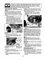
Closed
and
Locked
Drain
4. To open, pull out on the drain valve.
5. After oil has drained completely, close
and lock the drain valve by pushing
inward and turning clockwise until the
pin is in the locked position as shown.
6, Remove the drain tube and replace the
cap onto the end of the drain valve.
7. Refill engine with oil through oil fill dipstick tube, Pour slowly, Do not overfill.
For approximate
capacity see "PRODUCT SPECIFICATIONS"
section of this
manual°
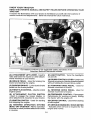
ENGINE
|
Oil Drain Valve
Yellow Ca
Check V-belts for deterioration and wear after
100 hours of operation and replace if necessary. The belts are not adjustable. Replace
belts if they begin to slip from wear.
SAE VISCOSITY
TO CHANGE ENGINE OIL
Determine temperature range expected
before oil change. All oil must meet API
service classification SG-SL.
• Be sure tractor is on level surface.
• Oil will drain more freely when warm°
• Catch oil in a suitable container.
1. Remove oit fill cap/dipstick. Be careful
not to allow dirt to enter the engine
when changing oil,
2, Remove yellow cap from end of drain
valve and insta!l the drain tube onto
the fitting,
3. Unlock drain valve by pushing inward
slightly and turning counterclockwise°
Use gauge on oil fill cap/dipstick for
checking level. Insert dipstick into
the tube and rest the oil fill cap on the
tube. Do not thread the cap onto the
tube when taking reading.
Keep oil
at "FULE line on dipstick,
Tighten cap
onto the tube securely when finished.
ENGINE OIL FILTER
Replace the engine oil filter every season or
every other oil change if the tractor is used
more than 100 hours in one year.
23
AIR FILTER
CLEAN
Your engine wilt not run properly using a
dirty air filter, Service paper cartridge every
two months or every 25 hours of operation,
whichever occurs first.
Air screen must be kept free of dirt and chaff
to prevent engine damage from overheating.
Clean with a wire brush or compressed
airto
remove dirt and stubborn dried gum fibers.
Service paper cartridge more often under
dusty conditions.
Replace the paper cartridge annually, or after
every 100 hours of operation,
TO SERVICE
CLEAN
AiR SCREEN
AiR INTAKE!COOLING
AREAS
To ensure proper cooling, make sure the
grass screen, cooling fins, and other external surfaces of the engine are kept clean
at all times,
Every 100 hours of operation
(more often
under extremely
dusty, dirty conditions),
remove the blower housing and other cooling
shrouds° Clean the cooling fins and external
surfaces as necessary. Make sure the cooling
shrouds are reinstalled,
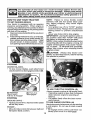
CARTRIDGE
• Replace a dirty, bent, or damaged cartridge. Handle new cartridge carefully; do
not use if the rubber seal is damaged.
NOTE:
Do not wash the paper cartridge
or use pressurized
air, as this will damage
the cartridge.
1. Open door (A) on the blower housing to
access the air cleaner element (B).
NOTE:
Operating the engine with a blocked
grass screen, dirty or plugged cooling fins,
and/or cooling shrouds removed will cause
engine damage due to overheating.
MUFFLER
Inspect and replace corroded muffler and
spark arrester (if equipped) as it could create
a fire hazard and/or damage.
SPARK PLUG(S)
Replace spark plug(s) at the beginning of
each mowing season or after every 100
hours of operation,
whichever occurs first.
Spark plug type and gap setting are shown
in "PRODUCT
SPECIFICATIONS"
section
of this manual,
2o Unhook the latch (C) and remove the
element.
IN-LINE FUEL FILTER
The fuel filter should be replaced once each
season. If fuel filter becomes clogged, obstructing fue! flow tocarburetor, replacement
is required.
1. With engine cool, remove filter and plug
fuel line sections.
2. Place newfuel filter in position in fuel line
with arrow pointing towards carburetor°
3o Be sure there are no fuel fine leaks and
clamps are properly positioned.
4. Immediatelywipe up any spilled gasoline_
3.
Gently tap the paper element to dislodge
dirt.
4. Clean all air cleaner components
of any
accumulated
dirt or foreign
material.
Prevent any dirt from entering the throat
of carburetor.
5o Install cleaned or new element on the
base and secure with latch.
6. Close and latch the door°
Ctam___._
Fuel Filter --------_
24
amp
/_-_-J
CLEANING
, Clean engine, battery, seat, finish, etc.
of all foreign matter.
. Clean debris from steering plate.
Debris can restrict clutch/brake pedal
shaft movement, causing belt slip and
loss of drive.
4o
Pull back the lock collar of the nozzle
adapter and push the adapter onto the
deck washout port at the left end of the
mower deck, Release the lock collar to
lock the adapter on the nozzle.
IMPORTANT:: Tug hose ensuring connection is secure.
5.
Turn the water on.
CAUTION: Avoid all pinch points and
movable parts
Nozzle
_._
Clutchlbrake pedal_0
_\_
_h_
__
•
•
__/_J
Washout Port
I CAUTION:
_''''"
I _
Pinch
Shown I EB Points
6.
IMPORTANT:
Recheck the
certain the area is clear.
We do not recommend using a garden hose
or pressure washer to clean your tractor
unless the engine and transmission
are
covered to keep water out. Water in engine
or transmission
will shorten the useful life of
ur tractor. Use compressed
air or a leaf
ower to remove grass, leaves and trash
from tractor and mower.
position
1.
Drive the tractor to a level, clear spot
on your lawn, near enough to a water
spigot for your garden hose to reach.
IMPORTANT:
Make certain the tractor's
discharge chute is directed AWAY from your
house, garage, parked cars, etc. Remove
bagger chute or mulch cover if attached.
2.
Make sure the attachment clutch control
is in the "DISENGAGED"
position, set
the parking brake, and stop the engine.
area
making
7,
Move the tractor's attachment
clutch
control to the "ENGAGED"
position,
Remain in the operator's
position
with the cutting deck engaged until the
deck is cleaned°
8.
Move the tractor's attachment
clutch
control to the "DISENGAGED"
position. Turn the ignition key to the STOP
position to turn the tractor's engine off.
Turn the water off.
9.
Pull back the lock collar of the nozzle
adapter to disconnect the adapter from
the no_le washout port.
10.
Move the tractor to a dry area, preferably a concrete or paved area. Place
the attachment
clutch control in the
"ENGAGED" position to remove excess
water and to help dry before putting the
tractor away.
PORT
Your tractor's
deck is equipped
with a
washout port on its surface as part of its
deck wash system, tt should be utilized after each use.
3,
sitting in the operator's
on the tractor, re-start the engine,and
place the throttle lever in the Fast ',_"
position.
Keep finished surfaces and wheels
free of all gasoline, oil, etc.
Protect painted surfaces with automotive type wax.
DECK WASHOUT
While
_)AWARNING: A broken or mtssing washout
fitting could expose you or others to thrown
objects from contact with the blade.
• Replace broken or missing washout fitting
immediately, prior to using mower again.
• Plug any holes in mower with bolts and
Iocknuts.
Thread the nozzle adapter (packaged
with your tractor's Operator's
Manual)
onto the end of your garden hose.
25
_
t.
3.
4.
5.
6.
ARNING: TO AVOID SERIOUS INJURY, BEFORE PERFORMING ANY SERVICE OR
ADJUSTMENTS:
Depress clutch/brake
pedal fully and set parking brake.
Place attachment clutch in "DISENGAGED"
position.
Turn ignition key to"STOP"
and remove key.
Make sure the blades and all moving parts have completely stopped.
Disconnect spark plug wire from spark plug and place wire where it cannot come
in contact with plug.
7, Go to other side of mower and disconnect
the suspension
arm and rear lift link.
CAUTION: After rear lift links are disconnected, the attachment lift lever will be spring
loaded. Have a tight grip on lift lever when
changing position of the lever°
8. From right side of mower, disconnect
anti-sway bar (S) from right rear mower
bracket (D)- remove retainer spring and
washer and pull mower toward you until
the bar falls from the hole in bracket.
9. "Parn tractor steering wheel to the left as
far as it will go.
10. Slide mower out from under right side of
tractor_
TO INSTALL MOWER
TO REMOVE
MOWER
1. Place attachment
clutch in "DISENGAGED" position.
2. Lower attachment lift lever to its lowest
position,
3. Disengage belt tension rod (K) from lock
bracket (L).
CAUTION:
Belt tension rod is spring
loaded. Have a tight grip on rod and release
slowly.
4, Remove mower belt from electric clutch
pulley (M) o
5. Disconnect front link (E) from mower remove retainer spring and washer.
6. Go to either side of mower and disconnect mower suspension
arm (A) from
chassis and rear lift link (C) from rear
mower bracket (D) - remove retainer
springs and washers.
Follow procedure
described
in "INSTALL
MOWER AND DRIVE BELT" in the Assembly
section of this manual
26
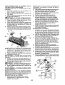
TO LEVEL MOWER
HOUSING
Check adjustment on right side of tractor.
Position any blade so the tip is pointing
straight forward. Measure distance "B" at
front and rear tip of blade
• Before making any necessary adjustments, check that both front plate links
are equal in length.
• If links are not equal in length, adjust
one link to same length as other link.
• To lower front of blade, loosen nut "C"
on both front links an equal number of
turns.
NOTE: Each full turn of nut "C" will
change distance "B" by approximately
3/16".
° When distance "B" is 1/8" to 1/2" lower
at front than rear, tighten nut "D" against
trunnion on both front links.
• To raise front of blade, loosen nut
"D" from trunnion on both front links.
Tighten nut "C" on both front links an
equal number of turns. The two front
links must remain equal in length,
• When distance "B" is 1/8" to 1/2" lower
at front than rear, tighten nut "D" against
trunnion on both front links.
• Recheck side-to-side adjustment°
Adjust the mower while tractor is parked
on level ground or driveway.
Make sure
tires are properly inflated (See "PRODUCT SPECIFICATIONS"
section of this
manual).
If tires are over or underinflated, you will not properly adjust your
mower.
SIDE-TO-SIDE
ADJUSTMENT
, Raise mower to its highest position°
• Measure height from bottom edge of
mower to ground level at front corners
of mower. Distance '_' on both sides of
mower should be the same.
, If adjustment is necessary, make adjustment on one side of mower onlyo
, To raise one side of mower, tighten lift
link adjustment nut on that side,
° To lower one side of mower, loosen lift
link adjustment nut on that side.
NOTE:
Each full turn of adjustment
nut
will change mower height about 3/16".
• Recheck measurements
after adjusting.
Bottom Edge of
Mower to Ground
Bottom Edge of
Mower to Ground
FRONT-TO-BACK
ADJUSTMENT
IMPORTANT:
Deck must be level side-toside. If the following front-to-back
adjustment is necessary, be sure to adjust both
front links equally so mower will stay level
side-to-side.
To obtain the best cutting results, the
mower blades should be adjusted so the
front tip is approximately
!/8" to 1/2" lower
than the rear tip when the mower is in its
4_lghest position.
CAUTION:
Blades are sharp. Protect
your hands with gloves and/or wrap blade
with heavy cloth°
Nut
Front Plate
Assembly
27
Trunnion
TO REPLACE
MOWER
MOWER
DRIVE
BELT
DRIVE BELT REMOVAL
t.
Park tractor on a level surface, Engage
parking brake,
2. Lower attachment lift lever to its lowest
position,
3, Disengage belt tension rod (K) from lock
bOracket (L).
AUTION: Belttension rod is spring loaded, Have afirm grip on rod and release slowly,
4, Remove screws (P) from R.H, and L.H,
mandrel covers and remove covers (Q),
5. Remove any dirt or grass clippings which
may have accumulated around mandrels
and entire upper deck surface,
6. Remove belt from electric clutch pulley
(M), both mandretpulleys
(R) and allidler
pulleys (S),
%
MOWER
DRIVE BELT INSTALLATION
1.
Install belt around both mandrel pulleys
(R) and around idler pulleys (S) as shown,
2. Install belt onto electric clutch pulley (M),
IMPORTANT:
Check beltfor proper routing
in all mower pulley grooves.
3. Reassemble R.H, and L.H, mandrel cow
ors (Q)o Securely tighten all screws,
4. Engage belt tension rod (K) on locking
TO REPLACE
MOTION
DRIVE
BELT
Park the tractor on level surfacer
Engage
parking brake.
For assistance, there is a
belt installation guide decal on bottom side
of left footrest.
BELT REMOVAL
-
1, Remove
mower (See "TO REMOVE
MOWER" in this section of manual).
NOTE: Observe entire motion drive belt and
position of all belt guides and keepers.
2. Remove belt from stationary idler (A) and
clutching idler (B),
3, Remove belt from centerspan idler (C).
4, Pull belt slack toward rear of tractor,
Carefully
remove
belt upwards
from
transmission
input pulley and over cooling fan blades (D) o
5. Remove belt downward
from engine
pulley (E),
6. Slide belt toward rear of tractor, off the
steering plate (F) and remove from tractor.
BELT INSTALLATION
1. Instal! new belt from tractor rearto front,
over the steering plate (F) and above
clutch brake pedal shaft (G).
2, Pull belt toward front of tractor and roll
belt onto engine pulley (E).
3. Pull belt toward rear of tractor, Carefully
work belt down around transmission
cooling fan and onto the input pulley (D),
Be sure belt is inside the belt keeper.
4. Install belt on centerspan idler (C).
5. Install belt through stationary
idler (A)
and clutching idler (B),
6. Make sure belt is in all pulley grooves
and inside all belt guides and keepers,
7. Install mower (See 'qO INSTALL MOWER" in this section of manual).
bracket (L!.
_ CAUTION, Belt tension rod is spring loaded, Have atight grip on rod and engage slowly,
5. Raise attachment
lift lever to highest
position,
I
28
TO CHECK
BRAKE
if tractor requires more than five (5) feet to
stop at highest speed in highest gear on a
level, dry concrete or paved surface, then
brake must be serviced.
You may also check brake by:
1. Park tractor on a level, dry concrete or
paved surface, depress brake pedal all
the way down and engage parking brake.
2, Disengage
transmission
by placing
freewheel
control in "transmission
disengaged" position. Pull freewheel control
out and into the slot and release so it is
held in the disengaged
position.
The rear wheels must lock and skid when
you try to manually push the tractor forward.
If the rear wheels rotate, then the brake
needs to be serviced, Contact a Sears or
other qualified
FRONT
service
WHEEL
center.
TOE-IN/CAMBER
Your new tractor front wheel toe-in and camber is set at the factory and is normal° The
frontwheet toe-in and camber are not adjustable. If damage has occurred to affect the
factory set front wheel toe-in or camber, contact a Sears or other qualified service center.
TO REMOVE
WHEEL
FOR REPAIRS
I.
2.
Block up axle securely.
Remove axle cover, retaining ring and
washers to allow wheel removal (rear
wheels have a square key ° Do not lose).
3o Repair tire and reassemble.
NOTE: On rearwheels only: align grooves in
rear wheel hub and axle. Insert square key.
4. Replace washers and snap retaining ring
securely in axle groove.
5o Replace axle cover.
NOTE: To seat tire punctures and prevent
flat tires due to slow leaks, purchase and
use tire sealant from Sears. Tire sealant also
prevents
TO START ENGINE WITH A WEAK BATTERY
_WARNING:
Lead-acid batteries genero
ate explosive gases. Keep sparks, flame
and smoking materials away from batteries,
Always wear eye protection when around
batteries.
Ifyour battery istooweak to start theengine, it
should be recharged. (See "BATTERY" in the
MAINTENANCE section of this manual).
If "jumper cables" are used for emergency
starting, follow this procedure:
IMPORTANT: Your tractor is equipped with
a 12 volt system. The other vehicle must also
be a 12 volt system, Do not use your tractor
battery to start other vehicles.
TO ATTACH JUMPER CABLES
1. Connect one end of the RED cable to the
POSITIVE (+) terminal ofeach battery(AB), taking care not to short against tractor
chassis.
2. Connect one end of the BLACK cable
to the NEGATIVE (-) terminal (C) of fully
charged battery.
3, Connect the other end of the BLACK
cable (D) to good chassis ground, away
from fuel tank and battery.
TO REMOVE
CABLES,
REVERSE
ORDER
t. BLACK cable first from chassis and then
from the fully charged battery.
2. RED cable last from both batteries.
i
tire dry rot and corrosion.
Weak or Dead
Battery
Washers
Retaining
Ring
!
Axle Cover
'=_Square
Key (Rear
Wheel Only)
29
Fully Charged
Battery
REPLACING
BATTERY
TO REMOVE
HOOD AND GRILL ASSEMBLY
1. Raise hood.
2. Unsnap headlight wire connector.
3. Stand in front of tractor. Grasp hood at
sides, tilt toward engine and lift off of
tractor.
4_
When replacing hood, be sure to reconnect the headlight wire connector.
_WARNING:
Do notshort batteryterminals
by allowing a wrench or any other object to
contact both terminals at the same time.
Before connecting
battery, remove metal
bracelets,
wristwatch
bands, rings, etc.
Positive terminal must be connected first to
prevent sparking from accidental grounding.
1o Lift hood to raised position.
2. DisconnectBLACKbatterycable
(A) then
RED battery cable and carefully remove
battery from tractor.
3. Install new batterywith terminals in same
position as old battery.
4. First connect RED battery cable (B) to
positive (+) battery terminalwith
hex bolt
and keps nut as shown. Tighten securely.
Slide terminal cover (C) over terminal.
5o Connect BLACKgroundingcabteto
negative (-) battery terminal with remaining
hex bolt and keps nut. Tighten securely.
6.
Close hood.
Hood
Headlight Wire
Connector
_ _ Negative
(Black)
Cable
TRANSMISSION
REMOVAL/REPLACEMENT
Should your transmissionrequire removal for
service or replacement, itshould be purged
after reinstallation and before operating the
tractor. See "PURGE TRANSMISSION" in
the Operation section of this manual.
Positive
(Red)
Cable
ENGINE
TO ADJUST
CABLE
THROTTLE
CONTROL
The throttle control has been preset at
the factory and adjustment
should not be
necessary Check adjustment
as described
below before loosening cable° If adjustment
is necessary, see engine manual.
TO ADJUST CHOKE CONTROL
TO REPLACE HEADLIGHT
BULB
1. Raise hood.
2o Remove bulb holder from the hole inthe
backside of the grill,
Replace bulb in holder and install bulb
holder securely back into the hole in the
backside of the grill.
4. Close hood.
INTERLOCKS
AND RELAYS
3.
The choke control has been preset at
the factory and adjustment should not be
necessary. If adjustment is necessary, see
engine manual.
TO ADJUST CARBURETOR
Loose or damaged wiring may cause your
tractor to run poorly, stop running, or prevent
it from starting.
. Check wiring.
TO REPLACE FUSE
Your carburetor has been preset at the factory
and adjustment
should not be necessary.
However, minor adjustment may be required
to compensate for differences
in fuel, temperature, altitude or load. If the engine does
need adjustment, see engine manual.
Replace with 30 amp automotive4ype plugin fuse. The fuse holder is located behind
the dash_
30
immediately prepare your tractor for storage
at the end of the season or if the tractor wilt
ENGINE
not be used for 30 days or more,
IMPORTANT:
It is important to prevent
gum deposits from forming in essential fuel
system parts such as carburetor, fuel hose,
ortank during storage oAiso, alcohol blended
fuels (called gasohol or using ethanol or
methanol) can attract moisture which leads
to separation and formation of acids during
storage. Acidic gas can damage the fuel
system of an engine while in storage.
- Empty the fuel tank by starting the engine
and letting it run until the fuel lines and
carburetor are empty,
• Never use engine or carburetor cleaner
products in the fuel tank or permanent
damage may occur.
• Use fresh fuel next season.
WARNING:
FUEL SYSTEM
Never store the tractor with
gasoline in the tank inside a building where
fumes may reach an open flame or spark,
Allow the engine to cool before storing in
any enclosure,
TRACTOR
Remove mower from tractor for winter
storage. When mower is to be stored for a
period of time, clean it thoroughly, remove
all dirt, grease, leaves, etc. Store in a clean,
dry area.
1. Clean entire tractor (See "CLEANING"
in the Maintenance
section
of this
manual).
2. Inspect and replace belts, if necessary
(See belt replacement instructions in the
Service and Adjustments
section of this
manual)_
3. Lubricate as shown in the Maintenance
section of this manual.
4. Be sure that all nuts, bolts and screws
are securely fastened,
Inspect moving
parts for damage, breakage and wear,
Replace if necessary.
5o Touch up all rusted or chipped paint
surfaces; sand lightly before painting,
NOTE: Fuel stabilizer is an acceptable alternative in minimizing the formation of fuel
gum deposits during storage° Add stabilizer
to gasoline in fuel tank or storage container°
Always follow the mix ratio found on stabilizer
container.
Run engine at least 10 minutes
after adding stabilizer to allow the stabilizer to
reach the carburetor,
Do not empty the gas
tank and carburetor
if using fuel stabilizer_
ENGINE OIL
Drain oil (with engine warm) and replace
with clean engine oil. (See "ENGINE" in the
Maintenance section of this manual)°
CYLINDER(S)
1. Remove spark plug(s).
2. Pour one ounce of oil through spark plug
hole(s) into cylinder(s),
3. Turn ignition key to "START" position for
a few seconds to distribute oil.
BATTERY
• Fully charge the battery for storage°
. After a period of time in storage, battery
may require recharging.
• To help prevent corrosion and power leakage during long periods of storage, battery
cables should be disconnected and battery cleaned thoroughly (see "TO CLEAN
BATTERY AND TERMINALS" in the
Maintenance section of this manual).
• Aftercleaning, leave cables disconnected
and place cables where they cannot come
in contact with battery terminals.
• if battery is removed from tractor for
storage, do not store battery directly on
concrete or damp surfaces.
4.
Replace
with new spark plug(s),
OTHER
° Do not store gasoline
another°
from one season to
,
Replace your gasoline can ifyourcan starts
to rust, Rust and/or dirt in your gasoline
will cause problems,
• if possible, store your tractor indoors and
cover it to give protection from dust and dirt.
• Cover your tractor with a suitable protective cover that does not retain moisture.
Do not use plastic, Plastic cannot breathe
which allows condensation to form and will
cause your tractor to rust,
IMPORTANT:
Never cover tractor while
engine and exhaust areas are still warm.
31
TROUBLESHOOTING
CHART:
See appropriate section in manual
I
PROBLEM
Will not start
tO Sears service center
unless directed
ICAUSE
CORRECTION
Fill fuel tank.
!
Out of fuel
z
Engine not "CHOKED"
3
Engine flooded,
See "TO START ENGINE" in
Operation section.
properly,
3
Wait several minutes before
attempting to starL
Replace spark plug.
Bad spark plug
5 Clean/replace
5
Dirty air filler.
6i
Dirty fuel filter
71
Water in fuel.
air filter.
Replace fuel filter°
7 Empty fuel tank and carburetor,
refill tank with fresh gasoline and
replace fue_ filter,
B
Looseor damaged wiring°
B Check all wiring.
9
Carburetor out of adjustment°
9 See "To Adjust Carburetor" in
Service and Adjustments
Hard to start
Engine will not
urn over
Engine clicks but
wilt not start
section,
Contact a Sears or other qualified
service center.
_0
Engine valves out of adjustment.
1
Dirty air filter.
1
Clean/replace
2
Bad spark plug.
2
Replace spark plug,
3
Weak or dead battery.
3
Recharge
4
Dirty fuel filter, --
4
Replace fuel filter.
5
Stale or dirty fuel,,
5
Empty fuel tank and refill tank wiltfresh, clean gasoline.
6
Loose or damaged wiring.
6
Check all widng,
7
Carburetor out of adjustment.
7
See "To Adjust Carburetor" in
Service and Adjustments section,
8
Engine valves out of adjustment.
8
Contact a Sears or other qualified
service center,
1
Clutch/brake
1
Depress clutch/brake
2
Attachment
2
Disengage attachment
3
Weak or dead battery.
3
Recharge or replace battery,
4
Blown fusee
4
Replace fuse.
5
Corroded
battery terminals,
5
Clean battery terminals,
6
Loose or damaged wfrlng_
6
Check all wiring°
7
Faulty ignition switch.
7
Check/replace
B
Faulty solenoid or starter,
8 Check/replace
9
Faulty operator presence
switch(es).
9
Contact a Sears or other qualified
service center.
1
Weak or dead battery,
1
Recharge or replace battery°
2
Corroded battery terminals,
2
Clean battery terminals°
3
Loose or damaged wiring°
3
Check all wiring.
4
Faulty solenoid or starter.
4
Check/replace
pedal not depressed
clutch is engaged_
32
air filler.
or replace battery,
pedal,
clutch.
ignition switch.
solenoid or starter.
solenoid
or starter.
TROUBLESHOOTING CHART:
See appropriate section in manual unless directed to Sears service center
PROBLEM
Loss of power
CAUSE
CORRECTION
1
Cutting too much grass/too
2
1
Raise cutting height/reduce speed..
Throttle in "CHOKE" position.
2
Adjust throttle control
3
Build-up of grass, leaves and
trash under mower_
3
Clean underside
housing.
4
Dirbj air filter.,
4
Clean/replace
5
Low oil level/dirty oil
5
Check oil level/change
oil
6
Faulty spark plug.
6
Clean & regaporchange
spark plug.
7
Dirty fuel filter°
7
Replace fuel filter.
8
Stale or dirty fuel.
8
Empty fuel tank and refill tank with
fresh, clean gasoline.
9
Water in fuel,
9
Empty fuel tank and carburetor,
refill tank with fresh gasoline and
replace fuel filter.
10
Spark plug wire Ioose_
10
Connect & tighten spark plug wire,
11
Dirty engine air screen/fins.
11
Clean engine air screen/fins.
12
Dirty/clogged
12
Clean/replace
13
Loose or damaged wiring_
13
Check all wiring.
14
Carburetor out of adjustment.
14
See "To Adjust Carburetor" in
Service and Adjustments section.
15
Engine valves out of adjustmenL
15 Contact a Sears or other qualified
fasL
muffler.
of mower
air fitter_
muffler°
service center.
Excessive vibration
r1
Worn, bent or loose blade,
!
Replace blade° Tighten blade bolt
2
Bent blade mandrel,
2
Contact a Sears or other qualified
service center.
3
Loose/damaged
3
Tighten loose part(s).
Replace damaged parts.
I
Check wiring, switches and
connections. If not corrected,
contact a Sears or other
part(s).
1
Engine continues to
run when operator
leaves seat with attachment clutch engaged
Faulty operator-safety
control system.
Poor cut - uneven
cutting
1
Worn, bent or loose blade.
1
Replace blade., Tighten blade bolt
2
Mower deck not level°
2
Level mower deck.
3
Buildup of grass, leaves, and
trash under mower_
3
Clean underside of mower
housing.
4
Bent blade mandrel.
4
Contact a Sears or other
qualified service center,
5
Clogged mower deck vent from
build-up of grass, leaves, and
trash around mandrels°
5
Clean around mandrels
open vent holes.
1
Obstruction
11 Remove
2
Worn/damaged
Mower blades will
not rotate
presence
in clutch mechanism_
mower drive belt
2!
obstruction.
Replace mower drive belto
I
3
Frozen idler pulley°
3_ Replace idler pulley.
4
Frozen blade mandrel.
4! Contact a Sears or other
qualified service center.
33
to
TROUBLESHOOTING
CHART:
See appropriate section in manual unless directed to Sears service center
PROBLEM
Poor grass
discharge
Headlight(s) not
working
(if so equipped)
CORRECTmON
CAUSE
1
Engine speed too stow.
1
Placethrottle controlin "FAST"
:_ositiom
2
Travelspeed too fast°
2
Shift to slower speed.
3
Wet grass.
3
Allow grass to dry before mowing,
4
Mower deck not level
4
Level mower deck.
5
Low/uneventire air pressure.
5
Check tires for proper PSIo
6
Worn, bent or looseblac
6
Replace/sharpen blade. Tighten
blade bolt.
7
Buildup of grass, leaves and
trash under mower,
7
Clean underside of mower
housing.
8
Mower drive belt worn.
8
Replace mower drive belt.
9
Blades improperlyinstal
g
Reinstall blades ½harpedge down
10
improper blades used.
10 Replace with blades listed in
this manual.
tl
Clogged mower deck ve holes 11 Clean around mandrels to
open vent holes,
frombuildup of grass, leaves, and
trash around mandrels,
1
Lightswitch is "OFF".
2
Bulb(s) or lamp(s) burnE
3
1 "Pdrnlight switch "ON"_
2
Replace bulb(s) or lamp(s),
Faulty light switch
3
Check/replace
4
Loose or damaged wirir
4
Check wiring and connections°
5
Blown fuse.
5
Replace fuse,
Battery will not
1
Bad battery cell(s)o
1
Replace battery.
charge
2
Poorcable connections.
2 Check/clean
3
Faulty regulator
3
Replace regulator,
4
Faulty alternator.
4
Replace alternator,
1
Freewheel control in
"DISENGAGED" positio
1
Place freewheel control in
"ENGAGED" position,
2
Debris on steering plate (if
equipped).
2
See "CLEANING" in the
maintenance section.
3
Motiondrive belt worn, damaged,
or broken°
3
Replace motion drive belt,
4
Air trapped in transmission
shipment or servicing_
4
Purge transmissiom
5
Axle key missing.
5
install axle key at rear wheel, See
"TO REMOVE WHEEL" in the
Service and Adjustments section,
1
Engine throttle contrc not set 1
between half and full speed (fast)
position before stoppit engine.
Move throttle controt between
half and full speed (fast) position
before stopping engine.
Loss of drive
m
Engine "backfires"
wnen turnln_q
engine "OFF"
(if so equipped).
during
light switch,
all connections,
...............................
•
Enginedies when
tractor is sninea
into reverse
out.
J,i ,, i,,i,.
Reverse operationsystem (ROS)
is not "ON" while mower or other
attachmentis engaged°
34
Turn ignition key to ROS "ON"
position. See Operation section,
NEED MORE HELP?
You°f1find the answer and more on managemyhome.com
. Find this and a[[ your other product manuals online.
. Get answers from our team ot: home experts,
• Get a personalized maintenance plan for your home.
• Find information
manage
and tooLs to help w_th home projects,
- for free!
[i:ii'::
t_72:
i!
:=
g:54:i
home
brought to you by Sears
!i::=
35
SUGGESTED
GUIDE FOR SiGHTiNG SLOPES FOR SAFE OPERATION
ONLY RIDE UP AND DOWN HILL,
NOT ACROSS HILL
Cr)
15 DEGREES
!
AA
!
down the face of slopes, never across the face. Do not mow
slopes greater than 15 degrees. Make turns gradually to prevent
tipping
or loss
of control.
Exercise
whenup and
WARNING:
To avoid
sedous
injury, extreme
operate caution
your tractor
changing direction on slopes.
,_
._._
MAX.
....
_
, ,,,,,,,, ...............
.....
_!!!!!_! ! _
........
_
I
.--
1. Fold this page along dotted line indicated above.
2. Hold page before you so that its left edge is vertically parallel to a tree
trunk or other upright structure.
3. Sight across the fold in the direction of hill slope you want to measure.
4. Compare the angle of the fold with the slope of the hill.
Garantia .......................................................... 37
Regtas de Seguridad ...................................... 38
Especificaciones del Producto ...........................41
Montaje/Pre Operaci6n ..................................... 43
Operaci6n ....................................................... 48
Mantenimiento ................................................. 56
Programa de Mantenimiento .......................... 56
Servicio y Ajustes ........................................... 61
Almacenamiento ............................................. 66
Identificaci6n de Problemas ........................... 67
Servicio Sears .................................. Contratapa
Garantia Para Equipos Tractores Craftsman:
Tractores Cortac_sped, Tractores De Jardin, Carritos Con Radio De Giro Cero
GARANTiA
COMPLETA
POR DOS AltOS
DE CRAFTSMAN
Si alguna de las partes de desgaste de este equipo tractor falla debido a un defecto de material o mano
de obra DENTRO DE LOS DOS ANOS postedores a la fecha de compra, visite www.craftsman.
corn o llame al 1.800-659.5917 para solicitar la reparaci6n gratuita en nuestras instalaciones.
E! bastidor y el eje delantero se reparar_,nsin cargo pot cinco argos a partir de ta fecha de compra si
tienen defectos de material o mano de obrao
En todos los casos, si la reparaci6n es imposible, el equipo tractor ser& sustituido sin cargo con el
mismo modelo o uno equivalente.
La bateria se sustituir& sin cargo durante 90 dias a partir de fa fecha de compra si tiene defectos de
material o mano de obra (nuestras pruebas demuestran que no retiene la carga).
Esta garantia set& nula si este producto se utiliza alguna vez para brindar servicios comerciales o si
se alquila a otra persona°
Esta garantia cubre UNICAMENTE defectos de material y mano de obra. La
cobertura de garantla NO incluye:
o
•
°
°
°
°
°
°
Componentes de desgaste que se puedan desgastar pot el uso normal dentro del periodo de
garantia, incluso (pero sin limitarse a e!lo) hojas, bujias, filtros de aire, correas y filtros de aceiteo
Servicios de mantenimiento est_ndar, camb}os de aceite o afinacioneso
Reemplazo o reparaci6n de neumfiticos por pinchazos causados por objetos extemos como
clavos, espinas, tocones o vidrios.
Reemplazo o reparaci6n de neumfiticos o ruedas pot desgaste normal, accidentes o por
operaci6n o mantenimiento incorrectos_
Reparaciones necesarias por abuso del operador, incluso (pero sin limitarse a ello) dafios
causados por remolcar objetos que superen la capacidad det equipo tractor, chocar contra
objetos que doblen el bastidor o et cigL_efiato sobrepasar la vetocidad del motor.
Reparaciones necesarias por negligencia def operador, incluso (pero sin Umitarse a ello)
dafios e!_ctdcos y mec&nicos causados por el almacenamiento incorrecto, por no usar el
grado y la cantidad correctos de aceite de motor, por no mantener del mue!le libre de residuos
inflamables o por no mantener el equipo tractor de acuerdo con las instrucciones que contiene
et manual det operador.
Limpieza o reparaciones det motor (sistema de combustible) cuando se determina que se us6
combustible contaminado y oxidado (sarro)En general, el combustible debe usarse dentro de
los 30 dtas posteriores a su compra
Deterioro y desgaste normal de los acabados exteriores o sustituci6n de r6tulos de productoso
Esta garantia le otorga derechos legales espec{ficos, y usted tambi6n puede tener otros derechos
que varian de un estado a otro.
Sears
Brands
Management
Corporation,
Hoffman
37
Estates,
IL 60179
_PELIGRO:
Esta Maquina cortadora es capaz de amputar las manosy los pies y de lanzar
obJetos, sl no se observan las instrucciones de seguridad sigulentes se pueden producir
lesiones graves o la muerte.
_ADVERTENCIA:
Siempre desconecte el alambre de la bujla y p6ngalo donde no pueda entrar
en contacto con la bujia, para evitar el arranque
por accidente, durante ia preparaciSn, el transporte, el ajuste o cuando se hacen reparacioneSo
_DVERTENCIA:
No avance cuesta abajo a punto muerto ya que podria perder el control deltractor.
_ADVERTENCIA:
Remolque solamente los
accesodos recomendados y conformes a tas
caracterlsticas indicadas pot el fabricante de su
tractor. Tenga cuidado y prudencia al utilizar el
tractor. Cuando se encuentre en un declive, oper
utilizando exclusivamente ta velocidad m&s baja.
En caso de un declive una carga excesiva podria
resuttar peligrosa.
Los neum_.ticos pueden
perder la tracci6n con el suelo y hacerle perder
e! control de su tractor°
_DVERTENCIA:
E! tubo de escape del motor,
algunos de sus constituyentes y algunos componentes del vehiculo contienen o desprenden
productos qulmicos conocidos en el Estado de
California como causa de c&ncer y defectos al
nacimiento u otros daSos reproductivos.
_DVERTENCIA:
Los bomes, terminales y accesorios retativos de la bateria contienen plomo
o compuestos de plomo, productos quimicos
conocidos en et Estado de California como causa
de c&ncer y defectos ai nacimiento u otros da_,os
reproductivos. Lavar las manos despu_s de
manlpularios.
I. FUNCIONAMIENTO
GENERAL
, Leer, entender y seguirtodas las instrucciones
sobre la m&quina y en el manual antes de
empezar.
• No poner las manos o los pies cerca de partes
giratorias o debajo de la m&quina, mantener
siempre limpia la abertura de descargao
• Permitir el funcionamiento de la m_quina s61o
a aduttos que tengan familiaridad con las
instrucciones.
• Limpiar el _rea de objetos como piedras,
juguetes, cables, etc. que pueden ser recogidos y disparados con las cuchillas.
Asegurarse de que el &rea est_ libre de otras
personas antes de ponerla en marcha. Parar
la m&quina sl alguien entra en el &rea.
• Nunca Ilevar pasajeros,.
• No cortar marcha atr&s at no ser absolutamente necesario. Mirar siempre abajo y
delante mientras se procede atr_s.
° Nunca dirigir el material descargado hacia nadie. Evitar descargar material contra paredes
u obstruccioneso El material podrla rebotar
hacia el operador,. Parar las cuchillas cuando
se pasan superficies de grava.
38
,
No maneje la m&quina si no tiene la trampa
para c_sped completa, la canaleta de descarga
u otros dispositivos de seguridad en su lugar
yen funcionamiento.
o RatenUzar antes de girar.
• Nunca dejar una m&quina encendida sin vigilancia_ Apagar siempre las cuchillas, poner el
freno de estacionamiento, parar el motor, y
quitar las ilaves antes de bajar.
. Desenganche
las hojas cuando no est6
cortando c_sped. Apague el motor y espere
hasta que todas tas partes se detengan por
completo antes de limpiar la m&quina, retirar
la trampa para c6sped o destapar ta canateta
de descargao
° Hacer funcionar la m_quina s61ocon la luz det
dfa o luz artificial buena.
• No hacer funcionar la m&quina estando bajo
los efectos de alcohol o droga.
• Poner atenciSn al tr&fico cuando se opera
cerca de cages o se cruzan,
•Poner la m_ima atenci6n al cargar o descargar la m&quina en una caravana o camiSn.
• Llevar stempre gafas de protecciSncuando se
hace funcionar ia m&quina.
• Los datos indican que los operadores a partir
de los 60 aSos est&n afectados por un gran
porcentaje de heridas relativas a la conducci6n
del cortac_sped_ Estos operadores tendrian
que evaluar su habilidad de hacer funcionar
el cortac_sped de modo Io bastante seguro
para proteger a sf mismos y a otras personas
de heridas graves.
o Seguir las recomendaciones del fabricante
para los pesos y contrapesos de tas ruedas.
• Mantener la m_quina fibre de hierba, hojas
u otros escombros que pueden tocar el
tubo de escape / partes del motor calientes
y quemarse° No permitir que el puente del
cortac_sped cargue hojas u otros residuos
que pueden causar acumulacioneso Limpiar
toda salpicadura de aceite o carburante antes
de hacer operaciones sobre la m_quina o
guardarla. Dejarla enfriar antes de guardarla.
II, FUNOIONAMIENTO
EN PENDIENTES
Las pendientes son el mayor factor de accidentes relativos a la p_rdida de control y vuelco,
que pueden causar severas heridas o muerte.
El funcionamiento en pendientes requiere una
atenci6n extra_ Si no es posible hacer marcha
atr&s en una pendiente o site sientes incomodo,
no la cortes.
• Cortar hacia arriba y abajo de una pendiente,
no de modo horizontal.
° Poner atenciones a los hoyos, las ra[ces, los
bultos, las piedras u otros objetos escondidos_
El terreno irregular puede volcar la m&quina.
La hierba alta puede esconder obst&cutos.
° Escoger una velocidad de marcha baja de
modo que no sea necesario pararse o cambiar
estando en una pendiente.
° No cortar la hierba mojada. Las ruedas pueden
perder tracci6n.
Poner siempre una marcha cuando se est,,
en pendientes, No poner en punto muerto e ir
cuesta abajo.
• Evitar arrancar, pararse o girar en una pendiente. Si las ruedas pierden tracci6n, desconectar las cuchitlas y proceder despacio cuesta
abajo en la pendiente.
• Mantener todo los movimientos en las pendientes lentos y gradual, No hacer cambios
repentinos de velocldad o direcci6n, ya que
pueden causar el escape de la m&quina.
• Poner la m,_tximaatenciSn cuando la m&quina
funciona con captadores de hierba u otros
dispositivos enganchados; pueden afectar la
estabilldad de la m&quinao No usar en pendientes empinados.
• No intentar estabilizar la m_quina poniendo el
pie en el terreno°
• No cortar cerca de bajadas, cunetas y odllas.
Las m_quina puede volcarse improvisamente
si una rueda est& en e! borde o se hunde.
IlL NI_iOS
• Nunca permitir que nifios u otras personas
est_n dentro del equipo por remolcaro
. En pendientes, el peso del equipo remotcado
puede causar la perdida de tracci6n y la p_rdida de control.
. Viajar despacio y dejar m_,s distancia para
frenar.
V. SERVIClO
MANIPULACI6N SEGURA DE LA GASOLINA
Para evitar heridas personales o dafios a tas
cosas, poner et m&ximo cuidado a la hora de manipular la gasolina. La gasolina es extremamente
inflamable y los vapores son explosivos.
. Apagar todos los cigarrillos, cFgarros, pipas y
otras fuentes de ignici6m
• Usar s61ocontenedores para gasolina aprobados_
• Nunca quitar el tap6n de la gasolina o afiadir
carburante con el motor en marcha, dejar
enfriar el motor antes det abastecimiento de
ta gasolina.
• Nunca abastecer la m_.quina al interior de un
local.
• Nunca guardar la m&quina o el contenedor
del carburante donde haya una llama abierta,
chispas o una luz pitoto como un calentador
de agua u otros dispositivoso
• Nunca Ilenar los contenedores at interior de
un vehiculo o en una caravana o camiSn
recubiertos con un forro de pl&stico. Colocar
siempre los contenedores en el terreno lejos
del vehiculo cuando se est_ tlenando°
• Quitar el equipo de gas del cami6n o caravana
y abastecerlo en el terreno. Si no es posible,
abastecer dicho equipo con un contenedor port&til, m&s bien que de un surtidor de gasolinao
• Mantener la boquilla a contacto de! borde
del dep6sito de carburante o la abertura del
contenedor durante toda la operaci6n de
abastecimiento. No utilizar un dispositivo con
boquilla cerrada-abierta.
• Si se vierte carburante sobre la ropa, cambiarse la ropa inmediatamente.
. Nunca Ilenar el dep6sito m&s de Io debido.
Volver a colocar el tap6n del gas y cerrar de
modo firme.
Si el operador no pone atenc[6n a la presencia
de los nifios pueden ocurrir accidentes tr&gicos.
Los nifios a menudo est&n atraidos por la m&quinay las actividad de cortar. No dar por hecho
de que los nifios se queden adonde estaban la
_ltima vez que los vistes°
' Mantener los nifios fuera del &rea de corte y
vigilados por un adulto responsabte que no sea
el operador,
• Estar alerta y apagar la m&quina si un niflos
entra en el &rea.
• Antes y durante la marcha atr_,s, mirar adelante
y abajo para ver si hay nifios pequefioso
. Nunca llevar nifios, incluso si hay las cuchillas
apagadas. Podr{an caer y herirse seriamente
o interferir con el funcionamiento seguro de la
m&quina, los nifios que se hart Ilevado precedentemente pueden aparecer de pronto en el
Area de corte por otto paseo y ser atropellados
o tumbados por la m&quinao
• Nunca dejar que los nffios manipulen la
m&quina.
• Tener el m&ximo cuidado cuando se acerca a
cantos ciegos, arbustos, &rboles u otros objetos que pueden impedir la vista de nifios.
IV. REMOLQUE
• Remolcar s61ocon una m_.quina que tenga un
gancho disefiado para remolcar. Enganchar et
equipo o remolcar s61oen el punto dispuesto
al efecto.
• Seguir tas recomendaciones det productor con
respecto a los limites del equipo por remotcar
y el remolque en pendientes.
OPERACIONES DE SERVICIO GENERALES
• Nunca hacer funcionar fa m&quina en un _rea
cerrada,
. Mantener todas las tuercas y pernos apretados
para asegurarse de que trabaja en condiciones
seguras.
• Nunca modificar los dispositivos de seguridad.
Controtar su correcto funcionamiento regularmente.
39
. Mantener la m&quina libre de hierba, hojas
u otr0s residuos acumuladoso Limpiar las
salpicaduras de aceite o carburante y quitar
cualquier cosa mojada con carburante_ Dejar
que la m&quina se enfrie antes de guardarla.
Si se golpea un objeto ajeno, hay que pararse
e inspeccionar la m_quina. Reparar, si es necesario, antes de volver a porter en marcha.
m
Nunca hacer ning_n ajuste o reparaci6n con
el motor en funci6n,
m
Verifique los componentes de la trampa para
c_sped y la canaleta de descarga con frecuenciay sustituya con repuestos recomendados
pot el fabricante cuando sea necesario,
o Las cuchillas del corlac_sped son afitadas_
Envolver ta cuchilla, ponerse guantes y poner
la m_ima atenci6n cuando se hacen operaclones en elias.
• Controlar et funcionamiento del freno frecuentemente. Ajustar y hacer las operaciones de
mantenimiento cuando eso sea necesario.
. Mantener y sustituir las etiquetas de seguridad
e instrucci6n, cuando sea necesario.
Asegurarse de que el area est6 libre de otras
personas antes de ponerla en marcha° para la
m&quina si alguien entra en el &rea.
• Nunca Ilevar pasajeros.
• No collar marcha atr_s al no ser absolutamente
necesario, Mirar siempre abajo y delante
mientras se procede atr&so
• Nunca tlevar nifios, incluso si hay las cuchillas
apagadaso Podrian caer y herirse seriamente
o interferir con el funcionamiento seguro de la
m&quina, los niSos que se han Ilevado precedentemente pueden aparecer de pronto en el
_rea de corte por otro paseo y ser atropellados
o tumbados por la m&quina.
• Mantener los nifios fuera del _rea de corte y
vigilados por un adulto responsable que no sea
el operador.
. Estar alerta y apagar la m&quina si un niSos
entra en el _,rea.
• Antes y durante la marcha atr_s, mirar adelante
y abajo para ver si hay nlfios pequefios.
• Cortar hacia arriba y abajo de una pendiente
(15 ° M&x), no de modo horizontal.
• Escoger una velocidad de marcha baja de
modo que no sea necesario parar_e o cambiar
estando en una pendiente_
• Evitar arrancar, pararse o girar en una pendienteoSi las ruedas pierden tracci6n, desconectar las cuchillas y proceder despacio cuesta
abajo en la pendtente.
• Si la m_tquina se para mtentras va cuesta
arriba, desconectar las cuchillas, poner la
marcha atr&s y ir hacia atr&s despacioo
• No girar estando en pendientes si no es necesar{o, y luego girar despacio y gradualmente
cuesta abajo, si es posible°
4O
ESPECIFICACIONES
DEL PRODUCTO
Capacidad y
Tipo de gasolina:
3 Galones (11,35 L)
Regular Sin Plomo
Tipo de Aceite:
(API-SG-SL)
SAE 30 (Sobre 32°F/0°C)
SAESW30 (Debajo32"F/0°C)
Capacidad
Aceite:
64 oz. (1.9 L)
de
Bujia:
Champion RC12YC
Abertura: °030" (76 mm)
Velocidad de
(mph/kph):
Defante: 5,2/8,4
Marcha Atr&s: 2.9/4,7
Sistema de
Carga:
15 Amps @ 3600 RPM
Bateria:
AmpiHr:
28
Min. CCA: 230
Case Size: U1R
Torsi6n del
Perno de la
Cuchilla:
45-55
En el estado de California, la ley exige 1oanterior
(Secci6n 4442 del "California Public Resources
Code"), Otros estados pueden contar con otras
leyes parecidas. Las leyes federales se aptican en
la tierrasfederales. Su centro de Servicio m&s cercano tiene disponible amortiguadores de chispas
para el silenciador, e#ea fa secci6n de Partes de
Repuesto en el manual Ingles de! dueSoo)
ACUERDOS
DE PROTECCION
PARA
LA REPARACION
Congratulaciones por su buena comprao
Su nuevo producto Craftsman® est_ diseSado
y fabricado para funcionar de modo fiable por
muchos afios. Pero como todos los productos,
puede necesitar alguna reparaci6n de tanto
en tanto, En este caso tenet un Acuerdo de
Protecci6n para la Reparaci6n puede hacerles
ahorrar dinero y fastidios.
Compre ahora un Acuerdo de Protecci6n para
la Reparaci6n y prot_gese de molestias y gastos
tnesperados.
Un Acuerdo inctuye los puntos siguientes:
• Servicio experto de nuestros 12.000 especialistas profesionales en la reparaci6n,,
• Serviclo ilimitado sin cargo alguno para
las partes y la mano de obra sobre todas las
reparaciones garantizadas,
• Sustitucibn del producto si su producto
garantizado no puede ser arreglado.
o Descuento dei I0% sobre el precio corriente
del servicio y de las partes relativas at servicio
no cubiertas por el acuerdo; tambi_n el 10%
menos sobre el precio corriente de un control
de mantenimiento preventivo,
o Ayuda r_pida por tel6fono - soporte telef6nico por parte de un representante Sears sobre
productos que requieren un arreglo en casa, y
adem&s una programaci6n sobre los arreglos
m&s convenientes.
Cuando se ha comprado el Acuerdo, basta con
una Ilamada telef6nica para programar el servicio,
Puede llamar cuando quiera, dia y noche o
fijar en linea una cita para obtener el servicio.
Sears tiene m__sde 12.000 especialistas
profesionales en la reparaci6n, que tienen
acceso a m&s de 4,5 millones de partes y
accesorios de caltdad,
Este es el tipo de profesionalidad con que puede
contar para ayudar a alargar la vida del producto que acaba de comprar, por muchos aSos.
iCompre hoy su Acuerdo de Protecci6n para la
Reparaci6nt
Se aplican algunas limitaciones y exclusiones. Para conocer los precios y tener m_s
Informaclbn, Ilame a! 1-800.827-6655.
SERVICtO DE INSTALACION
SEARS
Para la instalaci6n profesional Sears de aparatos
de casa, puertas de garaje, calentadores de agua
y otros importantes
articulos para la casa, en U.S.A ltamar a
1-800-4-MY-HOME®
pies/libras
FELICITACIONES por la compra de su tractor°
Ha sido diseSado, planificado y fabricado para
darle la mejor confiabilidad y el mejor rendimtento
posible.
En el caso de que se encuentre con cualquier
problema que no pueda solucionar f_,cilmente,
haga el favor de ponerse en contacto con un
centro de servicio Sears o con un otro centro de
servicio cualificadoo Cuenta con representantes
bien capacitados y competentes y con las her*
ramientas adecuadas para darle servicio o para
reparar este tractor_
Haga el favor de leer y de guardar este manual,
Estas instruc-ciones le permitir&n montar y mantener su unidad en forma adecuadao Siempre
observe las "REGLAS DE SEGURIDAD°"
ACUERDO
DE REPUESTO
Este producto incluye un Acuerdo de Repuesto,
P6ngase en contacto con su tienda Sears m&s
cercana para informarse sobre los detalteso
RESPONSABILIDADES
DEL CLIENTE
• Lea y observe las reglas de seguridado
• Siga un programa regular de mantenimiento,
cuidado y uso de su tractor,
• Siga las instrucciones descritas en las secciones "Mantenimiento" y '_tmacenamiento"
de este Manual de! Duefio.
,AADVERTENCIA:
Este tractor viene equipado
con un motor de combusti6n interna y no se debe
usar sobre, o cerca, de un terreno no desarrollado
cubierto de bosques,
de arbustos o de c_sped, o menos que el sistema
de escape del motor venga equipado con un
amortiguador de chispas que cumpla con las
leyes locales o estatales (si existen), Si se usa un
amortiguador de chispas, et operador debe mantenerlo en condiciones de trabajo eficientes,.
41
i
©
(5) I_116"
Arandela
Segadora
(2) Conjunto _'_-.,
de eslabones
_,,,
de levantamlento _
(1) Perno
_\
\_\
(1) Eslabones _
de |evantamiento'_
delanteros
tl) Rueda
_%
(5) Abrazadera
grande de retenci6n
Si Los Tiene
(1) Tubo de desag_e
Llaves
(1) Barra AnUoscilacibn
©
(1) 1-1/4"
Arandela
traseros
(1) Abrazadera
peque_o de retencibn
(___
__
Rueda Delantera De La Segadora
(11 3!4"
Arandela
(2t Llaves
(1) Abrazadera pequeSo de retencibn
42
(1) 3f8-16"
Tuerca
Hoja de pendiente
Su tractor nuevo ha sido montado en la f&brica con la excepci6n de aquetlas partes que no se han montado por razones de envio. Para asegurarse que su tractor funcione en forma adecuada y segura todas
Ins partes y los articulos de ferreteria que se monten tienen que ser apretados en forma segura, Use Ins
herramientas correctas, seg_n sea necesario, para asegurarse de que esten apretados en forma segura.
AJUSTE EL ASIENTO
HERRAMIENTAS
NECESARIAS
PARA
I. Si_ntese sobre el asiento°
EL MONTAJE
2o Levante la palanca det ajuste (A) hacia arriba
Un juego de Ilaves de tubo facilitar& el montaje.
y mueva el asiento hasta que alcance una
A continuaci6n se enumeran los tamafios de Ins
posici6n c6moda que le permita presionar
llaves est,_ndar.
completamente sobre el pedal del embrague/
(2) Llaves de 7/16"
Cuchillo
freno.
(1) Llaves de I/2"
Medidor de presi6n
3. Desconecte la palanca para trabar el asiento
(1) [.lave de 3/4"
Pinzas
en la posici6n,
(1) Montura de 3/4 pulg. con mando de trinquete
(1) Llaves de I/2"
Linterna
Cuando en este manual se mencionan los t_rminos "mano derecha" o "mano izquierda"se refiere
a cuando usted se encuentra en la posici6n de operaci6n (sentado/a detr&s detvolante de direcci6n).
PARA REMOVER
El.. TRACTOR
CAJA DE CARTON
DE LA
DESEMPAQUE LA CAJA DE CART6N
•
Remueva todas Ins partes suellas que est_n
accesibles, y Ins cajas de partes, de la caja
de cart6n grande.
• Cortar a Io largo de ins linens de puntos en
todos los cuatro paneles de cart6no Remover
los paneles de cierre y aplanar los paneles
lateraleso
• Remueva la segadora y los materiales dei
embalage.
•
Revise si hay partes sueftas adicionales o
cart6n y remu_valas_
ANTES DE REMOVER EL TRACTOR
DE
LA CORREDERA
VERIFIQUE LA BATERIA
!. Levante el asiento a la posici6n elevada
AVlSO: Siesta bater{a esta utilizada despu_s
del rues y afio indicado sobre la etiqueta (L) (In
etiqueta que se encuentra entre los terminales),
cargue la bateria pot un minimo de una horn a
6-10 amps. (Vea "Bateria" en la secci6n de Mantenimento de este manual).
AVISO: Ahora puede rodar su tractor fuera
de la correderao Sign Ins siguientes instrucciones para remover el tractor de la correderao
_[_ ADVERTENCIA: Antes de empezar, leer, entender y seguir todas Ins instruccionespresentes
en la secci6n Operaciones de este manual.
Asegurarse que el tractor est_ en un &rea bien
ventilada. Asegurarse que la zona detante del
tractor est_ libre de otras personas y objetos.
PARA HAGEn
RODAR
EL TRACTOR
FUERA.DE
LA CORREDERA
(VEA LA
SECCION
DE LA OPERAClON
PARA
LA LOCAUDAD
Y LA FUNCION DE LOS
CONTROLES)
•
Levante la palanca de levantamiento del
accesorio a su posici6n m_s attn,
•
Suelte el freno de estacionamiento presionando e! pedal de! embrague/freno_
•
Ponga el control de la rueda libre en la
posici6n de giro libre para desenganchar
la transmisi6m (Vea "PARA TRANSPOR _
TAR" en la secci6n de Operaci6n de este
manual).
, Haga rodar et tractor hacia delante fuera de
la corredera.
Continuar con tas siguientes instrucciones.
43
INSTALE LA SEGADORA Y LA CORREA
DE TRANSMISI6N
1. Accione la palanca del freno de estaciona.
miento (P) y la palanca de levantamiento
del accesorio inferior (N).
•
Presione el pedal de embrague/freno
completamente hasta abajo y mant_.ngalo
apretado.
, Tire y mantenga la palanca del freno de estacionamiento (P) hacia arriba, libere ia presi6n
del pedalde embragueifreno y, luego,suelte ta
palancadel freno de estacionamiento.El pedal
debe permanecer en posici6n de frenado.
Aseg0resede que elfreno de estacionamiento
mantendr_ asegurado el tractor.
I-LEscuadradelacortadoX. Perno con rosalie
ra de c_sped detantera YoArandela de 11/.
W.Rueda
catibradora
Z. Tuerca de seguridelantera
dad de 3t8-16
Gtre el volante hacia la izquierda y ubique
la cortadora de c_.sped en su lugar
Gire et volante completamente hacia la
izquierda y ubique la cortadora de c_sped
en el lade derecho del tractor con el blindaje
deflector (Q) a la derecha.
3_
i
Parte Delantera
Motor I
PRECAUCI6N: La palanca de levantamiento
(N) est& accionada per resorte. Sostdngala
firmemente apretada, b_jela tentamente y
eng&nchela en la posiciSn m,_s baja. La
palanca de levantamiento se encuentra en
el lade izquierdo de la defensa.
Transeje
Q.Btindaje
deflector
4.
Deslice la cortadora de c_sped debajo del
tractor
"
Lleve la correa hacia adetante y verifique que
su trayectoria sea correctaenredes los surcos
de la polea de la cortadora de c6sped.
NOTA: asegL_resede que los brazes de suspensi6n lateral de la corladora de c6sped (A) est6n
odentados hacia adelante antes de deslizar la
cortadora de c_sped debajo de! tractor,
N. Palanca de
tevantamiento
2, Arme la rueda calibradora delantera eJV)en
la parte delantera de la cortadora de c_sped
If-_
]
A.
Brazes DeSuspenst6n
[ = _-,,-¢_L._ |
Lateral De La
Cortadora De C6sped
Be Rosette De Retenci6n
C, Eslabones De
Levantamiento Traseros
Do Escuadra Trasera
Derecha De La
Cortadora De C6sped
E, Conjunto De Eslabones
De Levantamiento
Delanteros
Fo Escuadra De
Suspensi6n Detantera
H, Escuadra De La
Cortadora De C6sped
Delantera
L Escuadra Trasera Izquierda De La Cortadora De
C_sped
K. Varilla Tensera De La Correa
L Escuadra De Btoqueo
®
M.
Q.
S,
We
44
Polea Del Embrague Del Motor
Blindaje Deflector
Barra Antibalanceo
Rueda Calibradora Detantera
.
Deslice la cortadora de c6sped debajo del
tractor hasta que se encuentre centrada
debajo del tractor.
.
Haga oscilar et extreme con la arandela
integrada de la barra antibalanceo (S) hacia
la escuadra de la plataforma de la cortadora
de c6sped en et lade derecho de la cortadorao
Inserte el extreme con la arandela integrada
de la barra en el agujero de la escuadra
trasera de la cortadora de c6sped (D). Mueva
la cortadora de c6sped segl3n sea necesario
para insertar e! extreme con la arandela
integrada de la barra en la escuadra trasera
de la cortadora de c6sped (D).
•
Asegure con una arandela peque_a y un
resorte de retenci6n peque6o, come se ilustra.
A° Brazes de suspensi6n lateral
de la cortadora de c6sped
Q. Blindaje deflector
5.
Sl latiene, instale la barra antibalanceo (S)
0
Barra antibalanceo (S)
D. Escuadra trasera
Hacia el transeje
Hacia la [
de la cortadora de c_s
Extreme En 90 _
derecha de la cortactora de c6sped
Barra anlibalanceo
T_ Escuadra transeje
ExtremoConArandelalntegrada
Desde et lade derecho de la cortadora de
c6sped, inserte primero el extreme en 90 ° de
la barra antibalanceo (S) dentro del agujero
de la escuadra de transeje (T), ubicado cerca
de la rueda trasera izquierda adetante del
transejeo
NOTA: Puede resultar !3til usar una linterna.
Ubicaci6n
De La Barra
Antibalanceo
6,
Instale los brazes de suspensi6n lateral de
la cortadora de c6sped (A) en el chasls
•
Ubique et agujero delantero det braze de
suspensi6n lateral (A) sobre la chaveta en la
parle exterior del chasis de! tractor y asegure
con una arandeta grande y un resorte de
retenci6n grande (B),
•
Repita en el fade opuesto del tractor.
_7
l
/i.r
;; ....................
t ........ <+"
_ I
",
Escuadra De Transeje (3")
Ubicada Entre Las Ruedas Traseras
cortadora de c6sped
B. Resorte de retenci6n
D, Escuadra trasera derecha de la cortadora
de c6sped
7.
•
T, Escuadra transe
NOTA: dependiendo del modelo, la escuadra (t)
puede ser diferente de la que se ilustra, pero el
agujero para la barra antibalanceo estar_i en la
misma posici6nlubicaci6n.
°
•
45
lnstale los eslabones de levantamiento
traseros (C)
Inserte el extreme de variUa del eslab6n de
levantamiento trasero (C) dentro del agujero
(U) en el braze de suspensi6n del eje de levantamiento del tractor y haga oscilar et eslab6n
hacia abajo hacia la cortadora de c6sped.
Levante la esquina trasera de la cortadora de
c6sped y ubique la ranuraen elconjunto de eslabones sobre lachavetaen ta escuadratrasera
de la cortadora (D); asegure con una arandela
grande y un resorte de retenci6n grande.
Repita en el lade opuesto del tractor.
9.
,
.
Instale la correa en la polea del embrague
del motor (M)
Desenganche la varilla tensora de la correa
(K) de la escuadra de bloqueo (L). (Vea el
diagrama completo en fa p_gina 1,)
Instale la correa en la polea del embrague
det motor (M)
IMPORTANTE: Verifique que la trayectoria de
ta correa sea correcta en todos los surcos de la
polea de la cortadora de c6sped y debajo de las
cubiertas de mandril
traseros
D, Escuadra trasera derecha de la cortadora
de c6sped
U.Agujero
8.
•
Instale el eslabbn delantero (E)
Gire el volante hasta ubicar las ruedas derechas en posici6n de avance.
,
Desde la parte delantera dettractor, inserte el
extrerno de varilta del eslab6n delantero (E) a
trav_s de! agujero delantero de la escuadra
de suspensiSn de!antera del tractor (F).
•
Mu6vase hasta el lado izquierdo de la cortadora e inserte un resortede retenci6n grande
(G) a tray,s del agujero del eslab6n delantero
(E) detr&s de la escuadra de suspensiSn
delantera (F).
,
Inserte el otro extremo del eslab6n (E) en el
agujerode taescuadra derecha de la cortadora
de c_sped (H) y asegure con una arandela y
un resorte de retenci0n pequefio (J).
NOTA: requiere tevantar ta plataforma.
p,
ue del
.
o
,
Enganche la varitla tensora de ta correa (K)
en la escuadra de bloqueo (L)o
PRECAUCION: la varilla tensora de la correa
est& accionada por resorte, Sostenga lavariUa
firmgmenteapretadayeng&nchelalentamente.
Eleve la palanca de levantamiento dei accesorio hasta la posici6n m_xima,
Si es necesario, ajuste las ruedas calibradoras antes de hacer funcionar la cortadora de
c(_sped como se muestra en el manual del
propietario/operador, Verffique |as ruedas
calibradoras, el nivel de la plataforma y los
ajustes del rastdllo.
REVISI6N
DE LA PRESION
DE LAS
LLANTAS
Las llantas en su unidad fueron infladas demasiado en la f_brica por razones de envio. La
presi6n de las Itantas correctas es importante
para obtener el mejor rendimiento en el corte.
• Reduzca la presi6n de los neum&ticos a la PSI
que se indica en estos.
REVISi(_N
DE
CON JUNTO
LA
NIVELACION
DEL
Para obtener los mejores resultados en el code,
la caja de la segadora tiene que estar nivelada
en la forma adecuada_ Vea"PARA NIVELAR
LA CAJA DE LA SEGADORA_' en ta secci6n de
Servicio y Ajustes de este manual.
REVISION DE LA POSICION
DE TODAS LAS CORREAS
ADECUADA
Vea las figuras que aparecen para cambiar las
correas de impulsiSn de la cuchilla de la segadora y de movimiento en la secciSn de Servicio y
Ajustes de este manual Verifique que las correas
s=gan su paso correcto_
EoConjunto de eslabones de levantamiento
delanteros
E Escuadra de suspensi6n delantera
H, Escuadrade la cortadora de c6sped delantera
Jo Resorte de retenciSn pequefio
M,Potea del embrague del motor
46
REVISION
DEL SISTEMA
DE FRENOS
Una vez que usted haya aprendido a manejar su
tractor, verifique que el freno funcione correctamente. Ver "PARA VERIFICAR SI FUNCtONA
BEN EL FRENO" en et cap{tulo de servicio y
ajustes de este manual.
,,/LISTA
DE REVISION
Antes de operar y de disfrutar de su tractor nuevo,
le deseamos que reciba el meier rendimiento y ta
mayor satisfaccion de este producto de calidad.
Haga el favor de revisar la lista a continuacion:
V' Se han completado todas las instrucciones de
montaje.
#' No ,quedan partes sueltas en la caja de
carton,.
/ La baterla est,. preparada y cargada en forma
adecuada
/ E! asiento ha sido ajustado en forma c6moda
y apretado en forma segura.
J" Todas las ilantas han sido infladas en forma
adecuada, (Para fines de envio, las Ilantas se
inflaron demasiado en la f&brica.)
v"Aseg(_rese que et conjunto segador est_
nivelado en forma adecuada, de lado a lado y
desde adelante hacia atr&s, para obtener los
mejores resultados en et code. (Las Ilantas
tienen que estar infladas en forma adecuada
para la nivelaci6n.)
vt Revise las correas de impulsi6n y de la
segadora. AsegQrese que recorran el paso
adecuado alrededor de las poleas y dentro de
todos los fijadores de tas correas.
#" Revise et alambradoo Fijese que todas las
conexiones todav{a est_n seguras y que los
atambres est_n sujetos en forma adecuada.
/Antes de conducir el tractor, asegQrese que
el control de rueda libre este en la posici6n
de "transmisi6n enganchada" (Vea "PARA
TRANSPORTAR" en la secci6n de la Operaci6n de este manual)°
AI mismo tiempo que aprende a como usar su
tractor, preste atencion extra a los puntos de
importancia que se presentan a continuacion:
vr El aceite del motor tiene que Ilegar al nivel
adecuado.
vf El estanque de combustible tiene que estar Ileno
con gasotina sin plomo regular, nueva y timpia.
,/Familiaricese
con todos los controles - su ubicaci6n y su funciSn. Op_relos antes de hacer
arrancar el motor°
v" Aseg(_rese que el sistema de frenos est_ en
una condici6n de operaci6n segura.
vr Asegurarse de que el Sistema de Presencia
del Operador y el Sistema de Funcionamiento
Atr&s (ROS) funcionan de modo adecuado (Ver
l_ts Secciones de Funcionamiento y Mantenimiento en este manual).
/" Es importante purgar la transmisi6n antes de
operar su tractor por la primera vez,, Siga las
tnstrucciones adecuadas para el empiezo y
para purgar (Vea "PARA EMPESAR EL M.OTOR" y "PARA PURGAR LA TRANSMtSION"
en la secci6n de la Operaci6n de este manual.
47
Estos simbolos pueden aparecer sobre su tractor o en la literatura proporcionada con el producto.
Aprenda y comprenda sus significados.
R
MARGHA
N
ATRAS
MOTOR
APAGADO
_
SISTEMA
FUNCIONAMtENTO
ATRAS (ROS)
LUCES
ENSENDIDAS
H
NEUTRO
ACCESORIO
DEL
ESTRAi_IGU*
LACION
MOTOR
EN MARCHA
BATERIA
EMBRAGUE
i\!
BAJO
MOTOR
ENCENDIDO
COMBUSTIBLE
ACCESORtO
DEL
EMBRAGUE
ENGANCHADO
L
ALTO
MARCHA
ATRAS
R/_PIDO
FRENO DE
ESTAClONAMIENTO
MARCHA
HACIA ADELANTE
PELIGRO, GUARDE I.AS
MANES Y LOS PIES LEJOS
DESENGANCHADO
LENTO
ALTURA DE LA
SEGADORA
PALANCA DE MANDO
CRUCERO
LEVANTAMIENTO
DE LA SEGADDRA
PEDAL DE FRENOI
DE EMBRAGUE
MANTENGA EL
PELIGROS DE
AREA DESPEJADA
PENDIENTES
(Vea ta sacci6n de las regfa_ de seguddad)
PELIGRO indica un pelfgro que, si no se evita,
provoca muerte o lesiones graves.
ADVERTENCIA
que,graves.
si no se evita,
puede provocar indica
muerteunopaligro
lestones
RUEDA LIBRE
(Solamente para los
modelos automatico)
&
No saguir las siguientes instruccionas
puede provocar heddas o muerte. Los
simbolos de aviso de seguddadse utilizan
para ldentificar tnformaciones de seguddad
relativas a peltgros que puadenprovocar la
muerte, heridas graves y/o daSos a la
m&quina.
PRECAUCION
un peligro
qua,
si no se evita,
puede provocarindica
leslones
iigeras
o moderadas.
PRECAUCI6N cuando se utifiza sin el slmbote de aviso,
indica una situaci6n qua puede provocar dafies at
tractor y/o al motor.
SUPERFICIES CALIENTES indica un paligro qua,
sino se evita, puade provocar la muerte, lasiones
graves y!o danes a la m_quina.
FUEGO indica un peligro que, s] no se evtta, puede
provocar la muerte, leslones graves ylo danes
a la m,_quina.
48
FAIVilLIARICESE
CON SU TRACTOR
LEA ESTE MANUAL DEL DUEllO Y LAS REGLAS DE SEGURtDAD ANTES DE OPERAR
SU TRACTOR
Compare las ilustraciones con su tractor para familiarizarse con las ubicaciones de los diversos
controles y ajustes. Guarde este manual para referencia en el futuroo
03079
Nuestros tractores cumplen con los est&ndares de seguridad del
American National Standard Institute.
(H) INTERRUPTOR DE LA LUZ -Enciende y
apaga las luces delanteras.
(J) PALANCA DE MANDO CRUCEROSe utiliza para fijar et movimiento hacia adelante
del tractor a la vetocidad deseada sin apretar el
pedal de marcha atr_s.
(K) PEDAL DE MARCHA ADELANTESe utiliza para et movimiento del tractor hacia
adelante.
(L) PEDAL DE MARCHA ATRAS Se utiliza para el movimiento def tractor hacia
atr&s.
(M) CONTROL DE RUED.A LIBRE- DESENGANCHA LA TRANS-MISION PARA EMPUJAR
O ARRASTRAR.
(N) CONTROL DE ESTRANGULACI6N - Se usa
cuando se hace arrancar un motor freD.
(P) DIS,POSITWO DE AVISO DE SERVICIO /
CRONOMETRO - Indica cu,_ndohay que hacerles e! servicio al motor y a la cortadora_
(A) PALANCA DEL LEVANTAMIENTO DELACCESORIO - Se usa para levantar, bajar y ajustar
el conjunto segador o los dem&s accesorios
montados en su tractor.
(B) PEDAL DEt. FRENO-Se usa para frenar el
tractor y para hacer arrancar el motor.
(C) PALANCA DEL FRENO DE ESTACIONAMIENTO - Asegura el pedal del embrague/freno
en la posiciSn del freno.
(D) CONTROL DE ACELERACION - Se usa para
controlar ta velocidad del motor.
(E) INTERRUPTOR DEL EMBRAGUE DELACC ESORIO - Se usa para enganchar las cuchillas
segadoras, o los dem&s accesorios montados
en su tractor.
(F) INTERRUPTOR DE IGNIClON - Se usa para
hacer arrancar o hacer parar et motor.
(G) SISTEMA DE FUNCIONAMIENTO HACIA
ATRAS (ROS) en posicibn "ON" -Permite la
operaci6n det conjunto segador o otro accesorio
accionado mientras queen rev_s.
49
La operaci6n de cualquier tractor puede hacer que salten objetos extrafios dentro
de sus ojos, Io que puede produclr dafios graves en 6stos. Siempre use anteojos
de seguridad o protecciones para los ojos mientras opere su tractor o cuando
haga ajustes o reparaciones. Recomendamos galas de seguridad o una m&scara
de visi6n amplia de seguridad usada sobre las galas.
COMO USAR SU TRACTOR
PARA AJUSTAR EL FRENO DE ESTACIONAMIENTO
Su tractor viene equipado con un interruptor
sensor que exige la presencia del operador.
Cuando el motor est& funcionando, si el operador trata de bajarse del asiento sin primero
apticar el freno de estacionamiento, se apagar&
el motor.
!. Presione el pedal (B) del freno completamente y sostengalo.
2. Jale hacia arriba la palanca del freno de
mano (C) y mant_ngala en esa posici6n;
suelte gradualmente el pedal del embrague/freno (B), y luego suelte la palanca
del freno de mano. El pedal tiene que quedar en ia postciSn de freno. Aseg6rese que
el freno de estacionamiento va a sujetar el
tractor en forma segura.
AVISO:Si no se mueve la palanca de mando
entre la posici6n de vetocidad media y m_xima
(r,_pida), antes de pararse, se puede causar un
"retorno de llama" dei motor.
, Gire la llave de ignici6n (F) a la posici6n
de apagado "STOP" y remueva ia Ilave al
abandonar el tractor para evitar el uso no
autorizado.
• Nunca use la estrangulaci6n (N) para parar
el motor.
IMPORTANTE: Dej&ndo el interruptor de la
ignicibn en cualquier posici6n otra que "STOP"
causar i que la bateria se descargue (muerta).
AMISO: Bajo ciertas condiciones, cuando el
tractor estd parado con et motor andando en
vacfo, los gases de escape del motor caliente
pueden hacer que el c_sped se ponga "caf_."
Para eliminar esta posibitidad, siempre pare
el motor cuando pare el tractor en &reas con
c_sped.
PARADA
CUCHILLAS DE LA SEGADORA • Mueva el interruptor del embrague del accesorio a la posici6n desenganchado (disengaged O).
d_bbPRECAUCI6N: Siempre pare el tractor
comptetamente, segQn se ha descrito ante..
riormente, antes de abandonar la posici6n del
operador.
(i) Interruptor del Embrague
del Accesorio Estire Para
"Enganchar"
IMPULSI6N
(O) Posicibnde
"Desenganchado"
(Disengaged)
DE RECORRIDO -
, Para parar el mecanismo imputsor, presione
el pedal det freno completamente.
MOTOR , Mover la palanca (D) de mando entre la
posict6n de velocidad media y m&xima
(r_pida).
PARA USAR EL CONTROL DE LA ACELERACI6N (D)
Siempre opere el motor a una aceleraci6n
completao
• Si el motorfunctona a una velocidad inferiora la
m_xima (r_pida), su rendimiento disminuyeo
• El rendimiento 6ptimo se obtiene a la velocidad
m_xima (r&pida)o
PARA USAR EL CONTROL DE
ESTRANGULACI6N (N)
Use el control de estrangulaci6n cuando est_
haciendo arrancar un motor frioo No 1ouse para
hacer arrancar un motor caliente.
• Para enganchar el control de estrangulaci6n,
tire la manitla hacia afuera.
Lentamente,
empuje la mani!la hacia adentro para desengancharlo.
5O
MOVERSE HACIA ADELANTE
Y HACIA
ATRAS
La direcci6n y la velocidad de movimientos est_n
controlados por los pedales de marcha adelante
y atr_.s,
!. Poner en marcha el tractor y quitar el freno
de manoo
2. Apretar lentamente el pedal marcha adetante
(K) y atr,_s(L) para iniciar el movimientoo M&s
se aprieta el pedal y mayor es la velocidad_
La gama de la attura de corte es de aproximadamente 1 a 4 pulgadas. Las alturas se miden
desde el suelo a la punta de la cuchilla cuando
el motor no est& funcionando. Estas alturas son
aproximadas y pueden variar dependiendo de las
condiciones del suelo, de la altura del c6sped y
del tipo del c6sped que se est_ segando.
• El c_sped promedio debe cortarse aproximadamente a 2-1/2 pulgadas durante la temporada fr[ay sobre 3 pulgadas durante los meses
calurosos_ Para obtener un clasped m_s saludable y de mejor apariencia, siegue a menudo
y despu_s de un crecimiento moderado,
• Para obtener et mejor rendimiento de corte,
el c_sped que tiene m&s de 6 pulgadas de
altura debe segarse dos veceso Haga el primer
corte relaWamente alto; el segundo a la altura
deseada.
PARA AJUSTAR LAS RUEDAS CALIBRADORAS
Las ruedas calibradoras est&n bien ajustadas
cuando se encuentran un poco a distancia dei
terreno al mismo tiempo que la segadora est_ a
la altura de corte deseada. Entonces las ruedas
calibradoras mantienen el conjunto segador en
posici6n para prevenir el corte raspeo en casi
todos los terrenos_
AVISO: Ajuste las ruedas calibradoras con el
tractor en una superficte nivelada plana.
1. Ajuste la segadora a la altura de corte
deseada con ta manilla de ajuste de altura (Vea "PARA AJUSTAR LA ALTURA DE
CORTE DE LA SEGADOR/_' en la secci6n
de Operaci6n de este manual).
2. Con la segadora a la altura deseada para la
posici6n de corte, se tienen que montar las
ruedas calibradoras de modo que queden
un poco sobre el suelo,_ Instals las ruedas
calibradoras en el agujero adecuado con et
perno con resalto, la arandela de 3/8, y la
tuerca de seguridad de 3/8-16 y apri_telos
en forma segura.
3o Repita el procedimiento para el lado opuesto
instalando la rueda calibradora en el mismo
agujero de ajuste.
UTILIZAR EL MANDO CRUCERO
El mando crucero se puede utitizars61odurante
la marcha hacia adelante.
CARACTERiSTtCAS TF_CNICAS
El control de velocidad crucero s6to debe usarse
mientras el tractor est_ en labores de siega o
transportaci6n, movi_ndose sobre superficies que
est_n relativamente planas y rectas.
Otras condiciones de trabajo, como la poda, que
requiere velocidades bajas, podrian desengranar
el control de velocidad crucero. No emplee el
control de velocidad crucero mientras el tractorse
desplaza por elevaciones, terrenos escarpados
o mientras e! tractor est_ en labores de poda o
virando.
1. Con el pedal (K) de marcha adelante apretado
a la velocidad deseada, mover la palanca de
mando de crucero hacia adelante hasta la
posici6n "SET" y mantenerla mientras se tevanta e! pie del pedal, luego soltar ta palanca
(J) de mando de crucero.
Para desconectar el mando de crucero, e pujar
la palanca hacia atr&s en ia posici6n "OFF", o
apretar completamente el pedal del freno,
PARA AJUSTAR LA ALTURA DE CORTE DE
LA SEGADORA
La posici6nde la palanca elevadora (B) determina
a qu6 altura se cortar& e! c_sped_
• Coloque la palanca elevadora en la ranura de
la altura deseada.
51
PARA OPERAR LA SEGADORA
Su tractor viene equipada con un interrupter
sensor que exige la presencia del operador. Si
el motor est& funcionando y el embrague def accesorfo est& enganchado y et operador trata de
bajarse del asiento, se apagar& el motor. Tfene
que mantenerse sentado completa y centralmente
en el asiento para impedir que el motor vacile o
se apague cuando se opere su equipo en terreno
disparejo, &spero o en cerros.
1. Elija a qu(_altura cortar& el c6sped por medio
de ta palanca elevadora.
2. Haga arrancar las cuchillas de la segadora
enganchando el control del embrague del
accesorio.
PARA PARAR LAS CUCHILLAS DE LA SEGA.
DORA- desenganche el control det embrague
del accesorio.
_PRECAUCI6N:
No opere la segadora sin,
ya sea, el recogedor de c_sped completo en las
segadoras ast equipadas o con ta protecci6n
contra la descarga en su lugar_
FUNCIONAMIENTO ATRAS
Tu tractor est& equipado con et Sistema de
Funcionamiento Atr&s (ROS)° Cualquier tentativa del operador de viajar marcha atr&s con el
embrague puesto apagar& el motor a menos
que la Ilave de ignici6n se ponga en la posici6n
de "ON" del ROS,
ATENCI6N: lr marcha atr&s con el embrague
puesto para cortar, no es recomendable, Poniendo el ROS en posici6n "ON'*, para permitir
el funcionamiento atr&s con el embrague puesto, se tiene que hacer s61ocuando el operador
Io considera necesario para reposicionar la
m&quina con el dispositivo embragado_ No
slegue en rev_s a menos que sea absolutamente necesario.
USAR EL SISTEMA DE FUNCIONAMIENTO
ATR_,S
PARA OPERAR EN CERROS
A_,ADVERTENCtA: No maneje hacia arriba o hacia abajo en cerros con pendientes superiores a
15 ° y no maneje atravesando ninguna pendienteo
Utilice la guia de la pendiente proporcionada en
la parte posteriora de este manual.
• Escoja ta velocidad m&s lenta antes de arrancar hacia arriba o hacia abajo en cerros.
• Evite parar o cambtar la velocidad en cerroso
• Si es absolutamentenecesario el parar,empuje
el pedal del embrague/freno r&pidamente a
la posici6n de freno y enganche el freno de
estacionamiento.
• Mueva la palanca de cambio a prtmera.
Aseg_rese que ha dejado suficiente lugar para
que el tractor pueda rodar un poco cuando
vuelva a empezar el movimiento,
, Para volver a empezar el movimiento, suelte
lentamente el freno de estacionamiento y el
pedal del embrague/freno.
° Gire siempre lentamenteo
52
Utilice el tractor solamente si est& seguro de
que no ingresar_,nnihos ni otras personas
o animales al area donde se va a cedar et
c_sped.
1o Presionar el pedal freno hasta el fondoo
2. Con el motor en marcha, girar la Ilave
del interruptor de la ignici6n en et sentido
inverso al de tas agujas de1 reloj hasta la
posici6n "ON".
3 Mire hacia abajo y hacia atr_s no s61o
antes de ir marcha atr&s, sino mientras est_
yendo marcha atr&so
4. Presione tentamente el pedal reverso de la
impulsi6n para comenzar et movimientoo
5. Cuando el uso del ROSes m&s necesario,
d6 vuelta a la Itave de ignici6n en el sentido
de las agujas det reloj hasta la posici6n
"ON".
ROS "ON" Position
Engine "ON" Position
(Normal Operating)
PARA TRANSPORTAR
Cuando empuje o arrastre su tractor asegurese
de desenganchar la transmisi6n poniendo
el control de ta rueda libre en la posici6n de
marcha de rueda libre. El control de marcha de
rueda libre esta situado en la barra de tracciSn
trasera del tractor°
1. Levante la palanca de levantamiento del
accesorio a su posici6n m_.s alta_
2,. Tire del mando de la rueda fibre hacia afuera y hacia abajo hasta que se coloque en
la guia y suLdta!o de manera que se man.tenga en la posiciSn de desenganchada.
, No empuje o arrastre el tractor a m,_s de dos
(2) MPHo
• Para volver a accionar la transmisiSn, invierta este procedimiento.
ANTES
DE
EL MOTOR
Transmisibn Enganchada
I
Transmislbn Desenganchada
AViSO: Para proteger el capota contra el dar_o
cuando transporte su tractor en un cami6n
o remolcador, aseg_rese que et capota est@
cerrado y asegurado al tractor, Use los medios
apropiados para amarrar el capota al tractor
(cuerdas, cordeles, etc.).
REMOLQUE DE CARRETILLAS
O OTROS
ACCESORIOS
Remolque'sotamente los accesorios recomendados y especificados por et fabricante de! tractor_
Use sentido com_n cuado este remolcando_ Las
cargas pesadas, cuando este yendo sobre una
pendiente, son peligrosas, las llantas pueden
perder su tracci6n con el terreno y pueden ocasionar que pierda el control de su tractor.
MECANISMO
DE AVISO DE SERVICIO /
CRONOMETRO
E! mecanismo de aviso de ser¢icio muestra el
n_mero total de horas que ha estado en funcionamiento el motor, y se enciende y se apaga
de manera intermitente cuando et motor o la
cortadora necesitan servicioo Cuando se requiere
servicio, et mecanismo de aviso de servicio se
enciende y se apaga intermitentemente por un
lapso de dos horas_ Para hacerles el servicio al
motor y a la cortadora, lea el capitulo de Mantenimiento de este manual.
NOTA: El dispositivo de aviso de servicio funciona cuando la Ilave de ignici6n o arranque
se encuentra en cualquier posici6n menos en
"STOP" ("PARE"). A fin de garantizar la precisi6n
de ta lectura, asegurese de que et arranque permanezca en la posici6n "STOP" cuando et motor
est_ apagado+
53
HACER
ARRANCAR
REVISE EL NIVEL DE ACEITE DEL MOTOR
El motor en su tractor ha sido enviado desde la
f&brica Ileno con aceite de calidad para verano.
1_ Revise el aceite del motor con el tractor en
terreno nivelado.
2, Destornille y remueva la tapa/varilla indicadora
de nivel de relleno de aceite, Iimpie el aceite.
Vuelva a insertar la varilla indicadora de nivel
en el tubo, y haga descansar la tapa del relleno det aceite en el tubo. No enrosque la tapa
en et tubo_ Remueva y lea el nivel dei aceite,.
Si es necesario, agregue aceite hasta se
tlegue a ta marca de Ileno (FULL) en la varilla
indicadora de niveL No Io Ilene demasiado.
• Para la operaci6n en clima frio, debe cambiar
et aceite para poder arrancar m&s f,_cilmente
(Vea "Tabla de Viscosidad Dei Aceite" en la
secci6n de Mantenimento de este manual).
, Para cambiar el aceite de! motor, vea la secciSn
de Mantenimiento en este manual.
AGREGUE GASOLINA
° Llene el estanque de combustible_ Llene
hasta la parte inferior del cuello de relleno del
estanque de gasolina_ No Io llene demasiado.
Use gasolina regular, sin plomo, nueva y limpia
con el mfnimo de 87 octanos. (El uso de gasoltna con plomo aumentar& los dep6sitos de 6xido
de plomo y carbono y se reducir& la duraciSn de
la v,_lvula). No mezcle el aceite con la gasolina.
Para asegurar que la gasolina utitizada sea
fresca compre estanques los cuales puedan
ser utilizados durante los primeros 30 dias.
_PRECAUOI6N:
Limpie el aceite o el combustible derramado. No afmacene, derrame o use
gasolina cerca de una llama expuesta.
IMPORTANTE: Cuando se opere en temperaturas por debajo de 32°F (0°C) use gasolina de
invierno limpia y nueva para auedar a asegurar
un buen arranque en clima frlo.
PRECAUCION: Combustibles mezclados con
alcohol (conocidos como gasohot, o el uso de
etanol o metanol) pueden atraer la humedad,
la que conduce a la separaci6n y formaci6n de
_cidos durante el almacenamiento. La gasolina
acidica puede dafiar el sistema del combustible
de un motor durante el almacenamiento, Para
evitar los problemas con et motor, se debe vaciar
el sistema de combustible antes de guardarlo por
un periodo de 30 dias o m_,s, Vacfe el estanque
de combustible, haga arrancar el motor y h&galo
funcionar hasta que las lineas del combustible y el
carburador queden vacfos. La prSxima temporada
use combustible nuevo. Vea las Instrucciones
para el Almacenamiento para m&s informaciSno
Nunca use productos de limpieza para el motor o
para el carburador en el estanque del combustible
pues se pueden producir dafios permanentes.
PARA HACER ARRANCAR
EL MOTOR
At hacer arrancar el motor por la primera vez o
si se ha acabado el combustible del motor, se
necesitar& tiempo para el arranque extra para
mover el combustible desde el estanque hasta
el motor°
1. Aseg_rese que el control de rueda libre este
en ta posici6n enganchada.
2. Si_ntase en el siti6n en la posici6n de operaci6n, suette el pedal det freno y ponga el
freno de estacionamiento_
3. Mueva el embrague del accesorio a la
posici6n desenganchado disengaged.
4. Mueva el control de la aceteraci6n a la
posici6n de r_pido.
5o Tire el control de estrangulaciSn a ta posici6n
de estrangulaci6n para el arranque de un
motor friooPara el arrancar un motorcaliente
el uso del controlde ta estrangulaci6n puede
que no sea necesario.
AVISO: Antes de arrancar, lea las instrucciones
siguientes para el arranque en clima frio y temptadoo
6. Inserte la Ilave en ta ignici6n y gire la Ilave
en el sentido que giran las manillas del reloj
a la posici6n de arranque start, y suelte la
Ilave tan pronto como arranque el motor. No
haga funcionar el arrancador continuamente
por m&s de quince segundos por minuto. Si
el motor no arranca despu_s de varios intentarlos, mueva el control de la estrangulaci6n
hacia adentro, espere unos cuantos minutos y
kale de nuevo. Si el motor sigue sin funcionar,
estire del control de la estrangulaci6n y trate
de nuevo.
ARRANQUE
CON TIEMPO
TEMPLADO
(50°F/10°C Y Mh,S)
7. Cuando arranque el motor, empuje el control
de la estrangulaci6n hasta que el motor emp_ecea funcionar m&s suavemente. Si el motor
empieza a flmcionar mal, estire de! control de
la estrangulaci6n un poco por unos cuantos
segundos y entonces continu_ a empujar
lentamente el control.
8. Los accesorios y et embrague de sue!o ahora
puede ser utilizados. Si el motor no acepta
esta ¢arga, vue_¢a a arrancar el motor para
permitirle que se caliente por un minuto,
utilizando el estrangutador como describido
arriba.
ARRANQUE CON TIEMPO FRIO (50°/i0°C Y
MENOS)
9. Cuando arranque el motor, empuje lentamente
el control de la estrangulaci6n hacia adentro
hasta que el motor empiece a funcionar
suavemente. Siga empuj__ndoto poco a poco
permitiendo que et motor acepte peque_,os
cambios de velocidad y carga, hasta que este
completamente hacia adentro. Si el motor
empieza a funcionar mal, estire del control de
la estrangulaci6n un poco pot unos cuantos
segundos y continSe a empujar el control hacia
adentro. Esto puede requerir que el motor se
caliente por unos cuantos minutos, depende
de ta temperatura.
54
CALENTAMIENTO PARA LA TRANSMISION
AUTOMATICA
Antes de conducir la unidad en un tiempo frio, la
transmisi6n debe ser calentada como las instrucclones siguientes:
1o Aseg_rese que e! tractor este situado en una
superficie nivelada,
2. Alivie el freno de estacionamiento y deje que
el freno vuelva a la posici6n de operaci6no
3o Permita que la transmisi6n se caliente du-.
rante un minuto. Esto puede ser echo durante
el tiempo de calentamiento del motor_
4_ Los accesorios pueden ser utilizados durante el
pertodo del recalentamiento del motor despu6s
que ta transmisi6n halla sido calentada y puede
requerir que el control de la estrangulaci6n sea
estirado un poco.
AMISO: Si se encuentra a mucha altura (sobre
3000 pies) o en clima fHo (por debajo de 32°F
0°C), la mezcla de! combustible del carburador
debe ser ajustada para el mejor rendimiento del
motor. (Vea "PARA AJUSTAR EL CARBURADOR" en la secci6n de Servicio y Ajustes de
este manual).
PURGAR
LA TRANSMISI(_N
_PRECAUCI6N:
Nunca enganche o desenganche la palanca del control de rueda libre
cuando el motor esta funcionando.
Para asegurar la operaciSn y ejecuci6n adecuada, es recomendado que la transmisi6n sea
purgada antes de operar e] tractor para la primera vez. Este proceso remover& cualquier aire
adentro de la transmisi6n que se halla formado
durante el transporte de su tractor.
IMPORTANTE, Si por acaso su transmisiSn debe
ser removida para servicio o reemplazo, debe
ser purgada despu_s de fa reinstalaci6n y antes
de operar el tractor.
!.
Para mayor seguridad, ubique el tractor en
una superficie nivelada, despejada de cualquier objeto y abterta, con el motor apagado
y el freno de mano puestoo
2o Desenganche la transmisi6n poniendo et
control de rueda libre en la posici6n de desenganchado (Vea"PARA EL TRANSPORTE" en
esta secci6n de este manual).
3. Sentado en el asiento de! tractor, empiece
el motor. Despu6s que este corriendo el motor, mueva el control de estrangulaci6n a la
posici6n de lento. Quitar el freno de mano.
_PREOAUClt_N:
En et transcurso del paso 4,
puede que de pronto se pongan en movimiento
las ruedas.
4o Apretar el pedal de marcha adelante hasta
el fondo, mantener por cinco (5) segundos y
soitar el pedal. Apretar el pedal de marcha
atr&s hasta el fondo, mantener por cinco (5)
segundos y soltar et pedal Repetir el procedimiento tres (3) veces.
5.
Apague el motor y embrague el freno de
estacionamiento.
6. Enganche
latransmist6n
poniendo
e!control
deruedalibreeniaposici6n
deconducir
(Vea
"PARATRANSPORTAR"
enestasecciSn
del
manual),
7. Sentadoenelasientodeltractor,empiece
el
motor.Despu_s
queestecorriendo
el motor,
muevael controlde estrangutaciSn
media
(1/2)velocidad,
Quitarelfrenodemano
8, Conduzca
su tractorhaciaadelante
durante
aproximadamente
cincopiesy entonces
haciamarchaatr&scincopies(150cm)_Repita
esteprocesotres(3)veces.
Sutransmisi6n
estaahorapurgado
y dispuesto
parataoperaci6nnormal.
CONSEJOS
PARA SEGAR
• No se pueden usar ias cadenas para las ltantas
cuando la caja de la segadora est& adjunta al
tractor.
• La segadora debe estar nivelada en forma
adecuada para obtener el mejor rendimiento
al segar. Vea "PARA NIVELAR LA CAJA DE
LA SEGADOR,_' en la secciSn de Servicio y
Ajustes de este manual.
, El lado izquierdo de la segadora se debe usar
para recorteo
• Maneje de modo que los recortes se descarguen en el _rea que ya ha sido cortada. Mantenga el &rea de corte a ta derecha del tractor.
Esto producir& una distribuci6n m&s pareja de
los recortes y un corte m&s uniforme.
, AI segar las &rea grandes, empiece girando a
la derecha de modo que los recortes se descarguen, alejandose de los arbustos, cercos,
entradas de automSviles, etc. Despu_s de una
o dos vueltas, siegue en la direcci6n opuesta,
haciendo virajes a la izquierda, hasta que
termine.
f
55
, Si el c_sped est& demasiado alto, se debe
segar dos veces para reducir la carga y los
posibles peligros de incendio debido a los
recortes secos. Haga et primer corte relativamente alto; el segundo a fa attura deseadao
• No siegue el c_sped cuando est& mojado. El
c_sped mojado taponar& la segadora y dejar&
montones indeseables. Permita que se seque
el c6sped antes de segarlm
° Siempre opere el motor con una aceleracibn
completa cuando siegue para asegurarse
de conseguir un mejor rendimiento y una
descarga apropiada de los materiales_ Regule
la velocidad de recorrido seleccionando un
cambio Io sufictentemente bajo para obtener
un rendimiento de corte de parte de su segadora y tambi_n la calidad del corte deseada.
• Cuando opere con accesorios, seleccione una
velocidad de recorrido que se acomode at terreno y le permita obtener el mejor rendimiento
del accesorio que se esl_ usando.
PROGRAMADE
MANTENtMIENTO
ANTES DE
CADA USO
CADA
8
HORAS
CADA
25
.... HDRA5
......
R_I_
i
v"
[a opar_ct6n d_ h_no ................
CADA
50
HORAS
CADA
100
HORAS
CADA
ALMAC_;'IM,_IEt_TrJ
TEMPORADh
..........
.i
IplH
II
IlL.
....
j
R_,vtsar 18prosi_n do {os |hnl_
R ,d_op_ra_urot _ .!_t_ma d aOS
C
0
...........
..........
.....
Af,i,lnrle._mbio_"
_a_;cu_hiilas do I_ F.egadom
i R_tsor
el n{va{
R {Omplo,
_ betoda
..................
Limpte Its rosiducs
Comp_uobe
Itmpoccione
V
y }o9 Iormtnale_ ....................
R_'l_ar e| enfslemionlo
dot tr_nseje
Oe fo p}aca do dimcc{6_
L_ Nivelaci_n
O_} Cor_a¢dr, pode_l
v'
..........
_ascorteas trap_zoidalos
RDvlsar B{ ntvel do{ acsllo do] motor
_1,2
O_ I Cttmbi.q_"OI
acoite Oat
Umpiz_r el f{l_rodo
alto motor" (sin filfl'o} ............
mLlmplor
R
.......................
v'2
la toj_itla de elm
amerligundor do chtsptt_
=
, .................
,
,
V' ......
e..........
I
Canal)let ta b_}la
3ambiar el rJarluchode papol do{ li_m do aloe
......
_#2
Comb{or ol ]_l_mde eamb_sttb_
H,,,
:3-Ca m_tB_ LI_r _.6'fJ _
RECOMENDACIONES
GENERALES
La garantia de este tractor no cubre los articulos que han estado sujetos al abuso o a la negligencia del operador_ Para recibir todo el valor
de ta garantia, e{ operador tiene que mantener
la segadora seg0n los instrucciones descritas
en este manual.
Hay algunos ajustes que se tienen que hacer
en forma periOdica para poder mantener su
tractor adecuadamente.
AI menos una vez cada estaci5n comprobar
si es necesario efectuar los adjustes descritos
en las secciones de Servicio y Ajustes de este
manual.
• Una vez al afio, cambie ta bujia, limpie o
cambie el filtro de aire y revise si las cuchillos y los correas est&n desgastadaso Una bujia nueva y un filtro de aire limpio aseguran
una mezcla de aire-combustible adecuada y
le ayudan a que su motor funcione mejor y
que dure m&s.
ANTES DE CADA USO
1. Revise el nivel del aceite del motor.
2. Revise la operaciOn de los frenos.
3. Revise la presi6n de los ltantas,
4. Verifique que e! sistema de presencia del
operado y ROS funcionen adecuatamente,
5. Revise si hay sujetadores sueltos.
t¢_
a m_e_ i:_ cu_nd¢ _o =l_lue e_ _ueb =ter_r-_,
(_ Aceite de motor SAE 30 or 10W30
_) Refi_rase a la secciSn del "MOTOR" en Man
tenimiento
IMPORTANTE: No aceite o engrase los puntos
pivotes, los que tienen rodamientos de nil6n
especiales. Los {ubricantes viscosos atraer&n
pol'¢o y mugre, to que acortara la duraci6n de
los rodamientoso Si cree que lubricarse, use solamente un lubricante tipo grafito de polvo seco
en forma moderada_
56
TRACTOR
Siempre observe las reglas de seguridad cuando
d_ mantenimientoo
OPERACION DEL FRENO
Si el tractor necesita m&s de cinco (5) pies para
detenerse a la m&_ima velocidad al cambio m&s
alto en una superficie nivelada, de hormig6n o
pavimentada, hay que hacerle el servicio al freno_
Ver "PARA VERIFICAR St FUNCIONA BEN EL
FRENO" en el capitulo de Servicio y ajustes de
este manual.
LLANTAS
. Mantenga todos los neum&ticos con ia presi6n
de atre adecuada (Ver ta PS! que se indica en
estos),
. Mantenga las tlantas sin gasolina, aceite o
substancias quimicas para control de insectos
que pueden dafiar la gomao
• Evite los tocones, las piedras, las grietas profundas, los objetos afilados y otros petigros que
pueden dafiar alas llantas.
AVISO:
Para arreglar las llantas perforadas
y p_ra prevenir que tenga Ilantas ptnchadas a
causa de pequefias fugas, puede comprar el
sello para Ilantas de su comerciante de partes de
repuesto m&s cercano. Elsello previene que las
ltantas se sequen y tambi_n ta corrosi6n,
SISTEMA PRESENCIA OPERADOR Y SISTEMA
FUNCIONAMIENTO ATRAS (ROS)
Asegurarse de que el sistema de presencia del
operador, e! sistema de trabajo y el sistema funcionamiento atr&s funcionen bien. Si tu tractor
no funci6n como descrito, reparar el problema
inmediatamenteo
• E! motor no arrancar_ si el pedal de embrague!freno est& completamente presionado y
el mando del embrague det accesorio esta
desconectado:
VI_RIFtI_Z SISTEMA PRESENCIA OPERADOR
. Cuando el motor est& en marcha, cualquier
tentativa del operador de abandonar el asiento
sin haber puesto el freno de estacionamiento
primero, apagar& el motor_
• Cuando el motor est& en marcha y el embrague del accesodo esta conectado, cualquier
tentativa del operador de abandonar el asiento,
apagar& el motor.
• El embrague del accesorio no tendr{a que funcionar nunca si el operador no est& en su asiento.
Posici6n ROS "ON"
REMOCION DE LA CUCHILLA
1o Levante la segadora a su posici6n mrs aita
para permitir el acceso alas cuchillaso
AVISO: Proteja sus manos con guantes y/o
envuelva la cuchilla con una tela gruesa.
2. Remueva el pemo de lacuchilladandolevueltas
en el sentido inverso al de las agujas del reloj_
3. Instale la nueva cuchitla o cuchilla afitada con
el estampado "THIS SIDE UP" en la direccion
de la segadora y de! conjunto det mandril.
IMPORTANTE: Para asegurar la instalacion apropiada, posicione et agujero central de la cuchilla
con la estrella del conjunto del mandril,
4o Instale y apriete el perno de la cuchilla firmemente (Par 45-55 piesilibras),
IMPORTANTE: Et perno de la cuchilla es tratado
a calo. Si es necessario sustituir los pernos, sustituirloss61ocon pernos aprobados mostrados en
Partes de ReparaciSno
Coniunto del
Manddl
Perno de ta
Cuchilla
Estrella
Agujero
Central
BATERiA
Su tractor cuenta con un sistema de carga de la
bateria que es suficiente para e! uso normal. Sin
embargo, si se carga la bateria peri6dicamente,
con un cargador de autom6vites, se prolongar&
su duraci6n.
, Mantenga la bateria y los terminales limpios.
, Mantenga los pernos de la bateria apretados.
• Mantenga los agujeros de ventilaci6n pequefios abiertos_
• Vuelva a cargar de 6-10 amperes por 1 hor&
AMISO: La bateria del equipo original de su
tractor no becesita servicio. No intente abrir o
remover las tapas o cubiertas. No esnecesado
afiadir o vedficar el nivel del electr61ito.
Motor en posici6n "ON"
(Operact6n Normal)
VERIFIEZSISTEMA FUNCIONAMIENTOATR_,S
(ROS)
, Cuando el motor est& en marcha con el interruptor de Ilave en posici6n de motor "ON" y el
embrague del accesono conectado, cualquier
tentativa del operador de viajar marcha atr&s,
apagar_ el motor.
, Cuando el motor est,_ en marcha con el inte_
rruptor de tlave de! sistema de funcionamiento
atr,_s (ROS) en la posici6n "ON" y et embrague
del accesorio conectado, cualquier tentativadet
operador de viajar marcha atr&s, NO apagar&
el motor.
CUIDADO DE LA CUCHILLA
Para obtener resultados 6ptimos, las cuchitlas de
la cortadora deben estar afitadaso Reemplace las
c_chillasque est_n gastadas,dobladas o daC_adas.
dltPRECAUCION:
Usar solamente la hojas
de repuesto aprobada por el fabricante de su
cortac_spe& Usar una hoja no aprobada por el
fabricante de su cortac_sped es peligroso, puede
da#,ar su cortac_sped y anular su garantia.
57
PARA LIMP1AR LA BATERIA Y LOS TERMINALES
La corrosi6n y la mugre de la baterfa y de los
terminales pueden producir"escapes" de potencia
en la bateriao
1. Remueva la protecci6n de los terminales.
2. Desconecte el cable de la bateria NEGRO
primero y luego el cable de la baterla ROJO
y remueva la bateria de! tractor.
3. Enjuague ta baterla con agua corriente y
s6quela.
4. Limpie los terminates y los extremos del cable
de la bateria con un cepitlo de alambre hasta
que queden brittantes.
5. Cubra los terminales con grasa o parafina.
6. Reinstale la baterla (Vea "Reemplazar la
Baterla" en la secci6n de Servicio y ajustes
de este manual).
ENFRIAMIENTO DEL TRANSEJE
Mantenga el transeje sin acumutaci6n de mugre
o paja que puede restringir el enfriamiento.
2w
Quite el casquilto amarillo de ta parte inferior
de la v&lvula de desag5e e instale el tubo de
desagSe sobre la guarniciSn.
V&lvulade desag_e de!aceite
PosiciSn
cerrada y
bloqueada
Casquilfo
3. Abra la v&lvula de desag_e empujando hacia
dentro y dando vuelta a la izquierda.
4. Para abrirse, tire hacia fuera la v&lvula de
desag_e.
5o Despu_s de que el aceite haya drenado
totalmente, cerrar y bloquee la v&tvula de
CORREAS V
desagSe empujando hacia dentro y dando
Revise las correas V para verificar si existe
vuetta en sentido de las agujas de un retoj
deterioro y desgaste despu6s de 100 horas de
hasta que la clavija est,. en la posici6n blooperaci6n y c&mbielas si es necesarioo Las corqueada seg_n lo mostrado.
reas no son ajustables. Cambie las correas si
6. Remueva el tubo de desag_e y substituya
empiezan a deslizarse debido al desgasteo
el casquillo sobre la guarniciSn inferior de la
v_tvula de desag_e_
MOTOR
7. Vuelva a itenar el motor con aceite a trav_s
LUBRICACI6N
del tubo de la variila indicadora de nivel para
Use solamente aceitede detergente de alta calidad
relleno del aceite. Vaclelo lentamente. No Io
clasificado con la clasificaci6n SG-SL de servicio
Ilene demasiadoo Para la capacidad aproxiAPI. Seteccione la calidad de viscosidad del aceite
mada yea las "Especificaciones del Producto"
SAE seg_n su temperatura de operaciSn esperada.
secciSn de este manual.
8. Use un medidor en la tapa/varilla indicadora
CAUDADES
DE VISCOSIDAD
DE St,F_
del nivel para reUenodel aceite para revisar el
niveL Inserte la varifla indicadora de nivet en
el tubo, y haga descansar la tapa del depSsito
para relleno del aceite en el tubo at leer las
medidaso No enrosque el tapSn cuando este
c .=o .................
_
.,'o _
i'_
.......
_,
_
4"0
tomando una lectura. Mantenga el nivel del
_AmDE
TmPE,AT_A_ClPADA
A,_SDE_
P,OX_MO
cA_10
D_AOErTE
t}lt_v|fr: I_h_tt4j
aceite en la marca de Ileno (FULL) en la varilla
Cambie el aceite despu_s de 50 horas de operindicadorade niveL Apriete la tapa en el tubo
aci6n o por Io menos una vez al aSo si el tractor
en forma segura cuando termine.
se utitiza menos 50 horas el a5o.
FILTRO DE ACEITE DEL MOTOR
Cambie el filtro de aceite del motor cada tempoRevise el nivel det aceite del c&rter antes de arrada ovez pot medio que cambie e! aceite, si el
rancar el motor y despu6s de cada ocho (8) horas
tractor se usa rods de 100 horas en un aSo.
de uso continuado.
FILTRO DE AIRE
Su motor no va a funcionar en forma adecuada
si usa un fillro sucio, tnspeccione el cartucho de
papel cada dos meses o despu6s de 25 horas de
operaci6n, el cu&! suceda primero.
D61eservicio al filtro de aire m&s a menudo si se
usa en condiciones polvorosas_
Reemplace el cartucho de papel cada afio, o
despu_s de cada 100 horas de operaci6m
PARA DAR SERVICIO AL CARTUCHO
° Cambie un cartucho que est_ sucio, doblado
o daSado. Maneje e! cartucho nuevo cuidadosamente; no !o utitice si el sello de goma
esta da5ado
PARA CAMBIAR EL ACE1TE DEL MOTOR
Determine ta gama de la temperatura esperada
antes de cambiar el aceiteo Todo el aceite debe
cumplir con la clasificaci6n de ser_icio API SG-SL.
• Aseg_rese que el tractor est6 en una superficie
nivelada.
, E! aceite se drenar& m&s f&cilmente cuando
est6 caliente.
• Recoja et aceite en un envase adecuado.
t. Remueva la tapa/variUa indicadora de nivel
para reileno del aceite.. Tenga cuidado de
no permitir que la mugre entre en el motor
cuando cambie et aceite.
58
AVlSO: No lave el cartucho de pape! o use aire
a presiSn, pues esto dafiar& el cartucho.
i. Abra la puerta (A) en la caja del ventilador
para obtener acceso al elemento de filtro de
aire (B).
AVISO: Si se opera la m_quina con una rejilla
de[ c_sped btoqueada, suc_a, o con {as aletas
de enfriamiento taponadas, y/o las tapas de
enfriamiento removidas se producir& daho en el
motor debido al calentamiento excesivoo
SILENCIADOR
Inspeccione y camble el silenciador corroido y el
amortiguador de chispas (si viene equipado) pues
pueden crear un peligrode incendio y/o datfios.
BUJiA(S)
Cambie las bujia(s) al comienzo de cada temporada de siega o despu_s de cada 100 horas
de operaci6n, Io que suceda primero. El tipo de
bujla y et ajuste de la abertura aparecen en "ESPECIFICACtONES DEL PRODUCTO secci6n
de este manual°
FILTRO DE COMBUSTIBLE EN LINEA
El filtro de combustible debe cambiarse una vez
cada temporada. Si el filtro de combustible se
tapona, obstruyendoe! flujo del combustible hacia
el carburador, es necesario cambiarlo,
1o Con el motor frio, remueva el filtro y tapone
las secciones de la iinea de combustible.
2. Ponga el filtro de combustible nuevo en su
posict6n en la tfnea de combustible con la
flecha sehalando hacia el carburador.
3. Aseg0rese de que no hayan fugas en ta
linea del combustible y que las grapas est_n
colocadas en forma adecuada,
4. Inmediatamente limpie toda la gasolina derramada.
2. Libere el cierre (C) y remueva el elemento.
Abrazadera _
3.
Golpee ligeramente el elemento de pape! para
desalojar la suciedad.
4o Limpie todos las partes de! filtro de aire de
cualquier suciedad o material acumulada.
5. Evite que cualquier suciedad entre en la
abertura del carburador. Instale el etemento
limpiado o nuevo en la base y asegt'Jrelo con
el cierre.
6. Cierre con et picaporte la puerta.
I..tMP1EZA DE LA REJILLA DE AIRE
La rejilla de aire debe mantenerse sin mugre y
paja para evitar el daho al motor debido al sobrecalentamientoo Limpieta con un cepil!o de alambre
o con aire comprimido para remover la mugre y
las fibras de goma secas, pegadas,
LIMPIEZA DE LA ENTRADA DE AIRE/AREAS
DE ENFRIAMENTO
Pa_'a asegurar un enfriamiento
adecuado,
asegurese que la rejilla del c_sped, las aletas de
enfriamiento, y otras superficies externas del motor se mantengan iimpias en todo momentoo
Cada 100 horas de operaci6n (m&s a menudo
bajo condiciones extremadamente potvorosas
o sucias), remueva ta caja del ventilador y otras
tapas de enfdamiento. Limpie las aletas de enfriamiento y tas superficies externas, seg_n sea
necesario. Asegerese que se vuetvan a instalar
tas tapas de enfriamiento.
59
Filtro de
combustible
(T__
II
"_----J-r_, 0;//
__j__-
_
Abrazadera
l.)I_
_'_--_J,
LIMPIEZA
4_
•
Limpie todo material extrafio del motor, la
bateria, el asiento, et pulido, etc.
, Limpie los desechos de la placa guta. Los
desechos pueden timitar el movimiento del eje
det pedal del frenoiembrague, lo que bar& que
patine la correa y que se pierda ta tracci6n.
_PRECAUCI6N:
Evite todos los puntos de
enganche y las piezas mSviles.
Eche hacia atr&s la abrazadera de cierre del
adaptador de la boquilta y empuje _ste en el
puerto de lavado de la cubierta en el extremo
izquierdo de la cubierta de fa segadora.
Suelte la abrazadera de cierre para fijar el
adaptador en la boquilfa.
Mana
Pue_o de
Lavado
Adaptador
de Boc
Pedal Del
fue!Freno
Placa
De
Direcciq
IMPORTANTE: Tire de la manguera para asegurarse de que la conexi6n est& bien fija.
Abra la llave del agua.
6o Desde la posici6n dei operador del tractor,
vuelva a arrancar el motor y ponga la palanca
de aceteraci6n en la posici6n r&pido (",_").
5_
_l_
PI
PUNTOS DE
ENGANCHE
StSTEMA DE DIRECCI_N, SALPICADERO,
GUARDABARROS Y SEGADORA NO MOSTRADOS
•
•
Mantenga las superficies pulidas y las ruedas
sin derrames de gasolina, aceite, etc.
Proteja las superficies pintadas con cera tipo
automotriz.
No recomendamos que se utilice una manguera
de jard[n o agua a presi6n para limpiar et
tractor a no ser que el motor y la transmisi6n
est6n cubiertos para protegertos del agua.
El agua en el motor y ia transmisi6n acortan la
vida _til del tractor. Utilizar aire comprimido o un
soplador de hojas para remover hierba, hojas y
basura del tractor y cortac_spedes.
PUERTO DE LAVADO DE LA CUBIERTA
La cubierta de su tractor est,, equipada con un
puerto de lavado sobre la superficie que forma
parte del sistema de lavado de la cubierta. Se deberia utilizar cada vez que se haya usado el tractor.
Lleve el tractor a un lugar horizontal y
despejado de su c_,sped, to bastante cerca
de una boca de riego como para que tlegue
la manguera del jardin_
IMPORTANTE: Aseg_rese de que la boca de
descarga del tractor est& orientada LEJOS de
su casa, garaje, coches aparcados, etc, Quite
la boca de ensacado o cubierta de mantill0 si
est& acoplada_
2.
Mueva el control det embrague del accesorio
a ta posici6n "DESENGANCHADO", ponga el
freno de estacionamiento y apague el motor.
3.
Enrosque el adaptador de la boquilla (empaquetado con el manual del operador del tractor) en el extremo de la manguera del jardfn.
IMPORTANTE: Vueiva a comprobar la zona para
asegurarse de que est& despejadao
7. Mueva el controldel embrague del accesorio a
la posiciOn"ENGANCHAR"° Mant_ngase en la
posici6n del operador con la cubierta de code
acoplada hasta que la cubierta est_ limpia.
8. Mueva el control del embrague det accesorio a
la posici6n"DESENGANCHADO"° Gire la ilave
de encendido a la posiciOn STOP para apagar
el motor del tractor. Cierre la Ilave del agua,
9. Tire hacia atr&s la abrazadera de cierre del
adaptador de la boquilla para desconectar el
adaptador del puerto de lavado de la cubierta.
10. Lleve el tractor a una zona seca, preferentemente de cemento o pavimentada, Mueva
el control det embrague del accesodo a la
posici6n "ENGANCHAR" para quitar el exceso de agua y ayudar a que se seque antes
de guardar el tractor.
_ADVERTENCIA:
St el accesorio de lavado
est,_ roto o no est&, Ud. y otras personas estar_n expuestos a que la hoja les lance aquelios
objetos con los que entre en contacto.
• Sustituya inmediatamente el accesorio de
lavado roto o que falta antes de volver a
usar la segadora.
• TaRe todos los orificios de la segadora con
pernos y tuercas de seguridad.
6O
ADVERTENCIA:PARA EVITAR LESIONES SERIAS, ANTES DE DAR CUALQUIER SERVI
CIO O DE HACER AJUSTES:
1. Presione el pedal del embrague/freno completamente y aplique el freno de estacionamiento.
2. Ponga la palanca de control de movimiento en la posici6n de neutro.
3. Ponga el embrague del accesorio en ta posici6n desenganchado (DtSENGAGED)_
4. Ponga la llave de ignici6n en la posici6n de apagado (STOP) y remu_vala.
5. Aseg_rese que las cuchillas y que todas fas partes movibles se hayan detenido completamente,,
6. Desconecte el alambre de ta bujfa y p6ngalo en donde no pueda entrar en contacto con 6sta.
PARA DESMONTAR LA CORTADORA DE
ClaSPED
1, Suelte el embrague poni_ndoto en la posici6n
"DISENGAGED" ("DESACTIVADO").
2, Baje la palanca elevadora de montaje a la
posici6n de m&s abajo.
3. Retire la barra de tensi6n de la correa (K) de
la barra de suject6n (L).
_, PRECAUOION: La barra de tensi6n de la
correa funciona a resorte. Suj_tela con fuerza y
su_ltela despacio.
4. Retire la correa de la cortadora de la polea del
embrague el_ctrico (M)o
5. Desconecte la pieza de uni6n anterior (E) de
la cortadora - retire et resorte de contenci6n y
la arandelao
6. Por uno de los lados de la cortadora, desconecte
el brazo de suspensi6n de ta cortadora (A) del
chasis y la pieza de uni6n posterior (C) de la
barra posterior de la cortadora (D) - retire los
resortes de contenci6n y las arandelas.
7o Por el otto lado de la cortadora, desconecte
el brazo de suspensi6n y la pieza de uni6n
posterior.
61
PRECAUCI6N: Una vez que se desconecten
las piezas de uni6n posteriores, la palanca elevadora funcionar& a resorte. Sujete con fuerza la
palanca elevadora al cambiarla de poslci6n,
8, Pot el lado derecho de ta cortadora, desconecte
la barra anti-balanceo (S) de la barra posterior
derecha de la cortadora (D) - retire el resorte
de contenci6n y la arandela, y jale la cortadora
hacia usted hasta que la barra se salga del
orificio de la barra_
9. Haga girar el volante del tractor todo Io posible
a ta izquierda_
!0.Desiice la cortadora por debajo del lado
derecho del tractor,
PARA INSTALAR LA SEGADORA
Realice el procedimiento descrito en "PARA
INSTALAR LA SEGADORA Y LA CORREA DE
TRANSMfSI6N" del capitulo de Armado de este
manual.
PARA NWELAR LA CAJA DE LA SEGADORA
Ajuste la segadora con el tractor estacionado
en terreno nivelado o en una entrada de
automSviles. Asegurase que tas Ilantas est6n
infladas en forms adecuada, (vea "ESPECtFICACIONES DEL PRODUCTO'). Si las llantas
est&n demasiado infladas o si no est_,n infladas
Io suficiente, no podr& ajustar su segadora en
forma adecuadao
AJUSTE DE LADO A LADO
, Levante la palanca de levantamiento de la
segadora a la posici6n m&s altar
• Mida la altura desde la parte inferior del
bucle de la segadora al nivel del suelo en
tas esquinas delanteras de ta segadora, La
distancia '_:' en ambos lados de la segadora
debe ser la misma.
• Si el ajuste es necesario, haga el ajuste en
un lado de la segadora solamente_
• Levante un lado de la segadora pot apretar
la tuerca de ajuste del varillaje de levantamiento en ese lado_
• Baje un ladode la segadora por desapretar la
tuerca de ajuste det variltaje de levantamiento en ese lado.
AVISO:
Cada vuelta completa de la tuerca
de ajuste cambiar& la altura de ia cubierta en
aproximadamente 3/16".
• Vuela a revisar las medidas despu6s del
ajuste.
AJUSTE DESCE ADELANTE HACIA ATRi_S
Partsinferiorde
esquinade la
Parteinferior de
la esquina de
PRECAUCi6N: Las cuchillas son cortantes. Protegerse las manos con guantes y/o
envolver la cuchilla con una tela pesada.
Controlar el ajuste en el lado derecho del tractor. Posicionar todas tas cuchitlas de manera
que la punta apunte hacia adelante.
Medir la distancia "B" en la punta defantera y
trasera de la cuchilla.
, Antes de hacer cuatquier ajuste necesario,
revise que ambos varillajes delanteros tengan ta misma Iongitudo
• Si los varillajes no tienen la misma Iongitud,
ajuste un varillaje a la misma longitud que el
otroo
• Pars bajar la parte delantera de la cuchilla,
aflojar la tuerca "C" en ambos anillos
delanteros de un numero igual de giros,
AVISO: Cada vuela completa de la tuerca "C"
cambiar& la distancia "B" en aproximadamente
3/t6 pulgada°
• Cuando la distancia "B" sea de 1/8" a 1/2"
m&s baja en la parts delantera que en la
trasera, apriete las tuercas "D" en contra det
mu66n en ambos vari!lajes detanteros.
• Para subir la parts delantera de la cuchilla,
afiojar la tuerca "D" del muh6n en ambos
anillos delanteros,
• Cuando la distancia "B" sea de 1/8" a 1/2"
m&s baja en la parts delantera queen la
trasera, apriete la tuerca "D" en contra det
mufi6n, en ambos varitlajes delanteroSo
• Vuela a revisar el ajuste de ]ado a lado_
Linea det Suelo
Los VarillaJes Delanteros
Deben Ser De Iguel Longltud
de
Levantamtento
IMPORTANTE: El cojunto tiene que ser
nivelado de lado a ladoo Si el ajuste desde
adelante hacia atr&s siguiente es necesario,
asegurese de ajustar amboos varitlajes delanteros igualmene de modo que la segadora quede
nivetada de lado a ladoo
Para obtener los mejores resultados de corte,
las cuchitlas del cortac6sped tiene que ser
reguladas de manera que la punta delantera
est6 aproximadamente entre 1/8 y ½ 2 m&s
abajo que la punta trasera cuando el cortac6sped est,, en su posici6n m&s alta_
Tuerct_
"C"
"D"
a
Conjunto Placa
Frontales
62
Mufion
PARA REEMPLAZAR LA CORREA DE LA
CUCHILLA DE LA SEGADORA
DESMONTAJE DE LA CORREA DE LA SEGADORA
NOTE: Observe toda la correa de impulsi6n de
movimiento y la posici6n de todas las gu[as y
guardacorreas_
2. Desconecteelarn6sdetcable delembrague (A).
3_ Quite la pieza de uni6n anti*rotaci6n (B)
que est& del lado derecho det tractor.
4. Retire la correa del pifi6n estacionario (C) y
del pifi6n det embrague (D)o
5. Retire la correa del pifi6n central (E).
6. Jale el cable de la correa hacia la parte
de atr&s del tractor. Con mucho cuidado,
retire la correa jalando hacia arriba desde
la potea de entrada de la transmisi6n y por
encima de las paletas del ventilador (F).
7. Retire la correa jafando hacla abajo desde
la porea del motor y alrededor det embrague et_ctrico (G)o
8. Deslice la correa hacia la parte de atr&s del
tractor, retireta de la placa de direcci6n (H)
y s&quela del tractor.
MONTAJE DE LA CORREA
1. Instale la correa nueva pas&ndola de la parte
de atr&s a la parte de adelante del tractor,
por encima de la placa de direcci6n (H) y del
v&stago del pedal del embrague / freno (J).
2, Jale la correa hacia la parte de adelante del
tractor y p&sela alrededor del embrague y
por sobre la polea del motor (G).
3. Jale la correa hacia la parte de atr&s del
tractor. Con mucho cuidado, pase la correa
de arriba a abajo atrededor del ventilador
de transmisi6n y por sobre la polea de entrada (F). Aseg_rese de que la correa est6
dentro del guardacorrea.
4, Monte la correa en el pifi6n central (E).
5. P_sela a trav_s del pifi6n estacionario (C) y
del pifi6n del embrague (D).
6. Vuelva a instatarla pieza de uni6n anti-rotaci6n
(B) det lado derecho del tractor. Aj_stela bien.
7, Vue_va a conectar et arn_s del embrague (A).
8. Aseg_rese de que la correa calce en todas
las ranuras de las poleas y dentro de todas
las guias y guardacorreas.
9_ Monte la SEGADORA (Ver"PARA MONTAR
LA SEGADORi_' en este capitulo del manual).
1, Estacione et tractor en una superficie nivelada. Ponga et freno de mano.
2. Baje la patanca elevadora a la postci6n de
m&s abajo.
3. Retire la barra de tensi6n de la correa (K) de
la barra de sujeci6n (L).
OUIDADO: La barra de tensi6n funciona a
resorte. Suj_tela con fuerza y su_ttela despacio_
4. Quite los tornillos (P) de las cubiertas derecha e izquierda y refirelas (Q).
5. Quite toda suciedad y restos de hierbas que
pueda haberse acumulado alrededor de
los dispositivos de recolecci6n y de toda ia
superficie superior.
6. Retire la correa de la polea del embrague el6ctrico (M), las dos poleas de los dispositivos de
recolecci6n (R) y las poleas de los piflones (S).
\
®
MONTAJE DE LA CORREA DE LA SEGADORA
1. Instale la correa pas&ndola alrededor de las
poleas (R) y alrededor de las poleas (S),
como se muestra en la figura.
2. Pase la correa por encima de la polea del
embrague el_ctrico (M).
IMPORTANTE: Verifique que ta correa calce
bien en todas las ranuras de las poleas de la
cortadora.
3. Vuelva a colocar las cubiertas derecha e izquierda (Q), Ajuste bien todos los tornillos.
4. Coloque la barra de tensi6n de la correa (K)
en la barra de sujeci6n (L)o ,
CUIDADO: La barra de tension funciona a resorte. Suj6teta con fuerza y p6ngala despacio.
5. Suba ta palanca elevadora a la posici6n de
m&s arriba,
PARA CAMBIAR LA CORREA DE IMPULSION
DE MOVIMIENTO
Estacione el tractor en una superficie nivetada,
Ponga el freno de mano. Si necesita asistencia,
del lado de abajo del apoyapi_s izquierdohay una
guia pr_ctica para el montaje de la correa
DESMONTAJE DE LA CORREA
I.
Desmonte la SEGADORA (Ver "PARA
DESMONTAR LA SEGADORA en este
capitulo del manua!),
63
PARA HACER ARRANCAR EL MOTOR CON
UNA BATER_A BAJA
_,ADVERTENCIA:
Las baterias de &cido*ptomo generan gases e×plosivos. Mantenga tas
chispas, las llamas y los materiales para fumar
alejados de las batertas. Siempre use una protecci6n para los ojos alrededor de las batefias,
Si su bateda est& demasiado baja como para
hacer arrancar el motor tiene que volverse a
cargar, (Vea "Bateria" en la secci6n de Mantenimiento de este manuat)_
St se usan "cables de empalme" para un arranque de emergencia, siga este procedimiento:
IMPORTANTE: Su tractor esta equipado con un
sistema de 12 volts° E! otro vehiculo tambi_n tiene
que tener un sistema de 12 volts, No use la bateria
de su tractor para hacer arrancar a otros vehiculos,
PARAADJUNTAR LOS CABLES DE EMPALME1. Conecte cada extremo del cable ROJO con e!
terminal (A-B) POStTtVO (÷) de cada bateria,
preocup&ndose de no hacer cortocircuito en
el chasis,
2, Conecte un extremo det cable NEGRO con
el terminal (C) NEGATIVO (-) de una bateria
completamente cargada_
3o Conecte el otro extremo det cable (D) NEGRO
con un buena CONEXION A TIERRA DEL
CHASIS, alejado dei estanque de combustible y de la batefia.
PARA REMOVER LOS CABLES, INVIERTA EL
ORDEN
Io El cable NEGRO primero del chasis y luego
de la bateria comptetamente cargadao
2, El cable ROJO al (_ttimo de ambas batedas.
VERIFIQUE EL FRENO
Si e! tractor exige m&s de cinco (5) pies para
pararse a una vetocidad m&s alta en et cambio
m&s alto en una superficie nivelada de hormig6n
seco o pavimentada, entonces se debe controlar
y ajustar el freno,
CONTROL DEL FRENO
1. Aparcar el tractor en una supefficie nivelada
de hormig6n seco o pavimentada, presionar
e! pedal del freno hasta el fondo y accionar
el freno de estacionamiento_
2. Desembragar la transmisi6n colocando el
mando de la rueda libre en la posiciSn "transmisi6n desembragada"o Tirar el mando de la
rueda libre fuera y dentro la ranura y soltar
asi se coloca en ta posici6n desembragada,,
Las ruedas traseras tiene que bloquearse y patinar cuando se intenta empujar hacia adelante
el tractor manualmente., Sustituir las zapatas del
freno o contactar con Sears o con un otro centro
de servicio cualificado,
IMPRESI6N / INCLINACI6N DE LAS RUEDAS
DELANTERAS
La impresi6n e inclinaci6n de las ruedas delanteras de su nuevo tractor vienen asi de f_brica
y son normales, La impresi6n y la inctinaci6n de
las ruedas delanteras no son regulables. En
caso qua se produzca algun daSo que afecte la
impresi6n o la inclinaci6n de las ruedas delanteras tal como vinieron de f&brica, p6ngase en
contacto con un centro de servicios Sears u otro
centro de servicios autorizado,
PARA REMOVER LAS RUEDAS PARA HACER
REPARAClONES
1. Bloquee el eje en forma segura.
2. Remueva la cubierta de! eje, el anillo de retem
ci6n y las arandelas para permitir la remoci6n
de las ruedas (la rueda trasera contiene una
Ilave cuadracla - no la pierda).
3. Repare la tlanta y vu61vala a montar,
AVISO: En las nJedas traseras solamente: alinee
las ranuras en et cubo de la rueda trasera en e!
ejeo Inserte la tlave cuadrada°
4o Vuelvaa colocar las arandelas e inserte el anillo
deretenci6nenforma segura en laranura deleje.
5. Vuelva a colocar ta cubierta del eje°
AVISO: Para arreglar las Ilantas perforadas
y p_ra prevenir que tenga Ilantas pinchadas a
causa de pequeSas fugas, comprar de su commerciante Sears y utilizar el sello para Ilantas.
Elsello previene que las tlantas se sequen y
tambi_n ta corrosi6n.
Baterta D_bil o
Descargada
Arandetas
Anillo de
RetenclSn
Cubierta
del eje,_
Llave Cuadrada (rueda _
trasera solamente)
64
Baterfa
Completamente
Cargada
REEMPLAZAR LA BATERIA
_ADVERTENCIA:
No haga cortocircuitocon los
terminales de la bateria al permitir que una Itave
de tuerca o cualquier otto objeto entre en contacto
con ambos terminales a la misma vez, Antes de
instalar ta baterla remueva las putseras de metal,
los relojes de pulsera de metal, los anillos, etco
El terminal positivotiene que conectarse primero
para evitar las chispas debido a ta conexi6n a
tierra por accidente.
1. Levante el asiento a la posici6n elevada.
2. Desconecte e! cable de la baterfa NEGRO (A)
primero y luego el cable de la bateria ROJO
y remueva la baterfa del tractor.
3_ Instale la nueva bateria con los t_rminos en
misma posici6n como la bateria vieja.
4_ Prlmero, conecte el cable de la bateria ROJO
(B) con el terminal positivo (+) con el perno
hexagonal y la tuerca segun se muestrao
Apri_tetos en forma segura. Deslize la cubierta terminal (C) sobre el terminal.
5. Conecte el cable de conexi6n a tierra NEGRO
al terminal negativo (-) con el perno hexagonal
y la tuerca que queden. Apri6telos en forma
segura_
6. Sierre elcapo.
PARA CAMBIAR EL FUSIBLE
C&mbielo por un fusibEe tipo enchufable de 30
amps, tipo automotriz. El sujetador det fusible
est& ubicado detr&s de! tablero.
PARA REMOVER ELCONJUNTO DELCAPOTA
Y DEL ENREJADO
!. Levante elcapota.
2o Desabroche el conector del alambre de las
luces delanteras.
3. P&rese delante del tractor°Agarre el capota
en los lados, inclfnelo un poco hacia el motor
y s&quelo del tractor.
4. Para volver a instalar el capota, aseg0rese
de vo|ver a conectar et conector del alambre
de las luces.
)ota
Conectot del
aEambre de
tas Luces
Delanteras
(Negativo)
Cable negro
TRANSMIS|ON
REMOCION/REEMPLAZO DE LA
TRANSMISION
Si por acaso su transmisi6n debe ser removida
para servicio o reemplazo, debe ser purgada
despu_s de la reinstalaci6n y antes de operar el
tractor°Vea "PURGAR LA TRANSMtSION" en la
secciOn de la Operaci6n de este manual.
(Positivo)
Cable
rojo
PARA CAMBIAR LA BOMBILLA DE LA LUZ
DELANTERA
1. Levante el capotao
2. Tire el sujetador de la bombilla fuera del
agujero en la parte trasera del enrejado.
3, Cambie ta bombilla en et sujetador y empuje
el sujetador de la bombilla, en forma segura,
hacia atr,_s en el agujero en la parte trasera
del enrejado.
4. Cierre etcapota.
ENTREClERRE Y REL_S
El atambrado suelto o daSado puede producir el
real funcionamiento de su tractor, o que deje de
funcionar, o le impida el arrancar.
• Revise el alambradoA/ea el diagrama det atambrado el6ctricoen lasecci6ndePartesdeRepuesto.
65
MOTOR
PARA AJUSTAR EL CABLE DE CONTROL
DE LA ACELERACI6N
El control de la aceteraci6n ha sido preajustado
en la f_.brica y no deberia necesitar ajustes. Revise los ajustes que se describen a continuaci6n,
antes de soltar el cable..Si et ajuste es necesario,
vea de manual de motor.
PARA AJUSTAR EL CONTROL DE
ESTRANGULACION
El control de la estrangutaci6n ha sido preajustado en la f&brica y no deberia necesitar ajustes,
PARA AJUSTAR EL CARBURADOR
El carburador ha sido preajustado en la fdbrica
y no deberia necesitar ajustes. Sin embargo, se
pueden necesitar ajustes de menor importancia
para compensar por las diferenctas en el combustible, temperatura, altura o carga. Si e! carburador
necesita ajustes, yea de manual de motor.
Inmediatamente prepare su tractor para et almacenamiento at final de la temporada o si el
tractor no se va a usar por 30 dias o m&s.
_ADVERTENCIA:
Nunca almacene el tractor
con gasolina en el estanque dentro de un edificio
en donde los gases pueden alcanzar una llama
expuesta o una chispa. Permita que el motor se
enfrie antes de almacenarlo en cualquier recinto
privado.
TRACTOR
Remueva la segadora del tractor para el almaceo
namiento por et invierno° Cuando la segadora
se va a almacenar por cierto periodo de tiempo,
lfmpiela cuidadosamente, quite toda la mugre,
la grasa, las hojas, etco Gu&rdela en una &rea
limpia y secao
1. Limpie todo el tractor (yea "LIMPIEZ_' en la
secciSn de Mantenimiento en este manual).
2o Inspeccione y cambie las correas, si es necesario (vea las instrucciones para el cambio
de las correas en la secciSn de Servicio y
Ajustes de este manual).
3. Lubrtquelo, seg_n se muestra en la secciSn
de Mantenimiento de este manual.
4. Asegt'Jrese que todas las tuercas, los pernos y
los tornillos est6n sujetados en forma segura.
lnspeccione las partes movibles para verificar
si hay daSo, rotura o desgaste. C&mbielas si
es necesario.
5. Retoque todas superficies pintadas oxidadas
o picadas; aplique lija antes de pintar.
BATERiA
, Cargue ta bateria completamente antes de
guardarlao
, Despu_s de cierto perlodo de tiempo en
almacenamiento, la bateria puede necesitar
volver a cargarseo
° Para ayudar a evitar la corrosi6n y las fugas de
potencia durante largos perfodos de almacenamiento, se deben desconectar los cables de
la bater[a y se debe limpiar cuidadosamente
(vea "PARA LIMPIAR LA BATERIA Y LOS
TERM1NALES" en la secciSn de Mantenimiento de este manual).
° Despu6s de limpiarla,
deje los cables
desconectados
y pSngalos en donde no
puedan entrar en contacto con los terminates
de la bateria.
, Si se remueve ta bateria del tractor para el
almacenamiento, no la guarde directamente
sobre concreto o sobre superficies hL_medas.
MOTOR
SISTEMA DE COMBUSTIBLE
IMPORTANTE: Es important evitar que se forman depositos de goma en partes fundamentales del sistema de combus-tible tales come el
carburador, el filtro del combustible, la manguera
del combustibles
mezclados
con alcohol
(conocido como gasohol o que tienen etanol o
metanol) pueden atraer humedad, 1o que con-
duce a la separaciSn y a la formaci6n de acudos
durante elalmacenamiento. La gasolina acidica
puede dafiar el sistema de combustible de un
motor durante el periodo de afmacenamiento.
• Vaciar el dep6sito del carburante poniendo en
marcha el motory dej&ndolo funcionar hasta que
el carburante termine el carburador est_ vacio.
o Nunca use los productos para limpieza del
carburador odel motor en el estanque de
combustible pues se pueden producir daf_os
permanentes.
° Use combustible nuevo la prSxima
temporada.
AVISO: El estabilizador de combustible es una
alternativa aceptable para reducir a un minimo
la formaci6n de depSsitos de goma en el com _
bustible durante el periodo de almacenamiento.
Agregue estabitizador a ta gasolina en el estanque
de combustible o en el envase para el almacenamiento. Siempre siga la proporciSn de mezcla
que se encuentra en el envase del estabilizador.
Haga funcionar el motor por io menos 10 minutos
despu_s de agregar el estabilizador, para permitir
que _ste llegue al carburadoro No vaciar la gasolina del estanque de gasolina y el carburador si se
est& usando estabilizador de combustible°
ACEITE DEL MOTOR
Drene el aceite (con et motor caliente) y c&mbielo
con aceite de motor limpio. (Vea "MOTOR" en la
secci6n de Mantenimiento" de este manual.)
CILINDRO(S)
1. Remueva la(s) bujia(s).
2. Vacle una onza de aceite a trav_s del
agujero(s) de ta bujia en el cilindro(s).
3. Gire la gave de ignici6n a la posiciSn de 'mrranque" (Start), pot unos cuantos segundos
para distribuir el aceite.
4. Cambie por bujia(s) nueva(s).
OTROS
° No guarde la gasolina de una temporada a la
otra,
° Cambie el envase de la gasolina si se empieza
a oxidar. La oxidaci6n y/o la mugre en su gasotina productr&n problemaso
o Si es posible, guarde su unidad en un recinto
cerrado y c_brata para protegerla contra et
polvo y ta mugre.
• Cubra su unidad con un forro protector adecuado que no retenga la humedad. No use
pl&stico. E1 p!&stico no puede respirar, Io que
permite la formaci6n de condensaci6n, Io que
producir& la oxidaci6n de su unidad.
IMPORTANTE: Nunca cubra et tractor mientras
el motor y las areas de escape todavia estan
calientes.
66
IDENTIFICACtON
DE PROBLEMAS:
Vea la seccibn apropiada en el manual a menos que est_ dirigido a un centro de servicio Sears.
CORRECCI_N
CAUSA
PROBLEMA
No arranca
2_
3_
Sin combustibteo
Motor sin la "ESTRANGULACI(3N"
(CHOKE) adecuada.
Motor ahogadoo
Cambie la bujla,
Umpietcambie el filtro de aire.
61 Cambie el filtro de combustible_
7_1 Vactar el estanque de combustible y et
carburador, vuetva a Ilenar el estanque
con gasoline nueva cambte e! filtro de
combustible.
5.,
9.
t0,
Dificil de
arrancar
1,1 Llene el estanque de combustible.
2.1 Vea "PARA HACER ARRANCAR EL MOTOR" en la secci6n de operaci6n.
3,1 Espere varios minutos antes detratar de
arrancar,,
4,1
Bujfa male.
Fitlro de aire sucto.,
6o Filtro de combustible sucioo
7o Ague en et combustible
4.
8.
m;
Alambrado suelto o daSado,
Revise todo el alambrado.
9,1 Vea "PARAAJUSTAR EL CARBURADOR"
en fa secctSn de Servtcto y Ajustes.
10, I Pongase en conlacto con un centro de
servicio cualificado "SEARS",
Carburador desajustado.
V&lvulas del motor desajustadas_
I, I Umpie/cambie el filtro de aireo
2,1 Cambie la bujiao
Fiftrode ake sucio_
2,
Bujia mala.
3,
Baterta baja o descargada_
Fillro de combustible sucio.
31
4,
5.
Combustible rancio o sucioo
6,
Alambrado suetto o dafiado,
5_1 Vaciar elestanque de combustible y vuelva
a Ilenado con gasotina nueva
6,1 Revise rode el alambrado,
7.
Carburador desajustado.
71
8,,
V&lvulasdel motor desajustadas.
81
Vue_¢aa cargar o eatablela baterfa.
4,1 Cambie el ftltro de combusfibieo
'
El motor no
la vuelta
Pedal del freno no presfonado°
2o Elembraguedelaccesoflo est&enganchado.
Bateda baja o descargada_
Fusible quemado.
4,
Terminates de la baterta corrofdos.
5,,I Limpie los terminales de la bateria,
6ol Revise redo el etambrado,
7.1 Revise/cambte el interrupter dela ignici6no
8ol Revise/cambie el solenoide o arrancadoro
9,1 Pongase en contacto con un centro de
servic_o cualificado "SEARS"°
Vuelva a cargaro cambie la bateria
Cambie el fusible
Bateria baja o descargada
Terminalesde la baterfa corroidoso
3..
Alambrado suelto o daSado
Vuelva a cargaro cambte la bateriao
2,1 Ltmpie los terminalesde la baterfa,
3, I Revise todo el alambrado,
4.
Solenoide o arrancador fallados.
4,
1.
Corta mucho c_sped, muy r_,pfdo.
Aceleraci6n en la posici6n de "ESTRANGULAClON" (CHOKE),
Acumulaci6n de c(_sped,hojas y basura
debajo de la segadorao
Filtro de aire suctoo
Nlvel de aceite bajoiaceite sucio_
Bujia faliada.
Elevela alturade corte/reduzcalavelocid__d
2ol Ajuste el control de la aceleraci6n.
2.
3
4,
5,
6_
i
I
2,
!,,
i
'I, I Presione el pedal del freno.
2ol Desenganche el embrague del accesodoo
4_
Alambrado suelto o daSado,
Pt_rdida de
fuerza
Pongase en contacto con un centro de
servic[o
cualificado "SEARS".
I
3,,
7o Interruptor de la ignici6nfaliado
Solenoide o arrancador fatlados.,
9, lnterruptor(es) que exige(n) la presencia
del operador fallado..
E! motor
suena pero
no arranca
Vea"PARA AJ USTAR EL CAR BURADO R"
en la secci6n de Servicio y Ajusteso
7o
Filtro de combustible sucioo
Combustible rancio o sucio.
67
I
Revtse/cambie el solenoide o arrancador.
3-1 Umpie la parle Inferior de la calade fa
segadorao
I Umpte/cambie el fittro de atre.
51 Revise el nivel de eceite/cambfe el aceite.,
6 I Limpie y vuetva a ajustar la abertura o
cambie la bujiao
7_1 Camble el filtro de combustible_
8¸,,I Vaciar elestanquedecombustibleyvuelva
a tlenarlo con gasoline nueva.
4
IDENTIFICACION
DE PROBLEMAS:
Vea la secci0n
apropiada
PROBLEMA
P_rdida de
fuerza
(sigue)
CAUSA
9_
t0o
1t.,
12_
13.
15,
Vibracibn
exceslva
Mandril de la cuchitla dobladoo
Parts(s) suelta(s)tdafiada(s).
Sears.
doblada o sueltao
Vaciar el estanque de combustibley et carburador,vuelvaaltenarelestanquecongaso.
line nusva y cemble el fiitro de combustible.
Conecte y aprlete el alambre de la bujiao
!!o Limpie las rejilla/aletas de aire del motor_
t2. Limpie!cambie et silenctador,
13, Revise rode el atambrado.
14o Vea"PARAAJUSTAR ELCARBURADOR"
en la seccibn de Servicio y Ajusteso
15o Pongase en contacto con un cenlro de
servicto cualificado "SEARS"°
1,,
2_
3_
Cambie la cuchilla. Apriete el perno de
la cuchilta,
Cambie la mandril de la cuchilla.
Apriete la(s) parts(s), Cambie las partes
dafiadas,
Sistema de control qua exige la presencia
del operador-seguridad
fallado.
Revise el alambrado, los interruptores
y la conexiones.Si no est&n correctas,
Pongase en contaclo con un centre de
servicro cuatificado "SEARS",,
Io
Cuchllla desgastada, doblada e sueltao
2,
El conjunto segador no est&nivslado_
Acumulaci6n de c_sped, hojas y basura
debajo de la segadora.
Mandril de la cuchilla dobladoo
Los agujeros deventitaciSn delconjunto segador taponadosdebtdo a la acumu|aclSn
dec,_-sped, hojas y basura atrededorde
los mandrites.
2,
Cambie la cuchIllaoApriete el perno de
la cuchilla,
Nivele el conjunto segadoro
Limpis la parte inferior de ta cajade la
segadora.
Cambie la mandril de la cuchilla,
Umple alrededor de los mandriles psra
abrir los de venlilaci6no
1.
Obstruccibnenelmecanismodalembragueo
La correade impulsi6n de lasegadora est_
desgastadaJdanada.
3_ Polea de guta atascadao
4o Mandril de la cuchilla atascado.
1.
2_
2,
4,
5.
Mala descarga del
c_sped
V&lvulss delmotor desajustadas
2
3,
Las cuchil.
Iss segsdoras no rotan
Atambrado de la bujfa suello,
Rejiltaialstas de sirs del motor suciaso
Silenciador sucio/taponadoo
Alambrado suelto o dafado,
Carburador desajustado
Cuchilla desg_tada,
El motor contlnbatrunclonando
cuando el operador se baja
de! as!ante con
el embrague
del accesodo
,enganchado
a un centre de servicio
CORRECCI(_N
Agua en el combustible.
1.
3
El corte
dlspsrejo
en el manual a menos qua est_ dirigido
Veloctdad del motor muy lenta.
2,
8,
9,
Velocidad de recorrido demasiado r&pida.
C_sped molado.
AcumulaciSn de c_sped, hojas y basura
debajo de la segadora.
La correa de impulsi6n de lasegadora est&
desgastada _ desajustads,
Las cucht!lasest_,n mal coninstaladaso
10o Cuchillas inadecuadas en usoo
I1,
4_
5o
Remueva ta obstrucciSno
Cambie la correa de impulst6n de la
segadora,
3_ Cambie la paisa de gu_a°
4_ Cambie la mandril de la cuchtllao
!.
4o El conjun!o segador no est_nivelado.
5, Presi6n de airs de tas !lantas baja e
dispareja.
6o Cuchil!a desgastada, doblada o suelta.
7,
3_
Los agujeros de ventilaci6n del conjunto
sgujeros segador taponades debido s la
acumulaci6n de c_sped, hojas y basura
alrededor de los mandriles,
68
=onga el contrpl de Ia aceleract6n en la
)osici6n de "RAPIDO" (fast)_
Cambie a una velocidad m&s lenta,
3. Permila qua se seque el c_spedantes
de segar,
4, Nivele e! conjunto segador,
5 Revise las Ilantaspara veriftcarquettenen
ra presi6n de airs,
6. Cambte/aflle la cuchi!la_Apriete el perno
de ia cuchitlao
7o Limpie la parte inferior de la cajade Is
segadora.
8, Cambie/ajuste la correa de impu]si6n de
la segadorao
Vuelva a instalarlas cuchillas elborde s;filado
hacis sbajo,
10_ Csmbie per tas cuchil;asenumeradas en
este manual
11_ Limpie alrededor de los mandriles para
abrir los de ventilscibn_
IDENTIFICACION
DE PROBLEMAS:
Vea la secci6n apropiada en el manual a menos que est6 dirigido a un centro de servicio Sears.
IPROBLEMA I
CAUSA
_Lasluz (cos)
l,
El interruptorest& '_PAGADO"(OFF).
de lantera(s)
no funcionando
2.
Bombilla(s) o lampara(s) quemada(s)_
2,
Cambie la bombilla(s) 0 i&mpara(e)_
3.
Interruptor de la luz falladm
3,,
Revise/cambte el interruptor de la luz.
4,
Alambrado suello o daflado,,
4.
Revise el alambrado y las conexiones,,
s,
Fusible quemado,
5_
Cambte el fusible.
La baterfa
no carga
t,
2.
3.
4.
Elemento(s) de la bateria malo(s).
Malas conexionesde cables.
Regulador fallado (si equipado),
Alternador fallado.
1,
2.
&
4.
Cambie la baterfa.
Revise/limpie todas las cables,
Cambie el regulador_
Cambie el alternador.
P_rdida de
1
Elcontrolderuedaltbreest&enlapostcidn
"DESENGANCHADO" (disengaged),
Residuos es en de la placa de direcci6n,.
1,,
La correa de impulsi6n de impulsi6n de
movimiento.,
Aire atrapado en la transporte 0 elservicto_
Llave cuadrada de eje es ausenle.
3.
Ponga el control de rueda llbre enla
poslcl6n "ENGANCHADO"(dtsengaged),
Vea =LIMPIEZ/_'en lasecctdn de Mantenlmento de este manual
Reemplace la correa de movimien-to esta
gastada, dafiada 0 rota,
Purgue la transmtst6m
Vea "PAPA REMOVER LAS RUEDAS"
en la secci6n de Servicto y Ajustes de
este manual,
El control de la aceleract6n del motor no
fue ajustado en la posici6n de velocidad
media y m&xfma (rapfda) antes de para
el motor,,
1.
Mueva e! control de la aceleracF6n a la
posiciSn de vetocidad media y m&xima
(r_ptda) antes de para el motor.
El sistemade funcionamiento atr&s (ROS)
no est& "ON", cuando enganche la segadora o otro accesodo.
1_
Girar et ROS en la,posicl6n "ON"oVea la
secci6n de operaceon.
tmpuleldn
2.
3
4.
5.
El motor tie_
"contraex,
plosiones _
cuando
se
"APAGA"
El tractor se
ponen marcha atr_s
t.
CORRECCI6N
69
' 1o
2.
4.
5
"ENCIEND/_' (ON) et interruptor,
70
GU[A SUGERIDA
PARA MEDIR LAS PENDIENTES CON LA VISTA PARA UNA
OPERACION SEGURA
SOLAMENTE ANDE CUESTA ARRIBA O
CUESTA ABAJO Y NO ATRAVIESE EL CERRO
15 GRADOS MAX.
_ '"'"'"'
A"
_
_ _
_
t_]
ADVERTENCIA: Pare evttar dafios graves, haga_"fu'nc'io
'n'ars u'tractor arrlba
y abajo de las pend[entes, nunca transversalmente con respecto a [as
pend]entes. No cotter pendlentes mayores de 15 grados. Haga los
v_rajes graduatmente pare evltar volcarse o ia perdtda de control.
Tenga mucho ¢uidado cuando camble,,de,dl,r.e,cci6nen las pend!e,ntes:..........
1. Plegar esta peg|ha a Io largo de la linea punteada arrtba tndicada.
2. Tenet ]a pdglna ante de si mismos de modo qua su horde izqu|erdo sea vertical
parafeto al tronco del _rbol u otra estructum vertical.
3. Miter a traves de! pllegue en dlrecal6n de la pendtente qua se qutere medlr.
4. Comparar el anguto del pl_aguecon la pendiente del terreno.
N EDMO F.LP?
I!
You'].[ find the answer and Iaore on managemyhome.com
- for free!
" Getanswers-from
ourteamof homeexperts°
- Geta personalized
maintenanceptanfor your home.
• Findinformationand tools to help with homeproject_,
_:i
:_::i.,_
i_ili
_!;
home
manage
I!i=
!'.:z:
brought to ys_ by Sear_
]:_i
Your Home
i)i!:!i!
i,:!ili :
For repair - in your home - of all major brand appliances,
lawn and garden equipment, or heating and cooling systems,
no matter who made it, no matter who sold itl
For the replacement parts, accessories and
owner's manuals that you need to do-it-yourself.
' ::::
:_:_
_:::::_
i!:i_:::i
:_
,,:_:_:::_
For Sears professional installation of home appliances
and items like garage door openers and water heaters.
1-800.4-MY.HOME ®
i'_ii:iii!;
(1-1300-469-4663)
www.sears.com
Anylime, day or night
(U_S,A_ and Canada)
www,sears.ca
Our Home
For repair of carry*in products like vacuums, lawn equipment,
and electronics, call or go on-line for the nearest
Sears Parts and Repair Center.
i_,:i?i!i;
1-800-488-I222
i !_i::ii_.
::::_::i
Anytime,dayornight(US,A_only)
www.sears,com
To purchase a protection agreement (U.S.A.)
or maintenance agreement (Canada) on a product serviced by Sears:
© Seast_ands,LLC
@ Registered Trademark t "r_Trademark / s. Service Mark of Sears Brenda, LLC
@ Mam_ Registrada t TM Mama de F_bdes / su Mama de Servtclo de Sears Brands.
_c Marque de commerce ! =_ Marque d_pos6e de Seam Brands, LLC
06.2I .'10 JA
LLC
Printed in the U.S.A.