1
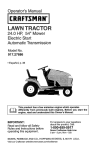
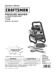
Operator's Manual
GARDEN
TRACTOR
26.0 HP,* 54" Mower
Electric Start
6 Speed Transaxle
Model No.
917.25025
• Espar_ol, p. 36
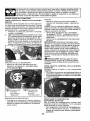
This product has a low emission engine which operates
1
differently from previously built engines. Before you start the
engine, read and understand this Operator's Manual.
IMPORTANT:
For answers
Read and follow all Safety
Rules and Instructions
before
operating this equipment.
about this product, Call:
to your questions
1-800-659-5917
Sears Craftsman
Help Line
5 am - 5 pro, Mon - Sat
Gasoline containing up to 10% ethanol (EIO} is acceptable for use in this machine,
The use of any gasoline exceeding 10% ethanol (EIO) will void the product warranty.
Esta m_quina puede utilizar gasolina con un contenido de basra el 10% de etanol (El0).
E1uso de una gasolina que supere el 10% de etanol (EIO) anular_ la garantia del produeto,
Sears Brands Management Corporation, Hoffman Estates, IL 60179 U.S.A.
Visit our Craftsman website:www.sears.comJcraftsman
*Asrated
bytheengine manufacturer
446651
Warranty ..................................................
2
Safety Rules ............................................
3
Product Specifications
.............................
6
Ass embly/P re-Operation
.........................
8
Operation ...............................................
13
Maintenance
Schedule ..........................
20
Maintenance ..........................................
20
Service and Adjustments ....................... 25
Storage ..................................................
30
Troubleshooting
.....................................
31
Sears Service .......................... Back Cover
Craftsman Riding Equipment Warranty
CRAFTSMAN FULL WARRANTY
FOR TWO YEARS from the date of purchase, all non-expendable
parts of this riding equipment are
warranted
against any defects in material or workmanship.
A defective non-expendable
part will
receive free in-home repair or replacement
if repair _s _mposs_ble.
FOR FIVE YEARS from the date of purchase, the frame and front axle of th_s riding equipment are
warranted
against any defects in matenal or workmanship.
A defective frame or front axle w_tl receive
free in-home repair or replacement
if repair _s _mposs_ble
FOR 90 DAYS from the date of purchase, the battery (an expendable
part) of this riding equipment
is warranted
against any defects in material or workmanship
(our testing proves that it will not hold a
charge). A defective battery w_ll receive free in-home replacement.
ADDITIONAL
LIFETIME
LIMITED
WARRANTY
on CAST
IRON
FRONT
AXLE
(if equipped)
FOR AS LONG AS tT IS USED by the original owner after the fifth year from the date of purchase, the
cast iron front axle (if equipped) of this riding equipment is warranted against any defects in material or
workmanship
With proof of purchase, a defective cast front axle will receive free in-home replacement.
WARRANTY
SERVICE
For warranty coverage
details to obtain
web site: www.craftsman.com
free repair or replacement,
call 1-800-659-5917
In all cases above, ff part repair or replacement
is impossible, the riding equipment
free of charge with the same or an equivalent
model.
All of the above warranty coverage
is void if this riding
commercial
services or if rented to another person.
This warranty
include:
•
covers
ONLY defects
Expendable
parts (except battery)
including but not limited to blades,
_n material
equipment
and workmanship,
is ever
or visit the
will be replaced
used while providing
Warranty
coverage
does
that can wear out from normal use within the warranty
spark plugs, air cleaners, belts, and oil filters.
NOT
period,
•
•
Standard maintenance
servicing, oil changes, or tune-ups.
T_re replacement
or repair caused by punctures
from outside objects,
such as nails, thorns,
stumps, or glass.
• Tire or wheel replacement
or repair resulting from normal wear, accident, or improper operation or
maintenance.
•
•
•
•
Repairs necessary
because
of operator abuse, including but not limited to damage caused by
towing objects beyond the capability of the riding equipment,
impacting
objects that bend the
frame, axle assembly
or crankshaft, or over-speeding
the engine.
Repairs necessary
because
of operator negligence,
including
but not limited to, electrical
and
mechanical
damage
caused by improper
storage, failure to usa the proper grade and amount
of engine oil, failure to keep the deck clear of flammable
debris, or failure to maintain the riding
equipment according to the instructions contained in the operator's manual.
Engine (fuel system) cleaning or repairs caused by fuel determined
to be contaminated
(stale). In general, fuel should be used within 30 days of its purchase date.
Normal deterioration
and wear of the exterior finishes, or product label replacement.
This warranty
state to state.
Sears
Brands
gives you specific
Management
legal
rights,
Corporation,
and you may also have other
Hoffman
Estates,
or oxidized
rights which vary from
IL 60179
_DANGER:
This cutting machine is capable of amputating
hands and feet and
throwing objects. Failure to observe the following
safety instructions
could result
in serious injury or death.
_WARNING:
In order to prevent accidental starting when setting up, transporting,
adjusting or making repairs, always disconnect spark plug wire and place wire where
it cannot contact spark plug.
•
Neverdirectdischarged
materialtoward
anyone.
Avoid discharging
material
against a wail or obstruction.
Material
may ricochet back toward the operator.
Stop the blades when crossing gravel
surfaces.
_D_WARNING:
Do not coast down a hill in
neutral, you may lose central of the tractor.
_t, WARNING:
Tow only the attachments
that are recommended
by and comply with
specifications
of the manufacturer
of your
tractor. Use common sense when towing.
Operate only at the lowest possible speed
when on a slope. Too heavy of a load, while
on a slope, is dangerous.
Tires can lose
traction with the ground and cause you to
lose control of your tractor.
•
•
•
_I_WARNING:
Engine exhaust, some of
its constituents, and certain vehicle components contain or emit chemicals known to
the State of California to cause cancer and
birth defects or other reproductive
harm.
_,WARNING:
Battery posts, terminals and
related accessories contain lead and lead
compounds, chemicals known to the State of
California to cause cancer and birth defects
or other reproductive
harm. Wash hands
after handling.
I. GENERAL
•
•
•
•
•
OPERATION
Read, understand, and foltow all instructions on the machine and in the manual
before starting.
Do not put hands or feet near rotating
parts or under the machine. Keep clear
of the discharge opening at all times.
Only allow responsible adults, who are
familiar with the instructions, to operate
the machine.
Clear the area of objects such as rocks,
toys, wire, etc., which could be picked
up and thrown by the blades.
Be sure the area is clear of bystanders
before operating. Stop machine ifanyone
enters the area.
Never carry passengers.
Do not mow in reverseun]ess
absolutely
necessary. Always look down and behind
before and while backing.
•
•
Do not operate machine without the entire grass catcher, discharge chute, or
other safety devices in place and working.
Slowdown
before turning.
Never leave a running machine unattended.
Always turn off blades, set
parking brake, stop engine, and remove
keys before dismounting.
Disengage
blades when not mowing.
Shut off engine and wait for all parts to
come to a complete stop before cleaning
the machine, removing the grass catcher,
or unclogging the discharge chute.
Operate machine only in daylight or good
artificial light.
Do not operate the machine while under
the influence of alcohol or drugs.
Watch for traffic when operating near or
crossing roadways.
Use extra care when loading or unloading
the machine into a trailer or truck.
Always wear eye protection when operating machine,
Data indicates that operators, age 60
years and above, are involved in a large
percentage of riding mower-related injuries. These operators should evaluate
their ability to operate the riding mower
safely enough to protect themselves and
others from serious injury.
Followthe manufacturer's
recommendation for wheel weights or counterweights.
Keep machine free of grass, leaves or
other debris build-up which can touch hot
exhaust/engine
parts and burn. Do not
allow the mower to plow leaves or other
debris which can cause build-up to occur. Clean any oil or fuel spillage before
operating or storing the machine. Af[ow
machine to cool before storage.
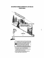
I!. SLOPE
OPERATION
Slopes are a major factor related to loss of
control and tip-over accidents, which can
result in severe injury or death. Operation
on all slopes requires extra caution. If you
cannot back upthe slope or if you feet uneasy
on it, do not mow it,
•
Mow up and down slopes, not across.
Watch for holes, ruts, bumps, rocks, or
other hidden objects.
Uneven terrain
could overturn the machine.
Tall grass
can hide obstacles.
•
•
•
Choose a low ground speed so that you
will not have to stop or shift while on the
slope.
D o not mow on wet grass. Tires may lose
traction,
Use extra care when approaching blind
corners, shrubs, trees, or other objects
that may block your view of a child.
Always keep the machine in gear when
going down slopes. Do not shiftto neutral
and coast downhill.
•
IV. TOWING
Avoid starting, stopping, or turning on a
slope, Ifthetires Iosetraction, disengage
the blades and proceed slowly straight
down the slope.
Keep all movement on the slopes slow
and gradual.
Do not make sudden
changes in speed or direction, which
could cause the machine to roll over.
Use extra care while operating machine
w_th grass catchers or other attachments;
they can affect the stability of the machine. Do no use on steep slopes.
Do not try to stabilize the machine by
putting your foot on the ground.
Do not mow near drop-offs,
ditches,
or embankments.
The machine could
suddenly roll over if a wheel is over the
edge or if the edge caves in.
•
Tow only with a machine that has a h_tch
designed for towing. Do not attach towed
equipment except at the hitch point.
Followthemanufacturer'srecommendation for wetght limits for towed equipment
and towing on slopes.
Never allow children or others in or on
towed equipment.
On slopes, the weight of the towed equipment may cause loss of traction and loss
of control.
Travel slowly and allow extra distance to
stop.
V, SERVICE
SAFE HANDLING
OF GASOLINE
To avoid personal injury or property damage, use extreme care in handling gasoline.
Gasoline is extremely flammable
and the
vapors are explosive.
•
Extinguish all cigarettes,
ctgars, pipes,
and other sources of ignttion.
Use only approved gasoline contatner.
• Never remove gas cap or add fuel with
the engtne running. Allow engine to cool
before refueling.
Never fuel the machine indoors.
Never store the machine or fuel container
where there is an open flame, spark, or
pilot light such as on a water heater or
other appliances.
Never fill containers inside a vehicle or
on a truck or trailer bed with plastic liner.
Always place containers on the ground
away from your vehicle when filling.
II!, CHILDREN
A(_WARNING:
CHILDREN CAN BE INJURED
BY THIS EQUIPMENT The American Academy of Pediatncs recommends
that children
be a minimum of 12 year of age before operating a pedestrian controlled fawn mower
and a minimum of 16 years of age before
operating a riding lawn mower.
Tragic accidents can occur if the operator
is not alert to the presence
of children.
Children are often attracted to the machine
and the mowtng activity.
that children wiil remain
saw them.
Keep children out of the mowing area
and in the watchful care of a responstble
adult other than the operator.
Be alert and turn machine off if a child
enters the area.
Before and while backing, look behind
and down for small children.
Never carry children, even with the blades
shut off. They may fall off and be seriously
injured or interfere with safe machine
operation. Children who have been given
rides in the past may suddenly appear in
the mowing area for another ride and be
run over or backed over by the machine.
Never allow children to operate the machine.
Never assume
where you last
4
• Remove
gas-powered
equipment
from •
thetruckortrailerandrefuel
it onthe
ground.
Ifthisisnotpossible,
thenrefuel
such
equipment
with
aportable
container,
rather
thanfroma gasoline
dispenser
nozzle.
Keep
thenozzle
incontact
withtherim •
ofthefueltankorcontainer
opening
at
alltimesuntil
fueling
iscomplete,
Donot
useanozzle
lock-open
device.
•
• Lffuelis
spilled
onclothing,
change
clothingimmediately.
°
• Never
overfill
fuettank.
Replace
gascap
andtighten
securely.
GENERAL
•
•
•
•
-
•
SERVICE
Never ope rate machine in a closed area.
Keep all nuts and bolts tightto be surethe
equipment is in safe working condition.
Maintain or replacesafetyand
instruction
tabe]s, as necessary.
Be sure the area is clear of bystanders
before operating. Stop machine ffanyone
enters the area.
Never carry passengers.
Do not mow in reverse unless absolutely
necessary. Always look down and behind
before and while backing.
Never carry children,
even with the
blades shut off. They may fail off and
be seriously injured or interfere with safe
machine operation. Children who have
been given rides in the past maysuddenly
appear in the mowing area for another
ride and be run over or backed over by
the machine.
Keep children out of the mowing area
and in the watchful care of a responsible
adult other than the operator.
•
•
•
•
•
•
•
Nevertamperwith safety devices. Check
their proper operation regularly.
Keep machine free of grass, leaves, or
other debris build-up. Clean oil or fuel
spillage and remove any fuel-soaked debris. Allow machine to cool before storing.
tf you strike a foreign object, stop and
inspectthe machine. Repair, if necessary,
before restarting.
Never make any adjustments or repairs
with the engine running.
Check grass catcher components andthe
discharge chute frequently and replace
with manufacturer's recommended parts,
when necessary.
Mower blades aresharp. Wrapthe blade
or wear gloves, and use extra caution
when servicing them,
Check brakeoperationfrequently. Adjust
and service as required.
Be alert and turn machine off if a child
enters the area.
Before and while backing, look behind
and down for small children.
Mow up and down slopes (15 + Max), not
across.
Choose a low ground speed so that you
will not have to stop or shift while on the
slope.
Avoid starting, stopping, orturning on a
slope, tfthetireslosetraction,
disengage
the blades and proceed stowly straight
down the slope.
If machine
stops white going uphill,
disengage blades, shift into reverse and
back down stowly.
Do notturn on slopes unless necessary,
and then, turn slowly and gradually
downhill, if possible.
Whenloading
or unloadingthis
machine,
do not exceed the maximum
recommended operation angle of 15 °.
PRODUCT
SPECIFICATIONS
Gasoline Capactty 4.0 Gallons/15,14 L
and type
Regular Unleaded
Oil Type.
(API. SG-SL)
SAE 10W30 [above 32°F/0_C
SAE 5W30 (be_ow32°F/0_C
Od Capacity
64 Oz./1,96 L
Spark Plug'
Champton RC12YC
(Gap..030"/0.76 ram)
Forward:
1st 1.0/1,6
2nd 1.4/2,3
3rd 2 1/3,4
4th 3 1/5,1
5th 4.0/6,4
61h 5.1/8.2
Reverse
0 - 1.6/2.6
Ground Speed
(MphiKph)
in the state of California the above is required
by law (Section 4442 of the California Public
Resources Code). Other states may have
simtlar laws. Federal laws apply on federal
lands. A spark arrestor for the muffler is
available through you r nearest Sears service
center (See REPAIR PARTS manual),
REPAIR PROTECTION
AGREEMENTS
Charging System.
15 Amps @ 3GODRPM
Congratulations
on making a smart purchase. Your new Craftsman@
product is
designed and manufactured
for years of
dependable operation, But like all products,
it may require repair from time to time. That's
when having a Repair Protection Agreement
can save you money and aggravation.
Battery.
Amp/Hr'
Min. CCA'
Case size:
Purchase a Repalr Protection Agreement
now and protect yourself from unexpected
hassle and expense.
Blade Bolt Torque:
45-55 Ft, Lbs/62-75
28
230
U1R
Nm
CONGRATULATIONS
on your purchase of
a new tractor. It has been designed, engineered and manufactured to gtve you the best
possible dependability
and performance.
S he uld you experience any problem you cannot eastly remedy, please contact a Sears or
other qualified service center. We have competent, well-trained representatives
and the
proper tools to service or repatr this tractor.
Please read and retain this manual.
The
instructions
will enable you to assemble
and maintain your tractor properly. Always
observe the "SAFETY RULES".
CUSTOMER
RESPONSIBILITIES
• Read and observe the safety rules.
• Follow a regular schedule in maintaining,
canng for and using your tractor.
• Follow instructions under"Maintenance"
and "Storage" sections of this manual.
• Wear proper Personal Protective Equipment (PPE) while operating this machine,
including (at a minimum) sturdy footwear,
eye protection, and hearing protection.
Do not mow in shorts and/or open toed
footwear.
• Aiways letsomeone
mowing.
knowyou
are outside
_kWARNING:
Thistractor is equipped with
an internal combustion engine and should not
be used on or near any unimproved forestcovered, brush-covered
or grass-covered
land unless the engine's exhaust system is
equipped with a spark arrester meetrng applicable local or state laws (if any). Ifaspark
arrester is used, tt should be maintained
in effective working order by the operator.
Here's what's included
in the Agreement:
Expert service byour 12,000 professional
repair specialists.
•
Unlimited service and no charge for parts
and labor on all covered repairs.
Product replacement
product can't be fixed.
•
if your
covered
Discount of 10% from regular price of
service and service-related
parts not
covered by the agreement; also, 10% off
regular price of preventive maintenance
check.
Fast help by phone - phone support
from a Sears representative on products
requiring in-home repair, plus convenient
repair scheduling.
Once you purchase the Agreement, a simple
phone call is all that it takes for you to schedu le service. You can call anytime day or night,
or schedule a service appointment online.
Sears has over 12,000 professional
repair
specialists,
who have access to over 4.5
million quaJity parts and accessories. That's
the kind of professionalism you can count on
to help prolong the life of your new purchase
for years to come. Purchase your Repair
Protection Agreement today!
Some limitations
and exclusions
apply.
For prices and additional information call
1-800-827-6655.
SEARS
INSTALLATION
SERVICE
For Sears professional installation of home
appliances,
garage door openers,
water
heaters, and other major home items, in the
U.S.A. call 1-800-4-MY-HOME®
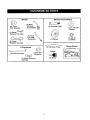
Mower Front Wheel
Mower
©
(2) Rear _
Lift Link
(5) 1-3/16
O.D. Washers
._
(1) Shoulder
BoR
(1) 1-1/40.D.
Assemblies
Washer
(1) Small
Retainer Springs
@
(1) Front
Lift Link
\_'_
(1) Wheel
Assembly
Retainer
(1)3!s-_6
Loci(nut
Springs
(1) Oil Drain Tube
if Equipped
(t) 3/40.D.
(1) Anti-Sway
Bar
(1) Small
Springs
Keys
Washers
Retainer
(2) Keys
Slope Sheet
Your new tractor has been assembled at the factory with exception of those parts left
unassembled for shipping purposes. To ensure safe and proper operation of your tractor
all parts and hardware you assemble must be tightened securely.
Use the correct tools
as necessary
TOOLS
to insure proper tightness.
REQUIRED
A socket wrench
easier. Standard
(2) 7/I6"
FOR ASSEMBLY
set will make assembly
wrench sizes are listed,
wrenches
Utility knife
(1) 1/2" wrench
Tire pressure
(1) 3/4" wrench
Pliers
(1) 3/4" socket w/drive
(1) 9/16" wrench
gauge
ratchet
CARTON
Remove all accessible loose parts and
parts cartons from carton,
Cut along dotted lines on all four panels
of carton. Remove end panels and lay
side panels flat.
Remove mower and packing materials.
Check for any additional loose parts or
cartons and remove,
BEFORE
REMOVING
FROM SKID
TO CHECK
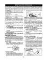
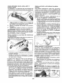
1.
SEAT
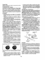
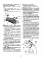
1. Sit in seat.
2. Lift up adjustment lever (A) and slide seat
until a comfortable position is reached
which allows you to press clutch/brake
pedal all the way down,
3. Release lever to lock seat in position,
Flashlig ht
When right or left hand is mentioned in this
manual, itmeans whenyou are intheoperating
position (seated behind the steering wheel).
TO
REMOVE
TRACTOR
FROM
CARTON
UNPACK
ADJUST
TRACTOR
BA'I-rERY
Lift hood to raised position.
NOTE: If this battery is put into service after
month and year indicated on label (label is
located between terminals) charge battery
for minimum of one hour at 6-10 amps. (See
"BATTERY" in Maintenance
section of this
manual for charging instructions),
Forbatteryand batterycableinstallationsee
"REPLACING BATTERY" inthe"Service
and Adjustments" sectio n in this manual.
NOTE: You may now roll your tractor offthe
s kid. Follow the instructions below to remove
the tractor from the skid.
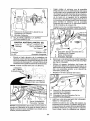
_:_ WARNING:
Before starting, read, understand and follow all instructions
in the
Operation section of this manual. Be sure
tractor is in a welFventilated
area. Be sure
the area in front of tractor is clear of other
people and objects.
TO ROLL
Operation
function
TRACTOR
section
of
OFF SKID
for location
(See
and
controls)
1. Raise attachment lift lever to _tshighest
position,
2. Release parking brake by depressing
clutch/brake
pedal.
3. Place gearshift lever in neutral position.
4. Roll tractor forward off skid.
Continue with the Instructions
TO INSTALL
MOWER
that follow,
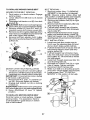
1. SET PARKING
BRAKE LEVER AND
LOWER ATTACHMENT LIFT LEVER
Depress clutch/brake
down and hold.
pedal all the way
Pull parking brake lever up and hold,
release pressurefrom clutch/brake pedal,
then release parking brake lever. Pedal
should remain in brake position. Ensure
parking brake will hold tractor secure.
\t
Brake
Lever
_IbCAUTION:
Lift lever is spring loaded.
Have a tight grip on lift lever, lower it slowly
and engage in lowest position,
Lift lever is
located on left side of fender.
3. TURN STEERING WHEEL
POSITION MOWER
•
Lift
Lever
Turn steering wheel to the left as far as it
witl go and position mower on right side of
tractorwith deflector shield (Q) to the right.
Front
2. ASSEMBLE
FRONT
(VV) TO FRONT
GAUGE
WHEEL
OF MOWER
Q.
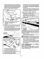
4. SLIDE MOWER
°
L
H.
W.
X.
Y.
Z.
LEFT AND
UNDER
Shield
TRACTOR
Bring belt forward and check belt for
proper routing in all mower pu!leygrooves.
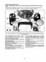
NOTE: Be sure mower side suspension
arms (A) are pointing forward before sliding
mower under tractor.
Front Mower Bracket
Front Gauge Wheel
Shoulder Bolt
1-1/40.D, Washer
3/8-16 Locknut
Side Suspension
Deflector
Slide mower under tractor
centered under tractor.
A.
Mower
B.
C,
D,
E.
F.
H.
Retainer Spdng
Rear Lift Link(S)
Right Side Rear Mower Bracket
Front Lift Link Assembly
Front Suspension
Bracket
Front Mower Bracket
Arms
t.
K.
L
M.
Q.
S.
W.
Left Side Rear Mower Bracket
Belt Tension Rod
Locking Bracket
Engine Clutch Pulley
Deflector Shield
Anti-Sway Bar
Front Gauge Wheel
until
it is
Pivottheintegrated
washer
endofantisway
bar(S)towards
mower
deck
bracket
onrightsideofmower.
Insert
integrated
washer
endofbarintoholeinrearmower
bracket
(D).Move
mower
asneeded
to
insert
integrated
washer
endofbarinto
rearmower
bracket
(D).
Secure
withsmallwasher
andsmall
retainer
spring
asshown.
A. Mower
Side
Suspens,on
Arms
Q. Def,ector Shie,d
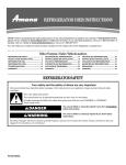
5. INSTALL ANTI-SWAY
_____
_4_
BAR (S)
_./" _Z!
(IF EQUIPPED)
I_::
I_'_
,
Towards
Transaxle
•
From right side of mower, first insert
90 ° end of anti-sway bar (S) into hole in
transaxle
bracket (T), located near left
rear tire in front of transaxle.
Anti-Sway
Bar(S)
Location _._
•
_
\
D. R_ghtSide Rear Mower Bracket
Bracket[iS.
_/
sD. Anti-Sway
Anti-sway
n,ght Side Bar
Rear M°wer
Bar
Transaxle Bracket
T. Transaxle Bracket
6. ATTACH MOWER SIDE SUSPENSION
ARMS (A) TO CHASSIS
Integrated Washer End I
NOTE: Flashlight
_
_
Towards "ll_/
Mower Deck _'_J
_1
I 90° End
_
Pos ition front hole in side s uspens ion arm
(A) over pin on outside of tractor chassis
and secure with large washer and large
retainer spring (B).
may be helpful•
._ .
" .......
,_-'-,:- ....
.:.' _ ;
_
Repeat on opposite
...,
side of tractor.
,
.. ,._,:.:..
,
Transaxie Bracket tq-)
Located Between Rear Tires
A. Mower Side Suspension Arms
B. Retainer Spring
D. R_ghtSide Rear Mower Bracket
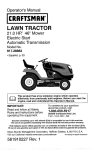
7. ATTACH
•
REAR LIFT LINKS (C)
Insert rod end of rear lift link (C) into hole
(U) in tractor lift shaft suspension arm
and pivot link down to mower.
Lift rear corn er of mower and position slot
in link assembly over pin on rear mower
bracket (D) and secure with largewasher
and large retainer spring.
NOTE: Depending on model, bracket (T) may
be different than shown but hole for anti-sway
bar will be in same position/location.
•
10
Repeat on opposite
side of tractor.
9
•
•
C, Rear Lift Link(s)
D. Right Side Rear Mower
'U. Hole
8
ATTACH
Bracket
FRONT LINK (E)
M.Engine
Clutch Pulley
Turn steering wheel to position wheels
straight forward,
From front of tractor, insert rod end of
front link (E) through front hole in tractor
front suspension
bracket (F).
Move to left side of mower and and insert
•
•
IMPORTANT: Check belt for proper routing
in alf mower pulley grooves and under
mandrel covers.
•
large retainer spring (G) through hole in
front link (E) behind ?ront suspension
bracket (F).
NOTE: Requires deck lifting.
/"
:_.
E
G.
H.
J.
M.
/
f
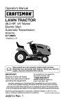
Engage belt tension rod (K) on locking
bracket (L).
_iLCAUTION-" Belt tension rod is spring
loaded. Have a tight grip on rod and engage
slowly.
• Raise attachment lift lever to highest
position.
If necessary, adjust gauge wheels
before operating mower as shown in the
Operation section of this manual.
Insert other end of link (E) into hole in
front mower bracket (H) and secure with
washer and small retainer spring (J).
Front Link
Location,
INSTALL BELT ON ENGINE CLUTCH
PULLEY (M)
Disengage belt tension rod (K) from
locking bracket (L).
Install bett onto engine clutch pulley (M).
, '\2;\
! , b e__z.%j
__/-__i__*._" ,.....
',
MOWER
DRIVE
BELT INSTALLATION
Follow
procedure
described
in "TO
REPLACE MOWER BLADE DRIVE BELT"
in the "Service and Adjustments"
section of
this manual.
Front Lift Unk Assembly
Front Suspension Bracket
Large Retainer Spring
Front Mower Bracket
Small Retainer Spring
Engine Clutch Pulley
11
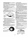
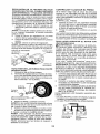
CHECK
TIRE
PRESSURE
t_CHECKLIST
The tires on your tractor were over-inflated
at the factory for shipping purposes. Co rrect
tire pressure is tmportant for best cutting
performance.
• Reducetire pressureto PSI shown ontires.
Before you operate your new tractor, we
wish to assure that you receive the best
performance
and satisfaction
from this
Quality Product.
CHECK
DECK
Please review the following
For best
should be
MOWER"
section of
cutting results, mower housing
properlyleve[ed,
See "TO LEVEL
in the Service and Adjustments
this manual.
CHECK
FOR
ALL BELTS
LEVELNESS
PROPER
POSITION
OF
See the figures that are shown for replacing
motion and mower blade drive belts in the
Service and Adjustments section of this manual. Verify that the belts are routed correctly.
CHECK
BRAKE
checklist:
All assembly
instructions
have been
completed.
No remaining loose parts in carton.
q/" Battery
is properly
prepared
and
charged.
J Seat is adjusted comfortably
and tightened securely.
J All tires are properly inflated. (For shipping p urposes, the tires were overinflated
at the factory).
J" Be sure mower deck is properly leveled
stde-to-side/frent-to-rear
for best cutting
results. (Tires must be properly inflated
for leveling).
1/" Check mower and drive belts, Be sure
SYSTEM
After you learn how to operate your tractor,
check to see that the brake is operating properly, See"TO CH EC K BRAKE" in the Service
and Adjustments
sectton of th_s manual.
they are routed properly around pulleys
and inside afl belt keepers.
_" Check wiring. See that all connections
are still secure and wires are properly
clamped.
Wh_le learning howto useyour tractor, pay extra attention to the following im portant items:
Engine oil is at proper level.
Fueltankis filled with fresh, clean, regular
unleaded gasoline.
J" Become familiar with all controls, their
location and function.
Operate them
before you star the engine.
Be sure brake system is in safe operating
condition.
Be sure Operator Presence System and
Reverse Operation System (ROS) are
working properly (See the 0 peration and
Maintenance sections in this manual).
12
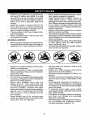
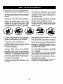
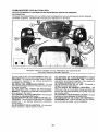
These
symbols
mayappear
onyourtractor
orinliterature
supplied
withtheproduct.
Learn
andunderstand
theirmeaning.
R
REVERSE
N
H
NEUTRAL
HIGH
8
OFF
UGHTS
ON
®
REVERSE
OPERATION
SYSTEM
(ROS)
FUEL
A'Fi'ACHMENT
CLUTCH DISENGAGED
CHOKE
FAST
SLOW
IGNITION
I,el,I
ENGINE
I ,I
L
LOW
ENGINE
BA3-rERY
ON
ENGINE
REVERSE
ATTACHMENT
CLUTCH
ENGAGED
B
(®)
START
PARKING
FORWARD
DANGER,
KEEP HANGS
AND FEET AWAY
BRAKE
CRUISE
KEEP
SWITCH
MOWER
CO N'IrROL
AREA
CLEAR
[SEE
SAF_F_
MOWER
HEIGHT
LIFT
CLUTCPJBRAKE
PEDAL
SLOPE
RULES
HAZARDS
SEC33ON)
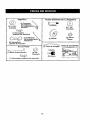
DANGER
which,
will
result ind=cates
in death aorhazard
serious
injury.if not avoided,
WARNING
hazard
which,
If not avoided,
could resultindicates
in deatha or
serious
injury.
FREE WH EEL
(At.'tornatlc
Models
only)
CAUTION
indicates
which, if
not avoided,
might result
in minora hazard
or moderate
injury.
CAUTION when used without the alert symbol,
Indicates a situation that could result in damage
to the tractor and/or engine.
Failure to follow instructions
could result in serious injury or
death. The safety alert symbol
is used to identify safety information about hazards which can
result in death, serious injury
and/or property damage.
HOT SURFACES indicates a hazard which,
,r_,.,'_
_, if not ave dad could result in death, set ous injury
and/or property damage.
._,
FIRE =ndlcates
hazard serious
which, Ifinjury
mot avoided,
could
result inadeath,
and/or
property damage.
13
KNOWYOURTRACTOR
READ
THISMANUAL
ANDSAFETY
RULES
BEFORE
OPERATING
YOUR
TRACTOR
Compare the illustrations with your tractor to familiarize yourself with the locations of
various controls and adjustments. Save this manual for future reference.
03065
Our tractors
conformto
the applicable safety standards
dards Institute.
(A) ATFACHMENT
LIFT LEVER - Used to
raise and lower the mower or other attach-
of the AmedcanNationaIStan-
(G) REVERSE
OPERATION
SYSTEM
(ROS) "ON" POSITION - Allows operation
of mower or other powered attachment while
in reverse.
(H) LIGHT SWITCH - Turns the headhghts
on and off.
ments mounted to your tractor.
(B) CLUTCH/BRAKE
PEDAL - Used for
declutching
and braking the tractor and
starting the engine.
(C) PARKING BRAKE - Locks clutch/brake
pedal into the brake position.
(D) THROTTLE CONTROLUsed to control
engine speed.
(E) ATTACHMENT
CLUTCH SWITCH Used to engage the mower blades, or other
attachments
mounted to your tractor.
(F) IGNITION SWITCH - Used for starting
and stopping the eng=ne.
(J) GEARSHIFT LEVER - Selects the speed
and direction of the tractor,
(N) CHOKE CONTROL- Usedwhenstarting
a cold engine.
(P) SERVICE REMINDER / HOUR METER
- Indicates when service is required for the
engine and mower.
14
Theoperation
ofanytractorcan
result in foreign objects thrown intothe
eyes, which can result in severe eye damage. Always wear safety glasses
or eye shields while operating your tractor or performing any adjustments
or repairs. We recommend standard safety glasses or a wide vision safety
mask worn over spectacles.
HOW
TO USE YOUR
TO SET PARKING
TRACTOR
BRAKE
Your tractor is equipped with an operator
presence sensing switch. When engine is
running, any attempt bythe operator to leave
the seat without_irst setting the parking brake
will shut off the engine.
1, Depress clutch/brake
pedal (B) all the
way down and hold.
2. Pull parking brake lever (C) up and hold,
release pressure from brake pedal (B),
then release parking brake lever. Pedal
should remain in brake position. Make
sure parking brakewill holdtractorsecure.
NOTE: Failureto movethrottlecontrot
between
half and full speed (fast)position,
before
stopping, may cause engine to "backfire".
• Turn ignition key (F) to "STOP" position
and remove key. Always remove key when
leaving tractorto prevent unauthorized use.
• Never use choke (N) to stop engine.
IMPORTANT:
Leaving the ignition switch in
any position other than "STOP" will cause
the battery to discharge and go dead.
NOTE: U rider certain conditions when tractor
is standing idle with the engine running, hot
engine exhaust gases may cause "browning" of grass. To eliminate this possibility,
always stop engine when stopping tractor
on grass areas.
CAUTION:
Always stop tractor completely, as described above, and set parking
brake before leaving the operator's position.
TO USE THRO'FrLE CONTROL (D)
Always operate engine at full speed (fast).
, Operating engine at less than full speed
(fast) reduces engine's
operating
efficiency.
• Full speed (fast) offers the best mower
performance.
STOPPING
MOWER
BLADES
-
• To stop mower blades, move attachment
crutch clutch lever to "DISENGAGED"
position (_).
TO USE CHOKE CONTROL
(r_)
Attachment
Clutch Switch
"Engaged
GROUND
....
(rl"_)Attachment
Clutch Switch
Dtsengaged"
DRIVE -
• To stop ground drive, depress clutch/brake
pedal all the way down.
• Move gear shift
lever (J) to neutral
position.
ENGINE
•
(N)
Use choke control whenever you are starting
a cold engine. Do not use to start a warm
engine.
• To engage choke control, pull knob out.
SlowJy push knob in to disengage.
-
Movethrottle control (D) between half and
full speed (fast) position.
15
TO MOVE FORWARD
AND BACKWARD
The direction and speed of movement
controlled by the gearshift lever (J).
TO ADJUST
is
GAUGE WHEELS
Gauge wheels are properly adjusted when
they are slightly off the ground when mower
is at the desired cutting height in operating
position. Gauge wheels then keep the deck
in proper position to help prevent scalping
in most terrain conditions.
NOTE: Adjust gauge wheels with tractor on
a flat level surface.
I,
2.
3.
1. Adjust mower to desired cutting height
(See "TO ADJUST MOWER CUTTING
HEIGHT" in this section of manual),
2. With mower in desired height of cut position, gauge wheels should be assembled
so they are slightly off the ground. Install
gauge wheel in appropriate hole. Tighten
securely.
3. Repeat for all, installing gauge wheel in
same adjustment hole.
Start tractor with clutch/brake
pedal
depressed and gearshift lever in neutral
position.
Move gearshift lever to desired position.
S!owly release clutch/brake pedal to start
movement.
IMPORTANT:
beforeshlfting
so willsherten
Bringtractor to a complete stop
or changing gears. Failureto do
the usefulhfe of yourtransaxle.
o
TO ADJUST MOWER CUTTING HEIGHT
The position of the attachment lift lever (A)
determines the cutting height.
TO OPERATE
MOWER
Your tractor is equipped with an operator
presence sensing switch. Any attempt by the
operator to leave the seat with the engine
running and the attachment clutch engaged
will shut off the engine. You must remain
fully and centrally pos=tioned in the seat to
prevent the engine from hesitating or cutting
off when operating your equip ment on rough,
rolling terrain or hills.
1. Select desired height ol _cut with attachment lift lever.
• Put attachment lift lever in desired cutting
height slot.
• Slide pointer tab (T) to desired cutting
height as a reminder for next t=me you
2. Start mower blades by engaging
ment clutch control.
TO STOP MOWER BLADES
mow,
The cutting height range is approximately
1 to 4". The heights are measured from the
ground to the blade tip with the engine not
running. These heights are approximate
and may vary depending upon soil conditions, height of grass and types of grass
being mowed.
• The average lawn should be cut to approximately
2-1/2" during the cool season and to over 3" during hot months.
For healthier and better looking lawns,
mow often and after moderate growth.
• For best cutting performance, grass over
6" in height should be mowed twice. Make
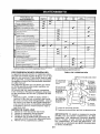
the f_rst cut relatwely high; the second to
desired height.
Disengage
attachment
attach-
clutch control.
_CAUTION:
Do not operate the mower
without either the entire grass catcher, on
mowers so equipped, orthe deflector shield
(S) in place.
16
REVERSE
OPERATION
SYSTEM
(ROS)
Your tractor is equipped with a Reverse
Operation System (ROS). Any attempt by
the operator to travel in the reverse direction
with the attachment crutch engaged will shut
off the engine unless ignition key is placed
in the ROS "ON" position.
_WARNING:
Backing up with the attachment clutch engaged white mowing is
strongly discouraged. Turningthe ROS "ON",
to allow reverse operation with the attachment clutch engaged, should only be done
when the ope rater decides it is necessary to
reposition the machine with the attachment
engaged. Do not mow in reverse unless
absolutely necessary.
USING THE REVERSE
SYSTEM -
OPERATION
On[y use if you are certain no children or other
bystanders will enter the mowing area.
1. Depress clutch/brake pedal all the way
down and hold.
2. With engine running, turn ignition key
counterclockwise
to ROS "ON" position.
3. Look down and behind before backing.
4. Move gear shift leverto reverse position
and slowly release clutch/brake pedal to
start movement.
5. When use of the ROS is no longer needed,
turn the ignition key clockwise to engine
"ON" position.
ROS "ON" Position
TO OPERATE
Engine "ON" Position
(Normal OpeTating)
TO TRANSPORT
• Raise attachment lift lever to its highest
position.
• When pushing or towing your tractor, be
sure gearshift lever is in neutral position.
• Do not push or tow tractor at more than
five (5) MPH.
NOTE: To protect hood from damage when
transporting your tractor on atruck or atrailer,
be sure hood is closed and secu red totractor.
Use an appropriate means of tying hood to
tractor (rope, cord, etc.).
TOWING CARTS AND OTHER ATtACHMENTS
Tow only the attachments that are recommended by and comply with specifications
of the manufacturer of your tractor. Use
common sense when towing. Too heavy of
a load, while on a slope, is dangerous. Tires
can lose traction with the ground and cause
you to lose control of your tractor,
SERVICE REMINDER/HOUR
METER
Service reminder shows the total number
of hours the engine has run and flashes to
indicate that the engine or mower needs servicing. When service is required, the service
reminder will flash for two hours. To service
engine and mower, see the Maintenance
section of this manual.
NOTE: Service reminder runs when the ignition key is in any position but "STOP". For
acurate reading, be sure key remains in the
"STOP" position when engine is not run ning.
BEFORE STARTING THE ENGINE
CHECK ENGINE OIL LEVEL
The engine inyour tractor has been ship pad,
from the factory, already filled with summer
weight oil.
1. Check engine oil with tractor on level
ground.
2. Unthread and remove oil fill cap/dipstick;
wipe oil off. Reinsert the dipstick into the
tube and rest oil fill cap on the tube. Do
notthread the cap onto the tube. Remove
and read oil level. If necessary, add oil
until "FULl" mark on dipstick is reached.
Do not overfill.
• For cold weather operation you should
change oil for easier starting (See the el[
viscosity chart in the Maintenance section
of this manual).
• Tochange engine oil,see the Maintenance
section in this manual.
ON HILLS
_,WARNING:
Do not drive up or down hills
with slopes greater than 15° and do not drive
across any slop e. Use the slope guide at the
back of this manual.
• Choosetheslewestspeed
beforestarting
up or down hills.
• Avoid stopping or changing speed on hills.
• If stopping is absolutely necessary, push
clutch/brake pedal quickly to brake position
and engage parking brake.
• Move gearshift lever to 1st gear. Be sure
you have allowed room for tractor to roll
slightly as you restart movement.
• To restart movement, slowly release parking brake and clutch/brake pedal.
• Make alf turns slowly.
17
ADD GASOLINE
• Fill fuel tank to bottom of filler neck, Do
not overfill.
Use fresh, clean, regular
unleaded
gasoline with a minimum
of
87 octane.
(Use of leaded gasoline will
increase carbon and lead oxide deposits
and reduce valve life). Do not mix oJIwith
gasoline, Purchase fuel in quantities that
can be used within 30 days to assure fuel
freshness.
,&CAUTION"
Wipe off any spilled oil or fuel,
Do not store, spill or use gasoline near an
open flame.
IMPORTANT:
When operating
in temperatures below 32 ° F(0°C), use fresh, clean
winter grade gasoline to help ensure good
cold weather starting.
TO START
1. Siton seat in operating position, depress
clutch/brake pedal and set parking brake.
2. Place gear shift lever in neutral position.
3.
Move attachment clutch to disengaged
position.
4. Move throttle control to fast position
5. Pull choke controlout for a cold enginestart
attempt. For a warm engine start attempt
the choke control may not be needed.
NOTE: Before starting, read the warm and
cold starting procedures below.
6. Insert key Into ignition and turn key
clockwise to start position and release
key as soon as engine starts. Do not run
starter continuously for morethan fifteen
seconds per minute. If the engine does
not start after several attempts, push
choke control in, wait a few minutes and
try again. If engine still does not start, putl
the choke control out and retry.
CAUTION:
Alcohol blended fuels (called
gasohol or using ethanol or methanol) can
attract moisture which leads to separation
and formation of acids during storage. Acidic
gas can damage the fuel system of an engine
while in storage. To avoid engine problems,
the fuel system should be emptied before
storage of 30 days or longer. Drain the gas
tank, start the engine and let it run until the
fuel lines and carburetorare empty. Usefresh
fuel next season, See Storage Instructions
for additional information. Never use engine
or carburetor cleaner prod ucts in the fuel tank
or permanent damage may occur.
RESERVE
ENGINE
When starting the engme for the first time or
if the engme has run out of fuel, it will take
extra cranking time to move fuel from the
tank to the engine.
WARM WEATHER
and above)
STARTING
(50°F/10°C
7. When engine starts, slowly push choke
control in until the engine begins to run
smoothly,
If the engine starts to run
roughly, pull the choke co ntrof out slightly
for a few seconds and then continue to
push the control in slowly.
FUEL VALVE OPERATION
f, Raise seat to access reserve fuel valve,
2. In normal operation, valve should be set
to primary (as shown in view)
3. If tractor runs out of fuel, rotate valve
handle to reserve.
4. Drive tractor to be refueled.
5. After refueling, return valve to primary
position,
• The attachments
and ground drive can
now be used, If the engine does not accept
the load, restart the engine and allow it to
warm up for one minute using the choke
as described above.
COLD WEATHER
and below)
STARTING
(50°F/10°C
7. When engine starts, slowly push choke
control in until the engine begins to run
smoothly. Continue to push the choke
control in small steps a_lowing the engine
to accept small changes in speed and
load, until the choke control is fully in.
If the engine starts to run roughly, pull
the choke control out slightly for a few
seconds and then continue to push the
control in slowly. This may require an
engine warm-up
penod from several
seconds to several minutes, depending
on the temperature.
• The attachments can be used during the
engine warm-up period and may require
the choke control be pulled out slightly.
Reserve
Fuel Valve
@
18
NOTE: If at a high altitude (above 3000 feet)
or in cold temperatures
(below 32°F/0°C)
the carburetor fuel mixture may need to be
adjusted for best engine performance.
See
"TO ADJ U ST CARBU RETQ R" in the Service
and Adjustments
section
of this manual.
MOWING
TIPS
• Tire chains cannot be used when the
mower housing is attached to tractor,
• Mowershould
beproperlyleveledforbest
mowing performance.
See "TO LEVEL
MOWER HOUSING" in the Service and
Adjustments section of this manual.
• The left hand side of mower should be
used for trimming.
• Drive so that clippings
are discharged
onto the area that has aiready been cut.
Have the cut area to the right of the tractor,
This will result in a more even distribution
of clippings and more uniform cutting,
• When mowing large areas, start byturning
to the rig ht so that clippings will discharge
away from shrubs, fences, driveways,
etc. After one or two rounds, mew in the
opposite direction making left hand turns
until finished.
• If grass is extremely tall, it should be
mowed twice to reduce toad and possible
fire hazard from dried clippings,
Make
first cut relatively high; the second to the
desired height.
* Do not mow grass when it is wet. Wet
grass will plug mower and leave undesirable clumps.
Allow grass to dry before
mowing.
• Always operate engine at full throttle
when mowing
to assure better mowing performance
and proper discharge
of material.
ReguMte ground speed by
selecting a low enough speed to give the
mower cutting performance as well as the
quality of cut desired.
. When operating
attachments,
select a
ground speed that wi!l suit the terrain and
give best performance
of the attachment
being used.
19
MAINTENANCE
SEVERE
SCHEDULE
EVERY
eACH
USE
EVERY
e
E'_q_RY
25
HOURS
EVERY
50
HOURS
EVEry
loo
HOURS
BEFORE
S_SON SrO.AGE
HOURS
ii HII
Ch_ck
8rake
ChBck
Tt,r.e, Pressure
Check
Operator
A
Check
for Loose
C
ChecWReplec_
T
T
Lubncahor',
0
Chuck
R ,clean
Operation
Pres_nc_
If
.....
_
Blades
...
V F
.
........
Battery
V*=
V*
and
Debr=s
Check
TransaxJe
Check
Mower
Check
V-Belts
Check
Enqrne
Terminals
I_
If
Or{ Steering
....
"......
CooJlng
If
iV _
ii
i
Otl Level
If
E.ng=ne Oii Iwlth
Eng'ne
U
Clean
A_r Filter
G
Clean
Atr Screen
O'1 {w't_'°ut
ml biter)
(_1'I,_:
°'l f'lter)
V
V,.=
_=
V'2
Arrestor
If
U ReplaceOil F4ter (If equipped)
I_=
E cl_.. En_,.eoooE,
n_r,.$
V' =
Rep_.ce
Replace
GENERAL
Spark
P_U 9
A=r FIJI_K Paper
Fuel
V
Cartridge
_##'_
F;Iter
....
1.
2.
3.
4.
If
RECOMMENDATIONS
LUBRICATION CHART
The warranty on this tractor does not cover
items that have been subjected to operator
abuse or negligence. To receive full value
from the warranty, operator must maintain
tractor as instructed in this manual.
Some adjustments will need to be made periodically to properly maintain your tractor.
At least once a season, check to see If
you should make any of the adjustments
described
in the Service and Adjustments
section of this manual•
• At least once a year you should replace
the spark plug, clean or replace air ftlter,
and check blades and belts for wear. A
new spark plug and clean air filter assure
proper atr-fue] mixture and help your engine run better and last longer.
BEFORE
HHH n
V _
.......
MuffledSpark
Replace
If
Piate
Levelness
Change
5.
I_'
.
Level
Ctean
Inspect
V
V r
Chart
E
|
Systems
Fasteners
Mower
Battery
Chanq'e
& ROe
V
EACH
USE
Check engine oil level
Check brake operation.
ChecktJre pressure•
Check operator presence and
ROS systems for proper operation.
Check for loose fasteners.
_Steering
_ Spindle __r_
Sp{ndIe
Zerk __
_Front
Wheel I- _1
Bearing
Zerk
OSteering
Sector
_
_._;_
Zerk
"f_,. --_f_'-
OFrontWheel
._ _______, 7=-_.,,Beanng
,4_
_
Zerk
L_--_.@engine
"_
q
[-- _k._,_,"
_-7 f.L__._.
_
-@)Mandrel
Gear
II
L-=---_-_II
Teeth
J I
[_'_
[._._ _
OGeneral
@Referto
Pivot Bolts
_
_
Zerks
_
_(2)PivBts
Purpose Grease
Maintenance"ENGINE"Section.
IMPORTANT: Do not oil or grease the pivot
points which have special nylon bearings.
Viscous lubricants wilt attract dust and dirt
that will shorten the life of the self-lubricating
bearings. Ifyou feel they must be lubricated,
use only a dry, powdered graphite type lubricant sparingly.
2O
TRACTOR
CHECK REVERSE
SYSTEM
Always observe safety rules when performing
any maintenance,
BRAKE OPERATION
• Maintain proper air pressure in all tires
(See PSI on tires),
• Keep tires free of gasoline, oil, or insect
control chemicals
which can harm rubber.
• Avoid stumps, stones, deep ruts, sharp
objects and other hazards that may cause
tire damage.
NOTE: To seal tire punctures and prevent
flat tires due to slow leaks, tire sealant may
be purchased from your local parts dealer.
Tire sealant also prevents tire dry rot and
corrosion.
OPERATOR
PRESENCE
SYSTEM AND
REVERSE OPERATION SYSTEM (ROS)
BLADE CARE
For best results mower blades must besharp.
Replace worn, bent or damaged blades.
A CAUTION:
Use only a replacement
blade approved by the manufacturer of your
tractor. Using a blade not approved by the
manufacturer of your tractor is hazardous,
could damage your tractor and void your
warranty.
BLADE REMOVAL
1. Raise mowerto highest position to allow
access to blades,
NOTE: Protect your hands with gloves and/
or wrap blade with heavy cloth.
2. Remove blade bolt by turning counterclockwise.
3. Install newbladewithstamped"THIS
SIDE
UP" facing deck and mandrel assembly.
IMPORTANT;
To ensure proper assembly,
center hole in blade must align with star on
mandrel assembly,
4. Install and tighten blade belt securely
(45-55 Ft, Lbs./62-75 Nm torque).
IMPORTANT:
Special blade bolt is heat
treated,
Be sure operator
presence
and reverse
operation systems are working properly. If
your tractor does not function as described,
repair the problem immediately.
• The engine should not start unless the
brake pedal is fu[ly depressed, and the
attachment clutch control is in the disengaged position.
OPERATOR
PRESENCE
• When the engine is running,
by the operator to leave the
first setting the parking brake
off the engine.
• When the engine is running
tachment clutch is engaged,
by the operator to leave the
shut off the engine.
• The attachment clutch should
ate unless the operator is in
ROS "ON" Posit_on
(ROS)
• When the engine is running with the ignition
switch in the engine "ON" position and the
attachment clutch engaged, any attempt
by the operator to shift into reverse should
shut off the engine.
• Whenthe engine is running with the ignition
switch in the ROS "ON" position and the
attachment clutch engaged, any attempt
by the operator to s hiff into reverse should
NOT shut off the engine,
If tractor requires more than five (5) feet to
stop at highest speed in highest gear on a
level, dry concrete or paved surface, then
brake must be serviced. (See "TO CHECK
BRAKE" in the Service and Adjustments
section of this manual).
TIRES
CHECK
SYSTEM
OPERATION
any attempt
seat without
should shut
and the atany attempt
seat should
-Star
Assemb3y
BATTERY
Your tractor has a battery charging system
which is sufficientfor normal use. However,
periodic charging of the battery with an automotive charger will extend its life.
• Keep battery and terminals clean.
• Keep battery bolts tight.
• Keep small vent holes open.
* Recharge at 6-10 amperes for 1 hour.
NOTE: The original equipment battery on
your tractor is maintenance free. Do not
attempt to open or remove caps or covers.
Adding or checking level of electrolyte is
not necessary.
never operthe seat.
Engine "ON" Position
(Normal Operating)
21
TO CLEAN
BATTERY
AND TERMINALS
TO CHANGE
TRANSAXLE
ENGINE
OIL
Determine
temperature
range expected
before oil change,
All oil must meet API
service classification SG-SL.
• Be sure tractor is on level surface.
• Oil will drain more freely when warm.
• Catch oil in a suitable container.
!. Remove oil fill cap/dipstick.
Be careful
not to allow dirt to enter the engine when
changing oil.
2. Remove yellow cap from end of drain
valve and install the drain tube onto the
fitting.
3. Unlock drain valve by pushing inward
slightly and turning counterclockwise.
Oil Drain Valve
Corrosion and dirt on the battery and terminals can cause the battery to "leak" power.
1, Remove terminal guard.
2. Disconnect
BLACK battery cable first
then RED battery cable and remove
battery from tractor.
3. Rinsethe battery with plain waterand dry.
4. Clean terminals and battery cable ends
with wire brush until bright.
5. Coat terminals with grease or petroleum
jelly.
6, Reinstall
battery
(See "REPLACING
BATTERY"
in the SERVICE AND ADJUSTMENTS
section of this manual).
MAINTENANCE
Keep transaxle free from build-up of dirt and
chaff which can restrict cooling,
Do not attempt to clean transaxle
while
engine is running or while the transaxle is
hot. To prevent possible damage to seals,
do not use high pressure water or steam to
clean transaxle.
Locked
Yellow Cap_
To open, pull out on the drain valve.
Afferoi] has drained completely, close and
lock the drain valve by pushing inward
and turning clockwise until the pin is in
the locked position as shown.
6. Remove the drain tube and replace the
cap onto the end of the drain valve.
7. Refillengine with oilthrough oil filldipstJck
tube. Pour slowly. Do not overfill.
For
approximate
capacity see "PRODUCT
SPECI FI CATIONS" section ofthis manual.
8. Use gauge on oil fltl cap/dipstick
for
checking level. Insert dipstick into the
tube and rest the oil fill cap on the tube,
Do not thread the cap onto the tube when
taking reading. Keep oil at "FULL' line
on dipstick. Tighten cap onto the tube
securely when finished.
ENGINE OIL FILTER
LUBRICATION
Only use high quality detergent oil rated with
API service classification SG-SL. Sefectthe
oil's SAE viscosity grade according to your
expected operating temperature.
V_SCOSITY
Drain
4.
5.
ENGINE
SA_
|
Position_Tube
V-BELTS
Check V-belts for deterioration and wear after
100 hours of operation and replace if necessary. The belts are not adjustable. Replace
belts if they begin to slip from wear.
E
_ __
G_qAD_:S
Change the oil after every 50 hours of operation or at least once a year if the tractor is
not used for 50 hours in one year.
Check the crankcase oil tevel before starting
the engine and after each eight (8) hours of
operation.
Replace the engine oil filter every season or
every other oil change if the tractor is used
more than 100 hours in one year.
22
CLEAN AIR INTAKE/COOLING AREAS
Toensure propercooling,make surethegrass
screen, cooling fins, and other external surfaces ofthe engine are kept clean at alltimes.
Every 100 hours of operation (more often
under extremely dusty, dirty conditions),
remove the blower housing and other cooling
shrouds. Clean the cooling fins and external
surfaces as necessary. Makesurethecooling
shrouds are reinstalled.
AIR FILTER
Your engine wifl not run properly using a
dirty air filter. Service paper cartridge every
two months or every 25 hours of operation,
whichever occurs first.
Service paper cartridge more often under
dusty conditions.
Replace the paper cartridge annually, or after
every 100 hours of operation.
TO SERVICE
CARTRIDGE
NOTE: Operating the engine with a blocked
grass screen, dirty or plugged cooling fins,
and/or cooling shrouds removed will cause
engine damage due to overheating.
• Replace a dirty, bent, or damaged cartridge. Handle new cartridge carefully; do
not use if the rubber seal is damaged.
NOTE:
Do not wash the paper cartridge
or use pressurized air, as this will damage
the cartridge.
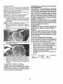
1. Open door (A) on the blower housing to
access the air cleaner element (B).
2. Unhook the latch (C) and remove the
element.
3. Gently tap the paper element to dislodge
dirt.
MUFFLER
Inspect and replace corroded muffler and
spark arrester (if equipped) as it could create
a fire hazard and/or damage.
SPARK PLUG(S)
Replace spark plug(s) at the beginning of
each mowing season or after every 100
hours of operation, whichever occurs first.
Spark plug type and gap setting are shown
in "PRODUCT SPECIFICATIONS" section
of this manual
IN-LINE FUEL FILTER
The fuel filtershould be replaced once each
season, if fuel filter becomes clogged, obstructing fuel flow to carburetor, replacement
is required.
1. With engine cool, remove filter and plug
fuel line sections.
2. Place new fuel filter in position in fuel line
with arrow pointing towards carburetor.
3. Be sure there are no fuel line leaks and
clamps are properly positioned.
4. Immediatelywipe up anyspilled gasoline.
4. Clean all air cleaner components of any
accumulated
dirt or foreign material.
5.
6.
Ctarn_amp
Prevent any dirt from entering the throat
of carburetor.
Install cieaned or new element on the
base and secure with latch.
Close and latch the door.
GLEAN
Fuel Filter
AIR SCREEN
Air screen must be kept free of dirt and chaff
to prevent engine damage from overheating.
Clean with a wire brush or compressed air to
remove dirt and stubborn dried gum fibers.
23
CLEANING
4.
Clean engine, battery, seat, finish, etc.
of all foreign matter.
Clean debris from steering plate.
Debris can restrict clutch/brake pedal
shaft movement, causing belt slip and
loss of drive.
•
Pull back the lock collar of the nozzle
adapter and push the adapter onto the
deck washout port at the left end of the
mower deck. Release the lock collar to
lock the adapter on the nozzle.
_il
JHose
_).,d_"_
Nozzle
_, CAUTION: Avoid all pinch points and
movable parts
Adapter_
Washout Port
Clutch/brake pedal
it
Clean
top side
II jl
Steering
IMPORTANT:
tion is secure.
Steering System, Dash,
Fender and Mower Not Shown
•
5.
Turn the water on.
Pinch
Points
6.
While sitting in the operator's position
on the tractor, re-start the engine and
place the throttle lever in the Fast ",t_"
position.
IMPORTANT:
Recheck the area making
certain the area is clear.
7.
Move the tractor's attachment clutch
control to the "ENGAGED"
position.
Remain in the operator's
position
with the cutting deck engaged until the
deck is cfeaned.
We do not recommend using a garden hose
or pressure washer to clean your tractor
unless the engine and transmission
are
covered to keep water out. Water in engine
or transmission
will shorten the useful life of
your tractor. Use compressed air or a leaf
blower to remove grass, leaves and trash
from tractor and mower.
8.
Move the tractor's attachment clutch
control to the "DISENGAGED"
position. Turn the ignition key to the STOP
position to turn the tractor's engine off.
Turn the water off.
9.
Pufl back the lock collar of the nozzle
adapter to disconnect the adapter from
the nozzle washout port.
10.
Move the tractor to a dry area, preferably a concrete or paved area. Place
the attachment
clutch control in the
"ENGAGED" position to remove excess
water and to help dry before putting the
tractor away.
PORT
Your tractor's
deck is equipped
with a
washout port on its surface as part of its
deck wash system. It should be utilized after each use.
1.
Dnve the tractor to a level, clear spot
on your lawn, near enough to a water
spigot for your garden hose to reach.
IMPORTANT:
Make certain the tractor's
discharge chute is directed AWAY from your
house, garage, parked cars, etc. Remove
bagger chute or mulch cover if attached.
2.
Make s ure the attachment clutch control
is in the "DISENGAGED"
position, set
the parking brake, and stop the engine.
3.
connec-
CAUTION:
Keep finished surfaces and wheels
free of all gasoline, oil, etc.
Protect painted surfaces with automotive type wax.
DECK WASHOUT
Tug hose ensuring
_kWAR NING: A broken or missing washout
fitting could expose you or others to thrown
objects from contact with the blade.
Replace broken or missing washout fitting
immediately, prior to using mower again.
Plug any holes in mower with bolts and
Iocknuts.
Thread the nozzle adapter (packaged
with your tractor's Operator's Manual)
onto the end of your garden hose.
24
SERVICE ORTO
WARNING:
ADJUSTMENTS:
AVOID SERIOUS INJURY, BEFORE PERFORMING ANY
1. Depress clutch/brake pedal fully and set parking brake.
2. Place gearshift lever in neutral position.
3. Place attachment clutch in "DISENGAGED" position.
4. Turn ignition key to "STOP" and remove key.
5. Make sure the blades and all moving parts have completely stopped.
6. Disconnect spark plug wire from spark plug and place wire where it cannot
come in contact with plug.
TO REMOVE
MOWER
1. Place attachment
clutch in "DISENGAGED" position.
2. Lower attachment lift lever to its lowest
position.
3. Disengage belttension rod (K) from lock
bracket (L).
CAUTION:
Belt tension rod is spring
loaded. Have a tight grip on rod and release
slowly.
4. Remove mower belt from electric clutch
_1_CAUTION: After rear lift links are disconnected, the attachment lift leverwill be spring
loaded. Have a tight grip on lift lever when
changing position of the lever.
8. From right side of mower, disconnect
anti-sway bar (S) from right rear mower
bracket (D) - remove retainer spring and
washer and pullmower toward you until
the bar falls from the hole in bracket.
9. Turn tractor steering wheel to the left as
far as it will go.
10. Slide mower out from under right side of
tractor.
pulley (M).
Disconnect front link (E) from mower remove retainer spring and washer,
6. Goto either side of mowerand disconnect
mower suspension
arm (A) from chassis and rear lift link (C) from rear mower
bracket (D) - remove retainer springs and
washers.
7. Goto other side of mower and disconnect
the suspension
arm and rear lift link.
5.
TO INSTALL
MOWER
Follow procedure described
in "INSTALL
MOWER AND DRIVE BELT" in theAssembly
section of this manual.
25
TO LEVEL
MOWER
4.
Make sure tires are properly inflated to the
PSI shown on tires. Iftires are over or under
inflated, it may affect the appearance ofyour
lawn and lead you to think the mower ts not
adjusted proper[y,
VISUAL
SIDE-TO-SIDE
If adjustment is necessary,
and 3 m Visual Adjustment
above.
5.
Recheckmeasurements,adjustifnecessary until both stdes are equal
FRONT-TO-BACK
ADJUSTMENT
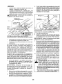
IMPORTANT:
Deck must be level sideto-side.
To obtain the best cutting results, the mower
blades should be adjusted so the front tip is
1/8" to 1/2" lower than the rear tip when the
mower is in its highest position.
_, CAUTION:
Blades are sharp, Protect
your hands wtth gloves and/or wrap blade
with heavy cloth.
• Raise mower to highest position.
• Position any blade so the tip is pointing
straight forward. Measure distance (B) to
the ground atfrontand reartip of the blade.
ADJUSTMENT
1. With all tires properly inflated and if your
lawn appears unevenIy cut, determine
which side of mower is cutting lower,
NOTE: As desired, you can raise the low
side of mower or lower the high side.
2. Go to side of mower you wish to adjust.
3. With a 3/4" or adjustable wrench, turn
lift link adjustment
nut (A) to the left to
lower the mower, or, to the right to raise
the mower,
_.. °o\
°\__
Turn nut tic
to raise mower
SIDE-TO-SIDE
\
I
° o/
_%'
• lffronttipofbladeisnotl!8"to
1/2" lower
than the rear tip, go to the front of tractor.
• With an 11/16" or adjustable
wrench,
loosen jam nut A several turns to clear
adjustment nut B.
• With a 3/4" or adjustable wrench, turn
front link adjustment
nut (B) clockwise
(Itighten) to raise the front of mower, or,
counterclockwise
(loosen) to lower the
front mower.
Turn nut left
to lower mower
NOTE: Each full turn of adjustment nut will
change mower height about 3/16".
4. Test your adjustment
by mowing some
uncut grass and visually checking the
appearance. Readjust, if necessary, until
you are satisfied with the results,
PRECISION
see steps 2
instructions
ADJUSTMENT
1. With aUtires properly inflated, parktractor
on level ground or driveway.
CAUTION:
Blades are sharp, Protect
your hands with gloves and/or wrap blade
with heavy cloth.
2. Raise mower to its highest position,
3, At both sides of mower, position blade at
side and measure the distance (A) from
bottom edge of blade tothe ground. The
distance should bethesame on both sides,
Tighten adjust nut
B to raise mower
Loosen adjust
nut B to lower
mower
Loosen iam nut A first
NOTE: Each full turn of the adjustment nut
will change mower height about 1/8".
• Recheck measurements,
adjust if necessary until front tip of blade is 1/8" to 1/2"
lower than the rear tip.
• Hold adjustment nut in position with wrench
and tighten jam nut securely against adjustment nut.
26
TO REPLACE
MOWER
DRIVE BELT
MOWER DRIVE BELT REMOVAL
1. Park tractor on a level surface. Engage
parking brake.
2. Lower attachment lift lever to its lowest
position.
3. Disengage belttension rod (K)from lock
bracket (L).
CAUTION: Belttension rodis spring loaded. Have afirm grip on rod and release slowly.
4. Remove screws (P) from R.H. and L.H.
mandrel covers and remove covers (Q).
5. Remove any dirt or grass clippings which
may have accumulated around mandrels
and entire upper deck surface.
6. Remove belt from electric clutch pulley
(M), both mandrel pulleys (R) and all idler
pulleys (S).
%
MOWER
DRIVE BELT INSTALLATION
1.
Install belt around both mandrel pulleys
(R) and around idler pulleys (S) as shown.
2. Install belt onto electric clutch pulley (M).
IMPORTANT:
Check belt for proper routing
in all mower pulley grooves.
3. Reassemble R.H. and L.H. mandrel covers (Q). Securely tighten all screws.
4. Engage belt tension rod (K) on locking
bracket (L).
A CAUTIO N: Belt tension rod is spring loaded. Have atight g rip on rod and engage slowly.
5. Raise attachment
lift lever to highest
position.
TO REPLACE
MOTION
DRIVE BELT
Park the tractor on level surface. Engage
parking brake. For assistance, there is
a belt installation guide decal on bottom
side of left footrest.
27
BELT REMOVAL I. Remove mower (See "TO REMOVE
MOWER" in this section of manual).
NOTE: Observe entire motion drive belt
and position of alt belt guides and keepers.
2. Disconnect clutch wire harness (A).
3, Remove anti-rotation link (B) on right
side of tractor.
4. Remove belt from stationary idler ((3)
and clutching idler (D).
5. Pull belt slack toward rear of tractor.
Remove belt upwards from transaxle
input pulley (F).
6. Remove belt downward from engine
pulley and around electric clutch (G).
7. Slide belt toward rear of tractor, off the
steering plate (t4)and removefrom tractor.
BELT INSTALLATION 1, Install new belt from tractor rear to
front, over the steering plate (H) and
above clutch brake pedal shaft (J).
2. Pull belt toward front of tractor and roll
belt around electric clutchand onto
engine pulley (G).
3. Pull belt toward rear of tractor. Carefully work belt down around transaxle
input pulley (F). Be sure belt is inside
the belt keeper,
4. Install belt through stationary idler (C)
and clutching idler (D).
5. Reinstall anti-rotation link (B) on right
side of tractor. Tighten securely.
6. Reconnect clutch harness (A).
7. Make sure belt is in all pulley grooves
and inside all belt guides and keepers.
8. Install mower (See "TO INSTALL
MOWER" in this section of manual).
TRANSAXLE
GEAR SHIFT LEVER NEUTRAL ADJUSTMENT
The transaxle should be in neutral when the
gear shift lever is in neutral (N) (lock gate)
position. The adjustment
mspreset at the
factory; however, if adjustment is needed,
proceed as follows:
1. Make sure transaxle is in neutral (N).
NOTE: When the tractor rear wheels move
freely, the transaxle is in neutral.
2. Loosen adjustment
bolt in front of the
right rear wheel.
3. Position the gear shift lever in the neutral
(N) position.
4. Tighten adjustment bolt securely.
NOTE: If additional clearance is needed to
get to adjustment
bolt, move mower deck
height to the lowest position.
Gearshift
Lever
_./_..._
TO REMOVE
WHEEL
FOR REPAIRS
1.
2.
Block up axle securely.
Remove axle cover, retaining ring and
washers to allow wheel removal (rear
wheels have a square key - Do not lose).
3. Repair ttre and reassemble.
NOTE: On rearwhee(s on[y: align grooves in
rear wheel hub and axle. Insert square key.
4. Repiacewashers
and snap retaining ring
securely in axle groove.
5. Reptace axle cover.
NOTE: To sea[ tire punctures and prevent
flat tires due to slow leaks, purchase and
use tire sealant fro m Sears. Tire sealant also
prevents tire dry rot and corrosion.
Washers
A
Reta,ning
Cover.
X
TO START
TERY
ENGINE
WITH A WEAK
(( _
BAT-
Ifyour batteryis too weakto start the engine, it
should be recharged. (See "BATTERY" in the
MAINTENANCE
section of this manual).
If "jumper cables" are used for emergency
starting, follow this procedure:
IMPORTANT:
Your tractor is equipped with
a 12 volt system. The other vehicle must also
be a 12 volt system. Do not use your tractor
battery to start other vehicles.
TO ATTACH JUMPER CABLES
1. Connectoneend
ofthe RED cabletothe
POSITIVE (+) terminal of each battery(AB), taking care netto short againsttracter
chassis.
2. Connect one end of the BLACK cable
to the NEGATIVE (-) terminal (C) of fully
charged battery.
3. Connect the other end of the BLACK
cable (D) to good chassis ground, away
from fuel tank and battery.
TO REMOVE
ORDER
CABLES,
REVERSE
1.
BLACK cable firstfrom chassis and then
from the fully charged battery.
2. RED cable last from both batteries.
__,
I _ Ira'[
BRAKE
If tractor requires more than five (5) feet to
stop at highest speed in highest gear on a
level, dry concrete or paved surface, then
brake must be serviced,
You may also check brake by;
1. Parktractoron alevel, dryconcreteorpaved
surface, depress clutch/brake pedal all
the way down an d engage parkin g brake.
2, Place gearshift lever in neutral position.
The rear wheels must lock and skid when
you try to manually push the tractor forward.
If the rear wheels rotate, then the brake
needs to be serviced. Contact a Sears or
other qualified service center.
_I_WARNING:
Lead-acid batteries generate explosive gases. Keep sparks, flame
and smoking materials away from batteries.
Always wear eye protection when around
batteries.
Adjustment Belt
..
TO CHECK
lm,1_
Sqy are___=_J
(Re_
Weak or Dead
Battery
28
Fully Charged
Battery
REPLACING
BATTERY
TO REPLACE HEADLIGHT
BULB
1. Raise hood.
2. Remove bulb holder from the hole in the
backside of the grill.
3. Replace bulb in holder and install bulb
holder securely back into the hole in the
backside of the grill.
4. Close hood.
n_asWARNING:
Do not short battery termiby allowing awrench or any other object
to contact both terminals at the same time.
Before connecting
battery, remove metal
bracelets, wristwatch bands, rings, etc.
Positive terminaf must be connected first to
preventspark=ng
from accidental
grou nding.
TO
1.
2.
3.
1. Lift hood to raised position.
2. Removetermina[
cover.
3.
Disconnect
BLACK battery cable then
RED battery cable and carefully remove
battery from tractor.
4.
I nstalt new battery with terminals in same
position as old battery.
Reinstall terminal coven
5.
6.
First connect RED battery cable to positive (+) battery terminal with bolt and nut
as shown. Tighten securely.
7.
Connect
BLACK grounding
cable to
negative (-) battery terminal with remaining bolt and nut. Tighten securely
Close hood.
8.
(_-"__
Headlight Wire
Negative
_.F_ .._
F_./ ._
)
nector
\_ ...(Black)
__
Terminal
4.
REMOVE HOOD & GRILL ASSEMBLY
Raise hood.
Unsnap headlight wire connector.
Stand in front of tractor. Grasp hood at
sides, tilt toward engine and lift off of
tractor.
When replacing hood, be sure to reconnect the headlight wire connector.
Cable
_
Cover .
Positive _,
(Red)I-
_'.,_--_b,-')
_
-_"__
_
ENGINE
TO ADJUST THROTTLE CONTROL
CABLE
The throttle control has been preset at
the factory and adjustment should not be
necessary Check adjustment as described
below before loosening cable. If adjustment
is necessary, see engine manual
/7
FRONT WHEEL TOE-IN/CAMBER
You r new tractor front wheel toe-in and camber is set at the factory and is normal. The
front wheel toe-in and camber are not adjustable. If damage has occurred to affect the
factorysetfrontwheeltoe-in
or camber, contact a Sears or other qualified service center.
INTERLOCKS
TO ADJUST CHOKE CONTROL
The choke control has been preset at the
factory and adjustmentshould not be necessary. If adjustment is necessary, see engine
manual.
AND RELAYS
TO ADJUST
Loose or damaged wiring may cause your
tractor to run poorly, stop running, or prevent
it from starting.
• Check wiring.
CARBURETOR
Yourcarburetor has been preset atthe factory
and adjustment
should not be necessary.
However, minor adjustment may be required
to compensate for differences in fuel, temperature, altitude or load. ffthe engine does
need adjustment, see engine manual.
TO REPLACE FUSE
Replace with 30 amp automotive-type
plugin fuse. The fuse holder is located behind
the dash.
29
Immediately prepare your tractor for storage
at the end of the season or if the tractor will
not be used for 30 days or more.
ENGINE
FUEL SYSTEM
A
,8_kWARNING:
Neverstore
the tractorwith
gasoline in the tank inside a building where
fumes may reach an open flame or spark.
Allow the engine to cool before storing in
any enclosure.
TRACTOR
Remove mower from tractor for winter storage. When mower is to bestored for a period
of t_me, clean _tthoroughly, remove all dirt,
grease, leaves, etc. Store in aclean, dry area.
I. Clean entiretractor
(See"CLEANING"in
the Maintenance section ofthts manual).
2. Inspect and replace belts, if necessary
(See belt replacement instructions in the
Service and Adjustments section of this
manual).
3. Lubricate as shown in the Matntenance
section of this manual.
4. Be sure that all nuts, bolts and screws
are securely fastened.
Inspect moving
parts for damage, breakage and wear.
Replace if necessary.
5. Touch up all rusted or chipped paint
surfaces; sand lightly before painting.
BA'I-I'ERY
IMPORTANT:
It is important to prevent
gum deposits from forming tn essential fuel
system parts such as carburetor, fuel hose,
or tank during storage. Also, alcohol blended
fuels (called gasohol or using ethanol or
methanol) can attract moisture which leads
to separation and formation of acids during
storage. Acidic gas can damage the fuel
system of an engine while in storage.
• Empty the fuel tank by starting the engine
and letting it run until the fuel lines and
carburetor are empty.
• Never use engine or carburetor cleaner
products in the fuel tank or permanent
damage may occur.
• Use fresh fuel next season.
NOTE: Fuel stabilizer is an acceptable alternative in minimizing the formation of fuel
gum deposits during storage. Add stabilizer
to gasohne in fuel tank or storage container.
Always foilowthe mix ratio found on stabilizer
container. Run engine at least 10 minutes
after adding stabt hzerto allowthe stabilizer to
reach the carburetor. Do not empty the gas
tank and carburetor if using fuel stabilizer.
ENGINE OIL
Dram oil (with engine warm) and replace
with clean engine oil. (See "ENGINE" in the
Maintenance
section of this manual).
CYLINDER(S)
1. Remove spark plug(s).
2. Pour one ounce of oil through spark plug
hole(s) into cylinder(s).
3. Turn ignition key to "START" positron for
a few seconds to distribute oil.
4. Replace with new spark plug(s).
- Fully charge the battery for storage.
• After a period of time in storage, battery
may require recharging.
• To help prevent corrosion
and power
leakage during long penods of storage,
battery cables should be disconnected
and battery cleaned thoroughly (see "TO
CLEAN BATTERY AND TERMINALS" in
the Maintenance
section of this manual).
• After cleaning, leave cables disconnected
and place cables where they cannot come
in contact with battery terminals.
• If battery
is removed
from tractor for
storage, do not store battery directly on
concrete or damp surfaces.
OTHER
• Do not store gasoline from one season to
another.
• Replace your gasoline can ifyour can starts
to rust. Rust and/or dirt in your gasoline
will cause problems.
• [f possible, store your tractor indoors and
cover itto give protection from dust and dirt.
• Cover your tractor with a suitable protective cover that does not retain moisture.
Do not use plastic. Plastic cannot breathe
which allows condensation to form and wilt
cause your tractor to rust.
IMPORTANT:
Never cover tractor while
engine and exhaust areas are still warm.
3O
TROUBLESHOOTING CHART:
See appropriate section in manual unless directed to Sears service center
PROBLEM
iWill not start
CAUSE
1
Out of fuel,
2
Engine not "CHOKED"
1
Fill fuel tank.
2
See "TO START ENGINE" in
Operation section.
3
Engine flooded.
3
Watt several minutes before
attempting to start.
4
Bad spark plug.
4
Replace spark plug,
5
Dirty air filter.
5
Clean/replace
6
Dirty fuel filter.
6
Replace fuel filter.
7
Water in fuel,
7
Empty fuel tank and carburetor,
refill tank with fresh gasoline and
replace fuel filter.
B
Loose or damaged wiring.
8
Check all wiring.
9
Carburetor
9
See "To Adjust Carburetor' in
Service and Adjustments section.
10
Contact a Sears or other quahfied
service center.
10
Hard to start
Engine will not
turn over
Engine clicks but
will not start
CORRECTION
properly.
out of adjustment.
Engine valves out of adjustment.
air filter.
1
Dirty atr filter.
t
ClearVrep[ace air filter.
2
Bad spark plug.
2
Replace spark plug,
3
Weak ordead battery.
3
Recharge or replace battery.
4
Dirty fuel biter.
4
Replace fuel filter.
5
Stale or dirty fuel.
5
Empty fuel tank and refill tank witt
fresh, clean gasoline.
6
Loose or damaged wlring.
6
Check all wiring.
7
Carburetor
7
See "To Adjust Carburetor" in
Service and Adjustments section.
8
Engine valves out of adjustment.
8
Contact a Sears or other qualified
service center.
1
Clutch/brake
1
Depress clutch/brake
2
Attachment
2
Disengage
3
Weak or dead battery.
3
Recharge or replace battery.
4
Blown fuse.
4
Replace fuse.
5
Corroded battery terminals.
5
Clean battery terminals.
6
Loose or damaged wtdng.
6
Check all widng.
7
Faulty Ignition switch.
7
Check/replace
ignition switch.
8
Faulty solenoid or starter.
8
Check/replace
solenotd or starter.
9
Faulty operator
switch(ca).
9
Contact a Sears or other qualified
sentice center.
out of adjustment.
pedal not depressed
clutch is engaged.
presence
pedal.
attachment
clutch.
1
Weak or dead battery.
1 i Recharge or replace battery.
2
Corroded batten] terminals.
2
Clean batten] terminals.
3
Loose or damaged wiring.
3
Check all wiring.
4
Faulty solenoid or starter.
4
Checldreplace
31
solenoid or starter.
TROUBLESHOOTING
CHART:
See appropriate section in manual unless directed to Sears service center
CAUSE
PROBLEM
Loss
of power
Excessive vibration
CORRECTION
1
Cutting too much grass,floe fast.
1
Raise cutting height/reduce
speed.
2
Throttle in "CHOKE"
position.
2
Adjust throttle control.
3
Build-up of grass, leaves and
trash under mower.
3
Clean underside of mower
housing.
4
Dirty air filter.
4
Clean/replace
5
Low oil level/dirty
5
Check oil Ievel/change
6
Faulty spark plug.
7
Dirty fuel filter.
7
8
Stale or dirty fuel,
8
Empty fuel tank and refill tank witf
, fresh, clean gasoline.
9
Water in fuel.
9
Empty fuel tank and carburetor,
refill tank with fresh gasoline and
replace fuel filter.
oil.
i6
10
Spark plug wire loose.
10
11
air filter.
oil.
Clean and regap or change spark
plug,
Replace fuel filter.
Connect and tighten spark plug
wire.
Dirty engine air screen/fins.
11
Clean engine air screen/fins.
!12
Dirty/clogged
12
Clean/replace
13
Loose or damaged wiring.
13
Check all wiring.
14
Carburetor
14
See "To Adiust Carburetor" in
Service and Adjustments section.
15
Engine valves out of adjustment.
15
Contact a Sears or ether qualified
service center.
muffler.
out of adjustment.
muffler.
1
Worn, bent or loose blade.
1
Replace blade, Tighten blade bolt.
2
Bent blade mandrel.
2
Contact a Sears or other
qualified service center.
3
Loose/damaged
3
Tighten loose part(s).
Replace damaged parts.
1
Check wiring, switches and
connections. If not corrected,
contact a Sears or other qualified
service center.
part(s).
Engine continues to 1
run when operator
eaves seat with
attachment clutch
engaged
Faulty operator-safety
control system,
Poor cut
1
Worn, bent or loose blade.
1
Replace blade. Tighten blade bolt.
2
Mower deck not level.
2
Level mower deck.
3
Buildup of grass, leaves, and
trash under mower.
3
Clean underside
housing,
4
Bent blade mandrel
4
Contact a Sears or other
qualified service center,
Clogged mower deck vent from
build-up of grass, leaves, and
trash around mandrels.
5
Clean around mandrels to
open vent holes.
presence
.....,,,,,
cutting
- uneven
32
H,
of mower
TROUBLESHOOTING CHART:
See appropriate section in manual unless directed to Sears service center
CAUS E
PROBLEM
Mower blades will
not rotate
Poor grass
discharge
1
Obstruction'in
2
Worn/damaged
3
Frozen idler pulley.
3
Replace td[er pulley.
4
Frozen blade mandrel.
4
Contact a Sears or other
qualified service center.
1
Engine speed toe slow.
1
Place throttle controJ in =FAST"
positron.
2
Travel speed too fast,
2
Shift to slower speed.
3
Wet grass.
3
Allow grass to dry before mowing
4
Mower deck not level.
4
Level mower deck.
i5
Headlight(s) not
working
(if so equipped)
Battery will not
charge
Loss of drive
CO RRECTIO N
Low/uneven
clutch mechanism.
1
mower drive beLt. 2
tire air pressure.
Remove obstruction.
Replace mower drive belt.
5
Check tires for proper PSI.
6
Worn, bent or loose blade.
6
Replace/sharpen
blade bolt.
blade. Tighten
7
Buildup of grass, Leaves and
trash under mower,
7
Clean underside
housing.
of mower
8
Mower drive belt worn.
8
Replace mower drive belt.
9
Blades improper]y installed.
9
Reinstall blades sharp edge down
10
Improper blades used.
10
Replace With blades listed in
this manual.
11
11
Clogged mower deck vent holes
from buildup of grass, leaves, and
trash around mandrels.
Clear= around mandrels to
open vent holes.
1
!Jght switch is "OFF".
1
Turn light sw=tch "ON".
2
Bulb(s) or lamp(s)
2
Replace bulb(s) or lamp(s).
3
Faulty light switch.
3
Check/replace
4
Loose or damaged wiring.
4
Checkwirmg
5
Blown fuse.
5
Replace fuse.
burned out.
tight switch.
and connections.
1
Bad battery cell(_).
1
Replace battery,
2
Poor cable connections.
2
Check/clean
3
Faulty regulator (if so equipped).
3
Replace regulator.
4
Faulty alternator.
4 ! Replace alternator.
all connections.
1
Debris on steering plate (if
equipped).
1
See "CLEANING" in the
maintenance section.
2
Motion drive beTt worn, damaged,
or broken.
2
Replace motion drive belt.
3
Axle key missing.
3
Install axle key at rear wheel. See
"TO REMOVE WHEEL" in the
Service and Adjustments section.
33
TROUBLESHOOTING CHART:
See appropriate section in manual unless directed to Sears service center
IPROBLEM
CAUSE
CORRECTION
Move throttle control between
half and full speed (fast) position
before stopping engine.
EngJne throttle control not so'
between haft and full speed (fast',
position before stopping engine,
Engine "backfires"
when turning
engine "OFF"
Engine dies when
;tractor is shifted
into reverse
1
Reverse operation system (ROS)
is not "ON" while mower or other
attachment is engaged.
1
Turn ignition key to ROS "ON"
I pos_t_on. See Operation section.
N££D HORF. H£LP?
i:
'F-
You'll find the answer
- Find this
and a[[ your
* Get answers
other
from our team
• Get a personaLized
• Find information
manage
and more on managemyltome.com
product
online.
of home experts.
maintenance
and tools
manuals
plan for your
to help with
home.
home projects.
home
brou£ht to you by Sea_rs
34
- for free!
SUGGESTED
GUIDE
FOR SIGHTING
SLOPES
FOR SAFE OPERATION
ONLY RIDE UP AND DOWN HILL,
NOT ACROSS HILL
15 DEGREES
MAX.
1
_
down the face of slopes, never across the face. go not mow
ARNING:
To avoid
serious
injury,
operate
tractor
and
slopes
greater
than 15
degrees.
Make
turns your
gradually
to up
prevent
tipping or loss of control, Exercise extreme caution when
changing direction on elopes,
t. Fold this page along dotted line indicated above.
2. Hold page before you so that its left edge is vertically parallel to a tree
trunk or other upright structure.
3. Sight across the fold in the direction of hill slope you want to measure.
4. Compare the angle of the fold with the slope of the hilt.
LO
00
Garanga ..........................................................
RegJas de Seguridad ......................................
Especfficaciones del Producto ........................
Montaje/Pre Operacidn ...................................
Operaci6n .......................................................
Mantenimiento ................................................
Garantia
GARANTiA
para
equipos
COMPLETA
tractores
36
37
40
41
47
54
Programs de Mantenimiento .......................... 54
Servicio y Ajustes ........................................... 59
Almacenamiento ............................................. 64
[dentificacidn de Prob]emas ........................... 65
Servicio Sears .............................. Contraporada
Craftsman
DE CRAFTSMAN
PeR DOS A[--,!OSdesde la fecha de compra, todas los partes no sustituibles de este equipo tractor estdn
garantizadas
centre cualquier defecto de material o mane de obra. Una porte no sustituible defectuosa
recibir& reparaci6n o reemplazo gratuito en case si la reparaci6n es imposible.
PeR CINCO AI_-JOSdesde la fecha de compra, el bastidor y el eje delantero de este equipo tractor estan
garantizados centre cualquier defecto de material o mane de obra. Un bastidor e eje delantero defectuoso
recibir_, reparaci6n o reemplazo gratuito en casa si ]a reparacibn es imposible.
DURANTE
g0 DiAS desde Ia fecha de compra, la bateria (una pare sustituible) de este equipo tractor
est_ garantizada centre cualquier defecto de material e rhone de obra (nuestra prueba comprueba que no
centendr,5 carga). Una bateria defectuosa recibir_ un reemplazo gratuito en case.
GARANTiA LIMITADA
est_ provisto)
DE POR VtDA ADIC1ONAL
en el EJE DELANTERO
DE HIERRO COLADO
(si
DURANTE EL TIEMPO EN QUE SE USE per el propietario original despu_s del quinto afro a par_ir de la
fecha de compra: el eje detantero de hierro colado (si est& provisto) de eete equipo tractos est& garantizado
centre cualquier ctefecto de materia] o mane de obra. Con el comprobante de compra, un eje detantero de
hierro eolado recibir& un reemplszo gratuito en case.
SERMIOlO
DE GARANTiA
Pars conocer los detalIes de Ia cobertura de garantia pars obtener una reparaci6n
llame al 1-800-659-59t 7 6 visite el sitio web: www. crafleman.com
En todos los cases anteriores, si el reemplazo
el mismo modelo o uno equivalente.
o reemplazo
gratuito,
es imposible, el equipo tractor ser_. sustituide sin cargo con
Toda ta cobertura de garantia anterior sere. nula si este equipo tractor se utiliza alguna vez pars bdndar
servicios comerciales o si se alquila a otra persona.
Esta garantra cubre (JN]cAMENTE defect_s de materia_ y man_ de _bra_ La c_bertura de garantia N_ incluye:
• Partes sustituibles (excepto la bateria) que se puedan desgastar per el use normal dentro deI periodo de
garantia incluso, pore sin [imitarse a, cuchillas, bujras, filtros de aire, correas y filtros de aoeite.
• Sercicios de mantenimiento est_.ndar, cambios de aceite a afinaciones.
• Reemplazo o reparacidn de neum&ticos per pinchazos causados por objetes externos come cloves,
espinas, tocones o vidrios.
• Reemplazo o reparacidn de neum_ticos o ruedas per desgaste normal, accidentes o per operaci6n o
mantenimiento
incorrectos.
°
Reparaciones
necesarias per abuse del operador incluso, pero sin limitarse a, defies causeries per
remolcar objetos que superen la capacidad del equipo tractor, chocar contra objetos que doblen el
bastidor, e! ensemble deI eje o el cigL_ef_ato sobrepasar la velocidad del motor.
• Reparaciones necesarias per negligencia det operador, inc]uso (pete sin limitarse a eI[o) defies eI_ctricos
y mecdnicos causeries per el almacenamiento
incorrecto, per no usar el grade y ]a cantidad correctos de
aceite de motor, per no mantener del mue[le libre de residues inflamables o per no mantener el equipo
tractor de acuerdo con las instrucciones que contiene el manual del operador.
• Limpieza o reparaciones
de] motor (sistema de combustible)
cuando se determina que se us6
combustible contaminado y oxidado (sarro). En general, el combustible debe usarse dentro de los 30
dias posteriores a su compra.
• Deterioro y desgaste normal de los acabados exteriores o suetituci6n de r6tu[os de productos.
Esta garantia Ie otorga derechos legales especfficos, y usted tambi_n puede toner otros derechos que
varian de un estado a otto.
Sears Brands Management Corporation, Hoffman Estates, IL 60179
36
_-PELIGRO:
Esta Maquina cortadora es capaz de amputar ias manosy los pies y de lanzar
objetos, si no se observan las instrucc]ones de seguridad sigulentes se pueden producir
lesiones
graves
o la muerte.
•
No maneie [a m_.qulna si no tiene la trampa
para c_sped completa, la canaleta de descarga
u otros dispositivos
de seguridad en su lugar
yen funcionamiento.
• Ralentizar antes de girar.
• Nuncadejar
una m&quina encendida sin vigilancia. Apagar siempre las cuchillas, porter el
freno de estacionam_ento,
parar el motor, y
quitar las Ilaves antes de bajar.
• Desenganche
las hojas cuando no est_ cortando c@sped. Apague el motor y espere hasta que
todas las partes se detengan per complete antes de Eimpiar la m&quina, retirar latrampa para
c_sped o destapar la canaleta de descarga.
_ILADVERTENCIA:
Siempre desconecte el alambre de la bujfa y pSnga[o deride no pueda entrar
en contacto con la bujia, para evitar et arranque
per accidente,
durante la preparaci6n,
el transporte, el ajuste o cuando se hacen reparaciones.
_ADVERTENCIA:
No avarice cuesta aba]o a punto muerto ya que podria perder el control de[tractor.
_,ADVERTENCIA:
Remolque
solamente
los
accesorios
recomendados
y conformes
a las
caractedsticas
_nd_cadas per el fabdcante
de su
tractor. Tenga cu_dado y prudencia al utilizar el
tractor. Ouando se encuentTe en un dechve, oper
utihzando exclusivamente
la velocidad m&s baja.
En case de un dechve una carga exceslva podria resultar peligrosa.
Los neum&ticos pueden
perder la tracci6n con e] suelo y hacerle pettier
el control de su tractor.
•
Hacer funcionar la m&quina
dla o luz artificial buena.
•
No bacer funcionar
lama, qu[na estando
los efectos de alcohol o droga.
_DVERTENC|A:
El tube de escape del motor,
algunos de sus constituyentes
y a{gunos componentes
de] vehiculo contienen o desprenden
productos
qulmicos
conoc=dos en el Estado de
California
come causa de c_.ncer y defectos a]
nacimiento
u otros dafios reproductivos.
•
Porter atenci6n
a[ tr_.fico euando
cerca de calles o se cruzan.
_tADVERTENClA:
Los berries, terminales yaccesorios relatives de la bateria contienen plomo
o compuestos
de plomo, productos
quimicos
conocidos en el Estado de California come causa
de c&ncer y defectos al nacimiento u otros daSos
reproductivos.
Lavar las manes despu_s
de
manipu|arios.
• Los dates indican que los operadores
a partir
de los 60 ar_os est&n afectados
per un gran
porcentaje de beridas re[ativas a la conducci6n
del cortac@sped.
Estos operadores
tendrian
que evaluar su habJlidad de hacer funcionar
et cortac_sped
de mode Io bastante seguro
para proteger a st mismos y a otras personas
de heridas graves.
I. FUNCIONAMIENTO
sSlo con la luz del
bajo
se opera
• Porter la m_ima
atenci6n al cargar o descargar la m_.quina en una caravana o caml6n.
• Uevar siempre galas de protecci6n cuando se
hace funcionar la m&quina.
GENERAL
• Leer, entender y seguir todas las instrucciones
sobre la maquina yen el manual antes de
empezar,
• No pener }as manes o los pies cerca de partes
giratorias o debajo de la m_quina, mantener
siempre limpia la abertura de descarga.
• Permitir el funcionamiento de la m&quina s61o
a aduItos que tengan familiaridad con las
instrucciones.
• Limplar el &rea de objetos come piedras,
juguetes, cables, etc, que pueden set recogidos y disparados con las cuchillas.
• Asegurarse de que el &rea est_ Iibre de otras
personas antes de ponerla en marcha. Parar
la mAqulna si algulen entra en el &rea.
• Nunca Elevarpasajeros.
• No cortar marcha arras al no ser absoiutamente necesario. Mirar siempre abajo y
delante mientras se precede atr&s.
• Nunca dirigir el material descargado hacia nadie. Evitar descargar material contra paredes
u obstrucciones. El mater=al podrla rebotar
hacia el operador. Parar las cuchiElas cuando
se pasan superficies de grava.
37
•
•
Seguir las recomendaclones
del fabricante
para los pesos y contrapesos
de las ruedas.
Mantener la m_quina libre de hierba, hojas u
otros escombros
que pueden tocar el tube de
escape/partes
de] motor calientes y quemarse.
No permitir
que el puente del cortac_sped
cargue hojas u otros residues
que pueden
causar acumulaciones.
Limpiar toda salpicadura de aceite o carburante
antes de hacer
operaciones
sobre [a m&qu=na o guardada,
Dejaria enfriar antes de guardada,
II. FUNCIONAMIENTO EN PENDIENTES
Las pendientes son el mayor factor de accidentes
relatives a la p6rdida de control y vuelco, que
pueden causar severas heridas o muerte. E[ funcionamiento en pendientes requiere una atenci6n
extra. Si no es posible hacer marcha atr&s an una
pendiente o si te sientes incomodo,
no [a cortes,
* Cortar hacia arriba y abajo de una pendiente,
no de mode horizontal.
,Poner
atenciones a los boyos, las ralces, los
belles, las pledras u otros objetos escondidos.
El terreno irregular puede volcar la m&quina.
La hierba alta puede esconder obst&culos.
•
Escoger
una velocidad
de mareha baja de
modo que no sea necesario pararse o cambiar
estando en una pendiente.
•Tener
el m&ximo cu_dado cuando se acerca
a cantos ciegos, arbustos,
&rboles u otros
objetos qua pueden impedir la vista de niSos.
•
No cortar la hierba moiada.
perder tracci6n.
IV. REMOLQUE
Las ruedas
pueden
Porter siempre una marcha cuando se est#.
en pendientes.
No poner en punto muerto eir
cuesta abajo.
• EvJtar arrancar, pararse o g_rar en una pendiente. Si las ruedas plerden tracci6n, desconectar
Ins cuchillas y proceder despaclo cuesta abajo
en la pendiente.
•
Mantener
todo los movimientos
en las pendientes lentos y gradual.
No hacer eambios
repentinos
de velocidad o direcc_Sn, ya que
pueden causar e! escape de la m#.quina.
• Poner la m&xirna atenci6n cuando la m&quina
funciona
con captadores
de hierba u otros
dispos_tivos enganchados;
pueden afectar {a
estabilidad
de la m_.qulna. No usar en pendlentes empinados.
• No intentarestab_I_zar
lam&quina
poniendo et
pie en el terraria.
•
No cortar cerca de bajadas, cunetas y onllas.
Las m__quina puede volcarse improvisamente
s1 una rueda est#, en el borde o se hunde.
,
• Seguir Ins recomendac_ones del productor con
respecto a los I[mites del equipo par remolcar
y el remolque en pendientes
• Nunca perrmtir que ni,fios u otras personas
est6n dentro del equ_po par remolcar.
• En pendientes, el peso del equipo remolcado
puede causar ra p6rd_da de tracci6n y la p_rdlda de control.
• Viajar despacio y dejar rn,_s distancia para
frenar.
V. SERVIClO
MANIPULACION
_,ADMER.TENCtA:
LOS NIt_OS
PUEDEN
SUFRIR DANOS CON EL usa DE ESTE EQUIPO. La Academia IEstadounidense
de Pediatrla
(American
Academy of Pediatrics)
recomienda
que s51o se permita a nir_os con una edad mfnima de 1 2 aSos manejar m_.quinas cortac6sped
manuales, y al menos de 16 a_os para manejar
tractores cortac_sped.
•
•
Si el operador no pone atenci6n a la presencia
de los nir_os pueden ocurrJr accidentes trAgicos.
Los nlSos a menudo est&n atraidos par ta m_quinay las act_wdad de cortar. No dar par hecho
de que los niSos se queden adonde estaban la
Qttima vez que los vistes.
• Mantener los niSos fuera det &tea de carte y
vigilados par un adulto responsable
que no sea
el operador.
•
•
•
la m&quina
Nunca dejar
quina_
Nunca quitar el tapSn de la gaselina o aSadir
carburante
con el motor en marcha,
dejar
enfriar el motor antes del abastecimiento
de
la gasolina.
Nunca abastecer
la m&quina al interior de un
local.
Qultar el equipo de gas del camion o caravana
y abastecerlo
en el terreno. S_ no es pasible,
abastecer dicho equipo con un contenedor port_.tll, rn&s bien que de un surtldor de gasotina.
• Mantener
la boquilia
a contacto
del borde
dee deposito de carburante
o Ia abertura del
contenedor
durante
toda la operacidn
de
abastec_miento.
No utilizar un dlspositivo con
boqu_lla cerrada-ab_erta.
si un ni5os
que los niSos manipulen
DE LA GASOLINA
Nunoa guardar
la m&quina
o el contenedor
del carburante
deride haya una llama abierta,
ch_spas o una luz pilate coma un calentador
de agua u otros dispositlvos.
• Nunca Henar los contenedores
al interior de
un vehlculo
o en una caravana
o camlSn
recubiertos
con un forro de p[#.stico. Colacar
siempre los contenedores
en el terraria lejos
del vehiculo cuando se est& Ilenando.
• Antes y durante Ja rnarcha atr__s, mirar adelante
y abajo para ver si hay niSos pequer_os.
• Nunca llevar nl&os, incluso si hay las cuchilfas
apagadas.
Podrian caer y herirse seriamente
o interferir con el funcionam_ento
seguro de la
m#.quma los nir_os que se han Ilevado precedentemente
pueden aparecer de pronto en el
_rea de carte par otto paseo y set atropellados
o tumbados par la m_quina.
•
SEGURA
Para evitar heridas personales
o da_os alas
cosas, porter el m_iximo cuidado a la hora de
manipular la gasolina. La gasohna es extremamente inflamable y los vapores son explosivos.
• Apagar todos los cigarri]fos, cigarros, pipas y
otras fuentes de ignici6n.
• Usar s61o contenedores
para gasolina aprobados.
!11. NII_IOS
Estar alerta y apagar
entra en el &rea.
Remolcar s6lo con una ma.qu[na que tenga un
gancho d_seSadopara remolcar. Enganchar el
equipo o remolcar s6ro en el punto dispuesto
al efecto.
• Si se vierte carburante
sabre fa ropa, cambiarse la ropa inmediatarnente.
• Nunca Ilenar el dep6sito m_-s de Io debido.
Volver a colocar el tapSn del gas y cerrar de
modo firme.
la m&-
38
OPERACIONES DE SERVICIO GENERALES
• Nunca hacer funcionar la m&quina en un _rea
cerrada.
• Si se golpea un objeto ajeno, hay que pararse
e inspeccionar la m_.quina. Reparar, si es
necesano, antes de vo]ver a porter en marcha.
• Nunca hacer ningfin ajuste o reparaci6n con
el motor en funci6n.
• Verifique los componentes de la trampa pare
c@spedy la canaleta de desearga con frecuenciay sustituya con repuestos recomendados
per el fabricante cuando sea necesado.
• Las cuchillas del cortac6sped son afiladas.
Envolver la cuchilla, ponerse guantes y poner
la m_,Jma atenci6n cuando se hacen operaciones en elias.
• Mantener todas las tuercas y pernos apretados
para asegurarse de que trabaja en condiciones
seguras.
• Nunca modfficar los dispositivos de seg uridad.
Centre[at su correcto funcienamiento regularmente.
• Mantener Eam&quina libre de hierba, hojas
u otros residues acumuEados. Limpiar [as
salpioaduras de aceite o carburante y quitar
cualquier cosa mojada con carburante. Dejar
que la m_.quina se enfrie antes de guardarla.
@@@@@
• Controlar el funeionamientodel freno frecuentemente. Ajustar y hacer las operaciones de
mantenimiento cuando eso sea necesario.
•Estar alerta y apagar [a m&quina si un nifies
entre en el &rea.
• Mantener y sustituir las etiquetas de seguridad
e instrucoi6n, cuando sea necesario.
• Asegurarse de que el _.rea est@libre de otras
personas antes de ponerla en mareha, pare la
m_quina si alguien entra en el &tea.
• Nunca llevar pasajeros.
• No cortar marcha arras al no set absotutamente
necesario. Miter siempre abajo y delante
mientras se precede atr_s.
• Nunca l[evar niSos, inc[uso si hay las cuchflEas
apagadas. Podfian caer y hedrse seriamente
o interferir con el funcionamiento seguro de la
m_quina, los nihos que se hen [levado precedentemente pueden aparecer de pronto en el
_.reade corte per otto paseo y ser atropellados
o tumbados per la m_quina.
• Mantener los nifios fuera del __reade corte y
vigilados per un adu]to responsabie que no sea
el operador.
39
• Antesydurante lamarchaa_'&s, miraradefante
y abalo para ver si hay nifios pequefios,
• Cortar hacia arriba y abajo de una pendiente
(15= M_), no de mode horizontal
• Eseoger una velocidad de marcha baja de
mode que no sea necesario pararse o cambiar
estando en una pendiente.
• Evitar arrancar, pararse o girar en una pendiente. Si las ruedas pierden traceibn, desconectar
las cuchillas y preceder despaeio cuesta abajo
en la pendiente.
• Si la m&quina se pare mientras va cuesta
arriba, deseonectar [as cuchillas, porter la
marcha atr&s y ir hacia atr_.s despaeio,
• No girar estando en pendientes si no es necesario, y luego girar despacio y gradualmente
cuesta abajo, si es posible.
• AI cargaro descargar la m_.quina, no sobrepase
ei _.ngu[o m_ximo recomendado de 15°.
ESPECIFICACIONES DEL PRODUCTO
Capac]dad y Ttpo
de Gasolina,
4,0 Galonesi15,14
L
Regular Stn PIome
Ttpo de Aceite
(API' SG-SL)"
SAE 10W30 (sobre 32°F]0°C)
SAE 5W30 (deabajo 32°F/0°C)
Capacldad
Ace_te
Con Filtre'
de
Bujia
Velocidad de
Recamdo
(MphiKph)
Tors=6n del Pemo
de _aCuchilla
cercano tiene d_sponible amortiguadores
de chlspas para el silenciador. (Vea la secci6n de Partes
de Repuesto en el manual Ingles del dueSo.)
64 Oz.I1 ,£6 L
Champion
(Abe_ura'
RC12YC
030"/0,76
Marcha
Adelante:
1st
2nd
3rd
4th
5th
6th
0- t
At_s
Sistema de
Carga:
Bateria.
En el estado de California, la ley exige 1oanterior
(Secci6n 4442 del "California
Public Resources
Code"). Otros estados pueden contar con otras
leyes parecidas.
Las leyes federales se aplican
en la tlerras federales. Su centre de Servicio m_s
ACUERDOS
DE PROTEGCION
LA REPARACION
ram)
1.0/1,6
1.4/2,3
2.1/3,4
3.1/5,1
4,0/6.4
5.1/8,2
.6/2,6
CongratuJaciones
per su buena compra
Su
nuevo producto
Craftsman®
est& diseSado y
fabncado
para func_onar
de mode liable per
muchos aSos. Pare come todos los productos,
puede necesitar alguna reparaci6n
de tanto en
tanto. En este case tener un Acuerdo de Protecc_6n para la Reparac_6n puede hacerles ahorrar
dinero y fastidios.
15 A @ 3600 RPM
Amp]Hr.
Min. CCA:
Modelo Tamar_o:
45-55 Ft. Lbs.i62-75
Cempre ahora un Acuerdo de Protecci6n para la
Reparacl6n
y prot_gese
de mo[estias y gastos
inesperados.
28
230
UIR
Un Acuerdo
Nm
FELICITACtONES
per la compra de su tractor. Ha
side d=sef_ado, planificado y fabricado para darle la
major confiabihdad y el mejor rendimiento posible.
En el case de que se encuentre
con cualquier
problema qua no pueda solucionar
f_tcilmente,
haga el favor de ponerse en contacto
con un
centre de servJcio Sears o con un otro centre de
serv=cio cuaJiflcado. Cuenta con representantes
bien capacitados
y competentes
y con las herramientas adecuadas
para darle servicio o para
reparar este tractor.
Haga el favor de leer y de guardar este manual
Estas tnstruc-c=ones le permitir__n montar y mantener su unidad en forma adecuada.
Siempre
observe las "REGLAS
DE SEGURIDAD
"
RESPONSABIUDADES
DEL
PARA
incEuye los puntos siguientes:
• Servicio
exper_o de nuestros I2.000 especialistas profes_onales
en la reparacidn,
• Servieio
ilimitado
sin cargo alguno
para
Ias partes y [a mane de obra sobre todas las
reparac[ones
garantizadas.
• Sustituci6n
del producto
si su producto
garantizado
no puede ser arreglado.
• Deaouento
de110% sobre el precto corriente
del servicio y de las partes relativas aE servicio
no cubiertas par el acuerdo; tambi6n el 10%
menos sobre el precto corriente de un control
de mantenimiento
preventive.
• Ayuda r_pida per tel_fono
- soporte tetef6nico per parte de un representante
Sears sobre
productos que requieren un arregto en casa, y
adem#.s una programaci6n
sobre los arreglos
m&s convenientes.
Cuando se ha comprado
el Acuerdo, basra con
una Ilamada teEef6nica para programar el servicio.
Puede llamar cuando quiera, dia y noche o fijar
en linea una cita para obtener el serv_cto_ Sears
tiene m&s de 12.000 especialistas
profesionales
en ta reparaci6n,
que tienen acceso a m_.s de
4.5 mtllones de partes y accesorios
de calidad.
CLIENTE
• Lea y observe las reglas de seguridad.
• Siga un programa
regular de mantemm_ento,
cuidado y use de su tractor.
• Siga las instrucciones
descritas en Jas sacclones "Mantenimiento"
y "Almacenamiento"
de este manual.
• Utihce prendas
de seguridad
adecuadas
al
manejar la mAquina, [ncluidos (come rain[me)
calzado de seguridad, galas protectoras y protecci6n auditiva.
No utilice pantalones
cortes
yio calzado abierto cuando corte fa hierba.
• Informe s_empre a alguien de que se d_spone
a cortar la hterba en el exterior.
Este es el tipo de profes_enalidad
con que puede
contar para ayudar a alargar
ra vida del producto que acaba de comprar, per muchos aSos.
iCompre hey su Acuerdo de Protecct6n
para la
Reparaci6n !
Se aplioan algunas limitaciones
y exclusiones.
Para conocer los precios y tenet m_s Infermacibn, Ilame al 1-800-827-6655.
_ADVERTENCIA:
Este tractor viene equlpade
con un motor de combusti6n
interna y no se debe
usar sobre, o cerca, de un terreno no desarrollado
cubierto de bosques, de arbustos o de c@sped,
o manes que el sistema de escape del motor
venga equ_pado con un amortiguador
de chispas
que cumpla con las leyes locales o estatales (si
existen). Si se usa un amortJguador de chispas,
el operador debe mantenerlo
en condJciones de
trabajo efic]entes.
SERVICIO
DE INSTALACION
SEARS
Para la instalaci6n profes_onal Sears de aparatos de casa, puertas de garaje, cafentadores de
agua y otros _rnportantes articulos para la casa,
en U.S.A Ilamar a
1-800-4-MY-HOME®
40
©
Rueda Delantera De La Segadora
Segadora
(2) Conjunto
_\
de esiabones
\\
de levantamiento
(5)Arandela1-3/16" traseros
_'_
(1) Abrazadera
pequefio
(1) Perno
(I) 1-1/4"
Arandela
_'_
de retenci6n
_
\\
(1) Eslabones
"_\
de levantamiento
delanteros
(1) Rueda
(1) 318-16"
Tuerca
_
(5) Abrazadera
grande de retenci6n
Si Los Tiene
(1) Barra
Antiosci|aci6n
(1) Tubo de desagQe
(1) 3/4"
Arandela
Llaves
(21 Llaves
(1) Abrazadera
pequefio
de retenci6n
41
Hoja de pendiente
Su tractor nuevo ha side montado en la _brica con la excepciSn de aquellas partes que no se han mentado per razones de envlo. Para asegurarse que su tractor funcione en forma adecuada y segura todas
las partes y los artfculos de ferreteria que se monten tienen que ser apretados en forma segura. Use [as
herramientas correctas, seg0n sea necesario, paraasegurarse de que est_n apretados en forrna segura,
HERRAMIENTAS
NECESARIAS
PARA
EL MONTAJE
Un juego de llaves de tube facilitar& el montaje.
A contlnuaclSn
se enumeran los tamar_os de las
Naves est&ndar.
(2) Llaves de 7/16"
Cuchltlo
(1) Llaves de 1/2"
Medidor de presiSn
(1) Llave de 3/4 <'
Pinzas
(1) Montura de 3/4 pulg. con mando de trinquete
(t) Llaves de 1/2"
Linterna
Cuando en este manual se mencionan los t_rmnnos"mano derecha" o "mane =zquierda" se refiere a
cuando usted se encuentra en la posiciSn de operacion (sentadoia detr&s del volante de dlrecciCn).
PARA REMOVER EL TRACTOR DE LA
CAJA DE CARTON
DESEMPAQUE
•
LA CAJA
DE CARTON
Remueva todas las partes sueltas que estCn
accesibles,
y las cajas de partes, de la caja
de cartCn grande.
Cortar ale largo de las lineas de puntos en todos
los cuatro paneles de cartCn. Remover los paneles de c_erre y aplanar los paneles laterales.
Remueva
Ja segadora y los materiales
de]
emba[ager
Revise si hay partes sueltas adicionaFes o
cartbn y rernuCvalas.
ANTES
DE REMOVER
LA CORREDERA
VERIFIQUE
1.
Levante
LA
EL TRACTOR
DE
BATERiA
del capote
ala
posicibn
L
_--_-_
_IADVERTENCIA:
Antes de empezar,
leer,
entender y seguir todas las instrucc_ones presentes en la secciCn Operac_ones de este manual.
Asegurarse
que el tractor est6 en un area bien
ventilada.
Asegurarse
que la zone delante del
tractor est_ libre de otras personas y objetos.
PARA HACER RODAR EL TRACTOR
FUERA
DE LA CORREDERA
(VEA LA SECClON
DE
LA OPERACION
PARA LA LOCALIDAD
Y LA
FUNCION
DE LOS CONTROLES)
1
Levante la palanca de levantamiento del accesorio a su peslciCn m_s alta.
2. Suelte el Irene de estac_onamiento
pres_onando el pedal del ernbragueifreno.
3. Ponga la palanca de cambios en fa posiciCn
de neutro
4. Haga rodar el tractor hacla delante fuera de
la corre-dera.
Continuer con las siguientes instruccnones.
ACCIONE
LA PALANCA
DEL FRENO
DE ESTACIONAMIENTO
Y LA PALANCA
DE LEVANTAMIENTO
DEL ACCESORIO
INFERIOR
Presione el pedal de embrague/freno
comp[etarnente haste abalo y mantCngale apretado.
Tire y mantenga la palanca del freno de estacionamiento
hacia arriba, libere la presiCn del
pedal de embrague/freno
y, luego, suelte la
palanca del frenode estacionamiento.
El pedal
debe permanecer
en posiciCn de frenado.
Aseg_rese de que el freno de estacionamiento
mantendr_, asegurado
el tractor.
_..-"/
AJUSTE EL ASIENTO
1. Si_ntese sobre el asiento.
2.
pare trabar el asiento
AVISO: Ahora puede rodar su tractor fuera de la
corredera. S=ga las siguientes _nstrucciones pare
remover el tractor de la corredera.
1.
Para instale
Ea bateda,
y cable
de la
bateria, realice el procedimjento
descrito en
"REEMPLAZAR
LA BATERIh_' del capitulo de
Servicio y Ajustes
de este manual.
Etlqueta_
Descoaecte
la palanca
en la posiclSn.
INSTALE LA SEGADORA
levantada.
AVISO: Siesta baterfa esta utilizada despuCs del
rues y afio indicado sobre la etiqueta (ta etiqueta
que se encuentra entre los termina[es),
cargue la
bater[a per un minimo de una hera a 6-I0 amps
(Vea "BATERIA" en la secciCn de Mantenimento
de este manual).
•
3.
Levante la palanca de[ ajuste (A) hacia arriba
y mueva el asiento haste que alcance una
posiciCn cCmoda que le perm_ta presionar comp[etamente sobre et pedal del embragueifreno.
42
_lt PR ECAUCION: La palanca de levantamiento
est&accionada porresorte. Sost6ngalafirmemente
apretada, b&jela [entamente y eng_nchela en la
posici6n m&s baja. La palanca de levantamiento
se encuentra en el lade izquierdo de la defensa.
3. GIRE EL VOLANTE HAC/A LA IZQU,IERDA
Y UBIQUE LA CORTADORA DE CESPED
EN SU LUGAR
Gire el volante compLetamente hacia la
izquierda y ubique la cortadora de c6sped
en el lade derecho del tractor con el blindaje
deflector (Q) a la derecha.
Parte Delantera
2.
ARME LA RUEDA CALIBRADORA DELANTERA {W) EN LA PART,E DELANTERA
DE LA CORTADORA DE CESPED
"_'Transeje
Parte Trasera
4,
DESLICE
DEBAJO
Q. Blindaje Deflector
LA CORTADORA
DEL TRACTOR
DE C#_-SPED
Lleve lacorrea hacia adelante y verifique que
su t_ayectoriaseacorrectaentedos
Iossurcos
de la polea de la cortadora de c_sped.
H, Escuadra De La Cortadora De C6sped
Oelantera
Rueda Calibradora Delantera
Pemo Con Resalto
Arandefa De 1-1/4
Tuerca De Seguridad De 3/8-16
NOTA: Aseg[irese de qua los brazes de
suspensi6n lateral de la cortadora de c6sped (A)
est6n orientados hacia adelante antes de deslizar
la cortadora de c6sped debajo del tractor,
Deslice la eortadora de c@sped debajo del
tractor hasta qua se encuentre centrada
debajo del tractor.
W.
X.
Y.
Z.
Cortadora De C6sped
B. Resorte De Retenci6n
C. Esfabones De Levantamiento Traseros
D. Escuadra Trasera Derecha De La Cortadora
De C6sped
E. Conjunto De Eslabones De Levantamiento
Delanteros
E Escuadra De Suspensi6n Delantera
H. Escuadra De La Corladora De C6sped
Delantera
L Escuadra Trasera fzquierda De La
Cortadora De C6sped
K. Varilla Tensora De La Correa
L Escuadra De 8[oqueo
M, Polea Del Embrague Del Motor
Q. Blindaje Deflector
S. Barra Antibatanceo
W, Rueda Callbradora Delantera
43
Haga osoilar el extremo
con la arandela
integrada de la barra antibalanceo
(S) hacia
la escuadra de la plataforma de la cortadora
de c_sped en el lado derecho de la cortadora.
Inserte el extremo con la arandela _ntegrada
de la barra en el agujero de la escuadra
trasera de la cortadora de e@sped (D). Mueva
Ja cortadora de c@sped segSn sea necesatio
para _nsertar el extremo
con la arandela
integrada de la barra erl la escuadra trasera
de Ja cor[aclora de c_sped (D).
Asegure con u na arandela pequeSa y un resorte de retenci6n pequeSo, como se ilustra.
A.
Q
5.
Brazos De Suspensi6n
Cortadora
De C6sped
Blindaje Deflector
SI LATIENE,
INSTALE
ANTIBALANOEO
(S)
Lateral
LA BARRA
BARRA ANTIBALANCEO
Hacia Et
nseje
Extremo
En 90 °
Hacia
..
De La
(S)
La Plataforma
De C6sped
De LaCortadora
_f-_
Extremo
Con
Arandela
V]
D.
[_'
Integrada
S.
Desde el lado derecho de la cortadora
de
c6sped, inserte primero elextremo en90°de la
barra antibalanceo
(S) dentro del agujero de la
escuadra de transeje (7-), u bicado cerca de la
rueda trasera izquierda adelante del transeje.
NOTA: Puede resultar _ti! usar una Jinterna.
I
6.
Escuadra
Trasera
Derecha
Cort.adora De C_sped
Barra Antibalanceo
De ka
T
Escuadfa Transeje
i
INSTALE LOS BRAZOS DE SUSPENSION
LATE RAL DE LA CORTADORA
DE ClaSPED
(A) EN EL CHASIS
Ubique el agujero de/antero
del braze de
suspensi6n
lateral (A) sobre la chaveta en la
parte exterior del chasis del tractor y asegure
con una arandela
grande y un resorte de
retenci6n grande (B).
Repita
en e] lado opuesto
del tractor.
Escuadra De Transeje (T)
Ubicada Entre Las Ruedas
A.
B.
D.
7.
NOTA: Dependiendo del modelo, la escuadra (T)
puede set diferente de la que se ilustra, pero el
agujero para la barra antibalanceo estar& en la
misrna posJci6niubicaci6n.
44
Brazos De Suspens_6n
Cortadora De Cesped
Resorte De Retenci6n
Escuadra
Cortadora
Lateral
Tras-Era Derecha
De C@sped
De La
De La
INSTALE LOS ESLABONES
DE LEVANTAMIENTO TRASEROS
(C)
fnserte el extremo de varilla del eslab6n de
levantamiento
trasero (C) dentro del agujero
(U) en el brazo de suspensi6n del eje de levantamiento del tractor y haga oscilar el eslab6n
hacla abajo hacia la cortadora
de c_sped.
i
Mu6vase haste el lade izquierdo de la cortadora e inserte un resorte de retenci6n grande
(G) a trav6s del agujero del eslab6n delantero
(E) detr&s de la escuadra de suspensi6n
delantera (F).
Inserte el otro extreme del eslab6n (E) en el
agujero de laescuadra derecha delacortadora
de c6sped (H) y asegure con una arandela y
un resorte de retenc[6n pequeSo (J).
Levante [a esquina trasera de la cortadera de
c6sped y ub_quela ranuraen elconjunto deeslabones sobre la chavetaen
fa escuadratrasera
de ia cortadera (D);asegure
con una arandela
grande y un resorte de retenci6n grande.
Repita en el lade opuesto del tractor.
NOTA: Requiere levantar la plateform&
9. INSTALE LA CORREA EN LA POLEA DEL
EMBRAGUE DEL MOTOR (M)
•
Desenganche la varilla tensora de la correa
(K) de la escuadra de blequeo (L).
•
lnstele la correa en la polea de] embrague
del motor (M)
O.
D.
'
U.
8.
•
,
Eslabones De Levantamiento Traseros
Escuadra Trasera Derecha De La
Cortadora De C6sped
Agujero
INSTALE EL ESLABON DELANTERO (E)
Gire el volante haste ubicar las ruedas derechas en posici6n de avance.
Desde la parte delantera del tractor, inserte el
extreme de varilla del eslab6n delantero (E) a
trav_s del agujero delantero de la escuadra
de suspensi6n delantera del tractor (F).
Del Eslab6n
DeLantero
M,
Embrague
De_ Motor
1MPORTANTE: Vermque que la trayectoria de
la correa sea correcta en todos los surcos de la
polea de la certadora de c@spedy debajo de las
cubiertas de mandril.
';
'
/'-_
j_
/
\
•
Enganche la varilla tensora de la correa (K)
en la escuadra de bloquee (L).
PRECAU C,16N:la varillatensora de la cerrea
est& accionada per rosette. Sostenga la variIla
firmemente apretada y eng&nchela lentamente.
•
Eleve la palanca de levantamiento del accesorio hasta la posici6n m&_ima.
Si es necesario, ajuste Ins rueditas def calibre
antes de pener en funcionamiento la cortadora, corno se ilustra en el capitulo de Manejo
de este manual.
PARA REEMPLAZAR LA CORREA
DE LA SEGADORA
Realice el procedimiento descnto en "PARA
REEMPLAZAR LA CORREA DE LA CUCHILLA
DE LA SEGADOR_' del capitulo de Servicio y
Ajustes de este manual.
F. Escuadra De Suspensi6n
Delantera
G. Resorte De Retenci6n Grande
H. Escuadra De La Corfadora De C6sped De[antera
J. Resorte De Retenci6n PequeSo
M, Po]ea Del
ue Del M¢
45
REVISION
DE LA PRESION
DE LAS
LLANTAS
Las Ilantas en su unidad fueron infJadas demasiado en la f_.brica por razones de env{o. La
presi6n de las llantas correctas es importante
para obtener el mejor rendimiento en eJcorte.
• Reduzca la presi6n de los neum&ticos a la PSi
que se indica en estos.
REVISION
DE LA NIVELACION
DEL
CONJUNTO
Para obtener los mejores resultados en el carte, la
caja de ta segadora tiene que estar hive[aria en la
forma adecuada. Vea"PARA NIVELAR LA CAJA
DE LA SEGADOR,_' en la seccibn de Servicio y
Ajustes de este manual.
REVISION DE LA POSICION ADECUADA
DE TODAS LAS CORREAS
Vea las figuras que aparecen para cambiar las
correas de impulsiSn de la cuchi[la de la segadora y de movimiento en la secci6n de Servicio y
Ajustes de este manual. Venfique que las correas
slgan su paso correcto.
REVISION
DEL SISTEMA DE FRENOS
Una vez que usted haya aprendido a manejar su
tractor, venfique que el freno func_one correctamente. Ver "PARA VERIF[CAR SI FUNCIONA
BIEN EL FRENO" eo e[ capitu]o de servieio y
ajustes de este manual.
46
t/fLISTA
DE REVISION
Antes de operar y de disfrutar de su tractor nuevo,
le deseamos que reciba el mejor rendimiento y la
mayor satisfaccion de este producto de calidad.
Haga el favor de revisar la lista a continuacion:
J" Se han comp[etado todas las instrucciones de
montaje.
J" No quedan partes sueltas en [a caja de cart6n.
•/" La baterfa est& preparada y cargada en forma
adecuada.
J" El asiento ha redo ajustado en forma c6moda
y apretado en forma segura.
,/! Todas las IIantas ban sido infladas en forma
adecuada. (Para fines de envfo, las Ilantas se
inflaron demasiado en la f&brica.)
_" AsegSrese que el conjunto segador este
niveEado en forma adecuada, de lado a lado
y desde adelante hacia atr&s, para obtener los
mejores resultados en el corte. (Las Ilantas
tienen que estar inf[adas en forma adecuada
para la nivelaci6n.)
J" Revise [as correas de impulsi6n y de la
segadora. AsegSrese que recorran el paso
adecuado aJrededor de las po]eas y dentro
de todos los fljadores de las correas.
_" Revise el alarnbrado. Fijese que todas las
conex_ones todavia est_n seguras y que los
alambres est_n sujetos en forma adecuada.
AI misrno tiempo que aprende a como usar su
tractor, preste atenciSn extra a los puntos de
importancia que se presentan a continuaci6o:
t/" El aceite de! motor t=ene que Ilegar al nivel
adeouado.
vf El estanquedecombustibletienequeestarlteno
con gasolJna sin plomo regular, nueva y limpia.
J" Familiaricese con todos los controles - su
ubicaci6n y su funci6n. Op_relos antes de
hater arrancar el motor.
_" Aseg_rese que et sistema de frenos est6 en
una condici6n de operaci6n segura.
J" Asegurarse de que el Sistema de Presencia
del Operador y el Sistema de Funcionamiento
Atr&s (ROS) funclonan de modo adecuado
(Ver las Secciones de Funeionamiento y
Mantenimiento en este manual).
Estos s{mbolos pueden aparecer sobre su tractor o en ]a literature proporcionada con el producto.
Aprenda y comprenda sus significados.
R
N
MARCHA ATRAS
NELFrRO
H
L
ALTO
BAJO
I'-,I
ESTRAi_GULAG|ON
RAPIDO
LENTO
6
MOTOR
APAGADO
MOTOR
MOTOR
FRENODE
ALTURADE LA LEVANTAMIENTO
SISTEMA ENCENDIDO EN MAR€HA ESTAClONAMIENTO SEGADORA DE LA SEGAOORA
FUNG]ONAMIENTO
ATRAS (ROS)
LUCES
ENSENDIDAS
COMBUST|BLE
ACGESORIODEL
EMBRAGUE
ENGANCHADO
BATERIA
MARCHA
ATR/_S
MAROHA
HACIA ADELANTE
PALANCADEMANDO
CRUCERO
PEDALDEFRENO/
DE EMBRAGUE
ACCESORIODEL
PELIGRO,GUARDELAS
MANDSY LOS PIESLEJOS MANTENGAEL
EMBRAGUE
AREA DESPEJADA
DESENGANOHADO
_/ea
I_ secc=6n
PELIGROSDE
PENDIENTES
de [as rag[aS
de segurldad)
PELIGRO
indica un
pellgro que,
sl no se evita,
provoca muerte
o [esiones
graves.
ADVERTENCIA tndica un peligro que, si no se evita,
puede provocar roberts o Issiones graves.
RUEDA LIBRE
{So[amente para los
rnodebs automabco)
PRECAUC|6N
un pQEgroque,
si no se evi{a,
puede provocarindica
lesiones
|igeras o moderadas.
PRECAUCION cuando se utiUza sin el simbolo de av[so,
indica una s=tuaci6n que puede provocar defies al
tractor y/o al motor.
&
No segulr las siguientes instrucciones
pL_edeprovocar hendas o muerle. Los
simbolos de aviso de seguridadse ul=lizarl
pare identlflsar informaclones de seguridad
relatives a peltgros que puedenprovocar la
muerte, heridas graves y/o da_,os ala
m&quina.
_1_
SUPERFICIES CALIENTES mdica un pnligro que,
si no se evita, puede provosar la muer_e, lee[ones
graves y/o danes a la maquina.
FUEGO indica un peligm que, si no se evita, puede
provosar la muerte, les[ones graves y/o danes
a la m_quina.
47
FAMILIARICESE
CON SU TRACTOR
LEA ESTff MANUAL LAS REGLAS DE SEGURIDAD ANTES DE OPERAR
SU TRACTOR
Compare las ilustraciones con su tractor para familiarizarse con las ubicaciones de los diversos
controles y ajustes. Guarde este manual para referenc_a en el futuro.
Nuestros
tractores cumplen con los estandares
de seguridad
American
Natioaal Standard Institute.
{A) PALANCA DEL LEVANTAM|ENTO
DEL ACCESORIO
- Se usa para levantar, bajar y ajustar
el conjunto
segador
o los dema.s accesonos
montados en su tractor_
(B) PEDAL DEL EMBRAGUE!FRENO
- Se usa
para desembragar
y frenar el tractor y para hacer
arrancar el motor.
(C) PALANCA
DFL FRENO
DE ESTACIONAMIENTO - Asegura el pedaE deJ embrague/freno
en la posic=Sn del freno.
(D) CONTROL DE ACELERACION
- Se usa para
controlar la velocidad del motor.
(15) INTERRUPTOR
DEL EMBRAGUE
DELACCESORIO
- Se usa para enganchar las cuchillas
segadoras,
o los dem_.s accesorios
montados
en su tractor.
(F) INTERRUPTOR
DE IGNICION _ Se usa para
hacer arrancar o hacer parar el motor.
del
(G) S[STEMA
DE FUNCIONAMIENTO
HACIA
ATRAS (ROS) EN POSICION "ON" - Perrnite [a
operaci6n del conjunto segador o otto accesorio
accionado
mientras queen roves.
(H) INTERRUPTOR
DE LA LUZ - Enciende y
apaga las luces delanteras.
(J) PALANCA
DE MANDO
CRUCERO
-Se
utiliza para fijar el movimiento
hacia adelante del
tractor a la velocidad deseada sin apretar el pedal
de marcha atr&s.
(N) CONTROL DE ESTRANGULACION
- Se usa
cuando se hace arranoar un motor frio.
(P) DIS.POSIT|VO
DE AVlSO DE SERV|CIO
/
CRONOMETRO
- Indlca cu_mdo hay que hacerles el servicio al motor y a la cortadora.
48
La operacl6n de cualquler tractor puede hacer que salten objetos extra_os dentro
de sus ojos, Io que puede producir daSos graves en _stos. Siempre use anteojos
de seguridad o protecciones
para los ojos mientras opere su tractor o cuando
haga ajustes o reparaclones.
Recomendamos
gafas de seguridad o una m_scara
de vislSn ampha de seguridad usada sobre ias galas.
COMO
USAR
PARA AJUSTAR
MIENTO
SU TRACTOR
EL FRENO
MOTOR
DE ESTACIONA-
Mover la palanca (D) de mando entre la
posJci6n de velocidad media y m&_dma {r&pida).
AVlSO:Si
no se mueve la palanca de mando
entre la posici6n de velocidad media y mAxima
(rApida), antes de pararse, se puede causar un
"retorno de llama" del motor.
• Gire la llave de ignici6n (F) a la posici6n
de apagado "STOP" y remueva la Ilave al
abandonar
el tractor para evitar el uso no
autorizado.
• Nunca use la estrangulaci6n
(N) para parar
el motor.
IMPORTANTE:
Dejando el interrupter
de la
ignici6n en cualquler posici6n otra qua "STOP"
causar i qua la bateria se descargue (muerta).
AVlSO:
Bajo ciertas condiciones,
cuando el
tractor est_ parado con el motor andando en
vac{o, los gases de escape del motor caliente
pueden hacer que el c_sped se ponga "car&"
Para eliminar esta posibllidad, siempre pare
el motor cuando pare el tractor en &reas con
c_sped.
Su tractor viene equipado con un _nterruptor sensor quo ox[ge la presencia del operador. Cuando
el motor est& funclonando,
si e] operador trata de
bajarse del asiento sin primero apJlcar el freno de
estacionamiento,
se apagara el motor.
1. Presione
el pedal (D) del freno completarnente y sostengalo.
2. Jale hacia arrfba la paianca del freno de mano
(C) y mantengala en esa posic[on; sueite gradualmente el pedal del embrague/freno
(D), y
luego suelte la palanca de[ freno de mano.
E_ pedal tiene que quedar en ta posiclSn de
freno. Asegerese
que el freno de estacionamiento va a sujetar el tractor en forma segura.
_uLPRECAUCI6N:
Siempre pare el tractor
completamente,
segSn se ha deserito antedormente, antes de abandonar
la pos[ci6n del
operador.
PARADA
CUCHILLAS DE LA SEGADORA • Mueva el interruptor del embrague del
accesorio a [a posic=Sn desenganchado
(disengaged)( _ ).
(1_1)
Interruptor
Del
Ernbrague
Del Accesono
"Enganchaf'
-
•
(1_1)
Interruptor
Ernbrague
AccesorD
PARA USAR EL CONTROL
DE LA ACELERACION (D)
Siempre
opere el motor a una aeeleracibn
completa.
• Si el motor funciona a una velocidad inferior a
la maxima (r_pida), su rendimiento
disminuye.
• El rendimiento 6ptimo se obtiene a la velocidad
maxima (r&pida).
del
dee
"Desenganchado"
IMPULSION DE RECORRIDO -
PARA USAR EL CONTROL
DE
ESTRANGULACION
(N)
Use el control de estrangulaci6n
cuando est8
haciendo arranear un motor fr[o. No [o use para
hacer arrancar un motor caiiente.
• Para enganchar
el control de estrangulaciSn,
tire la mani[la
hacia afuera.
Lentamente,
empuje la manilla hacia adentro para desenganchado.
• Para parar el mecanismo impu[sor, presione
el pedal del freao/embrague completamente.
• Mueva la palanca de cambios a la posici6n
(J) de neutro.
49
PAPA MOVE RSE HACIA ADELANTE
Y
HAClA ATRAS
La direcci6n y la veloc{dad del movimiento
son
controlada$ par media de la palanca de cambio (J).
1.
2.
Haga arrancar
el tractor con el pedal del
embrague/freno
presionado
y con la palanca
de eamb=o en la posici6n de neutro.
Mueva la palanca de cambio a la posJci6n
deseada.
3.
Lentamente
suelte el pedal de embraguei
freno para empezar con el movimiento.
IMPORTANTE:
Haga quee[ tractor pare completearnente
antes de hacer cambios o de carnbiar
de engranajes.
Si no se hace 1o anterior se acortara la duraci6n util de su transeje.
PARA
AJUSTAR
LA ALTURA
DE CARTE
LA SEGADORA
La posici6n de la palanca e[evadora
a qu_ altura se cortar& el c6sped.
•
•
DE
PARA AJUSTAR
DORAS
LAS RUEDAS
OALIBRA-
Las ruedas calJbradoras
est&n bJen ajustadas
cuando se encuentran
un pace a distancia
del
terreno al mismo t_empo que la segadora est_ a
]a altura de carte deseada.
Fntonces las ruedas
cahbradoras
mantienen el con junto segador en
posici6n para prevenir el carte raspeo en CaSl
todos los terrenos.
AVISO: Ajuste Jas ruedas calibradoras
con el
tractor en una superf_c_e nivelada plan&
1. Ajuste la segadera
a la altura de carte deseada con la manilla de ajuste de altura (Vea
"PARA AJ USTAR LA ALTU RA DE CARTE DE
LA SEGADOR_'
en la secci6n de Operaci6n
de este manual)
2. Con la segadora a la altura deseada para la
posic_6n de carte, se tienen qua montar las
ruedas calibradoras
de rnodo que queden
un pace sabre el suelo
lnstale las ruedas
cal}bradoras
en el agujero adecuade con el
perno con resalto, la arandela
de 3/8, y la
tuerca de seguridad de 3/8-16 y apri6telos
en farina segura.
3. Repita el proced_mJento para el lade opueste
instalando
la rueda calibradora
en el mismo
agujero de ajuste.
(A) determlna
Coloque la patanca elevadora en la ranura de
la attura deseada.
Deslice el puntero de seSalizaci6n
(T) hasta
esa altura, de mode de recordarla la pr6xima
vez qua carte el c_sped.
La gama de la altura de carte es de aproximadamente
1 a 4 pulgadas.
Las alturas se miden
desde el suelo a {a punta de la cuchilla cuando
eJ motor no est& funcionando.
Estas a{turas son
aproximadas
y pueden variar dependiendo
de las
condiciones
del suelo, de la altura del c_sped y
de] tipo del c_sped que se est& segando.
• El cesped promedlo debe certarse aproximadamente a 2-1/2 pulgadas durante la temparada
fria y sabre 3 pulgadas
durante
los rneses
calurosos.
Para obtener un c6sped mAs saludable y de major apanencia, siegue a menudo
y despu6s de un creclmiento
moderado.
• Para obtener el meier rendim_ento de carte,
el c6sped que tiene mAs de 6 pulgadas
de
altura debe segarse dos veces. Haga el primer
carte relativamente
alto; el segundo a la a[tura
deseada.
5O
PARA OPERAR LA SEGADORA
Su tractor viene equipada
con un interrupter
sensor qua exige la presencia del operador. S_
el motor est_ funcionando
y el embrague del aecesorio est& enganchado
y ef operador trata de
bajarse del asiento, se apagara_ el motor. Tiene
que mantenerse sentado completa y centralmente
en el as_ento para impeder que el motor vac_le o
se apague cuando se opere su eq uipo en terreno
disparejo, a_spero o en cerros.
1. Elija a que a[tura carfare, el c_sped per media
de la palanca elevadora
2
Haga arrancar las cuchitlas de la segadora
enganchando
eJ control del emb[ague
del
aecesorlo
PARA PARAR LAS OUCHILLAS
DE LA SEGADORAdesenganche
el control del embrague
del aecesodo.
_PRECAUOI6N:
No opere la segadora
sin,
ya sea, el recogedor de c6sped complete en las
segadoras
asi equipadas
o con ]a protecci6n
contra la descarga en su lugar,
FU NCIONAMIENTO
ATRAS
Tu tractor est& equipado con el Sistema de Funcionamiento
Atr&s {ROS). Cua[quier tentat[va del
operador de viajar marcha atr&s con el embrague
puesto apagar& e2 motor a menos que la Ilave de
ignici6n se ponga en la posici6n de"ON =del ROS.
ATENCION:
Ir marcha atr&s con el embrague
puesto para cortar, no es recomendable.
Poniendo el ROSen posicibn "ON", para permitir e]
funeionamiento
atr&s con el embrague puesto, se
tiene que hacer s6[o euando el operador Io considera necesario para reposicionar
la m&quina con
el disposltivo embragado.
No siegue on rev_s
a menos que sea absolutamente
necesario.
USAR EL SISTEMA
DE FUNCIONAMIENTO
ATRAS Utilice el tractor so[amente si ester seguro de que
no ingresar&n ni#,os ni otras personas o anrmales
al _.rea donde se va a cortar el e6sped.
1. Prealonar el pedal embrague/freno
hasta el
rondo y mantenedo apretado.
2. Con el motor en marcha, girar la Ilave del
[nterruptor de la ignici6n en el sentido inverso
al de las agujas del reloj hasta la posici6n
"ON".
3. Mire hacia abajo y hacia atr&s no s61o antes
de ir mareha atr_s, sino mientras est6 yendo
marcha atr&s.
4. Mover la pa[anca del cambio en la posici6n
atr&s (R) y soltar despacio el pedal del embrague/freno
para empezar el movimiento.
5. Cuando el uso del ROSes m__s necesarie, d_
vuelta a la Ilave de ignici6n en el sentido de
las agujas del reloj hasta la posici6n "ON".
Pc,sicl6n
ROS"ON"
Motor
en postm6n "ON"
PARA TRANSPORTAR
• Levante la pa[anca de levantamiento
del accesodo a su pos_ci6n m&s alta.
• Cuando empuje o arrastre su tractor aseg_rese
que ta palanca de cambio est_ en la posici6n
neutlro.
• No empuje o ar[astre le tractor a m_s de cinco
(5) MPH,
AVISO:
Para proteger el cap6 contra et da_o
cuando
transporte
su tractor en un cami6n o
remolcador, asegt3rese que el cap6 est@ cerrado
y asegurado
al tractor. Use los medioe apropiados para amarrar el cap6 al tractor (euerdas,
cordeles, etc.).
REMOLQUE
DE CARRETILLAS
O OTROS
ACCESORIOS
Remolque solamente los accesorios
recomendados y especificados
por el fabricante
del tractor.
Use sentido com_n cuado este remolcando.
Las
cargas pesadas, cuando este yendo sobre una
pendiente,
son peligrosas,
las Ilantas pueden
perder su tracci6n con el terreno y pueden ocasionar que pierda el control de su tractor.
MECANISMO
DE AVISO
DE SERVIClO
/
CRONOMETRO
El mecanismo
de aviso de servicio muestra el
n_mero total de horas que ha estado en funcionamiento
el motor, y se eneiende
y se apaga
de manera interm_tente cuando
el motor o la
cortadora necesitan servicio. Cuando se requlere
servicio, el mecanismo
do aviso de servicio se
enciende y se apaga intermitentemente
por un
lapso de dos horas. Para hacerles et servicio al
motor y a la cortadora, lea el capitulo de MantenJm=ento de este manual.
NOTA: E[ dispos=tivo de awso de servieio funciona
cuando la Ilave de ignici6n o arranque se encuentra en cualquier posici6n menos en "STOP"
("PARE").
A fin de garantizar
la precisi6n de la
lectura, aseg[_rese de que el arranque permanezca en la posic_6n "STOP" euando el motor est6
apagado.
ANTES
DE HACER
EL MOTOR
PARA OPERAR EN CERROS
_.DVERTENCIA:
No maneje hacia arriba o hacia abajo en cerros con pendientes superiores a
15 ° y no maneje atravesando ninguna pendiente.
Utilice [a guia de la pendiente proporcionada
en
fa parte posteriora de este manual.
• Escoia la velocidad m&s lenta antes de arrancar hacla arriba o hacia abajo en cerros.
• Evite parar o cambiar Ia velocidad
en cerros,
• Si es absolutamente
necesano eI parar, empuje
e[ pedal del embrague/freno
r&pidamente
a
la posici6n de freno y enganche
el freno de
estacionamiento.
• Mueva la palanca
de cambJo a primera.
Asegt_rese que ha dejado suficiente lugar para
que el tractor pueda rodar un poco cuando
vuelva a empezar el movimiento.
• Para valver a empezar el movimiento,
suelte
[entamente el freno de estaeionamiento
y el
pedal del embragueifreno.
• Giresiempre
lentamente.
ARRANCAR
REVISE EL NIVEL DE ACEITE DEL MOTOR
El motor en su tractor ha sido enviado desde la
fabrica Ileno con aceite de calidad para verano.
1. Revise el ace[te del motor con el tractor en
terreno nivelado.
2. Destorn_lle y remueva la tapaivadlla
indicadora de nivel de reHeno de aceite, limpie el
aceite. Vuelva a insertar la varilla indicadora
de nivel en el tubo, y haga descansar
fa tapa
del relleno del aceite en el tubo. No enrosque
la tapa en e_ tubo. Rernueva y lea el nivel del
aceite. Si es necesario, agregue aceEte hasta
se liegue a Ja marca de lleno (FULL) en la varilla indicadora de niveL No Io llene demasiado.
• Para la operaci6n en clima fr[o, debe cambiar
el aceite para poder arrancar mz_s f&cilmente
(Vea 'q-abla de Viscosidad
DeJ Aceite" en la
secei6n de Mantenimento
de este manual).
• Para cambiar el aceite del motor, yea la secci6n
de Mantealmiento
en este manual.
51
AGREGUE
GA$OLINA
• Llene el estanque
de combustible.
Llene
haste la pare inferior del cuello de relleno del
estanque de gasohna. No re Ilene demas_ado.
Use gasoJ_na regular, s_n plomo, nueva y limpia
con et mfnimo de 87 octnnos. (El use de gasolina con plomo aumentar& los dep6sJtos de 6xido
de plomo y carbono y se reducir& la duraci6n de
la v_lvula)_ No mezc[e el acede con la gasoline.
Pare asegurar
que la gasoline
utihzada sea
fresca compre estanques
los cuales puedan
ser utilizados durante
los pnmeros 30 dias.
,_:_PRECAUC|6N
Limpie el aceite o el combustible derramado.
No almacene,
derrame o use
gasohna cerca de una llama expuesta.
IMPORTANTE:
Cuando se opere en temperatures per debajo de 32°F (0°C) use gasolinn de
invierno IJmpia y nueva pare auedar a asegurar
un buen arranque en clima fr[o.
PRECAUOION:
Combustibles
mezclados
con
alcohol (conocidos
come gasohol,
o el use de
etanol o metanol)
pueden atraer la humedad,
In que conduce ala sepa_ac]6n y fcrmnc_6n de
Acidos durante e_ almacenam_ento.
La gaso[ina
acld_ca puede da_ar el sistema del combustible
de un motor durante el atmacenemiento.
Para
evitar los problemas con el motor, se debe vaciar
el s_stema de combustible
antes de guardado per
un per[ode de 30 d[as o m&s. Vacfe el estanque
de combustible,
haga arrancar el motor y hAga[o
funcionar hasta quetas linens del combustib[e y el
carburador queden vacios. La pr6xima temporada
use combustible
nuevo. Vea las Instrucclones
para el Almacenarmento
para m__s informaci6n.
Nunca use productes de limpieza para el motor o
pare el carburador en el estanque del combustible
pues se pueden producer daSos permanentes.
PARA OPERAR
DE LA VALVULA
DE
GASOLINA
3.
Mueva el embrague
del accesorJo
a ]a
posici6n desenganchado
d_sengaged.
4. Mueva el control
de la aceleraci6n
a la
pos_cJ6n de rap_do.
5. Tire el control de estrangulaci6n
a[a posici6n
de estrangulac_6n
pare el arranque
de un
motor frlo. Pare el arrancar un motor caliente
el use del control de ta estrangulaci6n
puede
que no sea necesario.
AVISO: Antes de arrancar,
lea las instrucc_ones siguientes para el arranque en clima frio y
templado.
6. Inserte la Ilave en la ignlcl6n y gire la Iiave
en el sentido que giran las manillas del reloj
ala posici6n de arranque staR, y sue[te la
Ilave tan pronto come arranque el motor. No
haga func_onar el arrancador continuamente
per m&s de quince segundos per minute. Si
el motor no arranca despu_s de varies intentados, mueva el control de la estrangulac_6n
hac_a adentro, espere unos cuantos minutes y
trate de nuevo. S_ el motor sigue s_n funcionar,
estire del control de la estrangulacidn
y trate
de nuevo.
ARRANQUE
CON
TIEMPO
TEMPLADO
(50°F/10° cY MAS}
7.
DE RISSERVA
1. Levantan el asiento per aceeso a valvuJa
de gasoline de reserve.
2. Per operaei6n normal, Valvula esta deberia
en posici6n "Pnmario"
(seg[_n se muestra).
3. Si el tractor esta sin gasoline, mueva In
manlja de valvufa a pos[ciSn "Reserve".
4. Conduzca el tractor y consign m&s gasolina.
5. Despu@s de reabastecimiento
de gasoline,
mueva la manija de va[vula a pos_cJSn
"Primado".
Reserve
Cuando arranque et motor, empuje el control
de la estrangulaci6n
haste que el motor empiece a funcionar m&s suavemente.
Si el motor
empieza a funcionar mal, estire de] control de
la estranguFaci6n
un poco per unos cuantos
segundos
y entonces
cont_nu@ a empujar
lentamente
el control.
•
Los accesorios
y el embrague de suelo ahora
puede ser utihzados.
Si el motor no acepta
esta carga, vuelva a arrancar el motor para
permitide que se caliente per un minute, utdizando el estrangulador
come d.escrib_do ardba.
ARRANQUE
CON TIEMPO FRIO(50°F/10°C
Y MENOS)
Valvula De
Gasolina
De
/
PARA HACER
ARRANCAR
EL MOTOR
A! hacer arrancar el motor por Ea primera vez o si
se ha acabado el combustible del motor, se necesitar& tiempo para el arranque extra para mover el
combustible
desde el estanque
hasta el motor.
1. Si6ntase en el silf6n en la posici6n de operacJSn, suelte el pedal del embraguei
freno y ponga el freno de estacionamiento.
2. Ponga la patanca de cambio en la posici6n
de neutro.
7
@
Primario
52
Cuando arranque
el motor, empuje lentamonte el control de la estrangulaci6n
hacia
adentro hasta que el motor empiece a func_onar suavemente.
Sign empuj_ndolo
poco
a poco permitiendo
que el motor acepte
pequeSos
cambies
de veEocidad y carga,
hasta que este completamente
hacia adentro.
Si el motor emp[eza a func_onar mal, estire
de! control de la estrangulaci6n
un poco per
unos cuantos segundos y continSe a empujar
el control hac_a adentro. Esto puede requerir
que el motor se caliente per unos cuantos
m_nutos, depende de la temperature.
• Los accesodos pueden ser utilizados durante
el penodo del recalentamiento del motor y
pueden requerir que el control de la estrangu[aci6n sea estirado un poco.
AVISO: Si se encuentra a mucha altura (sobre
3000 pies) o en clima fdo (pot debajo de 32°F
[0°C]), la mezcla dee combustible del carburador
debe ser ajustada para el mejor rendimiento
del motor. (Vea "PARA AJUSTAR EL CARBURADOR" en la secci6n de Servic_o y Ajustes de
este manual).
CONSEJOS PARA SEGAR
• No se pueden usar las cadenas para las Ilantas
cuando la caja de ta segadora est& adjunta al
tractor.
• La segadora debe estar mvelada en forrna
adecuada para obtener el mejor rendimiento
al segar. Vea "PARA NIVELAR LA CAJA DE
LA SEGADOR/_' en la secci6n de Servicio y
Ajustes de este manual.
• El lado izquierdo de la segadora se debe usar
para recorte.
• Maneje de modo que los recortes se ctescarguen en el _rea que ya ha sido cortada. Mantenga el #.tea de corte a la derecha del tractor.
Esto producir_ una distribuci6n m&s pareja de
los recortes y un corte m&s uniforme.
• AI segar las Area grandes, empiece girando a
ta derecha de modo que los recortes se descarguen, alej&ndose de los arbustos, cercos,
entradas de autom6viles, etc. Despu_s de una
o dos vueltas, s=egue en la direcci6n opuesta,
haciendo virajes a la izqulerda, hasta que
term=ne.
• Si el c#sped est& demasiado alto, se debe
segar dos veces para reducir la carga y los
posib[es peligros de incendio debido a los
recortes secos. Haga el primer corte relativarnente alto; el segundo a la altura deseada.
• No siegue el c_sped cuando estA mojado. El
c_sped mojado taponarA la segadora y dejar&
rnontones indeseables. Permita que se seque
el c6sped antes de segarlo.
• Siempre opere el motor con una aceleraci6n
completa cuando siegue para asegurarse
de conseguir un mejor rendimiento y una
descargaapropiadade los materiales. Regule
[a velocidad de recorrido seleccionando un
cambio Io suficientemente bajo para obtener un
rendimiento de corte de parte de su segadora
y tambi6n la calidad del corte deseada.
53
• Cuando opere con accesorios,
seleccione una
velocidad de recorrido que se acomode a[ terreno y le permita obtener el mejor rendimiento
del accesorio que se est& usando.
L,,
PROGRAMA DE
MANTENIM|ENTO
ANTES DE
8
HORAS
R_,_ria
o;;er_o.
_et
Ir_n_
V"
V
R_J_r
_
V
i
T
a
I_ pros,on
_
_,s IIanI_s
CADA
2S
HOI:_S
LI
._tL]adc_,ar
Rev_s_r
bmpie
[_
O
L,mpla
T
L_mp_ar
O
_Fsp_coc
R
orr_
CADA
I0_
HOF-_S
A_M,=_rC
TEMPORADA
J
p
....
r el f,_tre
L_ mjdla
I_ plac_
V'
oe _ecc_n
...... i_
_r_pez._,da}es
ace,_e Oel m_tor
(_el _lor
V
_ ..
V"
.... V_t._
(con f_tro)
Oe e_, e
V_2
Oe _rr_
11/2
....
V'
.......
V
#
_a chlSpas
ol hkro_
I_s aTetas
nl carl_ho
Ca_rbla_et
I/
_3
C,_ft=8_sp6des
n_.{ el _llenc,_do#
rtlgua_or
_-amb_r
_I
al a:e_te
v"
de la s_ga¢Jo_
D_I
_s ¢e_s&s
el ravel
C_b,_r
Ll_p_r
dO
L= N_¢_n
Carnb_ar
acede {Sl _qu,_ado)
'_
_p et_ fna, ft_l_ her3
_
papel
2
_
d,e_ _liraoe a_ro
_2
[dire _e c_mbusllble
RECOMENDACIONES
GENERALES
La garantia de este tractor no cubre los articulos que hart estado sujetos al abuso o a la negligencia del operador. Para recibir todo el valor
de la garantia, el operador bene que mantener
Ia segadora segQn las instrucciones
descritas
en este manual.
Hay algunos aiustes que se tienen que hacer
en forma pen6d_ca para poder mantener su
tractor adecuadamente.
AI menos una vez cada estacl6r= comprobar
si es necesano efectuar los adiustes descritos
en las secciones
de Servicio y Ajustes de este
manual_
• Una vez al aho, cambie la bujia, limp_e o
cambie el flltro de a_re y revise si las cuchiJlas y las correas est_n desgastadas.
Una bujia nueva y un filtro de aire hmpio aseguran
una mezcla de aire-combustible
adecuada y
le ayudan a que su motor funcmone mejor y
que dure m__s_
ANTES
DE CADA
USO
1. Rewse eI ravel del aceite del motor.
5.
CADA
_0
HORAS
d_F transei_
mSI_UD_
Inspe ¢w:i_n_
Re_/_sar
¢uc_,liLa_
el e_tnarmento
les
Com_@b_
2.
3.
4.
CADA
Venhez
la c_mn13r, de de pr_Senc_
d'oper_l_.ilr
ei I_ 5i_ema
d FLO_
A ............................
C
CABA
CAOA
USO
TABLA
DE LUBRICACION
_
Accesorio
.eG.a._.
_f
r_lt/
/
\
\
f_. Accesono. / _1
__ \
....
.-_
:*_ _
oe ,.=rasa oeu ,
_.
___x.___
Rodamlento de._
_.'_:::
[a Rueda
/
I,/_ ""
Delantera
t _" _
(_ Plancha /
del engranaje
de Sector de
t'- {
[ _
I I
I _
a_[culado del volant
_"_(_
Accesorlo
I_
deGrasa
t_
"_Accesor{o
L
de Grasa def
_
Rodamiento de
/ _
....[aRueda
I I _
Delantera
'*:_",.
____)
Motor
__I'_
_ _LUAccesorio
L- .... --.;}1 = I I
de grasa
I _'_"--J
I
(]el mandrd
_
I _
Pivote
de Camblo
(_ Grasa de propos_to general
@ Refi6rasea[asecci6ndel 'MOTOR"enMantenim_ento
Revise Ja operaci6n de los frenos.
Revise la presi6n de las Ilantas_
Verifique que el sistema de presencia del
operado y ROS funcionen adeeuatamente.
Revise si hay sujetado[es
sueltos.
IMPORTANTE:
No acelte o engrase los puntos
pivotes,
los que tienen rodamientos
de niI6n
especiales.
Los lubricantes
viscosos
atraerAn
polvo y mugre, Io que acortara la duraci6n de
los rodamientos.
Si cree que lubricarse,
use
solamente un lubricante bpo grafito de polvo seco
en forma moderada
54
TRACTOR
Siempre observe la_ reglas de seguridad cuanclo
d6 mantenimiento.
OPERACION DEL FRENO
SI ei tractor necesita m&s de cinco (5) pies para
detenerse a la m_x=ma velocidad al cambio m&s
alto en una superficie nivelada, de hormig6n o
pavimentada, hay que hacerle el servicio al freno.
Ver "PARA VERIFICAR SI FUNCIONA 8]EN EL
FRENO" en el capitulo de $erv_cio y ajustes de
este manual.
LLANTAS
• Mantenga todos los neum6.ticoscon la presi6n
de aire adecuada (Ver la PSI que se indica en
estos).
• Mantenga los Ilantas sin gasolina, aceite o
substanc=as quimicas para controlde insectos
que pueden dar_ar la goma.
• Evite los tocones, los piedras, los grietas profundas, los objetos afilaclos y otros peligrosque
pueden daffar a las Ilantas.
AVISO: Para arreglar las llantas perforadas
y p6ra prevenir que tenga llantas pinchadas a
causa de pequer_as fugas, puede comprar el
sello pera Ilantas de su comerciante de partes de
repuesto m&s cercano. Elsello previene que los
Ilantas se sequen y tambi_n la corrosi6n.
SISTEMA PRESENCIA OPERADOR YSISTEMA
FUNCIONAMIENTO ATRAS (ROS)
Asegurarse de que el slstema de presencia del
operador, el sistema de trabajo y el sistema funcionamiento atr&s funcienen bien. Si tu tractor
no funci6n como descrito, reparar el probleme
inmediatamente.
• El motor no arrancar& si el pedal de embrague/freno est_ completamente presionado y
el mando del embrague def accesorio est,.
deseonectadoV_.RIFII_Z SISTEMA PRESENCIA OPERADOR
• Cuando el motor est& en marcha, cualquier
tentative del operador de abandonar el esiento
sin haber puesto el freno de estacionamiento
primero, apagar& el motor.
• Cuando el motor est#. en marcha y el embra9ue del accesorio est& cenectado, cualquier
tentativa del operador de abandonar el asiento,
apagar& el motor.
• El embrague delaccesorio no tendrla qua funcionat nonca si e[ operador no est& en su asiento.
Posici6n
ROS
°ON"
• Cuando el motor est#, en marcha con el interruptor de Ilave del sistema de funcionamiento
atr&s (ROS) en la poslci6n "ON" y et embrague
del accesorio conectado, cua[quier tentativa del
operador de viajar marcha atr,_s, NO apagar&
el motor.
CUIDADO DE LA CUCHILLA
Pera obtener resultados 6ptimos, los cuchillas de
la cortadora deben estar afiladas. Reemplace Ias
_chillas que est_n gastadas, dob[adas o dahadas.
PRECAUCION: Usar solamente la hojas
de repuesto aprobada por el fabricante de su
cortac6sped. Usar una hoja no aprobada por el
fabricante de su cortac_sped es peligroso, puede
dar3ar su cortac6sped y anular su garantia.
REMOCI6N DE LA CUCH1LLA
1. Levante la segadora a su posici6n m&s alto
para permitir el acceso a fas cuchillas.
AVISO: Proteja sus manos con guantes y/o
envuelva la cuchi[la con unatela gruesa.
2. Remuevael pemo de la cuchilladando[evueltas
en el sentido inverso al de tasagujas de[ relej.
3. lnstele la nueva cuchilla o cuchil[aafilada con
el estampado 'q-HiS SIDE UP" en la direction
de la segadora y de] conjunto del mandril.
IMPORTANTE: Para asegurar la instalacion apropiada, posicione el agujero central de ]a cuchitla
con la estrella det conjunto del mandril.
4. Instale y apriete el perno de la cuchillafirmemente (Par 45-55 pies/libras/62-75 Nm).
IMPORTANTE: El perno de la cuchilla es tratado
a colo. Si es necessario sustituir los pernos, sustituirlos s61ocon pernos aprobados mostrados en
Partes de Reparaci6n.
conjunto del
Cuchina
Mandril
_
AgeuJterra_
_
Cuchilla
BATER|A
Su tractor cuenta con un sistema de cargo de la
baterla qua es suficiente para el uso normal. Sin
embargo, si se carga la baterla peri6dicamente,
con un cargador de autom6viles, se prolongar,_
su duraci6n.
• Mantenga la bateria y los terminales limpios.
• Mantenga los pernos de la bateria apretados.
• Mantenga los agujeros de ventilaci6n peque5os abiertos.
• Vuelva a cargar de 6-10 amperes por 1 hora.
AVISO: La bateria del equipo original de su
tractor no becesita servicie. No intente abrir o
remover los topos o cubiertas. No esnecesario
afadir o ver_car el nivel det electr61ito.
Motor en poslclorl =ON"
(Operaci6n
Normal)
VER IFII_ZSISTEMA FUNCIONAMIENTO ATRi_S
(ROS)
• Cuando el motor estA en marcha con el interruptor de Ilave en posici6n de motor "ON" y el
embrague del accesorio conectado, cualquier
tentativa del operador de vJajar marcha atr&s,
apagar_, el motor.
55
PARA LIMPIAR LA BATERiA Y LOS TERMINALES
PARA
La corrosi6n
y la rnugre de la bateria y de los
terrninales pueden producer"escapes"
de potencia
en la bateria.
1. Rernueva la proteeci6n de los term_nales.
2. Desconecte
el cable de la bateria NEGRO
primero y luego el cable de la bateria ROJO
y remueva la baterla de] tractor.
3. Enjuague
la bater[a con agua corriente
y
s6que[a.
4. Utopia los terrninales y los extremes del cabJe
de la bater{a con un cepilto de atambre hasta
que queden bnl[antes.
5. Cubra los termina[es con grasa o parafina.
6. Reinstale
ta bateria
(Vea "Reemplazar
la
Bateria" en la secci6n de Servicio y ajustes
de este manual).
Determine
la gama de fa temperatura
esperada
antes de camb_ar el ace_te. Todo el aoe_te debe
cumplir con la clasificacidn de servicio API SG-SL.
• Asegt_rese que el tractor est_ en una superficie
nivelada.
• El aceite se drenar_, m&s f&cilmente
cuando
est_ caliente.
• Recoja el aceite en un envase adecuado.
1. Rernueva la tapa/varilla
indlcadora
de nivel
para relleno del aceite
Tonga cuidado de
no permitir qua la mugre entre en el motor
cuando cambie el aceite.
2. Quite el casquillo amarillo de la parte inferior
de la v#.[vula de desagLie e instale e] tube de
desag[Je sobre la guarnici6n.
,3. Abra la v_.[vula de desagQe empujando
hacia
dentro y dando vuelta a ta izquierda.
V_[vula de desague de] ace_e
ENFRIAMIENTO
DISL TRANSEJE
Mantenga el transeje sin acurnuracldn de mugre
o paja que puede restringir el enfriarniento.
CAMBIAR
EL ACEITE
DF:L MOTOR
No trate de limpiar el ventilador o la transmisi6n
cuando el motor est_ funcionando
o mientras la
transmisiSn
est6 caliente.
Pos_cl6n
CORREAS
V
Revise
las correas V para verificar si existe
detenoro
y desgaste
despu_s de 100 horas de
operaci6n
y c&mbie[as sJ es necesario.
Las correas no son ajustables.
Cambie tas correas si
empiezan a deslizarse debido al desgaste.
MOTOR
_';
bloqueada _
Casqu[llo _
J_
z
._Tu
y
b o de
do,og.e
4.
Para abrirse, tire hacia fuera la v_.lvula de
desag(Je.
5. Despu6s
de que el ace_te haya drenado
totatmente,
cerrar y bloquee la v&lvula de
desag_e empujando
hacia dentro y dando
vuelta en sentldo de las agujas de un reloj
hasta qua la clavija est& en la posici6n bloqueada segQn Io mostrado.
6. Remueva el tube de desagLJe y substituya
el casqui[Io sobre [a guarnici6n
inferior de la
v&lvula de desag_e.
7. Vue[va a Itenar el motor con aceite a trav6s
del tube de la vanlla indlcadora de nivel para
reileno del aceite. Vacielo lentamente.
No Io
Irene demas_ado. Para la capacidad
aproximada yea las "Especificaciones
del Producto"
secc_6n de este manual.
8. Use un medidor en la tapa/varilla
ind_cadora
del nivel para relleno del aceite para revisar el
nivel. Inserte la varilla indicadora
de nivef en
el tuba, y haga descansar la tapa dei dep6sito
para relleno del aceite en e[ tube al leer las
rnedidas.
No enrosque el tap6n cuando este
tomando una lectura. Mantenga
el nwe[ del
aceite en la rnarca de Ileno (FULL) en la variila
indicadora de nivel. Apriete fa tapa en el tube
en forma segura cuando terrnine.
LUBRIOACION
Use solamente aceite de detergente de alta cahdad
claslficado
con la clasificaci6n
SG-SL de servicio
APt. Seleccione [a calidad de viscosidad del aceite
SAE seg_n sutemperaturade
operaciSn esperada.
Camb_e el aceite despu6s
aci6n o per 1o manes una
se utiliza menos 50 horas
Revise el nivel del aceite
rancar el motor y despu6s
de use contlnuado.
cerrada y
de 50 horas de opervez al aSo s_ el tractor
el argo_
del c&rter antes de arde cada echo (8) horas
FILTRO DE ACEITE DEL MOTOR
Cambie el filtro de aeeite del motor cada temporada ovez per medio que cambie el aceite, si el
tractor se usa m&s de I00 horas en un a_o.
56
FILTRO DE AIRE
Su motor no va a func[onar
en forma
LIMPIEZA DE LA ENTRADA DE AIRE/AREAS
DE ENFRIAMENTO
Para asegurar un enfriamiento adecuado,
asegtirese que la reji[la del c6sped, las aletas
de enfriamiento, y otras supe_cies externas del
motor se mantengan [impias en rode memento.
Carla 100 heras de operaci6n (m&s a menudo
bajo condiciones extremadamente poIvorosas
o sucias), remueva la caja del ventilador y otras
tapas de enfriamientoo Limpie las aietas de enfriamiento y las superficies extemas, segSn sea
necesario. Aseg_rese que se vuelvan a instalar
{as tapas de enfriamiento.
AVISO: Si se opera la m&quina con una rejitia
del c6sped bloqueada, sucia, o con las aletas de
enfriamiento taponadas, y/o las tapas de enfriamiento removidas se producir& da_o en et motor
debido al catentamiento excesNo.
SILENCIADOR
Inspeccione y cambie el silenciador corroldo y el
amortiguador de chispas (si v_eneequipado) pues
pueden cre_ un peligro de incendio y/o daSos.
BUJiA(S)
Cambie las bujla(s) al comienzo de carla temporada de siega o despu_s de cada 100 horas
de operaci6n, Io que suceda pfimero. El tipo de
bujla y el ajuste de }a abertura aparecen en "ESPECIFICACIONES DEL PRODUCTO" seeci6n
de este manual.
adecuada
si usa un filtro sucio. Inspecciene el cartucho de
9apel cada dos moses o despu@s de 25 horas de
operaci6n, el cu&l suceda primero.
D@le servlcio al filtro de aire m_.S a menudo si se
usa on condiciones
polvorosas.
Reemplace
el cartucho de papel cada afio, o
despu_s de oada 100 horas de operaci6n.
PARA DAR SERVJCIO AL CARTUCHO
•
Gambie un cartucho que est_ sucio, doblado
o daSado.
Maneje el cartucho
nueve cuidadosamente;
no Io utihce si el se]lo de goma
esta da_ado
AVISO:
No lave el cartucho de papel o use aire
a presi6n, pues esto dafiar& el cartucho.
1. Abra la puerta (A) en la caja del ventilador
para ebtener acceso al elemento de filtro de
alre (B).
2. Libere el cierre (C) y remueva el elemento.
3.
Golpee ligeramente el elemento
desa[ojar la suciedad.
FILTRO DE COMBUSTIBLE EN LINEA
El filtro de combustible debe cambiarse una vez
cada temporada. Si el filtro de combustible se
tapona, obstruyendo el f[ujo del combustible hacia
el carburador, es necesario cambiarlo.
t. Con el motor frio, remueva el filtro y tapone
{as secciones de |a linea de combustible,
2. Ponga el filtro de combustible nuevo en su
posici6n en la linea de combustible con la
flecha sefialando haoia el carburador.
3. AsegSrese de que no hayan fugas on la
I_neadel combustible y que las grapas est6n
colocadas en forma adecuada.
4. Inmediatamente limpie toda la gasolina dotramada.
de papel para
Abrazadera
4.
Limpie todos las partes del filtro de aire de
cualquier suc_edad o material acumulada.
5. Evite que cualquier
suciedad
entre en la
abertura dei carburador.
Instale el elemento
hmp_ado e nuevo en la base y aseg_relo con
el cierre.
6. Clerre con el picaporte la puerta.
LIMPIEZA DE LA REJILLA
DE AIRE
La rejdla de aire debe mantenerse
sin mugre y
paja para evitar el daffo al motor debldo al sobrecalentam_ento. Limpiela con un cep_llo de alambre
o con aire compnmido
para remover la mugre y
las flbras de goma secas, pegadas.
_
':11
Filtro de
_._.]
combust_bJe
57
Abraza o
tl
_
•
LIMPIEZA
4,
Umpie todo material
extra[io
del motor,
bateria, el asiento, el pulido, etc.
ia
Limpie los desechos
de la placa guia. Los
desechos pueden hmitar el movimiento del eje
del pedal del frenoiembrague,
Io que har,_ que
patine la correa y que se pterda la tracci6n.
_PRECAUCI6N:
Evlte todos los puntos de
enganche y las piezas movtles
L_._ _LJ
Echo hacia atr&s la abrazadera
de cierre del
adaptador de la boqutlla y empuje _ste en el
puerto de lavado de la cubterta en el extremo
izquierdo
de ia cubierta
de [a segadora.
Suelte la abrazadera
de cierre para fijar el
adaptador en la boquilla.
Puerto de
Lavade
Pedal Del
Embrague/Fren°
Adaptador
' Limp ar I
Superior
Placa "
De
IMPORTANTE:
Tire de la manguera para asegurarse de que la conexi6n esta blen fija.
PRECAUCION:
PUNTOS DE
ENGANCHE
5.
6,
SISTEMA DE DIRECCION, SALPICADERO,
GUARDABARROS Y SEGADORA NO MOSTRADOS
•
IMPORTANTE:
Vue[va a comprobar
asegurarse
de que est& despejada.
Mantenga las superficies
puhdas y las roedas
sin derrames de gasolina, aceite, etc.
Proteja las superficies
automotriz.
pintadas
DE LAVADO
Lleve el tractor
a un lugar horizontal
y
despeiado
de su cesped, Io bastante cerca
de una boca de riego como para que Ilegue
la manguera del jardin.
IMPORTANTE:
AsegQrese de que
descarga
del tractor esta orientada
su casa, garaje, coches aparcados,
la boca de ensacado
o cubierta de
est& acoplada.
2
3.
Mueva el control del embrague del accesorio a
la posici6n "ENGANOHAR",
Mant_ngase en la
posici6n del operador con la cubierta de corte
acoplada
hasta que la cublerta est_ limpia.
8.
Mueva el control del embrague del accesorio a
la pos_ci6n "DESENGANCHADO".
Gire la [lave
de encendido a la posici6n STOP para apagar
el motor del tractor. Cierre la llave del agua.
Tire hacta atr&s la abrazadera
de cierre del
adaptador de la boquilla para desconectar
el
adaptador del puerto de lavado de la cubierta.
9,
10 Lleve e! tractor a una zona seca, preferentemonte de cemento o pavimentada
Mueva
el control del embrague
del accesorio
a la
peslcl6n "ENGANCHAR"
para qultar el exceso de agua y ayudar a que se seque antes
de guardar el tractor.
DE LA CUBIERTA
La cubierta de su tractor est_ equipada con un
puerto de lavado sobre la superficie
que forma
pare del sistema de lavado de la cubierta. Se deberia utilizar cada vez que se haya usado el tractor.
t.
la zona para
7.
con cera tipo
No recomendamos
que se uttlice una manguera
de jardln
o agua a presi6n
para limpiar
el
tractor a no ser que el motor y la transmist6n
est6n cubiertos
para protegerlos
del agua.
El agua en el motor y la transmtsi6n
acortan [a
vida 5til del tractor. Utilizar atre comprimido
o un
sopfador de hojas para remover hierba, hojas y
basura del tractor y cortac_spedes.
PUERTO
Abra la Ilave del agua.
Desde la posiciSn del operador del tractor,
vuelva a artancar el motor y ponga la palanca
de aceleraciSn en la posici6n "Fast" (rapido).
i_l)
la boca de
LEJOS de
etc. Quite
mantil}o si
lavado
est_ roto
ADVERTENCIA:
otras personas
a que la hoja les
jetos con los que
est.,
Ud. dey
Sio elnoaccesorio
estar&n expuestos
lance aquellos
obentre en contacto.
• Sustituyainmediatamente
el accesorio
de lavado roto o que falta antes devo|ver
a usar la segadora.
• Tape todos los orificios de la segadora
con pernos y tuercas de seguridad.
Mueva el control del embrague del accesorio
a [a posici6n "DESENGANCHADO",
ponga el
freno de estacionamiento
y apague el motor,
Enrosque el adaptador de la boqutlla (empaquetado con el manual del operador del tractor) en el extreme de la manguera del jardin.
58
A(_ ADVERTENCIA:PARA EVITAR LESIONES SERIAS, ANTES DE DAR CUALQUIER SERVICIO O DE HACER AJUSTES:
1. Pres_one el pedal del embrague/freno completamente y aplique el freno de estacionamiento.
2. Ponga la paJanca de cambios en fa posiei6n de neutro,
3, Ponga el embrague del accesodo on la posici6n desenganchado (DISENGAGED).
4. Ponga la Ilave de ignici6nen la posici6n de apagado (STOP) y remu_vala.
5. Aseg_reso que las cuchillas y que todas las partes movibles se hayan detenido comp[etamente.
6. Desconecte el alambre de ]a bujia y p6ngalo on deride no pueda entrar en contacto con @sta.
PARA
DESMONTAR
ClaSPED
LA
CORTADORA
DE
1. Suelto el embrague ponl6ndoto
on la posici6n
"DISENGAGED"
("DESACTIVADO").
2. Bale ta palanca elevadora
de montaje a la
posici6n de m&s abalo.
3. Retire [a barra de tensiSn de la correa (K) de
la barra de sujeci6n (L).
_1_ PRECAUCION:
La barra de tensi6a de [a
correa funciona a resorte. Suj6tela con fuerza y
su_lte[a despaclo.
4. Retire la correa de la cortadora de la polea del
embrague el_ctrico (M).
5. Desconecte
la pleza de uniSn anterior (E) de
la cortadora - retire el resorte de contenci6n y
Ia arandela.
6. Per uno de los laclos de la cortadora, deseonecte el braze de suspens=6n de ]a cortadora
(A) dei chasis y la pieza de uni6n posterior (C)
do la barra posterior de la cortadora (D) - retire
Ios resortes de contenci6n
y las arandelas.
7. Per el otro lade de la cortadora,
desconocte
el braze de suspensi6n
y la pieza de uni6n
posterior.
59
Jl_ PRECAUCION: Una vez que se desconecten
las piezas de uni6n posteriores, la palanca elevadora funcionar& a resorte, Sujete con fuerza
la palanca elevadora a[ cambiarla de posiei6n.
8. Per el lade derecho de la cortadora, desconecte la barra anti-balanceo (S) de la barra
posterior derecha de [a cortadora (D) - retire
el resorte de contenci6n y la arandela, y jale
la cortadora hacia usted hasta que la barra se
salga del orifieio de la barra.
9. Haga girar el volante del tractor todo le posiblo
a la izquierda.
10.Deslice la cortadora per debajo de[ lade
dereeho de] tractor.
PAPA INSTALAR LA SEGADORA
Realice e! procedimiento descrito en "PARA
tNSTALAR _ SEGADORA Y LA OORREA DE
TRANSMtSION" del capitulo de Armado de este
manual.
PARA NIVELAR
LA SEGADORA
AsegSrese de que los neum#,ticos est@n inflados a
la PSI que se indica en estos. Si est&n demasiado
inflados e poco inflados, el c@sped no le quedar&
bien cortado, Io cual podr& Ilevado a pensar que
la SEGADORA
no est& bien regulada.
REGULACI6N
VrSUAL DE LADe A [_ADO
4.
1.
IMPORTANTE:
El piso debe quedar
lade de lade a lade.
Si todos los neum_.ticos est__n eorrectamente
inflados y el c6sped parece haber quedado
cortado desparejo,
determine qu6 _ado de la
cortadora est,_ cortando m_s al ras.
NOTA: Seg_3n Io desee, puede subir el [ado m_,s
bale o bajar el lade m_.s alto de la segadora.
2. Aborde ellado de la cortadoraque quiera regular.
3. Con una trave inglesa de 3/4" o de calibre
regulable,
haga glrar hacia la izquierda
la
tuerca de ajuste de la pieza de uniSn (A) para
ba]ar la cortadora,
o bien h&gala gimr hacla
la derecha para subirla.
NOTA: Cada vuelta completa de la tuerca de
ajuste har_t variar la altura de la cortadora aproxirnadamente
3/16".
En case qua sea necesario realizar un ajuste,
lea los pasos 2 y 3 de las instrucc_ones de
Regulaci6n
visual que aparecen m&s arnba.
5. Vuelva a venficar las medidas y ajuste nuevarnente, en ease necesano,
hasta qua ambos
lades queden iguales.
AJUSTE DE DELANTE
A ATR,_,S
bien nive-
Para qua el c@sped le quede perfectamente
cortado, las cuchdlas de la cortadora deben ajustarse
de tal manera que la punta anterior quede I/8" a
1/2" m&s abajo qua la punta postenor cuando la
cortadora se encuentre en su posicidn mas alta.
_kOUIDADO:
Las cuchillas son afiladas. Prot@jase las manes con guantes o envuelva las cuchillas con tela gruesa, o bien haga ambas cosas.
• Suba la SEGADORA
a ta posici6n m#.s alta.
* Ubique cualqmera
de las holas de In euehilla
de tal manera
que la punta quede apuntando
directamente
hae_a adelante.
Mida fa distancia
Haga glrat la
tuerca hama
]a de recha
para sub€ [a
segado.ra
Haga
(B) que hay entre la punta anterior y el suelo
y entre Ea punta posterior y el suelo.
• S[ la punta anterior de la hoja de la cuchilla no
est& 1/8"a 1/2" m&s abajo que In punta posterior, derijase a la parle de adelante del tractor.
• Con una Ilave inglesa de 11/16" o de calibre
regulable,
afloje [a tuerea A, dandole varias
vueltas para despejar la tuerca de ajuste B.
• Con una Ilave ingtesa de 3/4" o de cahbre
regulable, haga girar la tuerca de ajuste de la
pieza de uni6n anterior (8) en sentldo horano
(ajustar) para e}evar la parte de adelante de la
cortadora, o blen en sentldo antihorario {nflojar)
para bajada.
gtrar la
tuerca hacla Ja
izqulerda
para
,balar la segadora
4.
Pruebe
la regulacibn
realizada
cortando
c#sped qua aQn no haya cortado y observando c6mo queda.
Vuelva a ajustar, en
case necesario,
hasta obtener
resultados
satisfactenos
REGULACION
DE LA PRECISK_)N DE LADe
A LADe
t
Con todos los nauru&rices
correctamente
inflados, estacione el tractor a nivel del suelo
o en la entrada a la casa.
®
_bCUIDADO:
Las cuchillas son afiIadas. Prot_jase las manes con guantes o envue[va las cuchillas con tela gruesa, o blen haga arnbas cosas.
2_ Suba la SEGADORA
a la poslciSn m_s alta
Aiuste la tue_Afloje
la tuerca
de regulam6n
JJI"z:2'-Z_7_ de regulaclon
de altura
B Ii_{ _[] _0_'_ de allura B para
para levantar
\_,_J_
bajar la segadora
I_
;A
3,
A ambos lades de la cortadora,
ubique Ea
cuchilta hacia un lade y mida la distancia (A)
que hay entre el borde inferior de la cuchilla
y el suelo. D_cha distancia debe set ta misma
a ambos lades.
60
s egad__F_flo_rca
°_s°_'_"-'_'--'-""_-
A primero
NOTA:
Cada vuelta comp_eta de la tuerca de
ajuste har#, variar la altura de la cortadora
1/8"_
, Vuelva avenficar
las med_das y ajuste nuevamente, en case necesano,
hasta que ]a punta
anterior de la hoja de la cuchilla quede 1/8" a
I/2" m_s abajo que la punta posterior.
• Mantenga en la posici6n fa tuerca de ajuste
per rnedio de una [lave inglesa, y apriete bien
la tuerca contra d[cha tuerca de ajuste.
PARA
REEMPLAZAR
LA CORREA
DE LA
CUCHILLA
DE LA SEGADORA
DESMONTAJE
DE LA CORREA
DE LA SEGADORA
1.
2.
3.
DESMONTAJE
Desmonte
la cortadora (Vet "PARA
DESMONTAR
LA CORTADORh:'
en este
capttulo del manual).
NOTA:
Observe
toda la correa de impulsi6n
de rnovimiente
y la posici6n de todas las gulas
y dispositivos
de proteeci6n
o guardacerreas.
2. Desconecte elam_s dei cable del embrague (A).
3. Quite la pieza de uni6n anti-rotaci6n
(B) que
est& del Iado derecho del tractor.
4. Retire la correa del pifi6n estacionario
(C) y
del p156n del embrague (D).
5. Jale el cable de la correa hacia la porte de
atr_.s del tractor. Retire hac[a arriba ta correa desde la polea de entrada del eje (F).
6. Retire hacia abajo la correa desde fa polea
del motor, pas&ndoIa alrededor del embrague
el6ctrico (G),
7. Deslice la correa hacia la porte de atr&s del
tractor, rettrela de la placa de direcci6n (H)
y s&quela del tractor.
MONTAJE DE LA CORREA
Estacione
el tractor en una superf_cie nivelad& Ponga el freno de mane.
Baje la palanca eIevadera
a la posici6n de
m&s abajo.
Retire la barra de tensi6n de ta correa (K) de
la barra de sujeci6n (L).
1.
,I_,CUIDADO:
La barra
de tensi6n
funciona
a
2.
rosette. Sujeteta con tuerza y su61tela despacio.
4. Quite los tornillos {P) de los cubiertas derecha
e izquterda y regrelas (Q).
5. Quite toda suciedad y restos de hierbas que
pueda
haberse
acumulado
atrededor
de
los d=spesitwos de recolecci6n
y de toda la
superflc=e supenor.
6. Retire la correa de la polea del embrague
el6ctrico (M). Los dos poleas de los dispositivos de recolecct6n
(R) y los poleas de los
pihenes
(S).
MONTAJE
DE LA CORREA DE LA SEGADORA
3.
4.
5.
6.
7.
1.
Instate la correa pas&ndola alrededor de los
poleas (R) y alrededor de las poleas (S), come
se muestra en ta figura.
2. Paso la correa per encima de la polea del
embrague el6ctrico (M).
IMPORTANTE:
Veriflque que la correa calce bien
en tedas Ias ranuras de los poleas de la certadora.
3. Vuelva a cotocar
los cubiertas
derecha
e
izquierda (Q). Ajuste bien todos los temilles.
4. Coloque la barra de tensi6n de la correa {K)
en la barra de sujeci6n (L).
OUIDADO:
La barra de tensidn funciona a
resorte. Suj#tela con fuerza y p6ngala despacio.
5. Suba la palanca elevadora a ia posici6n de
m&s arriba.
PARA
CAMBIAR
LA CORREA
IMPULSION DE MOVIMIENTO
DE LA CORREA
1.
8.
DE
Estacione el tractor en una superficie nivelada.
Ponga el fmne de mane. Si necesita asistencia,
del lade de abajo del apoyapi6s izquierdo hay
una guia pr_ctica para el montaje de la correa.
61
Para instalar la correa nueva, p&sela desde la
porte de atr#,s a la porte de adelante del tractor per encima de ta placa de direcci6n (H) y
deI v_;ts'tago deL pedal de embrague / freno (J).
Jale la correa hacia la parte de adelante del
tractor, y p&sela airededor del embrague
el6ctnco y per la polea det motor (G).
JaLe la correa hacia la porte de arras del tractor. Con touche cuidado, h&gala descender
pas&ndola alrededor de la polea de entrada
del eje (F). Cerei6rese de que est_ dentro del
dispositivo de protecci6n
o guardacerrea.
Pose Ia correa a trav6s del pir_6n estacionario (C) y el pifi6n de embrague
(D).
Vuelva a instalar la pieza de un_6n anti-rotaci6n
(13)det lade derecho del tractor. Aj[istela bien.
Vuelva a conectar el arn6s del embrag ue (A),
Aseg6rese
de que ta correa calce en todas
los ranuras de las poleas y dentro de las
guias y guardacorreas.
Monte Ea cortadora (Vet "PARA MONTAR LA
CORTADQR/_'
en este cap[tulo del manual).
REGULACION
DE
C]DADES
NEUTRO
CON DIFERENCIAL
LA PALANCA
DEL CAMBIO
Y TRACCION
DE VELOMECANICO
ANTERIOR
Et cambio mec&nico con dfferencial y tracci6n anterior tiene que estar en posic=6n neutro cuando
la relativa palanca est& en posicion (c=erre metalio
co. La regulaciSn ya est,_ predeflnida per la Casa
constructora,
pero si es necesario efectuar mrs
regulacJones,
preceder de la siguiente manera.
1. Asegurarse
que el cambio
mec_mco
con
diferencial y tracc=6n anterior est6 en posici6n
neutro.
AVISO: Cuando las ruedas postenores
del tractor se mueven libremente,
e! cambio mec&nico
est& en neutro.
2.
3.
Soltar el pemo de regulac_6n
en la parte
anterior de la rueda posterior derecha
Colocar la palanca de veloc=dades en posic=6n
neutro,
4. Apretar a fondo el perno de regulaci6n.
AVISO: Desplazar el plane de trabajo de la segadora basra [a poslcl6n m#.s baja para aumentar
el juego al hn de acceder al perno de regulaci6n
Pa{anca de Vetocldades
del Cambzo
Mec&mco_
_.._/
Neutro Clerre
_Met_.lico
/"
_
_
-P'erno c[e
Ve[ocndades
PARA REMOVER
LAS RUEDAS PARA HACER
REPARACIONES
1. Bloquee el eje en forrna segura.
2. Remueva la cubiertadel
eje, el anil[o de retenc_5n y las arandelas para permiti[ la remoc_6n
de las ruedas (la rueda trasera contiene una
Ilave cuadrada - no la pierda)
AFIIIIO
de
Arani_elas
L[ave Cuadrada (rueda_
trasera solamente)
A
_
3. Repare ta Ilanta y vu_Jvala a montar.
AVISO: En las ruedas traseras so[amente: ahnee
las ranuras en el cube de la rueda trasera en el
eje. Inserte Ia Ilave cuadrada.
4. Vuelva a coJocar las arandelas e =nserte el anllio
de retenc_6n enformaseguraen
la ranuradeleje
5. Vuelva a colocar la cubierta del eje.
AVISO:
Para arreglar
las Irantas perforadas
y p6ra prevenir
que tenga Ilantas pnnchadas a
causa de peque6as
fugas, comprar de su comrnerciante
Sears y utihzar el sello para Ilantas.
Elsello
previene
que Fas [lantas se sequen
y
tambi6n la corrosi6n.
'62
CONTROLAR
Y AJUSTAR
EL FRENO
Si el tractor exige m&s de cinco (5) pies para
pararse a una velocidad m_ts a[ta en e[ cambio
m_s alto en una superficie nivelada de hormigon
seco o pawmentada,
entonces se debe coatrolar
y ajustar eEfreno.
CONTROL
DEL FRENO
1.
2.
Aparcar el tractor en una superflcie nive[ada
de hormigSn seco o pawmentada,
presionar
el pedal del freno hasta el fondo y accionar
el freno de estac_onamiento.
Ponga la palanca
de cambios
en punto
muerto.
Las ruedas traseras t_ene que bloquea[se y patinar
cuando se intenta empujar hacia adelante el tractor manualmente.
Si las ruedas traseras giraa, es
necesano ajustar el freno o sust_tuir las zapatas.
PARA HACER
UNA BATERiA
ARRANCAR
BAJA
EL MOTOR
CON
_DVERTENClA:
Las baterias de _.c_do-plome generan
gases explosives.
Mantenga
las
ch_spas, [as llamas y los matenales
para fumar
aleiados de las baterias
Siempre use ena protecciSn para los ojos alrededor de las batedas.
S_ su bateria est& demas_ado baja come para
hacer arrancar
el motor tiene que volverse
a
cargar. (Vea "Bateria" en la seccJ6n de Mantenimiento de este manual).
S_ se usan "cables
de empalme"
para un arranque de emergencia,
s_ga este procedimiento:
IMPORTANTE:
Su tractor esta equipado con un
sistema de !2 volts EFotro vehiculo tambi6n tiene
que tener un s_stema de 12 volts. No use Fabateria
de su tractor para hacer arrancar a otros vehicuIos.
PARA ADJUNTAR LOS CABLES DE EMPALME1.
Conecte cada extreme det cable ROJO con el
terminal (A-B) POSITIVe
(+) de carla bateria,
preocup_indose
de no hacer cortocircuito
en
el chasis.
2. Conecte un ext(emo del cable NEGRO con
eJ terminal (C) NEGATIVe
(-) de una bateda
completamente
cargada.
3. Conecte el otro extreme del cable (D) NEGRO
con un buena CONEXION
A TIERRA DEL
CHASIS, alejado del estanque
de combustible y de la bater{a.
PARA REMOVER
LOS CABLES,
INViERTA EL
ORDEN
1. El cable NEGRO pnmero del chasis y luego de
la bateria compJetamente
cargada.
2. El cable ROJO al t31timo de ambas baterias.
Bateria Debll c,
Descargada
Bater[a
Completamente
Cacgada
REEMPLAZAR
LA BATERIA
,_ADVERTENCIA:
No hagacortocircu_to
con los
terrnina[es de la bateria al permitir que una Ilave
de tuerca o cua[quier otro objeto entre en contacto
con ambos termLnales a la rn[srna vez. Antes de
instalar la bateria remueva las pulseras de metal,
los relojes de pulsera de metal, los anillos, etc.
El terminal positive tiene qua conectarse primate
para evitar las chispas debido a la conexi6n a
tierra pot acoidente,
1.
Levantamos
2.
3.
Remueve la protecei6n de los terminales.
Desconecte
el cable de la bateria NEGRO
primero y luego e! cable de la bateria ROJO
y remueva [a bateria del tractor.
Instale fa nueva bateria con los t_rmmos en
m_sma posici6n coma fa bateria vieja.
4.
5.
6.
7.
8.
la capota a ]a posici6n levantada.
Reemplazamoscubiertaterminal.
Pdmero, conecte el cable de la bateria ROJO
con el terminal
positive {+) con el perno
hexagonal
y la tuerca seg_n se rnuestra.
Apri6telos
on ferma segura.
Conecte el cable de cone×i6n a tierra NEGRO al terminal
negative
(-) con el perno
hexagonal y la tuerca qua queden. Apri6telos
en farina segura.
Cerramos
_j_--...
ENTRECIERRE Y RELI_S
El alambrado suelto o daSado puede producir el
mal funcionamiento de su tractor, o que deje de
funcionar, o te _mpida el arrancar.
° Revise el alambrado.
PARA CAMBIAR EL FUSIBLE
C&mbielo par un fusib[e tipo enehufable de ;30
amps, t=po automotdz. El sujetador del fusible
est& ubicado detr_s de] tablero.
PAPA REMOVER EL CONJUNTO DEL CAPO
Y DEL ENREJADO
1. Levanteelcap6.
2. Desabroche el conector del afambre de las
luces delanteras.
3. P&rese delante del tractor. Agarre el cap6 en
los lados, inclinelo un poco hacia el motor y
s#.quelo del tractor.
4. Para velvet a instalar el cap5, asegflrese de
volver a conectar el conector det alambre de
las luces.
Conector del
alarnbre de las Luces
Delante_as
la capota
\
_
Cable Negro
MOTOR
El mantenimiento, la reparaci6n, o el reernplazo
de cualquier dispositivos o sistemas del control
de la emisi6n, los cuales sean hechos al costa
del cliente, pueden set realizados par cualquier
individuo o establecimiento de reparaci6n de motor. Los reparos que caen bajo garant[a deben ser
realizados par un establecirniento de servicio de
reparaei6n de motor autorizado.
CARBURADOR
Si su motor no opera adecuadamente debide
a prob[emas sospeehados de carburador, Ileve
usted sutractor a un centre de servicio autorizado
para su reparaciOn y/o ajuste.
El tope de alta velocidad ha side ajustado on la
f_.brica. No Io ajuste - se pueden producir daSos.
IMPORTANTE: Nunca manipule el regulador del
motor, el qua ha side ajustado en [a f&briea para
la velocidad del motor adecuada. Puede set peligrosa hacer funcionar el motor a una velocidad par
sabre el ajuste de alta velocidad de la f&brica. Si
cree que la velocidad alta regulada alta regulada
del motor necesita ajuste, pongase en contacto
con un centre de servicio Sears o con un otro
centre de servicio cualificado, el qua cuenta con
el equipo adecuado y la experiencia para hacer
los ajustes necesarios.
Terminal
IMPRESION / INCLINACION DE LAB RUEDAS
DELANTERAS
La _mpresi6n e inclinaci6n de las ruedas delanteras de su nuevo tractor vienen asi de f&brica
y son normales. La impresi6n y la inclinaci6n de
las ruedas delanteras no sen regulables. En case
que se produzca algSn dafio que afecte la impresi6n o la mclinaci6n de las ruedas delanteras tal
coma vinleron de f&brica, p6ngase en contacto
con un centre de servieios Sears u otro centre de
servieios autorizaclo.
PAPA CAMBIAR LA BOMBtLLA DE LA LUZ
DELANTERA
1. Levante el cap&
2. Tire el sujetador de la bombilla fuera del
aguiero en la parte trasera del enrejado.
3. Cambie la bornbilla en el sujetador y empuje
el sujetador de ta bombilla, en farina cegura,
hacia atr&s en el agujero en ta parte trasera
del enrejado.
4. Cierre el cap&
63
lnmediatamente
prepare su tractor para el almacenamiento al final de la temporada
o si el tractor
no se va a usar per 30 d[as e rn&s.
_,ADVERTENCIA:
Nunca almacene
el tractor
con gasohna en el estanque dentro de un ed_ficto
en donde los gases pueden alcanzar
una tfama
expuesta ouna chispa. Perrnita que el motor se
enfrie antes de almacenarlo
en cualqu_er recinto
pnvado.
TRACTOR
Remueva
]a segadora clef tractor para el almacenamiento
per el invierno. Cuando la segadora
se va a almacenar per cierto periodo de tiernpo,
limpie[a cutdadosamente,
quite toda la mugre,
la grasa, las hojas, etc. Gu_.rdela en una &rea
lirnpia y seca.
1. Limpie todo el tractor (yea "LIMPIEZA"
en la
secclSn de Mantenimiento
en este manual)
2. Inspecclone y cambte las correas, si es necesario (yea las instrucciones
para e[ cambio de
las correas en la secciSn de Servtcio y Ajustes
de este manual).
3. Lubriqueio,
segQn se muestra en la secciCn
de Mantenirnieato
de este rnanua[.
4.
5.
Asegt_rese que todas las tuercas, los pernos y
los tomillos estCn sujetados en forma segura.
lnspeccione
las partes movibles para verificar
sl hay daSo, rotura o desgaste. C_rnbie]as si
es necesano.
Retoque todas superficies
pintadas ox_dadas
o plcadas; aplique hja antes de pintar.
ue conduce
a la separaciCn
y a la formac[Cn
e acudos durante elalmacenarniento.
La gasolina acid_ca puede daAar el sisterna de combustible de un motor durante el penodo de almacenamiento
• Vaciar el depCslto del carburante
ponlendo en
marcha et motor y dej&ndolo funcionar hasta que
el carbu rante termine el ca rburador est_ vacio.
•
Nunca use ios productos
para limpieza del
carburador
odel
motor en el estanque
de
combustible
pues se pueden producir dar_os
permanentes
• Use combustible
nuevo la proxima
temporada.
AVISO: El estabilizador
de combustible
es una
alternativa
aceptable para reducir a un minimo
la forrnaciSn de depCsitos de gorna en el combustible durante el per[ode de almacenamtento.
Agregue
estabd_zador
a la gasolina
en el estanque de combustible
o en el envase para el
alrnacenamiento.
S=empre siga la proporciSn de
mezcla que se encuentra en el envase del estabtlizador. Haga func]onar ei motor per Io menos 10
minutes despuCs de agregar el estabilizador, para
permitir que 6ste Ilegue al carburador, No vaciar la
gasohna del estanque de gasolina y el carburador
si se estA usando estabilizador
de combust=bJe.
ACEITE
DEL MOTOR
Drene el aceite {con el motor calJente) y c_rnbielo
con aceite de motor hmpio. (Vea "MOTOR" en
la secciCn de M_ntenirniento"
de este manuaL)
CILINDRO(S)
1. Remuevala(s)
buj;a(s).
2. Vacie
una onza de aceite
a travCs
del
agujero(s) de la bujia en el ciHndro(s).
3. Gire la Itave de igniciCn a la posictSn de 'Arranque" (Start), per unos euantos segundos
para distribuir el aeeite.
4. Carnble per buj_a(s) nueva(s).
OTROS
BATERJA
•
Cargue fa bateria cornpletarnente
antes de
guardarla.
• DespuCs de cterto per{ode de tiernpo en almacenarniento,
la baterfa puede necesitar volver
a cargarse.
• Para ayudar a ewtar la corros_Sn y las fugas
de potencia durante largos per{odes de almacenamiento,
se deben desconectar
los cables
de la bateria y se debe limpiar cutdadosamente (yea "PAPA LIMPIAR LA BATERIA Y LOS
TERMrNALES"
en [a secciCn
de Mantenirn_ento de este manual).
• Despu_s de hmpiarla, deje los cables desconectados
y pCngalos
en donde no puedan
entrar en contacto
con los terminafes
de la
bateria.
• No guarde [agaso[inade unatemporada
alaotra,
• Carnb=e el envase de la gasolina si se ernpieza a oxtdar La oxidaciCn y/o la mugre en su
gasot=oa producir_.n problernas.
• Si es poslble, guarde su unidad en un recinto
cer_ado y cSbrala para protegerla
contra el
polvo y fa mugre.
• Cubra su unidad con un forro protector
adecuado qae no retenga la hernedad. No use
pl_.stico. El plasttco no puede respirar, Io que
perrntte la formaciSn de condensacion,
Io que
producir,_ la oxidaciCn de su unidad.
IMPORTANTE:
Nunca cubra el tractor mlentras
•
St se remueve la bateria del tractor para el
alrnacenarniento,
no Ea guarde directamente
sobre concrete o sobre superficies
hr_rnedas,
MOTOR
SISTEMA DE COMBUSTIBLE
IMPORTANTE:
Es important
evitar
que se
forrnan
depositos de gorna ea partes fundamentales
del sistema
de combus-tible
tales
come el carburador,
el fi[tro del combustible,
la manguera del combustibles
mezclados
con
alcohol
(conocido come gasohol o que tienen
etanol o metanol)
pueden atram humedad,
Io
el motor y las areas
calientes.
64
de escape
todavia
estan
IDENTIFICACION
Vea {a secci6n
PROBLEMA
No arranca
en el manual
a rnenos que est_ dirigido
_
2
4.
Sin combustible.
Motor sin la "ESTRANGULACI6N"
(CHOKE) adecuada.
Motor ahogado,
L[ene elestanque de combustible.
Vea"PARA HACERARRANGAR EL MOTOR" en la secci6n de operaci6n.
,3, Espere varies minutes antes detratar de
arrancar.
5
Alambrado suelto o debacle.
8,
Revise todo el alambrado.
9
Carburador desajustado.
9,
Vea "PARAAJUSTAR EL CARBURADOR"
en [a secci(_rl de Servic[o y Ajustes.
V_,lvulas del motor desaJustadas.
lO
Gamble la bujia.
Limpie/camble el filtro de aire.
Cambie el filtro de combustible.
Vaciar el estanque de combustible y el
carburador, vuelva a Ilenar el eatanque
con gasolina nueva cambie el liltfo de
combustible.
Pongase en contacto con un centre de
servicio cuallficado =SEARS".
;[[L_ode airs sucio.
1
2
Sujla male.
2. _Cambie labujla.
3
Bateria baja o descargada,
Fdtro de combusbb[e suclo.
3.
Vuelw a cargar e cambie la bater{a.
4
4_
Cambie el ti[tra de combustible,
5
Combustible rancio o sucio.
5
Vaciar el estanque de combustible y vuelva
a llenado con gasoline nueva.
6
Alambrado
sue[to
6,
RevLsetode ela[ambrado.
7
Carburador
desajustado.
7.
Vea'=PARAAJUSTAR ELCARBURADOR "
an la secc_6nde Servtcioy Ajustes,
s
Pongase en contacto con un centre do
servicio cualh_eado "SEARS".
Presione el pedal del freno,
o daSado,
V&lvulas del motor desajustadas,
suena pero
No _rranca
1.
2.
7
_0
El motor
Sears.
4
5.
6,
7
6.
no
de serv[cio
Suliamale.
Ftltro de airs sucio.
Filtro de combustible sucio.
Ague en el combustible.
5.
El motor
|a vuelta
a un centro
CORREGC|ON
CAUSA
3
Dlflcil
de
arrancar
DE PROBLEMAS:
apropiada
Limp[e/cambie el filtro de airs.
1
Pedal del freno no preslonado.
1
2,
Elembraguedelaccesorioest_enganchado.
2
Desengancbe el embrague del accesorio.
,3
Bateria baia o descargada.
3
4
Vuelva a eargar 0 camble la baterla.
Cambia el fusible.
4.
Fusible quemado.
.5
Terminales de Eabateria corroidos.
6.
Alambrado suelto 0 rlaSado.
5
6
Limpie los terminales de la bater{a.
Revise todo el alambrado.
;'
e
Interrupter de la igntci6n fallado.
Sofenoide 0 arrancador fallados.
7
o
Revise/cambie el interrupter de la ignic_bn.
Revise/cambie el solenoids 0 arrancador.
e
Interruptor(es) que exige(n} la presenc[a
deJ operador fallado.
9,
Pongase en contacto con on centre de
sewicio cualificado "SEARS".
1
2
Bateria baja 0 descargada
TerminaTesde la baleria eorroidos.
1
Vuelva a cargar o cambie fa bater[a.
3
Atambrado suelto 0 daLSado.
2
3
Ltmpie losterminales de la baterla.
Revise todo el alambrado.
4-
Solenoids e arrancador re[lades,
4.
Revise/cambie eLsolenmde o arrancador.
65
IDENTIFICACION DE PROBLEMAS:
Vea
la secci6n
PROBLEMA
apropiada
en el manual
a menos
que
est6
dirigido
a u n centro
de servicio
Sears.
I CAUSA
I CORRECCION
P_rdida
fuer-za
de
1
de
Ace]eracj6n
GULACION"
en la posici6n
(CHOKE).
3
AcumulaciSn
de c6sped,
debaio de fa segadora.
holas
y basura
2.
Ajuste
3
I Limpie
Filtro
Nwel
Corta de
mucho
aceitec_sped,
bajo/aceite
may rapido.
sucio.
de alre SUClO.
6
BujJa fallada,
7
F_Itro de combustible
8
Cornbushble
9
Ague
stucco.
o suc_o.
en el combustible.
Alambrado
11
ReJilla]aletas
12
I3
Sile_ctndor
Atambrado
14
Carburador
15
V&lvulas
Vibraci6n
inferior
de
In cajade
la
I L=mpte/cambie
I Rewse
I Limpie
I cambie
7
8
I Gamble el filtro de combustit_le.
| Vacinrelestanquedecombustib[eyvue[va
I a llenarlo con £aso ina nueva.
9
de la buj[a suelto.
el filtra de aire.
el n_vel de nceite/cambte
el aceite.
y vue[va a ajustnr In nbertura
o
la bujia.
Vaclarelestanqua
de combustible yelcnrburadar, vuelva a Ilennr elestanque
con gasoJErtanueva y cambie elfiRro de combustible.
10
Conncte
1t
Lirnpie
sucto.ttaponado.
suelto 0 dahado.
12_
Ltmpieicambte
13
Revise
desajustadc.
_4
Vea"PARAAJUSTAR
EL CARBU RADOR"
en In secci6n de Servicio y Ajustes.
Pongase
en contacto
con un centro
servl'c;o cualificndo
"SEARS",
de
de
de aice del motor
sucias.
y apriete
el alambre
las rejlllaialetas
todo
de la bujia.
de atre del motor.
e[ silenciador.
el alambrado,
del motor
desnlustadaso
15
desgastada,
doblada
t
Oambte
la cachllla,
la cuchilla.
de la cuchilla
dobiado
2
Carnb=8 Ia manOrit
3
Apnete ta(s)
dariadas.
Sistema
de control que exge In presenctn
del operador-segundnd
fnllndo.
1
Revise
el alambrndo,
los Interruptore:
y ia conexiones.Si
no est&n correctas
Pongase on contaoto
con un centro de
servEcio cualificado
"SEARS".
Cuchilladesgastada,
"_
Cambie
la cuchtlla.
la cuchilla.
2
Nivele
3
Limpie
la pnrte
segadora.
Cuchilla
2, _ Mandr;t
:.1motnr
:nntin_a
de laaceleraci6n.
parte
5
6
o suelta
excesiva
3
la
4
(sigue)
10
el control
I segadora.
5_.
rancio
I E[evelaaltumdecorte/reduzcnlavelocld_.d
de "ESTRAN-
4
I
P_rdida
fuelza
2.
Parte(s)
sue{ta(s)/daSnda(s).
unc]nRaRdn
:uando el
Apnete
el perno
de la cuchtlla.
parte(s).
Cambie
las partes
)peradnr
;e baja deJ
i_ientn COn
el embrague
de! accesorio
enganchadn
El carte
disparejo
[-as
cuchillas
segadoras
no rotan
1.
dobladn
segador
o suelta.
2
El con]unto
3
AcumulacJ6n
de cesped,
debnjo de ]a segadnra.
4
Mandril
5.
Los agujeros
de venttlaci6n
del con]unto
segador
taponadosdebido
a]a
acumulac_Sn dece°-sped, hojas y basura airededorde los mandriles.
1
ObstrucciSnenel
2.
La correade irnpulst6n
desgastadWdahada.
3
4
Polea de gaia atascada.
Mandril de In cuoh=Jla atascado.
de la cuchllln
no est#.nivelndo.
hoias
y basura
doblado.
mecanismodelembrague.
de In segndorn
66
est# ,
el con]unto
Apriete
el perno
de
la cajade
la
segador.
inferior
la mandril
de
4.
Cambie
5
Lirnpie alrededar
de {as mandd[es
abdr los de ventilaci6n
;-
Remueva
2
Oambie
la
segadora.
3
4.
Cambie
Cambie
de la cuchilla.
pera
la obstrucei6n.
correa
de
impalsi6r_
la polea de gate,
la mandnl
de [a cuchi]]a.
de
la
IDENTIFICACION DE PROBLEMAS:
Vea la secci6n
PROBLEMA
Mala descarga de|
c_sped
apropiada
en el manual a menos
que estd dirigido
1
Ve[ocldad
d_l motor
2
Velocidad
de recorndo
muy
r&pida.
C_sped
4
El conjunto
5.
Presi6n
de sire de las llaatas
baja
dlspareja.
Cuchilla
desgastada,
doblada o sue}ta.
8
9
10
i1
Las [uz
(ces) de
i lantera(s)
no funcionando
mojado.
segador
no est_nivelado.
o
AcumulacL6n
de c_sped, hoJas y basura
debajo de 1_ segadora.
La c[_rrea de impulsi6n
de lasegadora
est,.
desgastada
o desajustada.
Las cuchillas
est_,n mal coninstaladss.
Ouchillas
]nadecuadas
en use.
Los aguleros de venfilacl6n del coniunto
I agujeros segador taponados debido a [a
acumulac=6n de c6sped, hojas y basura
alrededor de los mandrRes.
Ponga el con_rp[ de [a aceleraciSn en Is
posici6n de "RAPIDS" (fast).
Cambte a una velocidad m_.s lenta.
Perm=ta que sa seque el s_spedantes
de segar.
4. Nivele elconjunto segador,
5
Revise las Ilantas pars verif[carque tienen
la presi6n de airs.
6
Cambie/afile la euchi[la. Apdete e! perno
de la cuchil[a.
7
Limp[e la parts mfador de la cajade la
segadora.
8. Oambie/ajuste la correa de impulsi6n de
la segadora.
9 Vuelva a instafarlas cuch=tlaselborde afilado
hacla abaio.
10. Gamble per las cuchLIlas enumeradas en
este manual.
11. Limpie alrededor de los mandriles pars
abTir los de ventilation,
2_
3
"ENOIEND._' (ON) el interrupter.
i El interrupter est&"APAGADO"(OPF).
Bombilla(s) o l&mpara[s) quemada(s).
Cambie la bombilta[s) o I&mpara(s).
Interrupter de la Iuz fa]lado.
Alambrado suelto o dafiado.
Reviselcambie el interrupter de le luz.
Revise el alambrado y las conexiones.
Cambie el fusible,
Fusible quemado.
La bateria
no oarga
P_rdida
de
_Gont
raex=
0usndo
Revise!limpie todas las cables.
Cambie el regulador.
Gamble elalternador.
Residues es en de ]a placa de d=reccL6n
(Si [os tiene).
La cortes de mowmiento es gsstado o
quebrado.
Llave cuadrada de eje es ausente.
1,
Vea"LIMP_EZ_' en la secc]6n de Manten[manta de este manual
2.
Reemp[ace la correade movimien-to esta
gastada, da_.ada e rots.
Vea "PARA REMOVER LAS RUEDAS"
en la secci6n de Servicio y Ajustes de
este manual.
Elcontroldelaaceleracl6ndelmotornsfue
ajustadoenlapesici6ndeve!ocidadmedia
y m_ima (rapids) antes de pars el motor.
1.
Mueva el control de la aceleraci6n a fa
posici6n de velocidad media y m_xima
(r&pida) antes de pars el motor.
Elsistemade funcionamiento arras (ROS)
no est& "ON", cuande enganche la sagadora o otto accese6o.
1.
Gtrar et ROSen [a posicl6n "ON".Vea ia
secci6n de operaci6n.
1
a
El motortien
Cambie la bateria.
Elements(s) de Is bateria male(s).
Malas conexiones de cables.
Reguladorfa[[ado (siequlpado),
AIternador fallado.
2
plosiones"
1.
2.
3,
4.
1,
2
3.
4
impulsl6n
1.
Sears.
1.
lenta.
demasiado
s
7
de servicio
CORRECCI6N
CAUSA
6_
a u n centre
3
se
"APAGA"
El tractor
se ponen
rnarcha
atr,_s
67
68
69
70
GUfASUGERIDAPARA MEDIR LAS PENDIENTESCON LA VISTA PARA UNA
OPERACIONSEGURA
ADVERTENCIA:
_j_
Para evitar da_os graves, haga funcionar
y aba]o de las pendientes,
nunca transversalmente
su tractor arrlbal
con respecto
alas
pendientes. No cortar pendientes mayores de 15 grados, Haga los
virajes gradua|men_e para evitar volcarse o la pdrdida de control.
Tenga mucho cuidado cuando cambie do d|recc|6_ en [as pendientes.
l. P|egar esta p_gin_ a Io largo de la I(noa punteada arriba indicada.
2. Tenor fa paglna ante de si m_smos de modo qua su borde [zquierdo sea vertical
paralelo a| tronco del _rbol u otra esbuctura vertical.
3- Mirar a trav_s dei p[iegue en direcct6n de la pel_diente que se qulere med[r.
4. Comp_rar el _ngulo dot pliegue con la pendlente del terrerm.
J
I
NEED MORE HELP?
Yo_t
find the answer
• Fred
this
and
air
your
other
from
our
team
- Get
answers
• Get
a persona{ized
• Find
and
manage
tools
_
- for free!
and mine on managerayheme.com
product
of
manuals
home
maintenance
information
i:
experts.
_[an
to
enhne.
hetp
for
wlth
year
home.
home
projects_
home
brought
t_ y_,u hy _ear_
....
-
[.
Getit fixed, atyour, home or b!m!::::,:..
__i:
" f':" ""'"
."
."
:
Your Home
":I?-IC.::
_':
• := :;:
For repair - in your home - of all major brand apphances,
=q:
lawn and garden equipment, or heating and cooiing systems,
no matter
who
marie
it, no matter
:" _i
who sold it[
..
For the replacement pads, accessories and
owner's manuals that you need to do-fl-yourself.
For Sears
professional
installation
of home
.
apphances
.. "-:!
and items like garage door openers and water heaters.
1-800-4-MY*HOME
--
®
Anytime,
11-800-469--4663)
www.sears.com
For
repair
-
of
carry-in
._,::
or mght
; '':_
Canada)
_ !;:;
'-""
Home
products
and electronics,
•
and
WWW,SearS,C8
Our
:'.-
day
(U.S.A,
hke
::-;:
vacuums,
lawn
equipment,
::-_i
call or go on-hne for the nearest
Sears
Parts and Repair
1-800-488-1222
Anytime,
day
Center•
or night
'::--;
[U.S
A
only)
;_':."
www.aeara.com
:"::
To purchase a protection agreement (U.S.A.)
or ma=ntenance agreement (Canada) on a product serviced by Sears:
1-800-827-6655
(U.S.A.)
1-800-361-6665
(Canada)
-
'
-
r'.
Para pedw serv_cio de reparacl6n
a domicile, y para ordenar piezas:
t.888.SU.HOGAR
®
Au Canada pour ser_ce en franc..ais:
1.80O.LE_FOYERMC
(1-800-53.34937)
(1-888-784-6427)
www.sea
r_. ca
:__:._
.:.
.
0- SeaF; Bran_s, LLC
@ Hog=stored
® March
r,_ Marque
09.29.11
BD
Trademark
RegJslrada
I
de commerce
/ wa Trademark
Mama
I sM Serv=ce
de Ffibnca
I t,_ MBrqlJe
I
d6p;s6e
Mama
Mere
of Sears
de Servicio
de Sears
Brands,
Brands,
de Sears
LLC
Brands,
LLC
LLC
Printed in the U.S.A