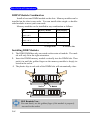
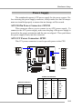
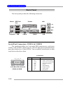
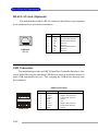
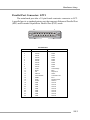
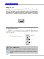
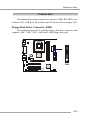
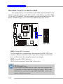
1
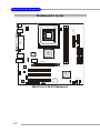
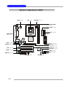
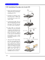
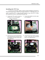
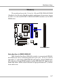
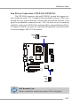
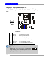
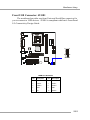
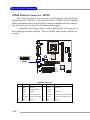
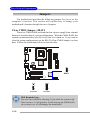
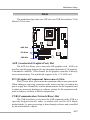
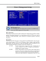
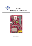
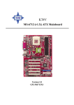
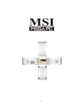
Getting Started Chapter 1. Getting Started Getting Started Thank you for purchasing the 648M-IL (MS-6703 v2.X) M-ATX mainboard. The MS-6703 v2.X mainboard is based on SiS® 648 B-step & 963 chipsets for optimal system efficiency. Designed to fit the advanced Intel® Pentium® 4 processors in the 478 pin package, the MS-6703 v2.X mainboard delivers a high performance and professional desktop platform solution. 1-1 MS-6703 M-ATX Mainboard Mainboard Specifications CPU h Supports Socket 478 for Intel Pentium 4/Celeron processors (Willamette, Northwood and Northwood with Hyper-threading) h Supports 400/533MHz CPU FSB h Supports Willamette and Northwood core frequency from 1.3 GHz to 2.8 GHz and up, Northwood with HT from 3.0 GHz and up Chipset h SiS® 648 B-step chipset - Supports Intel Pentium 4 processors with data transfer rate up to 533 MHz - Supports 64-bit high performance DDR333/DDR266 memory controller - Supports AGP 8X/4X interface - Supports Hyper Threading technology h SiS® 963 chipset - Supports Dual-IDE ATA 66/100/133 - Integrated audio controller with AC97 interface - Low pin count interface for SIO - Advanced power management and PC2001 compliance Main Memory h Supports two 184-pin DDR DIMMs h Supports up to 2GB PC2700/2100/1600 DDR SDRAMs h Supports 2.5v DDR SDRAM Slots h One AGP (Accelerated Graphics Port) 4x/8x slot. h Three 32-bit PCI bus slots (support 3.3v/5v PCI bus interface) On-BoardIDE h Dual-IDE controller integrated in SiS 963 chipset h Supports PIO, Bus Master and Ultra DMA133/100/66/33 operation modes h Can connect up to four IDE devices On-Board Peripherals h On-Board Peripherals include: - 1 floppy port supports 2 FDDs with 360K, 720K, 1.2M, 1.44M and 2.88Mbytes 1-2 Getting Started - 2 serial ports - 1 parallel port - 1 IrDA connector - 3 vertical audio ports - 6 USB ports (2 front and 4 rear) - 1 RJ-45 Lan Jack (optional) IEEE1394 h Realtek RTL8801B (can support up to 2 ports) Audio h Realtek ALC650 6-channel audio codec LAN (optional) h Realtek 8201B MII PHY BIOS h The mainboard BIOS provides “Plug & Play” BIOS which detects the peripheral devices and expansion cards of the board automatically. h The mainboard provides a Desktop Management Interface (DMI) function which records your mainboard specifications. Dimension h M-ATX Form Factor: 9.6” x 9.6” Mounting h 6 mounting holes Others h Suspend to RAM/Disk (S3/S4) h PC2001 compliant h Supports WOL (optional) 1-3 MS-6703 M-ATX Mainboard Mainboard Layout CPUFAN1 FDD 1 JPW1 Top : Parallel Port Bottom: COM A COM B Winbond W83697HF AGP Slot RTL 8801B DIMM 1 JSPD2 PCI Slot 1 IDE 2 J1394_1 DIMM 2 T: Line-In M:Line-Out B:Mic SiS 648 B-step BIOS Top: LAN Jack Bottom: USB ports IDE 1 T: 1394 port B: USB ports ATX Power Supply Top : mouse Bottom: keyboard RTL 8201BL PCI Slot 2 SiS 963 JCD1 JAUX1 PCI Slot 3 BATT + Codec CNR JAUD2 MS-6703 v2.X M-ATX Mainboard 1-4 JBAT1 JUSB1 JFP1 SYSFAN1 Hardware Setup Chapter 2. Hardware Setup Hardware Setup This chapter tells you how to install the CPU, memory modules, and expansion cards, as well as how to setup the jumpers on the mainboard. Also, it provides the instructions on connecting the peripheral devices, such as the mouse, keyboard, etc. While doing the installation, be careful in holding the components and follow the installation procedures. 2-1 MS-6703 M-ATX Mainboard Quick Components Guide JPW1, p.2-9 CPU, p.2-3 CPUFAN1, p.2-17 DDR DIMMs, p.2-7 CONN1, p.2-9 FDD1, p.2-15 Back Panel I/O, p.2-10 JSPD2, p.2-20 J1394_1, p.2-24 IDE1/2, p.2-16 AGP Slot, p.2-27 PCI Slots, p.2-27 JCD1, p.2-23 SYSFAN1, p.2-17 JAUX1, p.2-23 JUSB1, p.2-19 JFP1, p.2-22 CNR Slot, p.2-27 JAUD2, p.2-18 2-2 JBAT1, p.2-26 Hardware Setup Central Processing Unit: CPU The mainboard supports Intel® Pentium® 4 processor in the 478 pin package. The mainboard uses a CPU socket called PGA478 for easy CPU installation. When you are installing the CPU, make sure the CPU has a heat sink and a cooling fan attached on the top to prevent overheating. If you do not find the heat sink and cooling fan, contact your dealer to purchase and install them before turning on the computer. CPU Core Speed Derivation Procedure CPU Clock multiplied by Core/Bus ratio equals the CPU core speed. For example: If CPU Clock Core/Bus ratio then CPU core speed = = = = = 100MHz 14 Host Clock x Core/Bus ratio 100MHz x 14 1.4 GHz MSI Reminds You... Overheating Overheating will seriously damage the CPU and system, always make sure the cooling fan can work properly to protect the CPU from overheating. Replacing the CPU While replacing the CPU, always turn off the ATX power supply or unplug the power supply’s power cord from grounded outlet first to ensure the safety of CPU. Overclocking This motherboard is designed to support overclocking. However, please make sure your components are able to tolerate such abnormal setting, while doing overclocking. Any attempt to operate beyond product specifications is not recommended. We do not guarantee the damages or risks caused by inadequate operation or beyond product specifications. 2-3 MS-6703 M-ATX Mainboard CPU Installation Procedures for Socket 478 1. Please turn off the power and Open Lever unplug the power cord before installing the CPU. 2. Pull the lever sideways away Sliding Plate 90 degree from the socket. Make sure to raise the lever up to a 90degree angle. 3. Look for the cut edge. The cut edge should point towards the lever pivot. The CPU can only fit in the correct orientation. 4. If the CPU is correctly installed, the pins should be completely embedded into the socket and can not be seen. Please note that any violation of the correct installation procedures may cause permanent damages to your mainboard. Dot / Cut edge Correct CPU placement Dot / Cut edge Dot / Cut edge 2-4 X Incorrect CPU placement 5. Press the CPU down firmly into the socket and close the lever. As the CPU is likely to move while the lever is being closed, always close the lever with your fingers pressing tightly on top of the CPU to make sure the CPU is properly and completely embedded into the socket. O Press down the CPU Close Lever Hardware Setup Installing the CPU Fan As processor technology pushes to faster speeds and higher performance, thermal management becomes increasingly important. To dissipate heat, you need to attach the CPU cooling fan and heatsink on top of the CPU. Follow the instructions below to install the Heatsink/Fan: 1. Locate the CPU and its retention mechanism on the motherboard. 2. Position the heatsink onto the retention mechanism. retention mechanism 3. Mount the fan on top of the heatsink. 4. Press the two levers down to fasten Press down the fan until its four clips get wedged in the holes of the retention mechanism. the fan. Each lever can be pressed down in only ONE direction. levers 2-5 MS-6703 M-ATX Mainboard 5. Connect the fan power cable from the mounted fan to the 3-pin fan power connector on the board. fan power cable NOTES 2-6 Hardware Setup Memory The mainboard provides 2 slots for 184-pin DDR SDRAM DIMM (Double In-Line Memory Module) modules and supports the memory size up to 2GB. You can install DDR333/DDR266/DDR200 modules on the DDR DIMM slots. DDR DIMM Slots Introduction to DDR SDRAM DDR (Double Data Rate) SDRAM is similar to conventional SDRAM, but doubles the rate by transferring data twice per cycle. It uses 2.5 volts as opposed to 3.3 volts used in SDR SDRAM, and requires 184-pin DIMM modules rather than 168-pin DIMM modules used by SDR SDRAM. High memory bandwidth makes DDR an ideal solution for high performance PC, workstations and servers. 2-7 MS-6703 M-ATX Mainboard DIMM Module Combination Install at least one DIMM module on the slots. Memory modules can be installed on the slots in any order. You can install either single- or doublesided modules to meet your own needs. Memory modules can be installed in any combination as follows: Slot Memory Module Total Memory DIMM 1 (Bank 0 & 1) DIMM 2 (Bank 2 & 3) S/D 64MB~1GB S/D 64MB~1GB Maximum System Memory Supported 64MB~2GB S: Single Side D: Double Side Installing DDR Modules 1. The DDR DIMM has only one notch on the center of module. The module will only fit in the right orientation. 2. Insert the DIMM memory module vertically into the DIMM slot. Then push it in until the golden finger on the memory module is deeply inserted in the socket. 3. The plastic clip at each side of the DIMM slot will automatically close. Volt Notch MSI Reminds You... You can barely see the golden finger if the module is properly inserted in the socket. 2-8 Hardware Setup Power Supply The mainboard supports ATX power supply for the power system. Before inserting the power supply connector, always make sure that all components are installed properly to ensure that no damage will be caused. ATX 20-Pin Power Connector: CONN1 This connector allows you to connect to an ATX power supply. To connect to the ATX power supply, make sure the plug of the power supply is inserted in the proper orientation and the pins are aligned. Then push down the power supply firmly into the connector. ATX 12V Power Connector: JPW1 This 12V power connector is used to provide power to the CPU. 2 1 4 3 20 10 JPW1 1 11 CONN1 CONN1 Pin Definition JPW1 Pin Definition PIN SIGNAL 1 2 3 4 GND GND 12V 12V PIN SIGNAL PIN SIGNAL 1 2 3 4 5 6 7 8 9 3.3V 3.3V GND 5V GND 5V GND PW_OK 5V_SB 10 12V 11 12 13 14 15 16 17 18 19 20 3.3V -12V GND PS_ON GND GND GND -5V 5V 5V 2-9 MS-6703 M-ATX Mainboard Back Panel The back panel provides the following connectors: Mouse IEEE1394 Port Parallel LAN L-in L-out MIC COM A USB Keyboard COM B USB Serial Port Connectors: COM A & COM B The mainboard offers two 9-pin male DIN connectors as serial ports COM A and COM B. Both ports are 16550A high speed communication ports that send/receive 16 bytes FIFOs. You can attach a serial mouse or other serial device directly to them. Pin Definition 1 2 6 3 7 4 8 5 9 9-Pin Male DIN Connector COM A & COM B 2-10 PIN SIGNAL DESCRIPTION 1 2 3 4 5 6 7 8 9 DCD SIN SOUT DTR GND DSR RTS CTS RI Data Carry Detect Serial In or Receive Data Serial Out or Transmit Data Data Terminal Ready) Ground Data Set Ready Request To Send Clear To Send Ring Indicate Hardware Setup Mouse Connector The mainboard provides a standard PS/2® mouse mini DIN connector for attaching a PS/2® mouse. You can plug a PS/2® mouse directly into this connector. The connector location and pin assignments are as follows: Pin Definition 6 5 3 4 1 2 PS/2 Mouse (6-pin Female) PIN SIGNAL DESCRIPTION 1 2 3 4 5 6 Mouse DATA NC GND VCC Mouse Clock NC Mouse DATA No connection Ground +5V Mouse clock No connection Keyboard Connector The mainboard provides a standard PS/2® keyboard mini DIN connector for attaching a PS/2® keyboard. You can plug a PS/2® keyboard directly into this connector. Pin Definition 6 5 3 4 2 1 PS/2 Keyboard (6-pin Female) PIN SIGNAL DESCRIPTION 1 2 3 4 5 6 Keyboard DATA NC GND VCC Keyboard Clock NC Keyboard DATA No connection Ground +5V Keyboard clock No connection 2-11 MS-6703 M-ATX Mainboard RJ-45 LAN Jack (Optional) The mainboard provides a RJ-45 connector that allows your computer to be connected to a network environment. Pin 1 2 3 4 5 6 7 8 LAN Jack (RJ-45) Signal TDP TDN RDP NC NC RDN NC NC Description Transmit differential pair Transmit differential pair Receive differential pair Not used Not used Receive differential pair Not used Not used USB Connectors The mainboard provides an OHCI (Open Host Controller Interface) Universal Serial Bus root for attaching USB devices such as keyboard, mouse or other USB-compatible devices. You can plug the USB device directly into the connector. USB Port Description 1 2 3 4 5 6 7 8 USB Ports 2-12 PIN SIGNAL DESCRIPTION 1 2 3 4 5 6 7 8 VCC -Data 0 +Data0 GND VCC -Data 1 +Data 1 GND +5V Negative Data Channel 0 Positive Data Channel 0 Ground +5V Negative Data Channel 1 Positive Data Channel 1 Ground Hardware Setup Parallel Port Connector: LPT1 The mainboard provides a 25-pin female centronic connector as LPT. A parallel port is a standard printer port that supports Enhanced Parallel Port (EPP) and Extended Capabilities Parallel Port (ECP) mode. 13 1 14 25 Pin Definition PIN SIGNAL DESCRIPTION 1 2 3 4 5 6 7 8 9 10 11 12 13 14 15 16 17 18 19 20 21 22 23 24 25 STROBE DATA0 DATA1 DATA2 DATA3 DATA4 DATA5 DATA6 DATA7 ACK# BUSY PE SELECT AUTO FEED# ERR# INIT# SLIN# GND GND GND GND GND GND GND GND Strobe Data0 Data1 Data2 Data3 Data4 Data5 Data6 Data7 Acknowledge Busy Paper End Select Automatic Feed Error Initialize Printer Select In Ground Ground Ground Ground Ground Ground Ground Ground 2-13 MS-6703 M-ATX Mainboard IEEE1394 Port The mainboard provides one standard IEEE1394 port. The standard IEEE1394 port connects to IEEE1394 devices without external power. The IEEE1394 high-speed serial bus complements USB by providing enhanced PC connectivity for a wide range of devices, including consumer electronics audio/video (A/V) appliances, storage peripherals, other PCs, and portable devices. Audio Port Connectors Line Out is a connector for Speakers or Headphones. Line In is used for external CD player, Tape player, or other audio devices. Mic is a connector for microphones. 1/8” Stereo Audio Connectors Line In Line Out MIC MSI Reminds You... For advanced audio application, Realtek ALC650 audio chip is provided to offer support for 6-channel audio operation and can turn rear audio connectors from 2-channel to 4-/6-channel audio. 2-14 Hardware Setup Connectors The mainboard provides connectors to connect to FDD, IDE HDD, case, modem, LAN, USB Ports, IR module and CPU/System/Power Supply FAN. Floppy Disk Drive Connector: FDD1 The mainboard provides a standard floppy disk drive connector that supports 360K, 720K, 1.2M, 1.44M and 2.88M floppy disk types. FDD1 2-15 MS-6703 M-ATX Mainboard Hard Disk Connectors: IDE1 & IDE2 The mainboard has a 32-bit Enhanced PCI IDE and Ultra DMA 33/66/ 100/133 controller that provides PIO mode 0~4, Bus Master, and Ultra DMA 33/66/100/133 function. You can connect up to four hard disk drives, CDROM, 120MB Floppy (reserved for future BIOS) and other devices. IDE2 IDE1 IDE1 (Primary IDE Connector) The first hard drive should always be connected to IDE1. IDE1 can connect a Master and a Slave drive. You must configure second hard drive to Slave mode by setting the jumper accordingly. IDE2 (Secondary IDE Connector) IDE2 can also connect a Master and a Slave drive. MSI Reminds You... If you install two hard disks on cable, you must configure the second drive to Slave mode by setting its jumper. Refer to the hard disk documentation supplied by hard disk vendors for jumper setting instructions. 2-16 Hardware Setup Fan Power Connectors: CPUFAN1/SYSFAN1 The CPUFAN1 (processor fan) and SYSFAN1 (system fan) support system cooling fan with +12V. It supports three-pin head connector. When connecting the wire to the connectors, always take note that the red wire is the positive and should be connected to the +12V, the black wire is Ground and should be connected to GND. If the mainboard has a System Hardware Monitor chipset on-board, you must use a specially designed fan with speed sensor to take advantage of the CPU fan control. SENSOR +12V GND CPUFAN1 SENSOR +12V GND SYSFAN1 MSI Reminds You... Always consult the vendors for proper CPU cooling fan. 2-17 MS-6703 M-ATX Mainboard Front Panel Audio Connector: JAUD2 The front panel audio connector allows you to connect to the front panel audio. JAUD2 is compliant with Intel® Front Panel I/O Connectivity Design Guide. 10 2 1 9 JAUD2 Pin Definition PIN SIGNAL DESCRIPTION 1 2 3 4 5 6 7 8 9 10 AUD_MIC AUD_GND AUD_MIC_BIAS AUD_VCC AUD_FPOUT_R AUD_RET_R HP_ON KEY AUD_FPOUT_L AUD_RET_L Front panel microphone input signal Ground used by analog audio circuits Microphone power Filtered +5V used by analog audio circuits Right channel audio signal to front panel Right channel audio signal return from front panel Reserved for future use to control headphone amplifier No pin Left channel audio signal to front panel Left channel audio signal return from front panel MSI Reminds You... If you don’t want to connect to the front audio header, pins 5 & 6, 9 & 10 have to be jumpered in order to have signal output directed to the rear audio ports. Otherwise, the Line-Out connector on the back panel will not function. 2-18 6 10 5 9 Hardware Setup Front USB Connector: JUSB1 The mainboard provides one front Universal Serial Bus connector for you to connect to USB devices. JUSB1 is compliant with Intel® Front Panel I/O Connectivity Design Guide. 1 2 9 10 JUSB1 JUSB1 Pin Definition Pin Description Pin Description 1 USBPWR 2 USBPWR 3 USBP0- 4 USBP1- 5 USBP0+ 6 USBP1+ 7 GND 8 GND 9 NC 10 USBOC 2-19 MS-6703 M-ATX Mainboard SPDIF Bracket Connector: JSPD2 The connector allows you to connect a S-Bracket for Sony & Philips Digital Interface (SPDIF). The S-Bracket offers 2 SPDIF jacks for digital audio transmission (one for optical fiber connection and the other for coaxial), and 2 analog Line-Out jacks for 4-channel audio output. To attach the fiber-optic cable to optical SPDIF jack, you need to remove the plug from the jack first. The two SPDIF jacks support SPDIF output only. 12 11 2 1 JSPD2 JSPD2 Pin Definition 2-20 PIN SIGNAL DESCRIPTION PIN SIGNAL 1 VCC5 VCC 5V 2 VDD3 DESCRIPTION VDD 3.3V 3 SPDFO S/PDIF output 4 (No Pin) Key 5 GND Ground 6 SPDFI S/PDIF input 7 LFE-OUT Audio bass output 8 SOUT-R Audio right surrounding output 9 GET-OUT Audio center output 10 SOUT-L Audio left surrounding output 11 GND Ground GND Ground 12 Hardware Setup Connect to PORT 1 (IEEE) Connect to JSP2 SPDIF Bracket Rear R/L CEN/SUB SPDIFJack (optical) SPDIF Jack (coaxial) Connect to Center/ Port 1394 Subwoofer speakers Connect to Rear 2-channel output speakers 2-21 MS-6703 M-ATX Mainboard Front Panel Connector: JFP1 The mainboard provides one front panel connector for establishing electrical connection to the front panel switches and LEDs. JFP1 is compliant with Intel® Front Panel I/O Connectivity Design Guide. + 1 2 P HDD - S + + - RST 9 10 JFP1 JFP1 Switch/LED Front Panel Electrical Connection 2-22 PIN SIGNAL DESCRIPTION 1 2 3 4 5 6 7 8 9 HD_LED_P FP PWR/SLP HD_LED_N FP PWR/SLP RST_SW_N PWR_SW_P RST_SW_P PWR_SW_N RSVD_DNU Hard disk LED pull-up to +5V MSG LED pull-up to +5V Hard disk active LED MSG LED pull-up to +5V Reset Switch low reference pull-down to GND Power Switch high reference pull-up to +5V Reset Switch high reference pull-up to +5V Power Switch low reference pull-down to GND Reserved. Do not use. LED PWSW Hardware Setup CD-In Connector: JCD1 The connector is for CD-ROM audio connector. Aux Line-In Connector: JAUX1 The connector is for DVD add-on card with Line-in connector. R GND L L GND JAUX1 R JCD1 2-23 MS-6703 M-ATX Mainboard IEEE 1394 Connector: J1394_1 The mainboard provides one 1394 pin header that allows you to connect optional IEEE 1394 ports. 1 2 9 10 J1394_1 Pin Definition PIN SIGNAL 1 TPA+ PIN 2 SIGNAL TPA- 3 Ground 4 Ground 5 TPB+ 6 TPB- 7 Cable power 8 Cable power 9 Key (no pin) 10 Ground MSI Reminds You... The installation procedures shown here are for your reference only. For the actual position of the IEEE1394 connector, please refer to the mainboard. 2-24 Hardware Setup How to attach the IEEE 1394 Port: 1. Take out the IEEE 1394 Port. 2. Locate the IEEE 1394 connector(s) on the mainboard. 3. Insert the IEEE 1394 Port into the connector(s). 4. Place the IEEE 1394 Port into the first slot of your system case. 2-25 MS-6703 M-ATX Mainboard Jumpers The motherboard provides the following jumpers for you to set the computer’s function. This section will explain how to change your motherboard’s function through the use of jumpers. Clear CMOS Jumper: JBAT1 There is a CMOS RAM on board that has a power supply from external battery to keep the data of system configuration. With the CMOS RAM, the system can automatically boot OS every time it is turned on. If you want to clear the system configuration, use the JBAT1 (Clear CMOS Jumper ) to clear data. Follow the instructions below to clear the data: 1 JBAT1 3 1 Keep Data 3 1 Clear Data MSI Reminds You... You can clear CMOS by shorting 2-3 pin while the system is off. Then return to 1-2 pin position. Avoid clearing the CMOS while the system is on; it will damage the mainboard. 2-26 Hardware Setup Slots The motherboard provides one AGP slot, one CNR slot and three 32-bit Master PCI bus slots. AGP Slot PCI Slots CNR Slot AGP (Accelerated Graphics Port) Slot The AGP slot allows you to insert the AGP graphics card. AGP is an interface specification designed for the throughput demands of 3D graphics. It introduces a 66MHz, 32-bit channel for the graphics controller to directly access main memory. The mainboard supports 4x/8x 1.5V AGP card. PCI (Peripheral Component Interconnect) Slots The PCI slots allow you to insert the expansion cards to meet your needs. When adding or removing expansion cards, make sure that you unplug the power supply first. Meanwhile, read the documentation for the expansion card to make any necessary hardware or software settings for the expansion card, such as jumpers, switches or BIOS configuration. CNR (Communication Network Riser) Slot The CNR slot allows you to insert the CNR expansion cards. CNR is a specially designed network, audio, or modem riser card for ATX family motherboards. Its main processing is done through software and controlled by the motherboard’s chipset. 2-27 MS-6703 M-ATX Mainboard PCI Interrupt Request Routing The IRQ, abbreviation of interrupt request line and pronounced I-R-Q, are hardware lines over which devices can send interrupt signals to the microprocessor. The PCI IRQ pins are typically connected to the PCI bus INT A# ~ INT D# pins as follows: Order 1 Order 2 Order 3 Order 4 PCI Slot 1 INT B# INT C# INT D# INT A# PCI Slot 2 INT C# INT D# INT A# INT B# PCI Slot 3 INT D# INT A# INT B# INT C# 2-28 BIOS Setup Chapter 3. BIOS Setup BIOS Setup This chapter provides information on the BIOS Setup program and allows you to configure the system for optimum use. You may need to run the Setup program when: An error message appears on the screen during the system booting up, and requests you to run SETUP. You want to change the default settings for customized features. 3-1 MS-6703 M-ATX Mainboard Entering Setup Power on the computer and the system will start POST (Power On Self Test) process. When the message below appears on the screen, press <DEL> key to enter Setup. Press DEL to enter SETUP If the message disappears before you respond and you still wish to enter Setup, restart the system by turning it OFF and On or pressing the RESET button. You may also restart the system by simultaneously pressing <Ctrl>, <Alt>, and <Delete> keys. Control Keys <↑> Move to the previous item <↓> Move to the next item <←> Move to the item in the left hand <→> Move to the item in the right hand <Enter> Select the item <Esc> Jumps to the Exit menu or returns to the main menu from a submenu <+/PU> Increase the numeric value or make changes <-/PD> Decrease the numeric value or make changes <F1> General help, only for Status Page Setup Menu and Option Page Setup Menu <F5> Restore the previous CMOS value from CMOS, only for Option Page Setup Menu <F6> Load the default CMOS value from Fail-Safe default table, only for Option Page Setup Menu <F7> Load Optimized defaults <F10> Save all the CMOS changes and exit 3-2 BIOS Setup Getting Help After entering the Setup menu, the first menu you will see is the Main Menu. Main Menu The main menu lists the setup functions you can make changes to. You can use the control keys ( ↑↓ ) to select the item. The on-line description of the highlighted setup function is displayed at the bottom of the screen. Sub-Menu If you find a right pointer symbol (as shown in the right view) appears to the left of certain fields that means a sub-menu containing additional options can be launched from this field. You can use control keys ( ↑↓ ) to highlight the field and press <Enter> to call up the sub-menu. Then you can use the control keys to enter values and move from field to field within a sub-menu. If you want to return to the main menu, just press <Esc >. 8IDE 8IDE 8IDE 8IDE Primary Master Primary Slave Secondary Master Secondary Slave General Help <F1> The BIOS setup program provides a General Help screen. You can call up this screen from any menu by simply pressing <F1>. The Help screen lists the appropriate keys to use and the possible selections for the highlighted item. Press <Esc> to exit the Help screen. MSI Reminds You... The items under each BIOS category described in this chapter are under continuous update for better system performance. Therefore, the description may be slightly different from the latest BIOS and should be held for reference only. 3-3 MS-6703 M-ATX Mainboard The Main Menu Once you enter Award® BIOS CMOS Setup Utility, the Main Menu (Figure 1) will appear on the screen. The Main Menu allows you to select from twelve setup functions and two exit choices. Use arrow keys to select among the items and press <Enter> to accept or enter the sub-menu. Standard CMOS Features Use this menu for basic system configurations, such as time, date etc. Advanced BIOS Features Use this menu to setup the items of AWARD® special enhanced features. Advanced Chipset Features Use this menu to change the values in the chipset registers and optimize your system’s performance. Integrated Peripherals Use this menu to specify your settings for integrated peripherals. Power Management Setup Use this menu to specify your settings for power management. PNP/PCI Configurations This entry appears if your system supports PnP/PCI. 3-4 BIOS Setup PC Health Status This entry shows your PC health status. Frequency/Voltage Control Use this menu to specify your settings for frequency/voltage control. Load Fail-Safe Defaults Use this menu to load factory default settings into the BIOS for stable system performance operations. Load Optimized Defaults Use this menu to load the BIOS values for the best system performance, but the system stability may be affected. Set Supervisor Password Use this menu to set Supervisor Password. Set User Password Use this menu to set User Password. Save & Exit Setup Save changes to CMOS and exit setup. Exit Without Saving Abandon all changes and exit setup. 3-5 MS-6703 M-ATX Mainboard Standard CMOS Features The items in Standard CMOS Features Menu are divided into 11 categories. Each category includes no, one or more than one setup items. Use the arrow keys to highlight the item and then use the <PgUp> or <PgDn> keys to select the value you want in each item. Date This allows you to set the system to the date that you want (usually the current date). The format is <day><month> <date> <year>. day Day of the week, from Sun to Sat, determined by BIOS. Read-only. month The month from Jan. through Dec. date The date from 1 to 31 can be keyed by numeric function keys. year The year can be adjusted by users. Time This allows you to set the system time that you want (usually the current time). The time format is <hour> <minute> <second>. Primary/Secondary IDE Master/Slave Press PgUp/<+> or PgDn/<-> to select Manual, None or Auto type. Note that the specifications of your drive must match with the drive table. The hard disk will not work properly if you enter improper information for this category. 3-6 BIOS Setup If your hard disk drive type is not matched or listed, you can use Manual to define your own drive type manually. If you select Manual, related information is asked to be entered to the following items. Enter the information directly from the keyboard. This information should be provided in the documentation from your hard disk vendor or the system manufacturer. Access Mode The settings are CHS, LBA, Large, Auto. Capacity The formatted size of the storage device. Cylinder Number of cylinders. Head Number of heads. Precomp Write precompensation. Landing Zone Cylinder location of the landing zone. Sector Number of sectors. Floppy Drive A:/B: This item allows you to set the type of floppy drives installed. Available options: Not Installed, 1.2 MB 5¼, 720 KB 3½, 1.44 MB 3½ and 2.88 MB 3½. Floppy 3 Mode Support This item allows you to set the Floppy 3 Mode. Available options: Both, . Video The setting controls the type of video adapter used for the primary monitor of the system. Available options: EGA/VGA , CGA 40, CGA 80, MONO. Halt On The setting determines whether the system will stop if an error is detected at boot. Available options are: All Errors No Errors All, But Keyboard All, But Diskette All, But Disk/Key The system stops when any error is detected. The system doesn’t stop for any detected error. The system doesn’t stop for a keyboard error. The system doesn’t stop for a disk error. The system doesn’t stop for either a disk or a keyboard error. Base/Extended/Total Memory The three items show the memory status of your system (read only). 3-7 MS-6703 M-ATX Mainboard Advanced BIOS Features Quick Boot Setting the item to Enabled allows the system to boot within 5 seconds since it will skip some check items. Available options: Enabled, Disabled. Anti-Virus Protection The item is to set the Virus Warning feature for IDE Hard Disk boot sector protection. If the function is enabled and any attempt to write data into this area is made, BIOS will display a warning message on screen and beep. Settings: Disabled and Enabled. CPU L1 & L2 Cache The item allows you to turn on or off CPU’s internal (L1) and external (L2) cache. Settings: Enabled and Disabled. CPU L2 Cache ECC Checking This setting allows you to enable or disable the ECC (Error-Correcting Code) feature for error detection and correction when data passes through L2 cache memory. Setting options: Enabled, Disabled. 1st/2nd/3rd Boot Device The items allow you to set the sequence of boot devices where BIOS attempts to load the disk operating system. The settings are: 3-8 BIOS Setup Floppy LS120 HDD-0 SCSI CDROM HDD-1 HDD-2 HDD-3 ZIP100 USB-FDD The system will boot from floppy drive. The system will boot from LS-120 drive. The system will boot from the first HDD. The system will boot from the SCSI. The system will boot from the CD-ROM. The system will boot from the second HDD. The system will boot from the third HDD. The system will boot from the fourth HDD. The system will boot from ATAPI ZIP drive. The system will boot from USB-interfaced floppy drive. USB-ZIP The system will boot from any USB-interfaced ATAPI ZIP drive USB-CDROM The system will boot from the USB-interfaced CD-ROM. USB-HDD The system will boot from the USB-interfaced HDD. LAN The system will boot from the Network drive. Disabled Disable this sequence. MSI Reminds You... Available settings for “1st/2nd/3rd Boot Device” vary depending on the bootable devices you have installed. For example, if you did not install a floppy drive, the setting “Floppy” does not show up. Boot Other Device Setting the option to Enabled allows the system to try to boot from other device if the system fails to boot from the 1st/2nd/3rd boot device. Swap Floppy Setting to Enabled will swap floppy drives A: and B:. Seek Floppy Setting to Enabled will make BIOS seek floppy drive A: before booting the system. Settings: Disabled, Enabled. Boot Up NumLock Status This setting is to set the Num Lock status when the system is powered on. Setting to On will turn on the Num Lock key when the system is powered on. Setting to Off will allow users to use the arrow keys on the numeric keypad. Setting options: On, Off. 3-9 MS-6703 M-ATX Mainboard Gate A20 Option This item is to set the Gate A20 status. A20 refers to the first 64KB of extended memory. When the default value Fast is selected, the Gate A20 is controlled by Port92 or chipset specific method resulting in faster system performance. When Normal is selected, A20 is controlled by a keyboard controller or chipset hardware. Typematic Rate Setting This item is used to enable or disable the typematic rate setting including Typematic Rate & Typematic Delay. Typematic Rate (Chars/Sec) After Typematic Rate Setting is enabled, this item allows you to set the rate (characters/second) at which the keys are accelerated. Settings: 6, 8, 10, 12, 15, 20, 24 and 30. Typematic Delay (Msec) This item allows you to select the delay between when the key was first pressed and when the acceleration begins. Settings: 250, 500, 750 and 1000. Security Option This specifies the type of BIOS password protection that is implemented. Settings are described below: Option Setup Description The password prompt appears only when end users try to run Setup. System A password prompt appears every time when the computer is powered on or when end users try to run Setup. HDD S.M.A.R.T. Capability This allows you to activate the S.M.A.R.T. (Self-Monitoring Analysis & Reporting Technology) capability for the hard disks. S.M.A.R.T is a utility that monitors your disk status to predict hard disk failure. This gives you an opportunity to move data from a hard disk that is going to fail to a safe place before the hard disk becomes offline. Settings: Enabled and Disabled. 3-10 BIOS Setup HT CPU Function The Intel processor uses Hyper-Threading technology to increase transaction rates and reduces end-user response times. The technology treats the two cores inside the processor as two logical processors that can execute instructions simultaneously. In this way, the system performance is highly improved. If you disable the function, the processor will use only one core to execute the instructions. Settings: Enabled, Disabled. MSI Reminds You... Enabling the functionality of Hyper-Threading Technology for your computer system requires ALL of the following platform Components: *CPU: An Intel® Pentium® 4 Processor with HT Technology; *Chipset: An Intel® Chipset that supports HT Technology; *BIOS: A BIOS that supports HT Technology and has it enabled; and *OS: An operating system that supports HT Technology. For more information on Hyper-threading Technology, go to: www.intel.com/info/hyperthreading APIC Mode This field is used to enable or disable the APIC (Advanced Programmable Interrupt Controller). Due to compliance with PC2001 design guide, the system is able to run in APIC mode. Enabling APIC mode will expand available IRQ resources for the system. Settings: Enabled and Disabled. MPS Table Version This field allows you to select which MPS (Multi-Processor Specification) version to be used for the operating system. You need to select the MPS version supported by your operating system. To find out which version to use, consult the vendor of your operating system. Settings: 1.4, 1.1. 3-11 MS-6703 M-ATX Mainboard Advanced Chipset Features MSI Reminds You... Change these settings only if you are familiar with the chipset. DRAM Clock/Timing Control Press <Enter> and the following sub-menu appears. Current CPU/DRAM/DDR Frequency It shows the current CPU/DRAM/DDR frequency. (read only) DRAM Frequency This item is used to configure the clock frequency of the installed DRAM. Settings: By SPD, 100MHz, 133MHz, 166MHz, 200MHz. DRAM Timing Control Selects whether DRAM timing is controlled by the SPD (Serial Presence Detect) EEPROM on the DRAM module. Setting to By SPD enables 3-12 BIOS Setup DRAM timings to be determined by BIOS based on the configurations on the SPD. Selecting Manual allows users to configure the DRAM timings manually. DRAM CAS Latency This controls the timing delay (in clock cycles) before SDRAM starts a read command after receiving it. Settings are: 2T, 2.5T, 3T. 2T increases the system performance while 3T provides the most stable performance. RAS Active Time (tRAS) This setting controls the number of clock cycles for DRAM to be allowed to precharge from the active state. Settings: 4,T, 5T, 6T, 7T, 8T, 9T. RAS Precharge Time (tRP) This item controls the number of cycles for Row Address Strobe (RAS) to be allowed to precharge. If insufficient time is allowed for the RAS to accumulate its charge before DRAM refresh, refresh may be incomplete and DRAM may fail to retain data. This item applies only when synchronous DRAM is installed in the system. Available settings: 2T, 3T, 4T, 5T. RAS to CAS Delay (tRCD) When DRAM is refreshed, both rows and columns are addressed separately. This setup item allows you to determine the timing of the transition from RAS (row address strobe) to CAS (column address strobe). The less the clock cycles, the faster the DRAM performance. Setting options: 2T, 3T, 4T, 5T. MA 1T/2T Select This setting controls the SDRAM command rate. Selecting 1T allows SDRAM signal controller to run at 1T (T=clock cycles) rate. Selecting 2T makes SDRAM signal controller run at 2T rate. 1T is faster than 2T. Setting options: Auto, 1T, 2T. AGP & P2P Bridge Control Press <Enter> and the following sub-menu appears. 3-13 MS-6703 M-ATX Mainboard AGP Aperture Size This setting controls just how much system RAM can be allocated to AGP for video purposes. The aperture is a portion of the PCI memory address range dedicated to graphics memory address space. Host cycles that hit the aperture range are forwarded to the AGP without any translation. The option allows the selection of an aperture size of 4MB, 8MB, 16MB, 32MB, 64MB, 128MB, and 256 MB. 3-14 BIOS Setup Integrated Peripherals SIS OnChip IDE Device Press <Enter> to enter the sub-menu and the following screen appears: Internal PCI/IDE This setting enables or disables the internal primary and secondary PCI & IDE controllers. Setting options: Disabled, Primary, Secondary, Both. IDE Primary/Secondary Master/Slave PIO The four IDE PIO (Programmed Input/Output) fields let you set a PIO mode (0-4) for each of the four IDE devices that the onboard IDE interface supports. Modes 0 through 4 provide successively increased performance. In Auto mode, the system automatically determines the best mode for each device. The settings are: Auto, Mode 0, Mode 1, Mode 2, Mode 3, Mode 4. 3-15 MS-6703 M-ATX Mainboard Primary/Secondary Master/Slave UltraDMA Ultra DMA/33 implementation is possible only if your IDE hard drive supports it and the operating environment includes a DMA driver (Windows 95 OSR2 or a third-party IDE bus master driver). If your hard drive and your system software both support Ultra DMA/33, Ultra DMA/ 66 and Ultra DMA/100 select Auto to enable BIOS support. The settings are: Auto, Disabled. IDE DMA Transfer Access This item allows users to enable or disable the DMA transfer function of the IDE hard drive. The settings are: Enabled, Disabled. SIS OnChip PCI Device Press <Enter> to enter the sub-menu and the following screen appears: SIS USB Controller This setting is used to enable/disable the onboard USB controller. Setting options: Disabled, Enabled. USB 2.0 Supports Set to Enabled if you need to use any USB 2.0 device in the operating system that does not support or have any USB 2.0 driver installed, such as DOS and SCO Unix. Setting options: Disabled, Enabled. SIS Keyboard Support Select Enabled if you need to use a keyboard in the operating system. Setting options: Enabled, Disabled. SIS Mouse Support Select Enabled if you need to use a mouse in the operating system. Setting options: Enabled, Disabled. SIS AC97 AUDIO Auto allows the motherboard’s BIOS to detect whether you’re using any 3-16 BIOS Setup audio device. If so, the onboard audio controller will be enabled. If not, the onboard audio controller will be disabled. If you want to use different controller cards to connect audio connectors, set the field to Disabled. Setting options: Disabled, Auto. SIS S/W Modem Auto allows the mainboard to detect whether a modem is used. If a modem is detected, the onboard S/W modem controller will be enabled; if not, it is disabled. Disable the controller if you want to use other controller cards to connect a modem. Settings: Auto, Disabled. SIS 1394 Controller This item allows you to enable/disable the onboard IEEE1394 controller. Setting options: Enabled and Disabled. SIS 10/100M ETHERNET The field determines whether the onboard LAN controller is activated. Setting options: Enabled, Disabled. Onboard Lan Boot ROM The items enable or disable the initialization of the onboard LAN Boot ROM during bootup. Selecting Disabled will speed up the boot process. Onboard Super IO Device Press <Enter> to enter the sub-menu and the following screen appears: Onboard FDC Controller Select Enabled if your system has a floppy disk controller (FDD) installed on the system board and you wish to use it. If you install add-on FDC or the system has no floppy drive, select Disabled in this field. The settings are: Enabled and Disabled. Onboard Serial Port 1/Port 2 Select an address and corresponding interrupt for the first and second 3-17 MS-6703 M-ATX Mainboard serial ports. The settings are: 3F8/IRQ4, 2E8/IRQ3, 3E8/IRQ4, 2F8/IRQ3, Disabled, Auto. Onboard Parallel Port There is a built-in parallel port on the on-board Super I/O chipset that provides Standard, ECP, and EPP features. It has the following options: Disabled 3BC/IRQ7 Line Printer port 0 278/IRQ5 Line Printer port 2 378/IRQ7 Line Printer port 1 Parallel Port Mode SPP : Standard Parallel Port EPP : Enhanced Parallel Port ECP : Extended Capability Port ECP + EPP: Extended Capability Port + Enhanced Parallel Port To operate the onboard parallel port as Standard Parallel Port only, choose “SPP.” To operate the onboard parallel port in the EPP mode simultaneously, choose “EPP.” By choosing “ECP”, the onboard parallel port will operate in ECP mode only. Choosing “ECP + EPP” will allow the onboard parallel port to support both the ECP and EPP modes simultaneously. EPP Mode Select The onboard parallel port is EPP Spec. compliant, so after the user chooses the onboard parallel port with the EPP function, the following message will be displayed on the screen: “EPP Mode Select.” At this time either EPP 1.7 spec or EPP 1.9 spec can be chosen. ECP Mode Use DMA The ECP mode has to use the DMA channel, so choose the onboard parallel port with the ECP feature. After selecting it, the following message will appear: “ECP Mode Use DMA.” At this time, the user can choose between DMA channel 3 or 1. Init Display First This item specifies which VGA card is your primary graphics adapter. Settings: PCI Slot and AGP. 3-18 BIOS Setup Power Management Setup MSI Reminds You... S3-related functions described in this section are available only when your BIOS supports S3 sleep mode. IPCA Function This item is to activate the ACPI (Advanced Configuration and Power Management Interface) function. If your operating system is ACPI-aware, such as Windows 98SE/2000/ME, select Enabled. Available options: Enabled, Disabled. Sleep State This item specifies the power saving modes for ACPI function. If your operating system supports ACPI, such as Windows 98SE, Windows ME and Windows 2000, you can choose to enter the Standby mode in S1(POS) or S3 (STR) fashion through the setting of this field. Options are: S1/POS The S1 sleep mode is a low power state. In this state, no system context is lost (CPU or chipset) and hardware maintains all system context. S3/STR The S3 sleep mode is a lower power state where the in formation of system configuration and open applications/ files is saved to main memory that remains powered while most other hardware components turn off to save 3-19 MS-6703 M-ATX Mainboard energy. The information stored in memory will be used to restore the system when a “wake up” event occurs. Power Management This item is used to select the degree (or type) of power saving and is related to these modes: Suspend Mode and HDD Power Down. There are three options for power management: Min Saving Minimum Power Management. Suspend Mode=1 Hour Max Saving Maximum Power Management. Suspend Mode=1 Min User Define Allows end users to configure each mode separately. Suspend Mode After the selected period of system inactivity, all devices except the CPU shut off. Settings: Disabled, 1Min, 2Min, 4Min, 8Min, 12Min, 20Min, 30Min, 40Min, 1 Hour. MODEM Use IRQ This determines the IRQ in which the MODEM can use. Activity of the selected IRQ always awakens the system. Settings: 3, 4, 5, 7, 9, 10, 11, NA.. Hot Key Function As This setting specifies the function of the preset hot key. Settings: Disabled, Power Off, Suspend. HDD Off After If enabled and after the set time of system inactivity, the hard disk drive will be powered down while all other devices remian active. Settings: Disabled, 1 Min ~ 15Min. Power Button Function This feature sets the function of the power button. Settings are: Power Off The power button functions as normal power off button. Suspend When you press the power button, the computer enters the suspend/sleep mode, but if the button is pressed for more than four seconds, the computer is turned off. After AC Power Lost This setting specifies whether your system will reboot after a power failure or 3-20 BIOS Setup interrupt occurs. Available settings are: Power Off Leaves the computer in the power off state. Power On Reboots the computer. Last State Restores the system to the previous status before power failure or interrupt occurred. PM Wake Up Events Press <Enter> and the following sub-menu appears. IRQ [3-7, 9-15], NMI & IRQ 8 Break Suspend This setting enables/disables the monitoring of the specified IRQ line. If set to Enabled, the activity of the specified IRQ line will prevent the system from entering power saving modes or awaken it from power saving modes. Setting options: Disabled, Enabled. MSI Reminds You... IRQ (Interrupt Request) lines are system resources allocated to I/ O devices. When an I/O device needs to gain attention of the operating system, it signals this by causing an IRQ to occur. After receiving the signal, when the operating system is ready, the system will interrupt itself and perform the service required by the I/O device. MACPME Power Up Control This item is used to activate the south bridge LAN controller. When set to Enabled, any signal from the LAN controller will awaken the system from power saving modes. Settings are: Enabled and Disabled. 3-21 MS-6703 M-ATX Mainboard Wake Up On PME When set to Enabled, the feature allows your system to be awakened from the power saving modes through any event on PME (Power Management Event). Settings are: Enabled and Disabled. USB Wake Up from S3 This item allows the activity of the USB device to wake up the system from S3 (Suspend to RAM) sleep state. Settings are: Enabled and Disabled. PS2KB Wake Up from S3/S4/S5 This setting allows you to enter “Any Key” (max. 8 numbers) to wake up the system from S3/S4/S5 state. Settings are: Hot Key and Disabled. PS2MS Wake Up from S3/S4/S5 This setting allows the activity of the mouse to wake up the system from S3/S4/S5 state. Settings are: Enabled and Disabled. MSI Reminds You... If you have enabled the“PS2MS Wake Up from S3/S4/S5” function, you need to click the mouse to power on the system. Resume By Alarm This function is for setting date and time for your computer to boot up. During Disabled, you cannot use this function. During Enabled, choose the Month, Day, and Time Alarm: Month Alarm You can choose which month the system will boot up. Day of Month Alarm You can choose which day of the preset month the system will boot up. Set to 0, to boot every day. Time (hh:mm:ss) Alarm You can choose what hour, minute and second the system will boot up. MSI Reminds You... If you have changed this setting, you must let the system boot up until it enters the operating system, before this function will work. 3-22 BIOS Setup **Reload Global Timer Events** Primary/Secondary IDE 0/1, FDD, COM, LPT Port, PCI PIRQ [AD] # The global timer is the hardware timer that counts down to the power saving modes. If the monitoring of the listed hardware peripherals or components is enabled, the activity of the specified peripherals or components will awaken the system or reload the original count of global timer when they are accessed. 3-23 MS-6703 M-ATX Mainboard PNP/PCI Configurations This section describes configuring the PCI bus system and PnP (Plug & Play) feature. PCI, or Peripheral Component Interconnect, is a system which allows I/O devices to operate at speeds nearing the speed the CPU itself uses when communicating with its special components. This section covers some very technical items and it is strongly recommended that only experienced users should make any changes to the default settings. Clear ESCD Normally, you leave this field Disabled. Select Enabled to reset Extended System Configuration Data (ESCD) when you exit Setup if you have installed a new add-on and the system reconfiguration has caused such a serious conflict that the operating system can not boot. The settings are: Enabled and Disabled. Resource Controlled By The Award Plug and Play BIOS has the capacity to automatically configure all of the boot and Plug and Play compatible devices. However, this capability means absolutely nothing unless you are using a Plug and Play operating system such as Windows® 95/98. If you set this field to “manual” choose specific resources by going into each of the sub menu that follows this field (a sub menu is preceded by a “¾”). The settings are: Auto (ESCD), Manual. 3-24 BIOS Setup IRQ Resources The items are adjustable only when Resources Controlled By is set to Manual. Press <Enter> and you will enter the sub-menu of the items. IRQ Resources list IRQ 3/4/5/7/9/10/11/12/14/15 for users to set each IRQ a type depending on the type of device using the IRQ. Settings are: PCI Device For Plug & Play compatible devices designed for PCI bus architecture. Reserved The IRQ will be reserved for further request. PCI/VGA Palette Snoop When set to Enabled, multiple VGA devices operating on different buses can handle data from the CPU on each set of palette registers on every video device. Bit 5 of the command register in the PCI device configuration space is the VGA Palette Snoop bit (0 is disabled). For example, if there are two VGA devices in the computer (one PCI and one ISA) and the: VGA Palette Snoop Bit Setting Action Disabled Data read or written by the CPU is only directed to the PCI VGA device’s palette registers. Enabled Data read or written by the CPU is directed to both the PCI VGA device’s palette registers and the ISA VGA device’s palette registers, permitting the palette registers of both VGA devices to be identical. The setting must be set to Enabled if any ISA bus adapter in the system requires VGA palette snooping. 3-25 MS-6703 M-ATX Mainboard PC Health Status This section shows the status of your CPU, fan, overall system status, etc. Monitor function is available only if there is hardware monitoring mechanism onboard. CPU Warning Temperature This item is used to specify a thermal limit for CPU. If CPU temperature reaches the specified limit, the system will issue a warning which allows you to prevent the CPU overheat problem. Settings: Disabled, 50oC/122oF, 53oC/ 127oF, 56oC/133oF, 60oC/140oF, 63oC/145oF, 66oC/151oF and 70oC/158oF. System/CPU Temperature, System/CPU FAN Speed, Vcore, 3.3V, +5V, +12V, -12V, VBAT(V), 5VSB(V) These items display the current status of all of the monitored hardware devices/components such as CPU voltages, temperatures and all fans’ speeds. Shutdown Temperature When the processor reaches the preset temperature, the ACPI-aware system will be shut down. Settings: Disabled, 60oC/140oF, 65oC/149oF, 70oC/158oF, 75oC/167oF. 3-26 BIOS Setup Frequency/Voltage Control Use this menu to specify your settings for frequency/voltage control. CPU Clock Ratio This setting controls the multiplier that is used to determine the internal clock speed of the processor relative to the external or motherboard clock speed. Auto Detect DIMM/PCI Clk This option allows you to enable/disable the feature of auto detecting the clock frequency of the installed DIMM/PCI bus. The settings are: Enabled, Disabled. Spread Spectrum When the motherboard’s clock generator pulses, the extreme values (spikes) of the pulses creates EMI (Electromagnetic Interference). The Spread Spectrum function reduces the EMI generated by modulating the pulses so that the spikes of the pulses are reduced to flatter curves. If you do not have any EMI problem, leave the setting at Disabled for optimal system stability and performance. But if you are plagued by EMI, activate the Spread Spectrum for EMI reduction. Remember to disable Spread Spectrum if you are overclocking because even a slight jitter can introduce a temporary boost in clockspeed which may just cause your overclocked processor to lock up. Options: Disabled, +/-0.25%, +/-0.30%, +/-0.35%, +/-0.40%. CPU Frequency Use this item to select the appropriate frequency for your CPU FSB. Options are: Default, 100MHz, 133MHz. 3-27 MS-6703 M-ATX Mainboard Load Fail-Safe/Optimized Defaults The two options on the main menu allow users to restore all of the BIOS settings to the default Fail-Safe or Optimized values. The Optimized Defaults are the default values set by the mainboard manufacturer specifically for optimal performance of the mainboard. The Fail-Safe Defaults are the default values set by the BIOS vendor for stable system performance. When you select Load Fail-Safe Defaults, a message as below appears: Pressing Y loads the BIOS default values for the most stable, minimal system performance. When you select Load Optimized Defaults, a message as below appears: Pressing Y loads the default factory settings for optimal system performance. 3-28 BIOS Setup Set Supervisor/User Password When you select this function, a message as below will appear on the screen: Type the password, up to eight characters in length, and press <Enter>. The password typed now will replace any previously set password from CMOS memory. You will be prompted to confirm the password. Retype the password and press <Enter>. You may also press <Esc> to abort the selection and not enter a password. To clear a set password, just press <Enter> when you are prompted to enter the password. A message will show up confirming the password will be disabled. Once the password is disabled, the system will boot and you can enter Setup without entering any password. When a password has been set, you will be prompted to enter it every time you try to enter Setup. This prevents an unauthorized person from changing any part of your system configuration. Additionally, when a password is enabled, you can also have BIOS to request a password each time the system is booted. This would prevent unauthorized use of your computer. The setting to determine when the password prompt is required is the Security Option of the Advanced BIOS Feature menu. If the Security Option is set to System, the password is required both at boot and at entry to Setup. If set to Setup, password prompt only occurs when you try to enter Setup. MSI Reminds You... About Supervisor Password & User Password: Supervisor password: Can enter and change the settings of the setup menu. User password: Can only enter but do not have the right to change the settings of the setup menu. 3-29