1
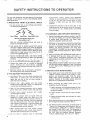
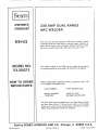
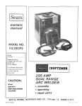
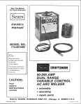
MODEL N_ °
113.201372 _
Serial
Number
Model and serial
number may be found
at the rear
of the cabinet.
You should record both
model and serial number
in a safe place for
future use,
230 AMP
DUAL RANGE
ARC WELDER
CAUTION:
Read
® assembly
SAFETY
UNSTRUCTIONS
e operating
carefully
® repair parts
Sold by SEARS,
Part No. 61337
ROEBUCK
AND
CO., Chicago,
IL 60684
U.S.A.
Printed in U S A
SAFETY gNSTRUCTIONS
TO OPERATOR
For your own protection, read and observe all instructions
included in this manual as well as the following specific
safety precautions:
1, PROTECTION
FROM
ELECTRICAL
hydrocarbon
vapors
coming
from
degreasing,
cleaning, or spraying operations
The heat of the rays
of the arc can react with
solvent
vapors to form
phosgene,
a highly
toxic
gas, and other
irritating
products
SHOCK
a_ Do not let bare skin or wet clothing come between
the following combinations:
h
Electrode
Unprotected
spectators
must be kept clear of the
welding area due to the harmful
nature of ultra÷violet
and infra-red
arc rays, welding sparks, and welding
fumes and gases
3. FLAMMABLE
Work Clamp
Work Piece
Metal Work 'Table
a
80 volts exist between these parts
when welder is onH!
Wear dry hole-free, clothing,_ gloves and shoes to
protect and insulate the body.
b. Take special care to insulate" yourself from ground
using dry insulation (suchas dry wood) of-ad.equate
size when welding] in dam'p locations on metal floors
or grat ngs, and m poslt_ons (such as s=ttmg or lying ! "
where parts-or"large"areas of your body can be ir
contact with phssible ground_. ; ".;_
r o "_
C. Maintain the_.#l_ctr_de h_tder work clamp, w_ldin'g
cable and welding_:rnach_ne'._n _Qd, safe operating._
condition,
: _ _;
" " ,:'
-'
•
"
Do not use weldm_ electrode as-a claarette hg_ter, .
-
e. Connect the welder only to a source of electncal'.power
meeting
the
requirements,
irrcluding
grounding, of the National Electrical Code (ANSI Cl)
and local codes.
f.
Electrode coating may be electrically conductiveuse welding gloves when changing electrodes.
a.
b
Remove flammable and explosive material at least 35
feet from the welding arc to prevent welding sparks
or molten metal from starting a fire Keep a type
ABC fire extinguisher within easy reach.
iild Never-c_nnect the_work cablelor clamp to any obJect
b_ _'he 'worl<:p e_e o_ me.to _ork tab e Conr]ecting
to other objects such as bu_l_mg ground can create a
fire hazard.
4. PREVENTATIVE
b.
MAINTENANCE
Never apply power to the welder with any part of the
"cabinet" removed_ Position on-off switch in "Off"
position
and disconnect welder from the power
supply before doing maintenance work inside the
machine. Removal of the welder cabinet should be
done only by a qualified service technician,
Before connecting the welder
receptacle, check the following:
power
cord
to
the
c. Wear oil free protective garments, such as leather
gloves, heavy shirt, cuffless trousers and high shoes.
1 Inspect the power cord and welding cables for cuts
or burns and make sure blades and ground pin on
the plug are straighL
d
Protect
other
near-by
non-flammable
screening_
2
Inspect
parts.
e
Welding
can produce
fumes
and gases which
are
dangerous
to health,
Keep your
head out of the
fumes, Use enough ventilation,
exhaust at the arc, or
both, to keep fumes and gases from your breathing
zone and the general
area, Take even greater care
when welding on galvanized
or cadmium
plated steel
and
other
metals
which
produce
toxic
fumes
Ab-supplied
helmets may be necessary
3
Inspect electrode
or broken parts.
f
g
2
MATERIALS
c. When not welding, place the electrode holder where it
"" i_ ihs'61ated from the work clamp, work piece, or'
wc_rk 'table_._ Ac_'idental
grounding can cause
,_ overheating of the_ables'and_welder,
creating a fire
haz_rd_ _ ::_"
_
"
Use helmet, filter, and cover plate complying with
ANSI Z87 1 to protect your eyes and face from
sparks and the rays of the arc when welding or
observing open arc welding,
Always
wear
safety goggles with side shields
complying with ANSI Z871 when in a welding area,
or when near slag chipping operation
EXPLOSIVE
b, Welding on or near containers which hold combustibles
can cause ar_ explosion, even when they have been
cleaned= For information purchase "Safe Practices for
Welding one Cutting Containers that Have Hel d
Combustibles" (A6.0-65_ from the American Welding
:.Society 2501 Northwest Seventh St Miami, Florida
a.
2. EYE AND BODY PROTECTION
AND
personnel
with
When working
above
floor
level, protect
from a fall should you get a shock Never
electrode
cable
Do
weld
not
around
in
arty part of your
locations
close
to
suitable
yourself
wrap the
body
chlorinated
c.
"On-Off"
switch
lever for cracks or broken
holder jaw insulators for cracks
Never weld anything on or to the welder cabinet, as a
burn through may cause transformer failure.
d_ For additional safety information, purchase copies of
"Practice for Occupational and Educational Eye and
Face Protection"
(ANSI Z87.1), "Safety in Welding
and Cutting" (ANSI Z49.1), and "Fire Protection in
Use of Welding and Cutting Processes" (ANSI/NFPA
No. 518) from the American National Standards
institute, 1430 Sroadway, New York, N.Y 10018_
READANDOBSERVE
THEINSTRUCTIONS
APPEARING
ONTHEWARNING
LABELSFOUNDONTHEINSIDE
OF
THEWELDING
HELMET,
ANDONTHESELECTOR
PLATE,
CABINET
ANDELECTRODE
HOLDER.
_MERIEAN
WARNII_G:
N,_ 71ON,_L ST,INI,),_RDS
PttEC,_UTION_RY
I Af]EL
prolel:I
VotJt_ell
_t_d
unders14_mt lh_ I_bel
F UJ%_ES AND
GASES
ARC
RAYS call inlllle
SHOCK
cml kill
• Be,_d and understand
and yo_Jt amployef's
hV_TITUTE
WARNING
{_thefs
_e;l(I
;_f_{I
c;lll he (i,ln{J_ f al_s tn ymJl he_hh
eyel and hum stroll ELECTRIC
_l_e incm_Hanh_fef
_alely
_ =nslnJ_io_t_
pr acllce_
_ar _nd body
salely spectacles)
shou+d be worn
wheII U_l_ 0 this device It_cl fesislanl plal_
ale DOT un_le.lkable
elted ¢_ s_la_h_d _Je_ t_u_ VISI_I
al_{_ 5_liO_$1 le_uc8
pI01eGIJ0r_-{epia_eintricately
ltlo_ectlon
• Do I_O_ _ouch llve elec_ rical I)aFt_
• See American
National
Si,_nIt,_f(I
Z49.1
S_lety
in
Wl!h_hlg
mid Cliilin=j ¸' i)_JIilillle(I
I}7 lhe Ait/eficalt
Wohthlg
Sociel¥
2501
N W 71h SI,, _,tbm_
Florida
33125;
OSIIA
Saf_W _1_{I He_hh
SI,_ndatds
29 CFR
1910,
availal)_J_
hont
U S
Dep_tmenl
o_ Labor
Washinglon
, DC 20210
DO NOT R E_,_OV E THIS LABEL
WARNING
ELeCTR,C
SHOCK
CAN
BE FATALt
FOR YOUR SAFET'_
B0 VOLT POTENTIAL
AT ELECT}IOD_
USe _lJ
101 IE,_ _n0 _y_ pi01egi0n
a_ins$ =nj_io_ rays Itom _c _ding
_nd culling
US_ propel shade li!I_
plale _P¢_.I {ssi_IO _12 plo[_ction
(Iil_ pble b_ck_up plale• s_p_lale
• Keep your head aut of _1_ h_nles
• U_a enmJ_h Vel_il_iOl_,
_xha_Jst al Ihe ;_,c, ot boUI
lo kee I) _ume_ and _ase_ from
7o_f
I_re;_lhi_ I z_)m_
and the {Jene[al area
• Wear cot _ecl eye,
-
R_GAR_ING
SHOC;{
CllRI0_
REGARDING
POTENTIAL
SHOCK
COW,FORMING TO 1H_ _ATIONAL
REGAROING
Inspecl
{(equ_Ily an_ immedi31_ly
I_p_u_ _om ot d_m_ged p_tls
t,it4_ ir_ t¢=¢.¢_
=f JJ.I.L
zr/1
DO NOT REMOVE "fills [/_3,E L
£yE
REGARDING
LI_
ON
CABINET
_L_CTnlCAL
COD_
INJURY
FIRE
O_AW
_*nC eT_muY't
LENS
SHADENO
BEFORE
TURNING
WELDER
ON
CHECK
THE ELECTRODE
HOLDER
TO
BE SURE THAT
THERE
ARE NO PROTRUDING
SCREW
HEADS
AND
THAT
ALL INSULATION
IS SECURE
_ _ll!!
2
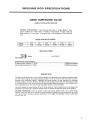
FULL ONE YEAR WARRANTY
If this Craftsman
within
ON CRAFTSMAN
Electric Welder fails to perform
one year from
the date of purchase,
Sears will
ELECTRIC
WELDER
properly, due to a defect in material or workmanship,
repair it free of charge,
WARRANTY
SERVICE IS AVAILABLE
BY SIMPLY RETURNING
THE WELDER
SEARS STORE OR SERVICE CENTER THROUGHOUT
THE UNITED STATES.
This warranty
TO THE NEAREST
gives you specific legal rights, and you may also have other rights which vary from state to
state,
SEARS,
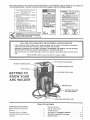
MATERIAL
THICKNESS
ON-OFF
ROEBUCK
AND
CO.
Sears Tower_
BSC 41-3,
Chicago,
IL 60684
LOCKING
KNOB
'IAMETER
GAUGE
GAUGE.
SWITCH.-.
GETTING TO
KNOW YOUR
ARC WELDER
DUTLETJACKS
HELMET
AND
ELECTRODE
WORK
TABLE
OPERATING
AND
WORK
CLAMP
OF CONTENTS
INSTRUCTIONS
Safety I nstructions to Operator ..............................
Warranty ............................................
Getting to Know Your Welder .............................
Unpacking and Checking Contents ..........................
Assembly
...................................
CABLE
HOLDER
2
3
3
3
4
Operating Controls ................................
Operating Instructions
...........................
Trouble Shooting
...............................
ARC WELD IT YOURSELF MANUAL
..............
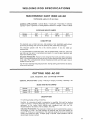
WELDING ROD SPECIFICATIONS
...............
REPAIR PARTS .....................................
6
7
8
1-1
2-1
2-6
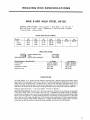
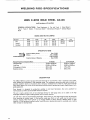
SPECIFICATIONS
Input Volts (AC):
...........
Hertz (Cycles):
................
Output Amperage:
........
Rated
Short
Input Amps:
Circuit
Input
...............
Amps:
.........
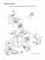
UNPACKING
SET-UP
Fuse or Circuit
Breaker Required: .........
Arc Voltage:
...............
KVA:
....................
KW: ...........................
230
60
30 to 140
40 to 230
50
66
AND
50 Amps
25
108
7 1
CHECKUNG
INSTRUCTIONS
This Craftsman welder is shipped complete in one carton
In order to facilitate packaging, certain items have been
removed at the factory and must be assembled when
Max
Open Circuit
Output
Volts
..........
Power Factor
...........
Duty Cycle:
........
Electrode
Capacity:
80
66%
20 to 100%
1/16"
to 3/16"
CONTENTS
received by the purchaser
Remove all items from the
carton and identify item as shown in the exploded view
illustration
These "Loose Parts" should be accounted for
before discarding any packaging material.
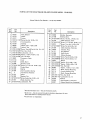
LOOSE PARTS LIST
Key
No.
Part Name
O.ty.
i
1
2
3
4
3
4
WeldingHelmet (Partially assembled) ..........
Helmet band assembly (Not Assembled) ........
Electrodecable assembly .........................
LooseParts Bag- Containing the following items:
Electrode Holder .....................................
Work Clamp ...........................................
Screw, Hex.-Hd., 1/4-20 x 3/4 in...............
Nut, Hex., 1/4-20 ...........................
Washer,Flat 17/64 in...............................
Loci{washer,1/4 in
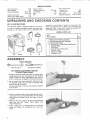
ASSEMBLY
TOOLS
NEEDED
,,lOinch
wrenchScrewdriver
(medium)
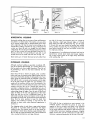
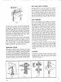
ATTACHING
ELECTRODE
TO ELECTRODE
I. Grasp the electrode
handle locking screw
handle Loosen this
until the handle can
HOLDER
CABLE
holder and locate the slotted head,
near the mid-point of the insulating
screw approximately
two turns, or
be slipped off the electrode bolder..
2 Do not remove this screw completely. Slide tile handle
off electrode holder and insert end of electrode cable
assembly through the handle.
The electrode cable is the one with insulation stripped
from
one end
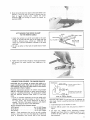
3 Using a screwdriver, back out the slotted-head set screw,
located near the end of electrode holder until the end of
screw does not protrude into the wire socket in the end
of holder
4. Make sure the wire strands on stripped end of electrode
cable have not been "frayed"
Twist together with
fingers if necessary.
5 Insert stripped end of electrode cable into electrode
holder and tighten the slotted-head set screw very
firmly
4
.............
....
t
1
1
I
1
1
1
1
1
1
_i_i
ii _'
_ i
6 Slide the handle back into place on electrode holder and
position it until the hole in handle is directly over the
head of handle locking screw
Tighten
the screw
clockwise
@
just enough to secure the Inandle on
electrode holder
ATTACHING
THE WORK CLAMP
TO THE WORK CABLE
SCREW
1. Attach the terminal on end of work cable to the work
clamp, at the hole near the nose of the clamp with the
1/4-20 x 3/4-inch screw, 1/4-20 nut, 17/64-inch flat
washer and I/4-inch Iockwasher furnished in the loose
parts bag
2_ Do not use either of the holes in handle ends of work
clamp
LOCKWASHNUTE_
HWORKCABLE
3_ Tighten the screw firmly enough to insure good contact
and prevent the cable terminal from slipping on the
clamp
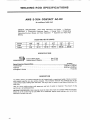
CONNECTING
WELDER
TO POWER
SOURCE
CAUTION:
Do not attempt to connect this welder to a
regular household outlet. Make sure the power-line voltage
and frequency agree with the ratings shown on the selector
plate attached to front of eabinet.
Electrical connections between the welder and grounded
230-volt, single-phase, 60-cycle a-c power source should be
made by a qualified electrician. All wiring must comply
with the National Electrical Code (ANSI C1) and local
codes
1. Install an individual (separate) line for the welder with
delayed action type circuit breaker or fuses in the line
For best results, this circuit should be as short as
possible The size of the supply conductors will depend
upon their length as shown in the table below
Supply Conductor (Incl. Extension Cords)
Up to 30 feet ............................
No_ 10 AWG Copper
30 to 50 feet .............................
No 8 AWG Copper
Over 50 feet ...................................
No 6 AWG Copper
NOTE - These conductor sizes are for use with a welder
having a rated input not more than 60 amps at 20% duty
cycle in accordance with Article 630 of the National
RECEPTACLE
k
GREENWIRE_.
Connect to
ground
bussin
Connect to hot wires o[ Q
powerponet
single phase system only
FUSES OR CIRCUIT BREAKERS
Electrical Code (ANSI C1) and may not be adequate for
other loads Consult a qualified electrician before using for
other loads
2
Install
3
Connect
50 ampere
230wolt
circuit
power
breakers
lines
or fuses
and
ground
as shown
in
figure
4
Use Sears Cat #20691
Power Receptacle available
through most Sears Retail or Catalog outlets or any
certified 50 amp, 250 volt, 2 pole, 3 wire, grounding
type receptacle.
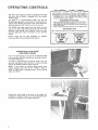
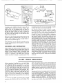
OPERATnNG
CONTROLS
_TAL
The name "dual range" arc welder is derived from the fact
that your new arc welder is equipped with two separate
welding ranges,
The beginner or less-experienced welder will find the
30-140 amp range easier to use because it provides extra arc
stability when welding with some of the "more difficult to
weld with specialty rods" which are prone to pop-outs
The 40-230 amp range requires less line (input current)
draw for any given amp setting and permits the use of the
maximum
amp settings with minimum
effect on other'
electrical appliances, motors, and lights, on your electrical
system,
Either
range
may
be used,
depending
on
preferences
when the electrode
diameter
permits
TABLE
REGARDING
1
1
2
3
POTENTIAL
AT THE
SHOCK
ON
SAME TIM
CABINET
CONNECT
ONLY TO A GROUNDING
POWER SOURCE
CONFORMING
TO THE NATIONAL
ELECTRICAL
CODE
(A N S I C1) AND LOCAL CODES
REGARDING
EYE
INJURY
WEAR WELDING
HELMET WITH NO 12 OR DARKER FILTER LENS
MEETING
REQUIREMENTS
OF A NSI.
Z87,1.
WEAR GOGGLES
OR FACE SHIELD WHILE CHIPPING
OR
BRUSHING
SLAG.
KEEP OTHER PERSONS AND PETS OUT OF WORK AREA
REGARDING
KEEP COMBUSTIBLES
uSE
OUT
FOR MINIMUM
LINE DRAW
FIRE
OF RANGE
UsE
OF WELDING
SPARKS
FOR MAXIMUM
ARC STABILITY
operator
AMP
RANGE/
CONNECTING
ELECTRODE
AND WORK CABLES
insert the tapered plug on the end of the electrode cable
into the proper outlet jack depending on amperage required
or operator preference.
To insure a good electrical connection always twist the
electrode plug slightly while inserting_ To remove the plug
twist in the opposite direction while removing
NOTE: If you extend the welding cables beyond those
already supplied, they must be No= 4 AWG or larger to
avoid an undue drop in welding current
Do not extend
cables over 50 feet,
Connect the work clamp to the piece to be welded, (to
complete the electrical circuit) or to the welding table itself
provided it is metallic or will conduct electricity!
AMP
Z
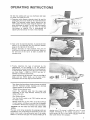
OPERATING
RNSTRUCTIONS
We feel that welding with your new Craftsman dual range
arc welder is as simple as A B C
A Determine what diameter electrode should be used by
gauging the piece to be welded on the material thickness
gauge The fractional number directly beneath the bar
chart dictates what the proper electrode diameter is for
given thicknesses of metals You will note that a specific
diameter
of electrodes
can be used on varying
thicknesses
of material. This is accomplished
by
adjusting the heat selector for more or less amperage•
B Next verify the electrode diameter, by placing the bare
portion of the electrode into the electrode diameter
gauge on the right side of the cabinet
Because electrodes are mass produced, there may be
small burrs on the bare ends of the electrode Make sure
the bare end of the rod is as clean as possible for
accurate sizing,
C, Finally,
determine
the type of electrode
by the
identification
on the package or by the American
Welding Society number stencilled on the coated portion
of the electrode, bearing in mind the type of electrode
you have chosen - E6013 or E7014, and also its'
diameter (as previously determined)_
Locate that band on the amp scale There are two E6013
bands and two E7014 bands, use the band which
coordinates with the amp range you have selected•
Now loosen the heat selector knob and move the pointer
until the fractional
number matching your electrode
diameter appears in the pointer window
Tighten the heat selector knob
Insert
the electrode
cable into the proper jack
(depending on the range selected), Connect the work
clamp to the work.
Wear Welding Helmet,
Turn the On-Off switch to the "ON"
are ready to weld
position
and you
Because metals vary in their make up and the technique
of each operator is different, you may find it necessary
to increase or decrease the amperage output accordingly,
CAUTION:
Do not loosen and move heat selector while
welding
The duty cycle ratings bracketing the amperage scales are
provided for your convenience and protection of your new
welder_ Duty cycle is the performance level of the welder
based on a 10 minute time span. For example welding for 6
minutes out of 10 minutes is a 60% duty cycle To avoid
possible overheating of the welding transformer,
which
could shorten the life of your welder, Do Not exceed the
duty cycles listed on the nameplate
7
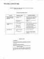
TROUBLE
SHOOTING
WARNING:
Removal of the welder cabinet top for any reason must be done by
a qualified service technician.
TROUBLE
TROUBLE
Fan and welder do not
operate, or continually
blow fuses.
Welding current low
or weak,
Can't hold an arc.
PROBABLE
SHOOTING
CAUSE
CHART
SUGGESTED
REMEDY
1. Improperly fused or
protected_
1. Use 50 ampere fuses of the delayed
action type such as "'Fusetron" or
"Fustat" or 50 ampere 240 volt
circuit breaker.
2 Blown fuse, or open
circuit breaker_
2 Replace fuse, or reset the circuit
breaker.
3_ "On-Off"
3 Turn switch "On".
switch not "On".
1. Low line voltage,
1_ Have a voltage check performed
the local power company_
2_ Welding current
setting too Iow_
2. Check current recommended for
the electrode being used.
3, Poor connections.
3, Check electrode holder, work and
electrode cable connections
1 Using a D.C. welding
rod.
1_ Use AC or AC-DC rods
2. Low hydrogen rod
2, Use rod of 1/8-inch maximum
dian'leter, or' smaller on 30-140
amp range.
SERVICE
TIPS
FAN MOTOR
No provision has been made for lubricating the fan motor,
as extra large oil reservoirs provide lubrication for the life
of the motor.
SELECTOR
PLUGS OR CONTACTS
WARNING:
Be positive you have disconnected the power
supply to the welder_
If for any reason the selector plugs or mating contacts
become burned or pitted, tiley should be cleaned-up with a
fine grade of emery cloth or dressed very lightly with a fine
file,
by
f
A COMPREHENSIVE
GUIDE FOR YOUR
NEW CRAFTSMAN
ARC WELDER AND
WHAT iT W_LL DO
CONTAINS:
INFORMATION
o VARIOUS
o USEFUL
ABOUT
TYPES OF RODS
ACCESSORIES
TIPS ON CUTTING,
AND BRAZING
WELDING
,,,J
Form No SP574-4
1-]
IJELD
gT Y©U SELF
TABLE
OF
CONTENTS
Page
Your WelderandWhat It Will Oo .............
1-3
How the CraftsmanContactRodSimplifiesWelding 1-3
What HappensWhenYou Weld? ..............
1-3
ReadBeforaWelding .......................
14
LearnBy Doing ..........................
1-5
PositionWelding .........................
1-11
Cast-IronWelding ........................
1-14
HardSurfacingWornCutting Edges ..........
1-15
TheTwin CarbonArc Torch ...............
1-16
CuttingandOther Miscellaneous
Operations ..o
1-17
Inert-GasMetal-ArcWelding ................
1-19
Read this Manual
carefully
for additional
SEARS, ROEBUCK AND COMPANY
AND SIMPSONS-SEARS LIMITED
1o2
welding
information.
YOUR
WELDER
and what it will do = °.
Your CRAFTSMAN Arc Welderis a sturdilyconstructedend thoroughlytestedmachineengineeredto
give many years of efficient trouble-free service. It is listed by Underwriters' Laboratories,
incorporated,which meansthat it passesall requirementsof safety,fire hazardand temperaturerise
limits asspecifiedin theirStandard for Transfer-TypeArc-WeldingEquipment,
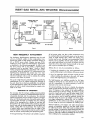
HOW THE CRAFTSMAN ELECTRODE
SIMPLIFIES WELDING
Craftsman
Contact Electrode is self-starting-plus
restarting , The electrode startson contacL
automatic
Craftsman Contact Electrode is serf-cleaning..... Under normal
conditionsthe slagremovesitselfasthe weld cools, Spatter is almost
nen-existenL Craftsman Contact Electrode has an exceptionally
good appearance _
With fine ripple, unusually clean, smooth
appearance,andreduced slaginclusions
Craftsman Contact Electrode depositsmore metal faster
the powdered iron in the flux goesinto tile weld_
. Because
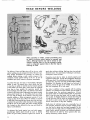
Arc Welding is the process of fusing two or more pieces of
metal together to form one piece. It is accomplished by
heating adjacent metal surfaces to the melting point with an
electric arc, then adding a sufficient amount of molten
metal to provide reinforcement and fill any vacant space
between the parts being joined, as shown in the accompanying illustrations
The arc is created when an electric current, regulated by
a welding transformer, flows across an air gap between an
electrode and the work being welded, The intense heat
generated by the arc is ideally suited for welding, as it
can be directed to affect only the part of the metal to be
welded, Uniform heat from the arc, is acquired by keeping
its length the same for a given rod size and current setting,
At the instant an arc is "struck", a portion of the base
metal directly beneath it, is melted, resulting in a small
pool of molten metal, some of which is forced out by the
blast of the arc and deposited along the weld path, The
depth of the crater thus formed, is the distance the weld
will extend into the base metal and is referred to as the
penetration of the weld
1
3
Beth edges of the metal
are heated by the arc,
until --
mere molten metal and
flux is added from the
rod, which5
2
4
they melt and flow to
gether forming one piece,
instantly --
fills the crater andcovers
the top of the weld with
slag,
This process continues the entire length of the weld
Some of the electrode (which consists of o metal rod surrounded by a flux coating) is melted simultaneously with
the base metal and is carried by the arc to the liquid pool
This added metal combines with the base metal to form
the deposited weld,
During th_s operation a part of the flux coating burns off
and forms a gaseous smoke screen that completely envelops the arc, protecting the molten metal from harmful
effects of oxygen and nitrogen in the surrounding atmosphere, The remainder of the flux coating that melts is
carried to the molten pool where it mixes with the metal
to combine with various impurities It then floats to the
surfaces to form a coating of slag which covers the deposited weld metal, protecting it from the atmosphere and
retarding its cooilng
I-3
READ
5EFORE
WELDI NG
When operating a welder, certain precautions must
be taken to prevent minor injuries to yourself and
others, Although injuries may not be serious or permanent, knowing
how to use the protective equipment to safeguard against them is the first step in
learning to weld_
The effects of heat and light given off by the arc, while
electric welding, may be compared to that of the sun's rays_
Even greater precautions are necessary for electric arc
welding. Before starting a weld, caution anyone in the
immediate vicinity against looking at the arc_ in case of
occidental eye injury, contact a physician immediately.
To protect the face and eyes a heat-resisting, fibreglass
helmet is used. The special tens, which allows the user
to view the arc safely, is inserted into the framed opening
of the helmet The clear glass, which should be replaced
from time to time, protects the expensive special lens
from breakage and weld spatter. The helmet is held firmly
in place on the head with an adjustable head band, thereby
leaving both hands free° A close-flttlng skull cap should
be worn with the helmet° As the helmet is used only when
actually welding, a tilting arrangement permits it to be
swung up clear of the face. When the welding is resumed
a slight nod of the head tips the helmet down over the face.
To protect the eyes further while cleaning the weld, goggles
should be worn by the welder and others working around
him_ Animals are also affected by the rays and should be
kept at a safe distance_
To safeguard the hands against heat and weld spatter,
gauntlet-type
leather gloves should be worn. A leather
jacket will give better protection against the shower of
1-4
sparks than ordinary clothing. High top shoes (not oxfords)
should be worn. If a great deal of welding is to be done,
foundrymen's shoes are best.
Precautions must also be taken to protect property and
equipment against flre_ A large fire extinguisher should be
within easy reach. The welding area should have a concrete
or cinder floor, kept dry and clear of inflammable rubbish.
Sometimes, it is necessary to weld close to a fuel tank. If
practical, remove the part to be welded. If not, drain the
tank and completely fill it with water.
Few tools, in addition to those supplied with the welding
machine, are needed and most of them can be found in
the average shop Two sawhorses supporting a 1/4-inch
steel plate makes an excellent welding table A permanent
bench, using the same steel plate, can be made of angle
iron or pipe. A chipping hammer is used to clean slag off
a weld and pliers will be useful for handling hot metak A
wire brush is used to clean the work before welding and
remove small pieces of slag after chipping_
Small pieces of mild-steel scrap iron, reasonably free of
rust and paint, should be used for practice welding_ Angle
iron, bar stock or plate steel are good examples. Do not
use scrap cast iron, high carbon or hardened steel as these
metals require special electrodes and welding techniques.
These should be set aside for future practice after completing elementary practice lessons°
LEARN
BY DOBNG
I
90
OFWELG
OIRECTiON
Experience has proven that short periods of practice at
regular intervals are the best way to teach yourself how
to weld. As learning to weld is simply a process of trial
and error, all practice work should be done on scrap metal
that can be discarded. Do not attempt to make repairs on
valuable equipment until you have satisfied yourself that
your practice welds are of good appearance and free of
slag or gas inclusions. Remember, what you fail to learn
while practicing, must be learned through a series of
mistakes and rewelds later am
A comfortable body position is important when learning,
as tensed muscles will result in fatigue and lack of control.
Sit on a low stool and grasp the electrode holder in one
hand with the cable drawn across the lap. Allow enough
slack to move the holder freely and yet keep the weight
and drag of a long length of cable from becoming tiring,
The ground connection is as much a part of the welding
circuit as the cable and electrode holder_ A poor ground
connection can render the best welding equipment inefficient. When using a table with a steel top, fasten the lug of
the ground cable to it securely with a bolt or C<lamp, so that
any piece of iron placed on the table top will be propedy
grounded. If a steel table is not used, connect the ground
cable d_recfly to the work with a ground clamp or bolt
Select a fairly large piece of steel plate approximately
1/4-inch thick and clamp it to the table top to prevent it
from lifting, should the electrode stick or "freeze"
when
first attempting to weld. insert a small, mild-steel welding
electrode in the electrode holder and connect the welding
cables to produce the heat specified by the CONTROL
panel Connect the ground cable to the work and set the
indicator in the current
range recommended for the
diameter of rod used.
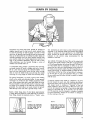
Any method of bringing the tip of the rod in contact with
the work, then quickly raising it until there is approximately
a 1/8-inch gap between the rod and the work, will start an
arc_ The easiest way for a beginner to strike an arc is to
scratch the tip of the rod a short distance on the surface of
the work, as you would a match, then lift it (quickly) the required 1/8-1nch (fig. 1). Another method is to strike the work
a hard blow with the tip of the rod and allow it to bounce
up to form the arc gap. The important thing is to strike
the arc qelckly and not allow the rod to remain in contact
with the work
A common mistake often made by a beginner is to point
the rod toward the work and, after lowering the helmet,
feel slowly about until the tip of the rod touches the work.
This always results in sticking or "freezing"
of the rod
which produces a direct short circuiL When this occurs the
rod can be loosened by bending it from side to side while
pulling on the holder (fig 2). If this fails, turn the welder
off_ The electrode must be released in a matter of seconds
to avoid unnecessary heating of the welder or damage to
the flux coating on the rod
,'/,'II'U]I
Figure
,,',/
1
Figure 2
\\
To strike an arc, scratch the
end nf the red ne the plate
and then quickly raise approximately 1/8-inch,
Should the rod stick or
"freeze" bend it from side
to side while palling upward
on the rod ho_er.
\
\
/
\
I
/
1-5
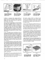
Figure 3
To lay a weld bead only two
movements are used, dowfiward and in the direction the
weld is to he laid.
Figure 4
Figure 5
Watch the weld puddle to
keep the slag from flowing
in front of it, causing inclusions and gas pockets
Fill the crater, when starting
a new rod, by striking the
arc at A then moving to 8
and back to C position
If difficulty is experienced after repeated attempts to
maintain an arc, check the ground connection for proper
contact with the work If this does not help, increase the
welding current Also check the rod size, as larger rods
require higher current settings.
Practice striking and maintaining an arc for a few seconds,
then snap it out by rapidly pulling the rod away from the
work_ Repeat this operation until the arc can be started
and the gap maintained as uniformly as possible. In a
short time you will find the arc length can be controlled by
the crackling or "frying" sound which may be recognized
by gradually shortening the arc until it sputters irregularly
as though it were going to "choke out'* and stick--then
slowly lengthening the arc by pulling the rod away from
the work until it snaps out_ Somewhere between these two
extremes the steady crackllng sound of a proper arc length
will be heard_
To lay a weld bead, only two movements are used, a
steady downward feeding of the rod to maintain the correct
arc length and a slow travel in the direction in which the
weld is to be lald (fig. 3)_ Watch the weld puddle and
arc length, and move the rod steadily in a straight llne as
the back end of the crater fills up (fig 4). The slight angle
of the rod will keep the flux or slag flowing over the
deposited weld metal to form a protective coating. If the
rod is moved too slowly the slag will flow in front of the
puddle and be trapped in the weld, producing inclusions
and gas pockets.
Lay a bead approximately four inches long. After allowing
it to cool slightly, remove the slag coating, which covers the
top of the weld, by scraping along each edge of the weld
with a cold-chlsel foJowed by wire brushing until it is bright
and clean_ Inspect the surface of the weld carefully before
starting another_ The surface of a good weld is rippled
unlformly, which results from a steady rate of travel and
uniform arc length_
Figure
6
To widen the head, work the
red from side to side slight
ty, with a slow, zigzaggmg
crescent-shaped motion
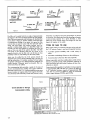
After laying a number of beads, try "working"
the rod
from side to side slightly (fig. 6) This movement should
be slow and not wider than the diameter of the rod being
used. Experiment with different current settings, rod sizes
and rates of travel.. Compare results with welds shown in
the diagrams (fig, 9).
Too low a current setting tends to deposit the bead on top
of the plate with very little penetration. The arc sound will
be an intermittent crackle with irregular sputtering Too
high a current setting (for the size of the rod being used)
wiII provide sufficient penetration but the bead will be thin
and undercut in places. The arc makes a hissing sound and
the rod becomes red hot before it is half used.
If travel is too slow it will pile up a wide, heavy bead with
good penetration but with overlap of the weld metal on
sides without fusion_ A large area surrounding the weld is
heated to a high temperature which produces distortion,
even on a simple weld If the rod is moved too fast the
small bead will result w_th little more than melted base
metal. An extremely long arc causes the rod to melt off in
globules, with little or no penetration, and a very irregular
weld surface The arc produces a hissing sound.
A good weld laid with correct current setting, speed and arc
length will produce a surface that is rippled uniformly, with
the same width throughout its length, and well formed
crater. The cross-sectional view shows it to have good penetration and no undercut or overlap.
I
I
If the scrap plate used is small, it will become very hot after
laying a few beads. This will alter welding conditions
which could be very confusing to a beginner Have several
scrap pieces handy so each may be allowed to cool before
laying a second bead,
When starting with a new rod, chip slag from the crater
and strike the arc at the forward end as shown at "A" in
figure 5, Then move the rod to "B" and back to "Ci" at
about twice the normal rate of travel to give the rod and
base metal time to heat up for proper fusion
1.6
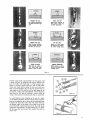
Figure
7
Lay the weld beads about
one inch apart, ffemove the
slag and examine each weld
before starting the next
Figure 8
A pad of weld metal is built
up by running a series of
beads in layers at right
angles to each other,
CURRENTTOO LOW
Arc is difficult to maintain.
Vurylittle peflctrationHigh
bead,
TRAVELTOO FAST
Small bead undercut in
some places. Rough top
and little penetration
CURRENTTOO HIGH
ARC TOO LONG
Wide thin bead, undercut,
Crater pointed and long,
Rod hurns off very fast,
Surface of weld rough
Rod melts off in globules
Arc makes hissing sound.
TRAVELTOO SLOW
NORMAL CONDITIONS
Metal piles up. making a
wide heavy bead, over°
lapped at sides in places
Uniform ripples on surface
of weld, Arc makes steady
crackling sound,
Figure
Practice laying beads approximately
one inch apart until
a good weld can be produced with all the different rod
sizes the welder will handle (fig, 7). After becoming proficient in running a bead, build up a pad of weld metal,
Clean each bead before laying the next and make sure
they are fused together (fig. 8) Run the second layer at
right angles to the first and the third at right angles to the
second, etc_, _sntil a pad approximately
1/2-inch thick has
been built up This type of welding is used to build up
round or flat surfaces or reinforce parts that are rusted thin_
9
F_gure 10
To avoid distortion when building up the end of a shaft,
run the beads parallel to the axis and lay each successive
bead on the opposite side as shown by the numbered steps
in figure 10. Cover the entire shaft with weld metal for
the desired length. If the place to be welded is not at the
end of the shaft, weld around it and turn the shaft slowly
to keep the weld puddle in the flat position (fig_ 11). Clean
off the slag after each bead, then machine the shaft to
proper size.
1-7
FLAT
WELDING
SLIGHT / /
GAP / ,
St;EEl"
METAL
k___J\
Figure
TACK
•
Figure
BACK-UP
STKIP
4
3
WELOS
REINFORCEMEHT
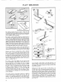
Flat welding includes all types of joints in which the weld
is horizontal, and the electrode is fed down as in the practice
welds of previous pages The five types of joints in figure 1
can be welded in the flat position
Butt welds on llght material should be practiced first on
scrap stock_ Use 16-gauge mild steel sheet metal (approxi=
mately 1/16-inch thick) and 5/64-1ech rods with the welder
set at approximately 30 to 50 amperes, Butt edges of metal
together and tack-weld approximately
every three inches
(fig. 2)_ (Tack welds are small beads 1/4 to 3/8-1nches in
length_) Place bars of scrap iron under ends of the work to
provide an air space above the table. Simply move the rod
in a straight llne directly above the edges to be joined.
Figure 5
Figure 6
Figure 7
If the weld burns thro.ugh in places, reduce the welding current or increase the rate of travel. Some difficulty may be
experienced in starting the arc at these low current settings
However, once the arc is started, there wlll be sufficient
heat to make a sound weld. After laying a bead, turn the
work over and inspect the underside which should also have
a small uniform bead. To prevent burning through where
the edges are not butted tightly together, move the rod back
and forth with short quick strokes in the direction of the
weld to bridge the gap and give the metal in the crater a
chance to solidify (fig 3).
Butt welds on sheet metal lighter than 18 gauge should
not be attempted by the beginner without the use of a
back-up strip (fig 4). This consists of a bar of copper
clamped tightly against the underside of the seam to absorb
the heat of the arc and prevent the weld from burning
through To assure complete penetration with butt welds
on 8-gauge metal or heavier, a 1/16 to 3/32-1nch gap
should be allowed between them (fig .5) insert a wedge or
screwdriver between the plates when tack-welding to main*
tain the gap, then turn the piece over, so the tack welds are
on the underside_
Use enough current to melt edges of plates to a depth of
at least one-half their thickness Clean off the slag and
inspect it for smoothness, penetration and height of reinforcement Agood weld should havea relnforcement slightly
more than flush with the surface (fig 6) Turn the plate
1-8
over and weld a similar bead on the other side (fig. 7) A
higher weidlng current can be used on this side as there is
no danger of burning through and fusion with the first
bead will be assured
Although butt welds can be made on steel plates up to
3/8-inch thick, with a 295-ampere machine using 1/4-1nch
rod, the same results can be obtained with the 180 and
230-ampere machines if edges of plates are beveled (fig. 8)
Metal of almost any thickness can be welded in this manner
by depositing a number of beads, one on top of the other
until the groove is completely filled= If the plate can be
welded from both sides, always use a double bevel (fig_ 9)_
If only one plate is beveled, the angle should be at 45 degrees (fig 10)
Run the first pass on beveled plates with a 5/32-1rich rod
and use as high a current as you can handle to obtain a
small bead on the underslde_ If this is not done, insufficient
penetration will result, as shown in figure 11. Be sure to
clean each pass before laying on the next All beads are
la_d by moving the rod in a straight llne with no weaving
or slde-to-side movement_ On the last or reinforcing pass,
a weaving motion must be used to obtain a wide weld that
will completely cover preceding beads. For the beginner,
the slde-to-side movement (with a slight hesitation at each
end) will produce a smooth top without undercut or overlap
UNDERCUT GASPOCKET
EHT
PENETRATION
Figure
II
Figure
Figure
12
13
FgLLET
Select several practice welds of different thicknesses and
cut them into 1-1/2-inch strips. Clamp each strip in a vise
and bend it at the weld (fig. 12)_ If it breaks through the
weld, study it to find the cause of failure
Corner welds are made on light sheet metal by running
a single bead along the top, after tack-weldlng at threeinch intervals to prevent warping (fig 13)_ if numerous gaps
are present, a back-up strip may be used, On heavier
metal two passes may be necessary and, if the design
permits, a smaller pass can be lald on the underside.
Beveling may be used to advantage on the thicker metals
WELDS
I
I
WELD
BREAKING
THEWELD
Figure
4
Fi9ure
6
WELD
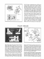
Fillet welds are used to join two pieces of metal with sides or
edges at right angles to each other The size of such a
weld is based on the leg length of the largest isoscelesright
triangle that can be inscribed within the cross sectional
area, as shown by the dotted-line triangle (fig 1). The
size of a fillet weld may also be measured with a square
and ruler, subtracting 1/32-inch from all dimensions under
3/16-inch and 1/16-inch from all over 1/4-inch (fig. 2)
For example, a 1/4-inch fillet weld should measure 5/16inch This will offset any inaccuracy due to the slight radius
at the toe of the weld and allow for concavity of the bead.
When a fillet weld is stressed to its maximum capacity,
failure will usually occur through the throat section (fig. 3)
Therefore, the strength is determined by the throat dimension multiplied by the Fength of the weld Finished welds of
this type should always be at least four times their size in
length; that is, a 1/4-inch fillet weld should never be less
than one inch long, The direction in which the load is applied
to a weld greatly affects its strength, which can be clearly
demonstrated by breaking the weld (fig 4) A joint so
roaded should always be welded on both sides with fillets
equal to the plate thickness (fig 5) If this cannot be done,
bevel the plate to assure complete penetration and position
the work at a 45-degree angle if possible.
For practice, tack-weld three pieces of scrap iron together
to form a cross (flg_ 6) Use a 5/32-inch rod with high current
and hold it as indicated in the front and side views. Move
the rod at a steady even pace along the seam without any
side-to-side movement and deposit one inch of weld for
each inch of rod melted. The surface contour of a good weld
1-9
ROD
SIZE
UNBERCUT
f _P
_,,-CENTER
_OF SEAM
Figure 8
Figure 9
Figure
Figure
11
10
INTEBMII_ENT
WELOS
I'_
!EXCESS
BLA
Figure
13
Figure 16
STAGGERED
INTERMITTENT
WELOS
Figure 17
LAPWELDS
Figure
14
LAPWELDS
Figure
15
should be nearly flat with a slight radius at the sides or
toes_ Avoid excessive concave or convex surfaces of the
fillet (fig_ 7) Undercuts and colddaps are caused by not
holding the rod in the center of the seam (flg_ 8)_ if the
desired fillet weld cannot be made with a single pass,
several passes are used to build it up to required size (fig_ 9).
Slag must be cleaned from each pass before depositing
the next. Fillet welds over 1/2-inch in size are rarely used
because joints requiring more strength can be made more
economically by beveling and groove-welding,
followed
by a small concave fillet weld to provide a radius in the
corner_
Horizontal fillet welding is used when the side or edge of
one member of the joint is in the vertical position particularly
for small single-pass welds where the work cannot be tilted.
For practice, tack-weld two pieces of scrap together to
form a tee-joint (fig. 10)_ Use a 5/32-inch
rod held at
angles indicated, and direct the arc into the corner of the
joint. The arc length should be somewhat shorter than for
flat fillet welding_ To assure penetration at the root, use the
highest welding current that can be handled (fig 11)_
Good penetration is of prime importance and appearance
1-10
WELDON BOTHSIDES
AT ENDOF JOINT
will come with experience. If the arc is advanced too fast,
or held too close to the vertical plate, undercutting may
result (fig. 12). Too slow travel will cause overlapping and
an extremely dose arc or low current will produce a bead
with a convex surface (fig. 13). To check the penetration and
soundness of the bead, break some of the welds for inspection, as shown in figure 4_
When making a lap weld, care should be taken not to melt
too much of the upper corner on the top plate (fig. 14)
Some melting will take place, but proper advance of the
rod will cause the weld metal to build up and blend into the
top surface. On sheet metal, hold the 3/32-inch rod almost
perpendicular
and move the arc rapidly. Welds of this
type should be wider than they are high, somewhat like a
flat bead (fig_ 15) A slight discoloration on the underside
of the lower sheet indicates good penetration, On heavy
metal, a 3/8-inch fillet weld can be lald in one pass with a
1/4-1nch rod using a 295-ampere machine However, with
smaller machines, the same weld or larger can be made by
building up with a number of passes (flg_ 16)_ When
welding long narrow pieces, stagger the welds in short
intermittent beads, first on one side then on the other side,
to minimize distortion (fig_ 17).
_i_
_¸ _
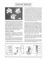
POSMTION
BUTT WELD
in order to derive the greatest benefits from your welder,
you should practice until you can make a welded iolnt
in almost any conceivable position. The ability to do this
is especially useful when making repairs on machinery as
the amount of welding in most cases is small and does not
warrant disassembling the parts to weld them in the flat
position Welds of this type have been classified into three
groups according to their location and are referred to as
vertical, horizontal and overhead welds (fig 1) Of the
three positions, vertlca[ welding will be used the most and
should be practiced first. Skill gained in this type of weld
will make horizontal and overhead welding easier
VERTICAL
WELDING
The two methods of welding in the vertical position are
commonly known as "vertlcal-down"
and "vertlcal-up"
welding (fig_ 2)_ In the former the bead is started at the
top and welded in a straight llne downward In the latter
the bead is started at the bottom and welded up, usually
with a weaving motion
The chief difficulty encountered with any position weld is
keeping the molten metal in the puddle from falling out.
To prevent this the arc must be held as short as possible and
the weld puddle kept fairly small so it will solidify rapidly
Verficabdown welding is the easiest to perform and is used
on material up to 1/8-inch thick Before attempting a vertical
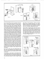
__
WELDING
weld, run a few practice beads to get the feel
of the
arc_ Tack-weld a piece of scrap iron to an old practice plate
so it is positioned vertlcal]y (fig 3). Use l/B-inch rods for
the first welds and a current of about 75 to 115 amperes
Experiment with various amperage settings until you are
using the highest current you can handle Hold the rod at
right angles to the plate laterally, with the tip pointed up
at the angle shown in figure 3 Start the weld at the top
of the plate and move the rod in a straight line downward
The correct rate of travel can be determined by gradually
reducing the speed unti! molten metal in the puddle can no
longer be kept in place Then, increase the speed slightly
while watching the puddie, arc length and angle of the rod
A short arc provides better control of the molten meta!
Follow the same procedure with 3/32 and 5/32-inch rods
It will be noted that the larger the rod the more difficult it
is to control the puddle For this reason smatler diameter
rods are always used for position welding
Lap or tee-joints are made by simply directing the arc into
the cornel of the joint as in fiat welding and moving the
rod down the seam at a steady pace Butt welds may require
more practice, as there is a tendency to burn through on
light gauge material if this occurs, continue until the seam
is completed and patch the hole by chipping the slag and
wire brushing until clean Then, with slightly lower current,
strike an arc on the weld directly above the hole and quickly
bring the rod down to the lower rim of the hole to deposit
a small amount of metal Raise the rod far an instant to
let the metal solidify and repeat until the hole is welded
Hold a long arc when raising, so there will be no metal
deposited except when the rod is lowered Any hesitation
in the rate of travel will cause a "burn through/'
if this
happens repeatedly, lower the welding current
Leave a slight gap between pieces for butt welds on material
over 3/32-1nch thick_ Inspect the back side after welding
for small bead along the seam, indicating complete penetration (fig 4) Butt joints on material around 3/16-1nch
thick should be welded on both sides.
Vertical-down welds may be made on heavier material by
laying in a number of passes (fig 5), however, this practice
is not recammended as it takes longer than a heavier single*
pass weld made by the vertical-up method
VEBTtCAL-
OOWNWELO
VEffTICAL.DOWN
WELDING
DlflECTIOH
BKVEL
3
PASS
-2HO
PASS
-IST FkSS
A SMALL BEAD OH
BACK SiDE [HBICATES
COMPLETEPEHETRATIOH
Figure
/3EB
Figure 4
Figure
$
I-I1
VERTICAL*UP 90°
WELOIHG
Figure
Figure
9
6
4",
J
Figure
Use 1/8 and 5/32-1nch rods for all vertical-up welds and
start by running practice beads from bottom to top of a
3/16 or 1/4-inch plate, tack-welded in a vertlca_ position
Hold the rod as shown in figure 6, noting that the angle
of the rod is not as steep as for vertical-down welding, but
tilted just slightly (approximately five degrees) so the tip
of the electrode points upward. Strike and hold o short arc
until a small amount of metal is deposited, then quickly
raise the rod upward with a wrist movement to increase the
length of the arc at the top of the stroke (fig. 7). As soon
as the metal deposited in the crater has solidified, bring the
rod down and deposit more metah Keep repeating this
whipping motion, while gradually moving the rod upward
and toward the plate as the electrode burns off. The length
of the stroke will depend upon the amount of metal de_
posited and the welding current esed_ Keep the rod in
constant motion once it has left the crater. The purpose
of a long arc is to prevent any metal from being deposited
except when the rod is held at the crater. If globules of
molten metal drop from the tip of the rod when the arc is
lengthened, either the current is too high or the rod has
remained away from the crater too long. Care should be
token not to break the arc at the top of the stroke. Do not
deposit too much metal at one time as this will cause the
weld to sag and result in a high narrow bead undercut
along the sides. Better penetration can be had by the
vertical-up method_ This can be demonstrated by ioinlng
two pieces of 3/16-inch metal with a butt weld, using the
whipping motion.. Leave a gap between the plates and use
a 5/32-inch rod with a fairly high current, determined by
experimenting. The whipping motion will melt the corners of
the plate and form a pocket in which to deposit the weld
metal (fig_ 8)°
weave (fig 9). This will produce a "shelf" upon which
additional metal is deposited _ntermlttenfly as the welding
progresses. There should be a slight pause in the weaving
motion at the toes of the weld to avoid making a bead that
is too convex. Materials 1/4-inch and thicker must be beveled on one or both sides, depending upon the joint
Practice making a wide bead using a side-to-side weaving
motion with a very slight whipping action at each end to
give the metal at each end a chance to solidify and avoid
undercutting along the sides of the weld (fig 10). This type
of bead is used on welds that require more than one pass
and is called the finish bead or "wash" pass. Hold a short
arc, making the bead approximately
3/4-inch wide and
fairly light, Multiple vertical welds may be made as shown
in the series of diagrams, figure 11_
Burn the rod in deep so the crater extends through to the
back side. After completing the weld, inspect the back
side for the small bead, which indicates 100-percent penetration. Butt welds on heavier materials should be welded
on both sides.
On materials up to 1/4-inch thick, use the whipping motion
on small single-pass fillet welds for lap and tee-joints Larger
single-pass fillet welds can be made by the whipping motion
with a slight side-to-slde weave added and combined with
the up and down movement to make a triangular shaped
1-12
TO
Figure
11
_/_
Figure
UHRERCUT
Figure
12
DEPOSITMETAL
OH GOWHSTROKE
OVER-LAPPED
Figure
HORIZONTAL
14
13
I]ACI(-Up STRIP
Figure
WELDING
Horlzontal welding refers to one type of butt weld between
two plates in a vertlcal plane. For practice, set up a plate
as for vertical welding and run straight beads across from
left to right (fig 12)_ Use the same current settings as for
vertlcal-down welding and hold the rod as indicated with
a short arc. Move the rod in a straight line and deposit
a light bead. The rate of travel will depend upon the current
used Too slow a travel will cause the bead to sag (fig 13).
Practice with 3/32, 1/8 and 5/32-inch rods untll a wel!
formed bead can be made with each size rod (fig 14).
Sheet metal up to 1/16-inch
OVERHEAD
15
thick can be butt welded from
one side_ if the seam has numerous gaps, use a back-up
strip, albwlng
a slight gap between edges of 1/8-inch
thick metal and weld from both sides (fig 15), All metal
3/16-1nch thick and over should be beveled and welded
with a number of passes (fig_ 16) Thoroughly clean each
bead before laying the next and use higher current than
for single-pass welding
The appearance of a multlple-pass horizontal weld can be
improved by vertical down beads laid closely together.
Use a swift circular motion to the right; slowly downward
while welding (fig 17)
WELDING
Although overhead welding is generally considered difflcelt, do not become discouraged, as it is being done every
day by people who have taught themselves_ Once theeart
of maintaining a short arc has been mastered, the rest
will be easy
Since there will be a shower of sparks, wear a leather
jacket and keep the practice plate slightly higher than the
top of your head when standing To keep sparks out of your
glove, grasp the electrode holder as indicated in figure 18
and hold the rod in a nearly vertlcal position with a slight
tilt to the right_ Drape the cable over your shoulder so its
weight will not interfere with the use of the electrode_ Use
1/8-1nch rods and a current setting the same as for vertical
welding, and move the rod in a straight llne without any
weaving or whipping motions A reasonably fast rate of
travel must be used to prevent the bead from sagging and
undercutting along the edges. Vary the rate of travel and
notice its effect on the size and appearance of the weld.
When you feel you can run a satisfactory bead, try the
slde_to-side weaving motion and deposit a thin weld approximately 3/4-inch wlde_ The movement must be somewhat
faster than for other positions to keep the bead from
sagging (This method of weaving is used only for the
last pass on heavy welds where improved appearance is
necessary)
The whipping motion is used where a gap exists between
the plates as it provides better penetration with higher
we]dlng current, For practice work, set up two plates approximately 1/8-inch thick, allowing a gap between them
Burn in deep for good penetration with 1/8 and 5/32-inch
rods, varying the plate size and gap distances.
Figure
19
Fillet welds for lap or tee-joints are most common in the
overhead position. Tacbweld
two pieces of scrap iron
together to form a tee-jolnt, and clamp in the overhead
position so one plate is held vertically (fig. 19)_ Hold the
rod at angles indicated and deposit a light bead from left
to right without weaving or whipping movements. A slightly
higher current than used for overhead butt welds will be
necessary to get good penetration at the root of the weld
t-13
METAL
BENDS
WHEN COOLED
DISTORTION
Figure
22
WHEN
TRENOS
COOLING
Egff W[LO
[RtH
F
Y_LO
Figure
23
Figure 20
Figure
Figure
To simulate actua! conditions tack-weld a piece with an
irregular edge to another piece leaving numerous gaps
along the joint_ Use the whipping motion and deposit a
fairly heavy bead, slowing down the rate of travel where
the gaps are widest to build up a weld of uniform size
throughout its length. If the gaps are rather wide, fill them
first, clean off the slag and lay in a fillet weld the entire
length of the joint (fig. 20)
When you can lay single-pass butts and fillet welds you will
be able to make an overhead weld of any size, as it is
simply a matter of fusing a number of straight beads together, one on top the other (fig 21)
Weld appearance can be improved by grinding with a
properly guarded abrasive wheel mounted on the end of
a flexible shaft
EXPANSION
AND
CONTRACTION
Metals expand when heated; contract when cooled. In arc
welding, the deposited metal and edges being joined are
molten and the metal surrounding the weld is heated sufficiently to cause expansion_ When the deposited metal
solidifies, it becomes a part of the plates; but, being unrestricte_ in its expansion in the molten state, it tends to
contract more than the heated surrounding metal If the
CAST
IRON
Previous experience in handling the arc, plus good judgment regarding
expansion and contraction, will enable
you to weld gray cast iron successfully in a short time.
Two types of electrodes are used, namely: non-machinable
for use in cases where the weld does not have to be
machined, and machinable which deposits a file-soft weld
that can be drilled or machined to close tolerances Nonmachinable rods are used for most repair jobs such as
cracked motor blocks, water jackets, pump and gear housings, etc. If the weld must be made across a machined
surface that need not be refinished to a close tolerance,
the face of the weld may be ground flush with an abrasive
wheel.
As cast iron is very brittle, care must be taken to control
expansion and contraction, and thus avoid cracking of the
1-14
24
21
surrounding metal is free to move (not clamped or tacked)
it cannot resist these forces and bends (flg_ 22)
The weld also contracts in width, as well as in length,
tending to pull the plates together, resulting in locked-up
stresses (fig_ 23) This is not too serious when welding mild
steel up to 1/2-inch thick, as the ductility and elongation of
the metal will pelmit it to deform slightly to compensate
for these forces, and prevent cracking. On sheet metal and
light structural members, long continuous welds may cause
considerable bending and resuJt in a badly distorted weldment Fortunately most of this can be avoided by studying
the effects of expansion and contraction, as related to the
job before welding and working out a procedure to follow.
For example: first assemble the job with tack welds, and
install temporary braces tack-welded to support parts that
might bend. The braces can be removed after the job is
cornpleted_ Lay the beads so the stresses will counteract
or nbutralize one another, by running a short pass first on
one side then on the other, etc. Often the neutralizing weld
is at the other end of the job Do not concentrate too many
welds in one place but space them to distribute the heat
and stresses throughout the entire structure Use intermittent
welds whenever possible_ If continuous welds are necessary
to make a water-tight compartment,
use the back-step
method as shown in figure 24, fusing each bead together
at the end
WR=LD|NG
weld or the casting_ Because of low tensile strength and
lock of ductility it cannot bend, stretch or distort itseff to
conform to the contraction of the weld metal In some cases
it may be necessary to pre-heat the entire casting before
welding_ However, as most cast iron welding jobs can be
done without pre-heatlng, this method will be considered
first.
The part must be free of rust, grease, paint or dirt; cleaned
by wire brushing, grinding or washing with solvent. The
crack should be beveled for penetration. If the parts are
broken apart completely,they may be ground on an abrasive
wheel to a single or double bevel, depending upon the
thickness of parts and whether or not the ioint can be
welded from both sides. Do not bevel to a sharp edge along
the entire crack Instead, allow approximately
1/16-inch
of the fractured surface to line up the two pieces Tack-weld
or clamp parts in position If the crack has not separated
the casting, a vee-groove can be chipped out with a dlamond-polnt chisel Chip an inch or so beyond the visible
ends of the crack as it may extend under the surface. On
cracked water jackets, where only a sea! is required, the
depth of the groove need only be one-half the thickness
of the casting.
Keep the casting as cool as possible and do not expect to
complete a weld in cast iron as rapidly as in the same length
in mild steel Use a smaller rod and a slightly higher current
than for the same thickness of steel. Lay a short bead, about
an inch long, at one end of the crack and peen it immediately
with a cross-peen hammer or blunt chisel to spread the
weld metal and relieve locked-up stresses, Do not strike the
edges of the casting. Place the second bead at the opposite
end of the crack and the next in the center, etc (fig 1)r
AllOW enough time between welding to permit your bare
hand to be held on it Never use water or a blast of air
to cool the casting Although cracks may not show up
immediately, the locked-up stresses due to uneven cooling
will cause the casting to fail after it is back in service_ Wire
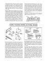
HARD
FACING
WORN
brush each bead before depositing the next Then continue
to fill the groove with short weld beads as before, working
rapidly when depositing and peening the bead Allow plenty
of time for cooling. Examine the casting for cracks that may
develop during cooling periods if any of the beads crack,
chip them out and re-weld If cracking persists, preheat
the entire casting slowly to a dull red heat with an oxyacetylene torch or blow-torch
When the preheated method is
used, the welding can be continuous After completing the
weld, cover the casting with warm dry sand or slaked lime
so it will cool slowly
Malleable iron is ordinary gray cast iron that has been heat
treated to give it a tough ductile outer skin The method of
welding is the same as for cast iron
CUTTltNG
EDGES
DRtHO OFF
WEAVE DEARS
PLOW
SMALLBEARFigure 2
RARD EACIRR
Figure 3
HA_DEACIHR
CULTIVATOR
SHOVEL
SPIKE
HARROW
TOOTH
SOFTBASEMETAL
WEARS
AWAYEASTER
TRAHRAflDFACIDG
/
.'ULTIVATOR
SWEEP
Figure
MILD,STEEL
PATCD
WELDS
Fieure 5
I
Excavating equipment, earth_cutting farm machinery or
others such as plow shares, lister shares, cultivator shovels,
sweeps, subsoilers, spike harrow teeth, tractor treads, excavating buckets, or any surface subject to abrasive action
wil! last much longer and require less sharpening when
their cutting edges are hard faced with hard surfacing
electrodes The arc welding process consists of depositing
a layer of abrasion resisting weld metal on the worn cutting
edges as indicated in red on the parts shown in figure 1
Prepare the part for welding by cleaning the surface to be
welded by grinding it approximately
1-1/2 inches back
from the edge (fig. 2) Position the part so weld metal can
be deposited in the flat position If the material is 1/4_inch
thick or less, use a I/8-inch rod and as low a current as
possible that will still permit the metal to flow out smooth
and fairly thin (1/16 to 1/8-1nch thick) Weave the rod
from side-to-side in a crescent-shaped movement and deposit a bead about 3/4 to 1-1nch wide Several passes
(lald side-by-slde) may be necessary where the worn surfaces are quite wide In some cases a small straight bead
must be deposited along the edge to build it up (fig. 3)
Make beads heaviest where the wear will be greatest, but
avoid excessive build-up as the metal cannot be filed or
machined If shaping is required, heat the weld metal and
forge it. Smoothing and sharpening can be accomplished
by grinding.
For plow and lister shares, cultivator shovels and similar
cutting points, deposit the weld metal on one side only
which will result in a self-sharpenlng edge (fig 4) The
softer base metal on the other side will wear away first and
leave a knlfe-like edge of hard facing material Parts that
must wear uniformly on both sides should be hard faced
on both sides The condition of the worn part must also be
taken into consideration If the part requires a number of
passes to bring it up to the desired thickness, use mild-steel
welding rods first; then cover with deposited metal from
hard surfacing rods If the edge is entirely worn away, a
steel patch (cut to fit) may be welded in place with mild-steel
electrodes, then hard faced (fig 5) To prevent distortion
when hard facing small parts, peen the deposited weld
metal before it cools
1-15
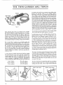
To prepare the torch for use, connect its two cables to the
ground and electrode cables of the welding machine.
Grounding of the work is not necessary as the operation of
the arc flame is entirely independenL With the thumb knob
on the handle in the "off" position, insert two 3/8-inch carbon electrodes in the holders and clamp in place at approximately one-half their length (fig, 2) Do not clamp them
on or near the ends opposite from the arc as this will cause
overheating of the carbons When tightening the clamping
screws, be careful not to apply too much pressure on the
carbons, as they are very brittle and break easily Use only
enough pressure to hold them firmly in place. If the tips
of the carbons do not llne up with each other, an adjustment
may be made by turning the longest of the electrode holders
slightly; too much turning will loosen it, and make it necessary to disassemble the torch to again tighten it properly,
TRUMB KHOB
CARBORELECTRODES
SCREWS
ELECTRODETiPS
CORRECTTO
GROUNDAND:
ELECTRODE
CABLESOF
A C WELDER
Figure
1
Work ordinarily done with a gas weldlng torch is possible
with the twln-carbon arc torch connected to an A.C welder,
The carbon-arc flame is similar to the flame of a gas welding torch in that it provides heat by radiation, rather than
by direct arc between work and electrode, This flame heat
greatly widens the scope of work possible with the arc
welder for brazing, soldering, welding of non.ferrous metals
and localized heaffng for bending, forging and hardening,
The arc torch (fig. 1) consists of an insulated handle wlth
two projecting carbon electrode holders, one of which is adjustable to permit striking and breaking an arc at the carbon
tips. A thumb knob on the handle performs the adjustment
and operates a shut-off switch built into the handle There
are no valves or gouges that require fine adjustment as
with an oxyacetylene torch. The same protective equipment
used for ordinary arc welding is used when operating the
carbon-arc torch.
A wide selection of flame heats may be had by varying
the current and size of the carbon electrodes, Although the
actual temperature of the arc remains the same for any
current setting, the volume of transferable heat increases
with an increase in amperage° However, amperages in
excess of those given below will only cause short carbon life.
1/4-ira carbons ............
5/16-im carbons ..............
3/8-im carbons ...............
30 to 40 amperes
40 to 65 amperes
65 to 90 amperes
Do not make any turning adlustments wl h the s,id ng holder
as this would spoil the contact tension in the switch.
To strike the arc, turn on the welding machine and set it for
approximately 70 amperes Lower the welding helmet and
hold the torch up to silhouette it against the light of a window Slowly move the thumb knob forward until contact
is made between the tips of the carbons. This will start the
arc Then immediately move the knob back to increase the
gap between the carbons The actual distance can be determinecl with a little practice When the carbons are too close
the arc flame will have a sharp crackling noise As the
distance between the carbons is increased, the crackling
will change to o soft purring sound which indicates the best
arc flame There are two heat zones and the small inner
zone is by far the hottest, having an estimated temperature
of 9000 degrees Fahrenheit (fig, 3)
The shape of the flame gleatly influences the way in which
it must be used For example: on beveled work the torch
should be held parallel to the groove so the flame will reach
the bottom (fig 4), If held at right angles to the groove, the
flame straddles the groove and the heat will not reach the
bottom (fig 5). Filler rods, as for gas welding, must be used
on joints of this type.
The soft, bushy flame is pressureless and has no tendency
to blow the mohen metal This is a distinct advantage when
welding thin sheet metal Joints on light material should be
CORRECT
Figure 2
Figure
3
FLAME POSITION
Figure
4
INCORRECT
FLAME
POSITION
Figure
5
,r.,,,,,
1-16
bent and edges fused together by melting down the excess
metal to form a bead (fig 6) No filler rods are required
The carbon-arc torch is ideally suited for brazing and
soldering small tubing+
Cast and malleable iron can be brazed with excellent
results A bronze filler red and common brazing flux are
used Rust, paint or grease must be cleaned from the area
to be brazed If it is a butt joint, such as a crack in a casting,
grind or chip out a beveled groove as for arc welding
Apply the heat from the arc flame gradually by passing
it over the metal surrounding the joint+ When the casting
has become warm, concentrate the arc flame at the joint
The important thing to remember when brazing cost iron
is never to heat the edges of the joint to the melting point
The temperature of the work should not exceed the melting
paint of the filler rod The carbons are held as close to the
work as possible without causlr_g the metal to bubble Hold
the filler rod in the left hand and heat the end of it slightly
by passing it through the arc flame Then dip the heated
end in brazing flux Raise the torch slightly and deposit
some of the flux at the part of the joint being heated. When
the surface of the heated metal takes on a shiny or wet
appearance, the filler rod can be applied
Do not put the rod directly in the flame, but hold it on the
work and let the heat of the edge of the flame and the work
melt the rod Deposit only enough metal to fill the part of +
the joint that has been coated with flux As the metal is
being deposited, move the !orch along the joint slowly,
applying flux to the rod and joint as required
Copper and copper-base alloys such as bronze and brass
may also be brazed, but as their melting temperatures are
so close to the melting point of the filler rod, the process
in many cases becomes one of welding rather than brazing
A bronze filler rod and common brazing flux are used.
Most non-ferrous metals can be welded by manipulating
the torch and filler rod in the same manner as for brazing,
with the exception that the edges of the joint are heated to
the melting point before depositing the filler metar. If the
work is a copper alloy, use common brazing flux If it is an
Figure
6
B
aluminum alloy, use aJumlnum flux The filler rod should
be of the same analysis as the work if regular welding
rod is not available, strips of the parent metal may be used
A back-up strip should be used when welding thin material
Small diameter carbons and low amperage setting are
used for soldering. The torch is held so the work is just within
the visible edge of the flame. Apply the soldering flux and
play the flame over the work until it is just hot enough to
melt the solder. If the joint is to be sweat-soldered, tin the
surfaces to be iolned, then press them together and reheat,
adding mare solder at the edges of the joint
One of the most practical uses of the arc torch is heating
metal for bending, forging, etc, Set the torch for a wide,
enveloping-type flame and apply the heat to the bottom of
the work (fig 7) Since a red heat is not visible through the
dark weldlng glass, the helmet must be raised periodically
so the work can be inspected to avoid overheating To protect the eyes from the rays of the arc, hold the torch to
one side and above your head The carbon-arc torch is
not recommended for welding mild-steeL However, it may
be used for brazing mild-steel if the metal is too thin for
regular metallic-arc welding
CUTTgNG
and
CUTTING
WITH
other
miscellaneous
operations
THE ELECTRIC ARC
\\ \\
Arc cutting is simply the continuation of a "burn through"
such as you probably experienced when practicing with
light sheet-metal welding When this action is accelerated
by using extremely high currents, it becomes an efficient
method of cutting metals Although the edges of the cut
surfaces are not as smooth as when cut with a saw or
oxyacetylene torch, there are many cases where such precision is not required. Ordinary mild-steel welding rods
may be used The current will vary with the type and thickness of the material. In general, high currents increase the
speed of cutting but also increase the rod burn-off rate and
width of the cut
ST_T
CUT
ffEI1E
d,..-MOLT]_H METAL
STEEL
COHTA_HER
F_gure 1
117
BOLT AND
MOVERODUPANO--_.
DOWN
VERTICALLY
_:...,
,_ --' _"
Removing rusty bolts or rivets is an easy job with an electric
arc welder The arc is struck on the head or nut of the bolt
and worked around in a slight circular movement until the
head is completely melted off (fig. 4). A punch is then
used to drive out the remaining part. The bolt or rivet con
be removed by heating the head almost to the melting point,
then quickly shearing it off with a cold chisel Care must be
taken not to cause the bolt to become welded to the metal
_ _'_
START
CUT
HERE
HOLE
PIERCING
Another usefu] application of the welding arc is piercing
holes in metal Coated metallic electrodes ore best far
Figure 2
To make a trlal cut, place a bar of steel approximately
1/4-inch thick on the table so that one end projects over
the edge. Use a 3/32-1nch rod and a current setting of
around 140 amperes HoJd the rod as shown in figure 1 and
strike an arc on the tap corner at the edge of the bar where
the cut is to be made, Feed the rod into the molten puddle
and keep the crater burning through as the rod is moved
across the bar. To catch the molten metal, place a metal
container on the floor directly under the cut
When cutting metal heavler than 1/4-1nch, the arc is started
at the bottom corner and worked up and down vertically
as shown in figure 2, advancing the bottom of the cut
slightly ahead of the top of the cut to permit molten metal
to run out more easily_ if a smooth edge is desired, the
pieces can be ground on an abrasive wheel. Electrodes
designed especially for cutting may also be used_
REMOVING
RIVET CUTTING
SEAMS
In addition to cutting, the electric welding arc can be used
for beveling the edges of material to be welded, gouging
out cracked welds for rewelding or removing tack-welds.
The surface of the metal being worked upon should be approximately in the vertical position, or tipped slightly toward
the arc (flg_ 3)_Start at the bottom of the seam to be gouged
out and work upward. The rate of speed will depend upon
the depth of the groove and the amount of metal removed.
this purpose because of their small size and insulation
afforded by the coatlng_ The process is extremely fast and
a surprisingly clean circular hole can be made For practice,
place a piece of scrap iron 1/4-inch thick (or less) on the
table and allow it to project over the edge as for arc
cutting Use a 3/32-1nch rod and the same current as for
cutting_ At the place where the hole is to be pierced, strike
an arc and hold it until a molten puddle is formed_ Then
push the electrode down against the molten puddle and
force it through the plate_ It is possible to hold the electrode
against the melted plate because the metal core meffs off
faster than the coating_ The coating (not the rod) touches
the molten metal (fig 5) 1"he gap maintained by the protruding coating prevents the metal core of the electrode
from sticking or freezing to the plate
if a larger diameter hole is desired, first pierce a hole as
described. Then, holding o fairly long arc, melt the edges
of the hole away by moving the rod around it (flg_ 6). Holes
of almost any diameter can be mode_ To pierce a hole
through material thicker than 1/4_inch, work from the
underside
HEATING
The carbon arc provides a convenient method for localized
heating of aJI metals. S_mply strike an arc on the part to be
heated and "play" it across the surface until the required
temperat_ure is reached
GQUGIRG
Figure 3
!-18
Figure 4
Figure 6
mNERT-GAS
METAL-ARC
WELDING
(Nonconsumabne)
GROUNDED
WORK
PIECE
ANYCRAFTSMAH
WELDER
ALLCABLES
ORWORK
TABLE
MAYBEUSED
WiTHHF,
SHOULD
BE
/
ATTACHMENT
KEPT
SHORT TOELECTRODE
/
ASPOSSIBLE HOLDER
/
GROURB
CLAMP
(Donotexceed12-f/2
feet[nlength)
[]
D
O_
_/\
K.F.ATT
GROUND
CABLE I
WELDER
GROUND
o
o
CABLE
_,,o
g
230VOLT
_=========E_6O
CYCLE
SINGLE
PHASE
WELDING
CABLE
TO WELDER
HiGHFREQUENCY
ATTACHMENT
Figure I
HIGH
FREQUENCY
ATTACHMENT
The Craftsman, High-Frequency Attachment may be used
with any Craftsman welder or other single-phase, transformer_type welder of high quality construction having an
AC, or AC/DC power output Tungsten inert gas (T.LG.)
welding has many useful and advantageous applications
as described in the following paragraphs_ In order to use
the T.LG. process with an AC welder, a high-frequency
attachment must be provided_ Figure 1 shows a typical
hookup using this high-frequency attachment with a Craftsman welder_ When not using the TJ.G, welding process, the
high-frequency
attachment also permits easy "arc" start.
ing and greatly improved results with many hard-to-weld
rods (low hydrogen rods) as well as making the welding
operation much easier to perform.
The use of a hlgh-frequency attachment makes possible the
establishment of an arc without touching the electrode to
the work., Once the arc has been established, it isstabilized
by the hlgh-frequency output_ This is essential in the T.I.G.
process in order to avoid contaminating the tungsten electrode or the work..
PRINCIPLES
OF OPERATION
The necessary heat for inert-gas welding (nonconsumable)
is produced by an electric arc maintained between the nonconsumable electrode and the work-piece. The electrode
used for carrying the current is usually a tungsten or tungsten
alloy rod_ The heated weld zone, the molten metal and the
nonconsumable electrode are shielded from the oxidizing
effects of the atmosphere by a blanket of inert gas fed
through the TJ_G. torch and the weld is made by applying
the arc heat until the abutting edges of the work-places are
melted, adding filler rod if necessary_ The resultant pool
of molten metal, upon solidifying, joins the edges of the
members togethen The process may also be used for adding
metal to surfaces, Iocally-meltlng and spot-joinlng parts.
A thorough cleaning of the surface to be welded isrequired_
WELDER
CABINET
MUSTBE
GROUNDER
ACORDOWELDER
Figure 2
Alloil, grease, paint, rust, dirt or other contaminants must
be removed either by mechanical means or by the use of
vapor or liquid cleaners, Files, chisels and stainless wire
brushes may be used Grinding is not recommended, Liquid
cleaners such as naphtha, mineral spirits, alcohol, acetone
and methyl-ethyl-ketone can be used All surfaces must be
wiped dry with a clean cloth, Cleaners should not be used
after a joint is assembled prior to welding,
Striking the arc may be accomplished
as follows:
1_ Touching the electrode to the work momentarily and
quickly withdrawing it a short dlstance_ (DC power source)
2 Use of an apparatus which will cause a spark to jump
without touching the electrode to the work. (AC power
source with high-frequency unit attachment)
The high-frequency
arc stabilizer provides for this latter
method of starting the arc. Such devices are not required
with DC, consequently it is usually necessary to touch the
electrode to the work to start the arc.
For manual welding, once the arc is started, the electrode
holder is held with the electrode positioned at an angle of
about 75 degrees to the surface of the weld puddle as
shown in figure 2 To start the welding, the holder is usually
moved in a small circle until a pool of molten metal of suitable size is obtained. Once adequate fusion is achieved at
any one point, a weld is made by gradually moving the
electrode along the parts to be welded to melt the adjoining edges progressively, adding filler rod as required.
Solidification
of the melted metal follows progression of
the arc along the joint and completes the welding cycle_
Material thickness, joint design and weld characteristics
desired will determine whether or not filler metal should
be added to the joints_ When filler metal is added during
manual welding, it is applied by hand feeding the filler rod
(from the side) into the pool of molten metal in the region
of the arc. Filler rod is added in essentially the same manner
when welding by the oxyacetylene method.
1-19
THE PUDDLE
DIRECTION
(1)
DEV_.LOP
OF WELD"._
(2) MOVE
(3) ADD
TORCH
TILLERMETAL
'_
_,/,//////////,',/,/,,'/,,////,,/
_/27_
_///I/I///f////////////J
f
WOREPIECE
(5) MOVETORCH
TO LEADING
EDGE_
(4) REMOVE
ROD
OT
POD L
/7
ADDITION
OF
FILLERMETAL
(VERTCAL
POSITIO_
-_s°'_
I
_////////////_;///////////_/_
Figure
3
The filler rod is usually held at an angle of approximately
15 degrees to the work and slowly fed into the weld puddle.
One of the most commonly used techniques for feeding filler
rod is shown in figure 3. Another method, used most often
in multlple-pass welding of vee joints, is to press the filler
rod into the vee groove in line with the weld and melt it
along with joint edges_ Still another method, used frequently in making large welds, is to feed filler metal continuously into the weld puddle by oscillating the filler rod
and arc from one side of the weld to the other° The filler
rod moves in one direction while the arc moves in the
opposite direction, but the filler rod is at all times in close
proximity to the arc and feeding into the weld puddle.
electrodes are alloyed with small percentages of thorium
or zirconium. Such electrodes have the advantage of greater
current-carrying
capacity for a given diameter, a more
stable arc at low current values, and longer life with less
deposit of tungsten in the welds.
TYPES OF GAS
TO USE
Either argon, helium, or a mixture of the two can be used with
the T.I.G process. Argon is used most frequently because:
1. It provides general
metals
suitability
with a wide variety
of
2. It maintains a stabilizing influence on the welding arc.
Joints may be welded by the T.I.G process include all
standard types, such as square abutting edge, vee butt, tee
and lap connections, It is seldom necessary to bevel edges
of material 1/8-1nch or less, although heavier materials are
usually beveled. Whenever joints are beveled, filler material must always be added_
3_ It costs less (due to the lower flow rates required).
The accompanying tame provides a guide to the type of
current recommended for welding some typical materlals.
Electrodes used for the T.I.G. (nonconsumable) process may
be pure tungsten or tungsten aBoy. Pure tungsten electrodes
were formerly used exdusively_ At this time, however, many
Argon is generally supplied in K-cyllnders, having a capacity
of approximately 238 cubic feet at a pressure of 2200 psi,
or in T-cylinders, having a capacity of approximately
330
cubic feet at a pressure of 2640 psi. Purity of commercial
argon ranges between 99,95% and 99_99%
Helium is generally used when welding heavy metal sections
because it provides greater weld penetration. Mixtures of
argon and helium are useful when a balance of these characteristics is desired_
Matetla]
CurrentSelectionfor Inert-gas
(nonconsumable)
welding
Magnesium
up to _i_-imthick
Magnesium
above_'iG.in thick
Magnesium
castings
AIuminumup to _32.in thick
Aluminumover_-in
thick
Aluminumcastings
Stainlesssteel
Brass alloys
iliconcopper
;liver
Higb-chlomium,
nickelbase,high.
temperaturealloys
Silver cladding
Hard facing
Cast iron
Lowcarbonsteel, O015 to 0 030 int
Lowcarbonsteel, 0.030 to 0.125 in.
High.carbonsteel, 0015 to O,O30in
High.carbonsteel, 0030 in andup
DeoxidizedcopperP
*Where aIternating current _s recommended as a second choice, use about 25%
recommended fat DCSP,
t Co no use _lte nang cu rent on tigEhlly jigged p_rts.
Use brazing flux or sl con-bronze _x
o_ /4, nch and h ck_
1-20
higher current than that
WELDgNG
RGD
AWS
E-6Gll
$PEC FmCATmONS
MILD
STEEL
AC-DC
GENERAL APPLICATIONS:
Farm Equipment
o Sheet Metal o Car and Truck •
Body and Fender = Pipe o Tanks o Maintenance o Jigs and Fixtures o Cabinets
o General Repairs oStructuralSteel
SIZES AND HEATS
Diameter
....
Flat
Vertical
Overhead
1/16"
3/32"
20"55
20"55
20-55
20-80
20"65
20"B5
1/8"
75"130
75"115
75"115
(AMPS)
5132"
100-175
100-t50
100-150
3/16"
t50-225
150-200
7132""
175-250
t/4'*
200-375
SPECl FICATIONS
MEETS
THESE
REQUIREMENTS _'
AmericanWelding Society .....................
Military .......................................
American Bureauof Shipping ..............
Physical Properties of Deposited Metal:
Tensile Strength
Yield Point
As Welded
..........................................
70,000 to 75,000 psi
60,000 to 65,000 psi
..........................................
% Elongation in 2-inches
Reduction
in Area
Class:E-6011
MIL-E-15599C
Class:E-5011
....................................
23% to 25%
.....................................
50% to 55%
Stress Relieved
65,000 to 70,000 psi
55,000 to 60,000 psi
30% to 35%
65% to 75%
DESCRIPTION
The AWS E-6011 is an AC-DC (reverse polarity) electrode with a special coating that provides strong
fluxing action for high quality welds, even in dirty, rust covered, galvanized or plated steels, An extremely
stable, spray type penetrating arc, is produced that is easy to start and restart after interruption.
It is a
versatile electrode, producing welds far beyond the requirements of its A.WS. classification It adapts to a
wide variety of jobs due to the wide range of amperage settings at which top quality results are obtained
Features:
Deeper
Penetration
-
Fast-Freeze
Puddle -
Greater
Arc Stability.
WELDING PROCEDURE: Weld with AC or DC (reverse polarity) Strike the arc by brushing rod tip lightly
at the point where weld is to be made. After the arc is established and weld material is deposited,
concentrate on holding a short arc that is just long enough to keep the electrode from touching the molten
metal, In the flat position, use a slight oscillating motion as you advance, In vertical position, on sheet steel
start at the top of the seam and weld down, This provides a more rapid speed of travel, lower penetration,
and minimum warpage When welding overhead use a straight stringer bead or a circular motion Keep the
molten pool as small as possible_ Use small electrodes overhead, none larger than 5/32 diameter_
2_1
AWS
E-6013
MBLD
multi-purpose
STEEL
AC-DC
all position
GENERAL APPLICATIONS:
Farm Equipment
o Car and Truck
o Sheet Metal o
Pipe o Tanks e Boilers = Structural Steel o Maintenance Repairs o General Repair
Work
SIZES AND
Diameter
5/64'"
20-55
20-55
20-55
......
Fiat
Vertical
Overhead
3/32"
20-75
20-65
20_65
HEATS (AMPS)
118"
75-130
75-115
75-115
5/32"
100-175
100.150
100-150
3/16"
150-225
150-200
1/4"
200"375
SPECl FICATIONS
MEETS
THESE
REQUIREMENTS _)
Physical Properties
Military ................................................
mericanWelding Society ....................
MIL-E-15509C
Class:E-6013
& MI
L-E-S043A
American Bureauof Shipping ...................
Class:E-0013
of Deposited
Metal:
TensileStrength ......................................................
Yield Point ................................................
% Elongation in 2-inches ......................................
Redaction in Area .................................................
As Welded
75,000 to 00,000 psi
62,000 to 07,000 psi
20% to 29%
40% to 55%
Stress Relieved
05,000 to 70,000 psi
50,000 to 00,00g psi
27% to 35%
00% to 70%
DESCRIPTION
The AWS, E-6013 is a general purpose mild steel electrode for use with AC or DC It produces a very stable,
easily handled arc throughout a wide amperage range_ The moderately penetrating and easily directed arc
provides excellent results in all positions (fiat, vertical or overhead) and is ideal for single pass horizontal
fillet welds_ Spatter loss is low, as the weld metal solidifies quickly producing a closely rippled deposit with
good appearance.
Even though it is designed for production
welding in mild
multi-purpose use where sound durable welds are required,
steel fabrication,
this rod is excellent
for
The arc is easily started, even at low amperage settings for light gauge steel, yet is stable at the high
amperages needed for higher welding speeds, and for heavier sections.
Use with AC or DC (see recommended amperages) Hold a short arc, just long enough to keep the electrode
from touching the molten metal. In flat position single pass fillets or butt welds may be made with or
without weaving. Weld from bottom up on vertical welding of heavy sections Welding down on light
material or fillets produces excellent results Use 5/32-inch or smaller electrodes for overhead work, making
either stringer or weaving beads.
2-2
WELDWNG
ROD
HARD
SPECIJFICATiONS
SURFACING
medium
chrome-carbon
AC-DC
electrode
GENERAL APPLICATIONS:
Tractor Grousers and Rollers o Scraper Blades o Agricultural Implements o Plow Shares o Hitches • Power Shovel o Dipper Teeth and
Drive Sprockets = Coal Cutters e Conveyor Rolls • Mining Buckets • Rock Crushers
o etc,
SIZES AND HEATS
Diameter ....
3/32"
1/8"
_
5/32"
Amperes
55-85
100-130
1
130-150
(AMPS)
3/10"
175-200
7/32"
1/4"
175-250
225-275
SPECl FICATIONS
THESE
MEETS
REQUIREMENTS
Military .................................
Physical Properties of De_positedMetal
As Welded Condition (Rockwell "C" 46-50)
After Cold Working (Rockwell "C" 50-54)
MIL-E-19141C
....................................................
.............................................
450-500 Brinell Hardness
500-550 Brineli Hardness
DESCRIPTION
The Medium Chrome-Carbon rod is a hard-surfacing alloy steel electrode with a coating of powdered metals
and flux. When welding, this special coating combines in the arc with the steel core wire to give an
extremely
hard weld-meta! deposit
Deposited weld metal requires no heat treatment for maximum
strength, ductility, and wear resistance, Annealing or heat treating will not soften the metal deposit, which
is not machinable, but may be hot forged to any desired shape, Deposited metal has a very fine grain and is
free of slag and porosity The metal is tough and highly resistant to wear and impact
The rod is designed for use with either AC or DC (either polarity) Hold a medium short arc and deposit the
metal with a weaving motion Excellent welding results are obtained in either the vertical or flat position,
WELDING PROCEDURE: Gdnd the surface to clean and remove shallow cracks, rust, or other foreign
material Cracks too deep to be removed by grinding should be gouged out w_th a cutting torch or cutting
rod Use the "drag" technique to deposit weld metal, to thin edges when desirable or weave a wider bead,
or use a "free" arc,
2-3
WELDmNG
AWS
ROD
E-7014
SPECmF CATmONS
CONTACT
for welding
GENERAL
Fabrication
Fabricating
Welding
of mild
AC-DC
steel
APPLICATIONS:
Sheet Metal Fabrication and Repairs
e Machinery
• Construction
Equipment Repairs = Storage Tanks
e Shipbuilding
Structural Shapes and Heavy Equipment
= Equipment and Heavy Pipe
SIZES AND HEATS
Diameter ....
1/18"
Length
Amperes
12"
70-90
3/32"
14"
90-110
lAMPS)
1/8"
14"
130-105
5/32"
14"
190-210
3/16"
1/4"
18'"
200-250
18"
250-350
SPECl FICATIONS
MEETS _k
THESE _)
REQUIREMENTS JV
Physical
Properties
AmericanWelding Society .....................
American Bureauof Shipping ................
of Deposited
Class:E-7014
C/ass:E-7014
Metal:
TensileStrength ...................................................................................
Yield Point .....................................................................................
% Elongation in 2.inches ..........................................................................................
AsWelded
72,000 psito 78,000 psi
60,000 psito 69,000 psi
17%to 28%
DESCRIPTION
The AWS E-7014 is an excellent electrode for the inexperienced or experienced welder_ Starts on contact
with smooth surge-free arc, also restrikes instantly. This Craftsman electrode has powdered iron in the
coating which makes welding easier and faster_ The slag is easy to remove in most cases self-peeling as the
weld cools_
Ideal for fixture welding where weld appearance and lack of spatter is important.
permits use in all welding positions
The amount
of slag
WELDING PROCEDURES: Weld materials should be clean. Best results are obtained when fit-up is good.
Either AC or DC current may be used. When arc is established, deposit metal holding a short arc or place
electrode in contact with work,.
2-4
Jm=LDBNG
ROD
SPECNF CAT ONS
MACHINABLE
CAST
machineable
GENERAL APPLICATIONS:
Castings o Gears o Sprockets
AND
3/32"
48-85
Amperes
AC-DC
on all cast irons
Cylinder Blocks o Crankcases o Valve Seats e Defective
e Casting Repairs in General o Garages o Farms o Shops
SIZES
Diameter
welds
RON
HEATS
(AMPS)
1/8"
75-130
5/32"
100-150
3/18"
130-175
DESCRIPTION
This electrode uses a nickel core wire, and produces a fully machinable weld without
pre-he._ting the casting, Cast irons can be joined to steel, nickel alloys and copper,
This electrode
characteristics
operates with
It is recommended
AC or DC (reverse polarityL
for automotive
repairs,
such as cylinder
and other cast iron parts In maintenance
many farm machinery
parts
and repairs
It has very stable arc
blocks,
crank
cases, valve seats
it is used on gears, sprockets,
and
WELDING PROCEDURE: Remove all dirt and grease from work piece before starting to
weld, A cutting electrode may be used to burn a groove along the break where the weld is
to be made This cutting electrode removes the grease and scale, and then seals in any oil
soaked into the cast iron
Use the lowest amperage that gives good fusion
relieve strain and stress
CUTTIING
quick,
GENERAL
inexpensive,
APPLICATIONS:
Cutting
During cooling, peen hammer the weld to
ROD
easy
AC-DC
cuts through
all metals
e Piercing _ Gouging = Scarfing o Beveling = etc
SIZES AND HEATS (AMPS)
Diameter ......
Amperes- AC
3/32"
80150
1/8"
75-130
Amperes - DC
150-250
-
100o150
5/32"
3/16"
130-175
DESCRIPTION
For piercing, gouging, cutting,
and scarfing
Excellent
for removing
old welds in preparation
to rewelding_
Also used for beveling
cracks in castings or removing
sharp edges prior to welding
Needs no oxygen or special
equipment
to cut
carbon
steels,
stainless
steel, manganese
steel, cast iron, etc
Recommended
for the owners of all arc welders_ AC or DC
WELDING PROCEDURE: Place etectrode in holders so that it's positioned like a lance in
the direction of travel The angle between the electrode and work metal should not
exceed 15° Strike arc at starting point, Push electrode along the line of cut, forcing the
molten metal ahead and away If deeper gouge is required, repeat procedure untg the
desired depth has been reached
2_5
REPAIR PARTS
PARTS LIST FOR CRAFTSMAN
43 27 45
42
230 AMP WELDER
MODEL
113o201372
15
45
34
41
\
27
\
44
\
/
35
11
32
\
\
10
23
24
27
13
\
12
=
29
28
2-6
Transformer
not replaceable°
19
PARTS LIST FOR CRAFTSMAN
230 AMP WELDER
MODEL
113.201372
Always Order by Part Number - not by Key Number
Key
No.
1
2
3
4
5
6
7
Part
No.,
61331
61276
61277
STD 511110
61278
61279
!60325
8
9
10
11
12
13
14
15
16
17
18
19
20
21
22
61280
STD 611005
STD 541025
23
24
25
61314
61302
STD 501102
26
27
61315
STD 551108
STD 551225
STD 551025
STD 541006
30307
61143
61332
61335
STD 601103
61333
61334
61384
o
Description
Plate, Selector
Spacer
Pointer
*Screw, Pan Hd 10-32 x 7/8
Knob Assembly
Bushing
Washer, 3/8 x 1-3/8 x 3/64
Cabinet, ]'op
*Screw, Type AB Pan Hd No 10 x 1/2
*Nut, Hex 1/4-20
*Lockwasher, 1/4 int..
*Washer, 17/64 x 47/64 x 1/16
*Nut, Hex 6-32
Connector, Cable
Cord
Slide, Shunt
Bracket, Guide
*Screw, Ty T Pan Hd 10-32 x 3/8
Guide, Shunt
Spring
Core Assembly, Moving
Transformer Assembly
Motor
Bracket, Fan
*Screw, Socket Set 10-32 x 1/4
Blade Assembly, Fan
Lockwasher, #8
I(ey J
Part
No.. i
No_
r
28 130284
29
30
31
32
33
34
35
36
37
36
39
40
41
42
43
44
45
46
47
48
49
50
51
52
-
51439
_STD 522507
61234
6TD 601105
60314
STD 510607
61295
30332
61171
61086
61329
STD 510692
STD 600805
30254
STD 551008
STD 551010
STD 541008
60309
61115
61116
61117
6TD 541110
STD 551110
61186
61298
61337
Description
+Holder, Electrode
+Clamp, Work
*Screw, Hex Hd, 1/4-20 x 3/4
Cable Assembly, Work
*Screw, Ty T Pan Hd 10-32 x 1/2
*Screw, Truss Hd.. I/4-20 x 5/8
*Screw, Pan Hd 6-32 x 3/4
Cable Assembly, Electrode
insulator, Plug
Plug, Selector
Relief, Strain
Cabinet, Bottom
*Screw, Pan Hd. 6-32 x 3/16
*Screw, Pan Hd. 8-32 x 1/2
Switch
*Washer, 3/16 x 3/8 x 1/32
*Washer, 13/64 x 5/8 x 1/32
*Nut, Hex 8-32
Washer, 1-1/64 x 1-1/2 x 1/64
Block, Contact Mounting
Contact, Selector Plug
B_ock, Contact Mounting
*Nut, Hex 10-32
*Lockwasher, No 10
+Helmet
Bag Assembly, Loose Parts
Owners Manual (not illustrated)
*Standard Hardware Item - May be Purchased Locally,
+Stock Item - May be secured through the hardware department
Sears Retail Stores or Catalog Order Houses,
of most
OTransformer not replaceable,
_7
ISears I
230 AMP
DUAL
RANGE
ARC WELDER
SERVICE
MODEL NO.
113.20137 2
HOW TO ORDER
REPAIR
PARTS
Now that you have purchased your 230 amp arc welder, should
a need ever' exist for' repair parts or service, simply contact any
Sears Service Center and most Sears, Roebuck and Co. stores.
Be sure to provide all pertinent facts when you call or visit
The model number' of your 230 amp arc welder will be found
on a plate attached to your' welder, at the rear' of the cabinet.
WHEN ORDERING
REPAIR
FOLLOWING
INFORMATION:
Part No 61337
ALWAYS
GIVE
PART NUMBER
PART DESCRIPTION
MODEL NUMBER
113,201372
NAME OF ITEM
230 AMP ARC WELDER
All parts listed may be
and most Sears stores.
locally, your order will
Repair Parts Distribution
Sold by SEARS,
PARTS,
ROEBUCK
AND
ordered from any Sears Service Center
If the parts you need are not stocked
be electronically
transmitted to a Sears
Center for handling.
CO., Chicago,
Form No SP4271-4
THE
IL 60684
U.S.A.
Printed in USA
6/81