Download Santerno SUNWAY M XS User manual

Transcript
• 15P0177B100 •
SUNWAY M XS
2200TL – 3000TL – 3800TL
SINGLE-PHASE SOLAR INVERTER
USER MANUAL
-Installation and Programming InstructionsIssued 10/04/2012
R.00.1
Inverter Software Version: 1.055
Display Software Version: 1.3.3
•
•
•
•
•
•
•
•
This manual is integrant and essential to the product. Carefully read the instructions contained
herein as they provide important hints for use and maintenance safety.
This device is to be used only for the purposes it has been designed to. Other uses should be
considered improper and dangerous. The manufacturer is not responsible for possible damages
caused by improper, erroneous and irrational uses.
Elettronica Santerno is responsible for the device in its original setting.
Any changes to the structure or operating cycle of the device must be performed or authorized by
the Engineering Department of Elettronica Santerno.
Elettronica Santerno assumes no responsibility for the consequences resulting by the use of nonoriginal spare-parts.
Elettronica Santerno reserves the right to make any technical changes to this manual and to the
device without prior notice. If printing errors or similar are detected, the corrections will be included
in the new releases of the manual.
The information contained herein is the property of Elettronica Santerno and cannot be reproduced.
Elettronica Santerno enforces its rights on the drawings and catalogues according to the law.
All the names and marks mentioned in this manual are the proprietary of their respective owners.
Elettronica Santerno S.p.A.
Strada Statale Selice, 47 - 40026 Imola (BO) Italy
Tel. +39 0542 489711 - Fax +39 0542 489722
santerno.com [email protected]
SUNWAY M XS
2200 TL
3000 TL
3800 TL
INSTALLATION AND
PROGRAMMING INSTRUCTIONS
SUNWAY M XS 3000TL
0. TABLE OF CONTENTS
0. TABLE OF CONTENTS............................................................................................ 3
0.1. INDEX OF FIGURES ............................................................................................... 5
0.2. INDEX OF TABLES.................................................................................................. 7
1. SCOPE OF THIS MANUAL ...................................................................................... 8
2. GENERAL INFORMATION ...................................................................................... 8
2.1. DESCRIPTION OF THE PRODUCT ........................................................................ 8
2.2. BENEFITS ............................................................................................................... 8
2.3. OPERATING PRINCIPLE ........................................................................................ 9
2.4. MAIN STANDARD INTEGRATED FUNCTIONS ...................................................... 9
2.5. ATTACHED DOCUMENTATION............................................................................ 10
3. BASIC INSTALLATION ...........................................................................................11
3.1. CAUTION STATEMENTS ...................................................................................... 11
3.2. CHECKING THE PRODUCT ON DELIVERY ......................................................... 13
3.2.1.
DATAPLATE ............................................................................................................................ 14
3.3. TRANSPORT AND HANDLING ............................................................................. 17
3.4. INSTALLATION...................................................................................................... 19
3.4.1.
ENVIRONMENTAL
REQUIREMENTS
FOR
THE
EQUIPMENT
STORAGE,
INSTALLATION AND OPERATION ....................................................................................... 19
3.4.2.
WALL MOUNTING .................................................................................................................. 20
3.4.3.
ELECTRICAL CONNECTION ................................................................................................ 23
3.5. COMMISSIONING ................................................................................................. 34
3.5.1.
STOPPING THE INVERTER .................................................................................................. 35
3.6. QUICK CONFIGURATION ..................................................................................... 36
3.6.1.
SETTING THE LANGUAGE ................................................................................................... 36
3.6.2.
SETTING THE COUNTRY ..................................................................................................... 37
3.6.3.
SETTING THE TIME ZONE.................................................................................................... 38
3.6.4.
SETTING THE DATE AND TIME ........................................................................................... 39
3.6.5.
SETTING THE CURRENCY................................................................................................... 41
3.6.6.
SETTING THE FEED-IN TARIFF ........................................................................................... 42
3.6.7.
RESETTING THE HISTORY DATA ....................................................................................... 43
3.6.8.
RESETTING THE DISPLAY ................................................................................................... 44
3.7. CONNECTIVITY .................................................................................................... 45
3.7.1.
WI-FI CONNECTIVITY ............................................................................................................ 45
3.7.2.
ACCESSING THE INVERTER DATA .................................................................................... 49
3.7.3.
SUNWAYPORTAL.IT .............................................................................................................. 51
3.7.4.
TECHNICAL SUPPORT ......................................................................................................... 52
3.7.5.
CONNECTIVITY TROUBLESHOOTING............................................................................... 53
3.8. DATALOGGING ..................................................................................................... 54
4. GRAPHIC INTERFACE MODULE ...........................................................................55
3/124
SUNWAY M XS 3000TL
INSTALLATION AND
PROGRAMMING INSTRUCTIONS
4.1. NAVIGATING IN THE GRAPHIC INTERFACE ...................................................... 56
4.1.1.
NAVIGATION BAR .................................................................................................................. 58
4.1.2.
MENU AREA ............................................................................................................................ 58
4.1.3.
STATUS BAR AREA ............................................................................................................... 58
4.2. DISPLAY WINDOWS AND DATA ENTER WINDOWS .......................................... 61
4.2.1.
GRAPH WINDOW ................................................................................................................... 61
4.2.2.
ALPHANUMERIC KEYPAD WINDOW .................................................................................. 62
4.2.3.
LIST WINDOW ......................................................................................................................... 63
4.2.4.
COMMAND EXECUTION WINDOW ..................................................................................... 63
4.3. DESCRIPTION OF THE MENUS ........................................................................... 64
4.3.1.
ORGANISATION OF MEASURES AND PARAMETERS.................................................... 65
4.3.2.
INFO MENU ............................................................................................................................. 67
4.3.3.
GRAPH MENU ......................................................................................................................... 74
4.3.4.
CONNECTIVITY MENU .......................................................................................................... 76
4.3.5.
TOOLS MENU ......................................................................................................................... 80
4.3.6.
ALARMS MENU....................................................................................................................... 98
4.3.7.
STATUS MENU .....................................................................................................................111
4.3.8.
WARNINGS ............................................................................................................................113
4.3.9.
WI-FI STATUS MENU ...........................................................................................................114
5. ADVANCED INSTALLATION ................................................................................116
5.1. SERIAL COMMUNICATIONS .............................................................................. 116
5.1.1.
GENERAL ..............................................................................................................................116
5.1.2.
DIRECT LINKING ..................................................................................................................116
5.1.3.
CONNECTION .......................................................................................................................116
5.1.4.
COMMUNICATIONS PROTOCOL ......................................................................................117
5.1.5.
SPECIFICATIONS OF THE SERIAL COMMUNICATIONS ..............................................117
5.2. USB CONNECTION ............................................................................................. 118
5.3. GRID INTERFACE PROTECTION AUTOTEST ................................................... 118
5.4. MAINTENANCE ................................................................................................... 120
5.5. REMOVING THE INVERTER............................................................................... 121
6. SPECIFICATIONS .................................................................................................123
4/124
INSTALLATION AND
PROGRAMMING INSTRUCTIONS
0.1.
SUNWAY M XS 3000TL
Index of Figures
Figure 1: Block diagram of the SUNWAY M XS ................................................................................................ 9
Figure 2: Packaging of the SUNWAY M XS .................................................................................................... 13
Figure 3: Dataplates of the SUNWAY M XS.................................................................................................... 14
Figure 4: Label placed on the metal enclosure of the product ........................................................................ 16
Figure 5: Procedure for opening the package ................................................................................................. 17
Figure 6: Procedure for removing the SUNWAY M XS from its packing ......................................................... 18
Figure 7: SUNWAY M XS box with packing elements .................................................................................... 18
Figure 8: Minimum clearance (in mm) to respect for proper ventilation of the SUNWAY M XS ..................... 21
Figure 9: Detail of the SUNWAY M XS bracket with the fixing screws ........................................................... 21
Figure 10: The SUNWAY M XS in upright position ......................................................................................... 22
Figure 11: Detail of the SUNWAY M XS with the side handles ....................................................................... 22
Figure 12: Removing the cable cover .............................................................................................................. 23
Figure 13: SUNWAY M XS connectors ........................................................................................................... 24
Figure 14: Fixed element of the grid connector ............................................................................................... 26
Figure 15: Flying connector for the connection to the grid .............................................................................. 26
Figure 16: Mounting the floating connector for the connection to the grid ...................................................... 27
Figure 17: Polarity for string connection to the main PV field and DC-side disconnect switch ....................... 30
Figure 18: Removing the protective film from the touchscreen display........................................................... 32
Figure 19: Slots for the application of the fiscal seal ....................................................................................... 33
Figure 20: Example of the Start Menu ............................................................................................................. 34
Figure 21: Language setting page ................................................................................................................... 36
Figure 22: Setting the dialogue language ........................................................................................................ 37
Figure 23: Country setting page ...................................................................................................................... 37
Figure 24: Setting the Country ......................................................................................................................... 38
Figure 25: Name of the Country displayed in the start menu .......................................................................... 38
Figure 26: Time zone setting page .................................................................................................................. 39
Figure 27: Setting the time zone ...................................................................................................................... 39
Figure 28: Setting the date .............................................................................................................................. 40
Figure 29: Setting the date .............................................................................................................................. 40
Figure 30: Setting the currency ....................................................................................................................... 41
Figure 31: Setting the currency ....................................................................................................................... 41
Figure 32: Net metering setting page .............................................................................................................. 42
Figure 33: Setting the feed-in tariff .................................................................................................................. 42
Figure 34: History data resetting page ............................................................................................................ 43
Figure 35: History data resetting page ............................................................................................................ 43
Figure 36: Display resetting page .................................................................................................................... 44
Figure 37: Resetting the display ...................................................................................................................... 44
Figure 38: Inserting the Wi-Fi transmitter ........................................................................................................ 45
Figure 39: Activating the Wi-Fi connection ...................................................................................................... 45
Figure 40: Setting the AD HOC connectivity ................................................................................................... 46
Figure 41: Setting the ROUTER connectivity .................................................................................................. 47
Figure 42: Selecting the desired network ........................................................................................................ 47
Figure 43: Setting the network access password ............................................................................................ 47
Figure 44: IP address assignment mode ......................................................................................................... 48
Figure 45: Setting the IP address .................................................................................................................... 48
Figure 46: Setting the subnet mask ................................................................................................................. 48
Figure 47: Setting the gateway ........................................................................................................................ 49
Figure 48: Setting the DNS .............................................................................................................................. 49
Figure 49: Icon of the SUNWAY M XS application on the iPhone .................................................................. 51
Figure 50: Activating the Sunwayportal.it service ............................................................................................ 51
Figure 51: Activating the Technical Support Service ....................................................................................... 52
Figure 52: Checking the Technical Support Service ....................................................................................... 52
Figure 53: Displaying a measure graph........................................................................................................... 54
Figure 54: Graphic interface module/Touchscreen display – Start menu ....................................................... 55
Figure 55: Screens of the graphic interface module at power on .................................................................... 56
Figure 56: Start menu ...................................................................................................................................... 56
Figure 57: Example of a screen ....................................................................................................................... 57
Figure 58: Screen of the Alarms menu ............................................................................................................ 58
Figure 59: Screen of the Wi-Fi Status menu ................................................................................................... 59
5/124
SUNWAY M XS 3000TL
INSTALLATION AND
PROGRAMMING INSTRUCTIONS
Figure 60: Screen of the inverter Status menu ................................................................................................ 60
Figure 61: Example of a measure graph ......................................................................................................... 61
Figure 62: Example of an alphanumeric keypad window ................................................................................ 62
Figure 63: Example of a list window ................................................................................................................ 63
Figure 64: Example of a Run Command window ............................................................................................ 63
Figure 65: Icons of the Menu Area in the start menu ...................................................................................... 64
Figure 66: Info menu tree ................................................................................................................................ 67
Figure 67: Graph menu.................................................................................................................................... 74
Figure 68: Selection page for the measure to be graphically displayed .......................................................... 74
Figure 69: Steps to take for the customization of the measures to be graphically displayed ......................... 75
Figure 70: Setting page of the Default View .................................................................................................... 75
Figure 71: Setting the Graph menu as the Default View ................................................................................. 76
Figure 72: Connectivity menu tree ................................................................................................................... 76
Figure 73: Tools menu tree ............................................................................................................................. 80
Figure 74: Tools menu, Customization submenu ............................................................................................ 83
Figure 75: Tools menu, Advanced Configuration Submenu............................................................................ 85
Figure 76: Tools menu, Advanced Configuration > Inverter ............................................................................ 87
Figure 77: Tools menu, Advanced Settings > Grid submenu.......................................................................... 88
Figure 78: Example of an alarm screen........................................................................................................... 98
Figure 79: ALARM RESET screen ................................................................................................................ 110
Figure 80: Resetting an alarm ....................................................................................................................... 111
Figure 81: Example of a status window ......................................................................................................... 111
Figure 82: Example of a warning ................................................................................................................... 113
Figure 83: Example of the Wi-Fi Status window ............................................................................................ 114
Figure 84: RUN status page .......................................................................................................................... 118
Figure 85: Test page...................................................................................................................................... 120
Figure 86: Removing the grid connector ....................................................................................................... 121
Figure 87: Pliers to remove the quick-coupling connectors........................................................................... 121
Figure 88: Removing the quick-coupling connectors .................................................................................... 122
Figure 89: Removing the inverter .................................................................................................................. 122
6/124
INSTALLATION AND
PROGRAMMING INSTRUCTIONS
0.2.
SUNWAY M XS 3000TL
Index of Tables
Table 1: Environmental requirements.............................................................................................................. 19
Table 2: Dimensioning of the MCCB and cable specifications ........................................................................ 25
Table 3: Specifications of the PV field ............................................................................................................. 29
Table 4: Logged variables ............................................................................................................................... 54
Table 5: Template of the measure descriptive tables ...................................................................................... 66
Table 6: Template of the parameter descriptive tables ................................................................................... 66
Table 7: Template of the variable descriptive tables ....................................................................................... 66
Table 8: Info menu, Field submenu ................................................................................................................. 68
Table 9: Info menu, Inverter submenu............................................................................................................. 70
Table 10: Info menu, Grid submenu ................................................................................................................ 72
Table 11: Connectivity menu, Wi-Fi submenu ................................................................................................. 77
Table 12: Connectivity menu, Services submenu ........................................................................................... 79
Table 13: Tools menu, Quick Configuration submenu .................................................................................... 81
Table 14: Tools menu, Customization > Display submenu ............................................................................. 83
Table 15: Tools menu, Customization > Web Page submenu ........................................................................ 84
Table 16: Tools menu, Customization submenu > Access Level.................................................................... 85
Table 17: Tools menu, Advanced Configuration > Field submenu ................................................................. 86
Table 18: Tools menu, Advanced Configuration > Inverter > Advanced Parameters submenu ..................... 87
Table 19: Settings menu, Advanced Configuration > Grid > Grid Interface submenu .................................... 89
Table 20: Tools menu, Advanced Configuration > Grid > Energy submenu ................................................... 94
Table 21: Tools menu, Commands submenu ................................................................................................. 95
Table 22: Alarms Menu.................................................................................................................................... 99
Table 23: Measures in the Alarm History and Event History ........................................................................... 99
Table 24: List of the SUNWAY M XS alarms................................................................................................. 100
Table 25: Status messages for the SUNWAY M XS inverters ...................................................................... 112
Table 26: DB9 connector - RS485 serial port ................................................................................................ 116
Table 27: Specifications of the RS485 serial port ......................................................................................... 117
Table 28: Specifications of RS485 serial port ............................................................................................... 117
Table 29: Protection trip times ....................................................................................................................... 119
Table 30: Trip times ....................................................................................................................................... 119
Table 31: Specifications of the SUNWAY M XS inverters ............................................................................. 123
7/124
SUNWAY M XS 3000TL
INSTALLATION AND
PROGRAMMING INSTRUCTIONS
1. SCOPE OF THIS MANUAL
Elettronica Santerno is committed to update its User Manuals available for download from santerno.com with
the latest software version officially released. Please contact Elettronica Santerno if you require technical
documents related to previous software versions.
2. GENERAL INFORMATION
2.1.
Description of the Product
The inverters of the SUNWAY M XS series are full-digital devices that convert DC energy produced by
photovoltaic (PV) panels – when radiated by sunlight – into AC energy, which is delivered to the grid.
A solar system for the self-generation of electric power is composed of two elements:
•
The PV generator, consisting of a set of PV panels.
•
The SUNWAY M XS inverter, delivering power supply from the PV generator to the grid.
Operation in parallel to the grid allows consumers to exploit the power supply produced directly by the
system when radiated by sunlight, and to deliver power which is not locally consumed to the grid, by
conferring it to the Grid Administrator. Therefore, residual power can be used by other consumers connected
to the grid, thus allowing the exploitation of the green energy produced by the PV generator, as well as the
constant operation of the same PV generator at its max ratings for optimum performance.
At night-time or when sunlight is weak, consumers can exploit the grid to power their loads.
All the parameter values related to the operation of the equipment may be easily programmed through the
touchscreen display and the parameter menus and submenus.
The inverters of the SUNWAY M XS series have been designed and manufactured in compliance with the
requirements of the “Low Voltage Directive” and the “Electromagnetic Compatibility Directive” and comply
with the prescriptions for grid connection applying to self-generation electric plants.
2.2.
Benefits
•
Wide range of supply voltages: 125 to 580 Vdc;
•
Full-digital DC/AC conversion through 32-bit microprocessor obtained with PWM technique and
IGBT bridge ensuring high efficiency, high reliability and low distortion of the grid current;
•
Transformerless topology;
•
Die cast aluminium enclosure for maximum robustness, thermal performance and weight
optimization, suitable for outdoor installation (IP65-rated);
•
DC disconnect switch ensuring maximum safety when maintaining the inverter (optional);
•
Input filters and output filters for the suppression of conducted disturbance and radiated disturbance;
•
Testing circuit to check the isolation resistance between the input and the earth;
•
Operation in parallel to the grid, power factor = 1;
•
Fast connection through quick-coupling MC4 connectors for the connection of up to 4 strings;
•
User interface based on graphic touchscreen display, 240x320 pixels, 262,000 colours for userfriendly control of the inverter functionality;
•
RS485 serial link with Modbus protocol for remote monitoring and programming (optional);
•
Wi-Fi connectivity for the access to LANs and interaction via smartphones;
•
Remote Technical Support if the inverter is connected to the Internet;
•
Power supply from the grid in order to maintain operation even in the event of weak solar radiation
from the PV field.
8/124
INSTALLATION AND
PROGRAMMING INSTRUCTIONS
2.3.
SUNWAY M XS 3000TL
Operating Principle
The power conversion system (inverter) is connected directly to the PV field. By using an IGBT bridge
associated with a high-frequency voltage booster, the DC current coming from the PV field is converted into
AC at the grid frequency. The transformerless architecture ensures maximum efficiency without affecting
safety: the residual current device (RCD) is integrated into the inverter and the redundant grid connecting
devices ensure proper safety even in the event of single fault.
The EMC filters for the suppression of electromagnetic disturbance, the isolation sensor monitoring the
isolation to earth of the PV panels as well as the device controlling the operation in parallel to the grid are
integrated into the inverter. Therefore, no additional device external to the inverter is required.
Not fitted in the Sunway MXS 2200 TL
Figure 1: Block diagram of the SUNWAY M XS
2.4.
Main Standard Integrated Functions
This section contains a brief description of the equipment functions, to allow users who are not familiar with
the operation of PV fields to better understand this manual.
Device for constant isolation control: this is a device which checks the isolation between the earth and
the polarities of the PV field and the earth before the inverter is connected in parallel to the grid. This function
is obtained by measuring the isolation resistance: the equipment is factory-set to detect isolation loss when
the isolation resistance between polarity + or polarity – and the earth drops below 850 kΩ.
MPPT (Maximum Power Point Tracking): A sophisticated computing performed by the microprocessor
allows the inverter to detect the optimum operation point of the PV field, corresponding to the maximum
power that can be produced by the PV field depending on current solar radiation conditions.
9/124
SUNWAY M XS 3000TL
INSTALLATION AND
PROGRAMMING INSTRUCTIONS
Automatic Disconnecting Means: This device automatically disconnects the self-generation plant from the
grid when parallel operation is no longer possible. This typically occurs when the grid “opens” due to
maintenance needs or to safety circuit tripping. This function allows the inverter to instantly disconnect from
the grid, thus avoiding unwanted stand-alone operation of the plant and electric shock hazards for the
operators working on the grid. Trip times and levels are factory-set according to the applicable safety
standards. To modify the factory settings, please refer to the sections relating to the inverter programming.
The ratings of this safety function have been certified as prescribed by the Grid Administrator.
When required by the Grid Administrator, a simple self-test procedure performed via the touchscreen display
allows checking the efficiency of the grid disconnection device.
2.5.
Attached Documentation
The SUNWAY M XS inverter is supplied complete with the following documents:
• Multilingual “Quick Start Guide”, included as a hard copy and available for download from
santerno.com;
• “Wi-Fi Connection – Quick Start Guide”, included as a hard copy and available for download from
santerno.com;
• Multilingual “Certification and Grid Interface File”, available for download from santerno.com;
•
10/124
“User Manual” (this document) available for download from santerno.com.
INSTALLATION AND
PROGRAMMING INSTRUCTIONS
SUNWAY M XS 3000TL
3. BASIC INSTALLATION
The basic installation consists in connecting the basic elements for the system operation (grid and PV
generator).
Advanced configurations of the SUNWAY M XS inverter are covered in section 4. Fully read the basic
installation instructions before carrying out the advanced configurations.
3.1.
Caution Statements
This section covers safety statements. The non-observance of the safety instructions below may cause
serious injury or death and equipment failure. Carefully read the instructions below before installing, starting
and operating the inverter.
Only competent personnel must carry out the equipment installation.
KEY TO SYMBOLS:
DANGER
Indicates operating procedures that, if not correctly performed, may cause
serious injury or death due to electric shock.
CAUTION
Indicates operating procedures that, if not respected, may cause serious
equipment failure.
NOTE
Indicates important information concerning the operation of the equipment.
SAFETY STATEMENTS TO FOLLOW WHEN INSTALLING AND OPERATING THE EQUIPMENT:
NOTE
Always read this instruction manual thoroughly before starting the
equipment.
DANGER
Always earth the equipment.
CAUTION
The SUNWAY M XS must be powered by a photovoltaic field only, and
must be used exclusively for operation in parallel with the grid. Any other
use is to be considered as improper.
11/124
SUNWAY M XS 3000TL
INSTALLATION AND
PROGRAMMING INSTRUCTIONS
CONNECTION TO THE PV FIELD – When exposed to solar radiation,
the photovoltaic panels produce DC voltage that is applied to the
inverter.
DANGER
ELECTRIC SHOCK HAZARD – Do not touch the electric parts of the
inverter and do not operate on the inverter when it is powered. Always wait
at least 15 minutes from the instant when the DC and AC supply is
removed from the inverter before carrying out any operation, because
electric energy is accumulated inside the inverter.
Do not operate on the equipment when it is powered.
Before operating on the electric connections, remove both DC and AC
voltage from the equipment and wait at least 15 minutes.
EXPLOSION AND FIRE – The risk of explosion and fire may exist if the
equipment is installed in presence of flammable fumes. Do not install the
equipment where there is a risk of explosion and fire.
Do not connect supply voltages which exceed the rated voltage. If voltage
exceeding the rated value is applied, the internal circuits may be damaged.
In the event of installation in presence of flammable and/or explosive
substances, please consult the relevant applicable standards.
In the event of an alarm, consult section 4.3.6 Alarms Menu. Only restart
the equipment after the problem has been rectified.
CAUTION
Do not carry out isolation tests between the power terminals or between the
control terminals.
Make sure that the screws on the connection terminal boards have been
properly tightened.
Observe the environmental requirements for installation.
Do not open the inverter to avoid affecting the IP rating and/or damaging
the internal circuits.
CAUTION
12/124
Certain parts of the product (side walls, heatsink and reactors) may reach
temperatures as high as 100 °C. Take all the necessary precautions to
avoid burns.
INSTALLATION AND
PROGRAMMING INSTRUCTIONS
3.2.
SUNWAY M XS 3000TL
Checking the Product on Delivery
On receiving delivery of the equipment, make sure that the packaging shows no signs of damage. Check that
it complies with your order by referring to the dataplates described below. In the event of any damage,
please contact the relative insurance company or the supplier. If the delivery does not match your order,
contact the supplier immediately.
Figure 2: Packaging of the SUNWAY M XS
If the equipment is to be stored before installation, make sure that the ambient conditions in the warehouse
meet the necessary specifications (see section 3.4.1). The warranty covers manufacturing defects. The
manufacturer shall not be held liable for any damage which may have occurred during transport and
unpacking. Under no circumstances shall the manufacturer be held liable for damage or faults cause by
incorrect use, misuse, incorrect installation or inadequate temperature or humidity conditions or exposure to
corrosives, nor for faults caused by operation outside the rated values. Nor shall the manufacturer be held
liable for consequential or accidental damage.
NOTE
For the terms of warranty, please refer to the warranty certificate supplied
with the product.
13/124
INSTALLATION AND
PROGRAMMING INSTRUCTIONS
SUNWAY M XS 3000TL
3.2.1.
Dataplate
The product is described and identified by two dataplates placed on its side, as shown in Figure 3.
Figure 3: Dataplates of the SUNWAY M XS
The dataplate measures 60mm x 30mm.
The product code is made up of the following elements:
1
2
3
SUNWAY
M
XS
3000
TL
1
2
3
4
5
Product line:
SUNWAY inverter for the conversion of photovoltaic energy
Type of connection to the grid:
M = single-phase
Product family:
XS = new generation of Santerno inverters
4
Model (identifies the rated power injected into the grid)
5
Grid connection technology:
TL = transformerless
14/124
INSTALLATION AND
PROGRAMMING INSTRUCTIONS
SUNWAY M XS 3000TL
Purchase code of the product:
ZZ01770
PP
1
2
3
D
A
C
U
W
X
Y
Z
4
5
6
7
8
9
10
11
1
Fixed figures of the purchase code:
ZZ01770 for the SUNWAY M XS series
2
Size (two figures):
22 = 2200 (2200 W rated power for 230 V grid)
30 = 3000 (3000 W rated power for 230 V grid)
38 = 3800 (3800 W rated power for 230 V grid)
3
Blank field
4
5
6
DC disconnect switch (optional):
0 = Not fitted
1 = Fitted
Unused field:
0 = Default
Colour:
0 = Carmine Red (RAL 3002)
1 = Night Blue (RAL 5022)
2 = Traffic Black (RAL 9017)
3 = Traffic White (RAL 9016)
7
UL certification:
0 = Non UL-certified version
1 = UL-certified version (unavailable at the moment)
8
RS485 Option
2 = Not fitted
3 = Fitted
9
10
11
Unused field:
0 = Default
Unused field:
0 = Default
Unused field:
0 = Default
15/124
INSTALLATION AND
PROGRAMMING INSTRUCTIONS
SUNWAY M XS 3000TL
Figure 4: Label placed on the metal enclosure of the product
The basic configuration of the SUNWAY M XS inverter comprises the following:
•
N. 1 SUNWAY M XS inverter
•
N. 1 Wall-mounting bracket
•
N.1 PV field connectors kit
•
N.1 Grid connector
•
N.1 Wi-Fi connector with adapter
•
N. 1 Quick start Guide
•
N. 1 Authentication form
•
N. 1 Warranty certificate
The following options are available for the SUNWAY M XS:
Available options
Component
Configuration
RS485 Port
RS485 connector mounted on the upper cover of
the inverter
Integrated into the
product
DC Disconnect switch
Integrated disconnect switch for the disconnection
of the photovoltaic field from the inverter
Integrated into the
product
NOTE
16/124
Before commissioning the SUNWAY M XS, make sure that all the options
required are fitted. Contact the Customer Service of Elettronica Santerno
SpA for any clarifications.
INSTALLATION AND
PROGRAMMING INSTRUCTIONS
3.3.
SUNWAY M XS 3000TL
Transport and Handling
State-of-the-art packing is provided when shipping the SUNWAY M XS. Handling should be done using a
transpallet or a lift truck with a carrying capacity of at least 50 kg, in order not to damage the product.
Get near the installation place, then unpack following the instructions provided below.
CAUTION
The whole original packing is to be kept for the full duration of the
warranty period.
CAUTION
Based on the configuration of the product, the content of the packing may
have a maximum weight of 21.6 kg. The centre of gravity of the SUNWAY M
PLUS does not match with the geometrical centre of the packing. It is
therefore recommended that the packing be handled with extreme care by
at least two persons. Always use proper handling equipment.
1. Unpacking the product:
•
•
Cut with pincers the plastic straps that fix the package of the SUNWAY M XS to the pallet;
Cut with a cutter the adhesive tape closing the box.
Figure 5: Procedure for opening the package
17/124
SUNWAY M XS 3000TL
INSTALLATION AND
PROGRAMMING INSTRUCTIONS
2. Remove the SUNWAY M XS from its packing by lifting it from its sides. To avoid damaging the
packing, lift the product keeping it horizontal to the floor (see Figure 6).
Figure 6: Procedure for removing the SUNWAY M XS from its packing
3. Put all the packing elements in the box and store it in a dry place (see Figure 7).
Figure 7: SUNWAY M XS box with packing elements
18/124
INSTALLATION AND
PROGRAMMING INSTRUCTIONS
3.4.
SUNWAY M XS 3000TL
Installation
NOTE
3.4.1.
Do not remove the inverter lid during installation. Removing the lid may
affect the IP rating of the inverter and may damage the internal parts.
Removing the lid voids the inverter warranty.
Environmental Requirements for the Equipment Storage, Installation
and Operation
SUNWAY M XS Model
IP Rating (*)
2200TL
3000TL
3800TL
IP65
IP65
IP65 (*)
Mechanical dimensions (mm)
380 x 570 x 218
Weight (kg)
17.5
20.8
Operating ambient
temperature
-25 °C ÷ +60 °C
Rated operating temperature
(**)
-25 °C ÷ +45 °C
Ambient temperature for
storage and transport
Maximum number of packed
SUNWAY M XS that can be
stacked up
21.6
-25 °C ÷ +70 °C
3
Installation site
Outdoor installation, degree of pollution 3 or better.
Do not install the equipment where it is exposed to direct sunlight or where
it is exposed to conductive dust, corrosive gases, vibrations. Do not install
in salty environments.
Altitude
Up to 2000m a.s.l.
For altitudes ranging from 2000m to 3000m a.s.l., derate the output current
by 1% every 100m. For higher altitudes, please contact Elettronica
Santerno.
Operating ambient humidity
0 % to 100 %, 1 g/m to 25 g/m , non-condensing and non-freezing (class
3k3 according to EN 50178).
Storage ambient humidity
0 % to 100 %, 1 g/m to 25 g/m , non-condensing and non-freezing (class
1k3 according to EN 50178).
Ambient humidity during
transport
Operating and storage
atmospheric pressure
Atmospheric pressure during
transport
3
3
3
3
3
Max. 100%. Up to 60g/m , condensation may appear when the equipment
is not running (class 2k3 according to EN 50178).
86 kPa to 106 kPa (class 3k3 and 1k4 according to EN 50178).
70 kPa to 106 kPa (class 2k3 according to EN 50178).
Table 1: Environmental requirements
* The external fans are IP54 rated.
** Beyond 45 °C, the SUNWAY M XS automatically decreases the output power in order to avoid
overheating. See the product specifications.
CAUTION
Environmental conditions significantly affect the life-expectancy of the
product. Consequently, DO NOT install the product in a location which does
not meet the required specifications.
19/124
SUNWAY M XS 3000TL
3.4.2.
INSTALLATION AND
PROGRAMMING INSTRUCTIONS
Wall Mounting
The SUNWAY M XS is provided with a bracket that can be used for wall mounting. The inverter is to be
installed in upright position. Make sure that the wall can withstand the weight of the product.
20/124
CAUTION
Do not install the SUNWAY M XS in direct sunlight or above heat
sources.
NOTE
The installation place for the SUNWAY M XS is to be chosen on the basis
of its degree of protection. It is recommended that the SUNWAY M XS be
not installed in environments directly exposed to water jets.
NOTE
It is recommended that the SUNWAY M XS be installed in a place sheltered
from rain and snow.
CAUTION
Based on the configuration of the product, the content of the packing may
weigh up to 21.6 kg (see the product specifications). Make sure that
adequate handling measures are taken.
CAUTION
The protective cover of the connector unit is made of plastic and cannot
withstand mechanical stress. Avoid using it as a grip point during
installation.
CAUTION
Make sure that the surface where the inverter is to be installed on is
perfectly flat and is not tilted.
INSTALLATION AND
PROGRAMMING INSTRUCTIONS
SUNWAY M XS 3000TL
Do the following to mount the inverter:
1. Find an installation site suitable for the inverter, allowing adequate clearance as mentioned in Figure
8. The clearance below allow easy mounting and proper ventilation.
Figure 8: Minimum clearance (in mm) to respect for proper ventilation of the SUNWAY M XS
2. N. 3 wall plugs, 6 mm flared head are required to fasten the wall-mounting bracket (plugs are not
supplied with the product because different wall materials require different types of fixing devices).
Figure 9: Detail of the SUNWAY M XS bracket with the fixing screws
21/124
SUNWAY M XS 3000TL
INSTALLATION AND
PROGRAMMING INSTRUCTIONS
3. Place the inverter upright in contact with the wall in the proximity of the fixing point. The inverter is
equipped with feet for upright installation.
Figure 10: The SUNWAY M XS in upright position
4. Fasten the SUNWAY M XS to the bracket by lifting it from the two side handles.
HANGING
POINTS
HANDLES
Figure 11: Detail of the SUNWAY M XS with the side handles
22/124
INSTALLATION AND
PROGRAMMING INSTRUCTIONS
DANGER
SUNWAY M XS 3000TL
Make sure that the product is properly fastened to the wall bracket
before loosening your grip on the product.
5. Make sure that the SUNWAY M XS is firmly fixed to the wall. Make sure that no tilting occurs.
3.4.3.
Electrical Connection
Remove the cable cover at the bottom of the inverter in order to gain access to the connectors.
Figure 12: Removing the cable cover
CAUTION
When removing the cable cover, make sure that the DC disconnect switch
is set to OFF.
23/124
INSTALLATION AND
PROGRAMMING INSTRUCTIONS
SUNWAY M XS 3000TL
Figure 13: SUNWAY M XS connectors
DANGER
Always connect the protective earthing (PE).
Follow the sequence below to carry out the electrical connection of the
SUNWAY M XS.
CAUTION
24/124
1. Carry out the earth connection of the inverter.
2. Carry out the electrical connection of the inverter to the
photovoltaic field.
INSTALLATION AND
PROGRAMMING INSTRUCTIONS
SUNWAY M XS 3000TL
3.4.3.1. Connection to the Grid
CAUTION
The electrical connection of the SUNWAY M XS must follow the steps given
in section 3.4.3.
DANGER
Always remove voltage before operating on the grid. The earth
conductor must be connected first.
Do not connect supply voltages exceeding the equipment rated voltage,
single-phase, 230 V ±20 % to avoid damaging the internal circuits.
CAUTION
Always install a moulded case circuit breaker (MCCB) to protect the electric
circuit.
RESIDUAL CURRENT DEVICE – A residual current device is integrated
into the SUNWAY M XS inverters. The RCD provides protection against
residual DC and AC currents and is compliant with the safety regulations in
force. The efficiency of the RCD is checked when testing the inverter and
whenever the inverter is connected to the grid. The integrated RCD
provides protection against DC-side faults only. As per AC-side protection,
an external RCD is to be provided to protect the line between the inverter
and the delivery point.
Always install a MCCB and a RCD to protect the inverter line.
It is recommended that a RCD with a minimum trip threshold of 100 mA be
installed for each individual inverter.
NOTE
The dimensioning of the MCCB and the specifications of the pre-wired cable are given in the table below.
SUNWAY M XS Model
2200TL
3000TL
3800TL
Rated output voltage (A)
9.6
13.3
16.5
Rated current of MCCB (A)
16
16
25
Cable cross-section (mm²)
2.5
4
4
Type of cable
Three-pole, double insulation (phase+neutral+earth)
Outer diameter of wiring cable (mm)
13-18mm
Cable stripping (mm)
10
Tightening torque (Nm)
1.2
Table 2: Dimensioning of the MCCB and cable specifications
The inverter is provided with a quick-coupling connector for the connection to the grid. The installer shall
connect the floating socket to the AC-connection cable.
The cable to be used must meet the requirements in Table 2.
25/124
INSTALLATION AND
PROGRAMMING INSTRUCTIONS
SUNWAY M XS 3000TL
The connector is composed of a fixed element (see figure below):
Figure 14: Fixed element of the grid connector
and of a floating element supplied with the product.
The installer shall connect the AC cable to this section according to the
instructions given on the connector itself.
Earth
AC grid earth (yellow/green)
N
Neutral of the AC grid (black)
L
Phase of the AC grid (blue)
Figure 15: Flying connector for the connection to the grid
Preparing the AC connection cable to be used for the connector supplied.
Insulation Strip Length X = 8
Conductor cross-section
Cable outer diameter
Inserting the cable into the connector.
26/124
2.5 mm
2–
4 mm
2
AWG 12-18
13 - 18 mm
INSTALLATION AND
PROGRAMMING INSTRUCTIONS
SUNWAY M XS 3000TL
Figure 16: Mounting the floating connector for the connection to the grid
Proceed as follows:
1. Install the RCD making sure that no electric load is interposed between the circuit breaker and the
SUNWAY M XS. Make sure that the current capacity of the electrical installation in that point is
appropriate for the connection.
NOTE
It is recommended that a RCD with a minimum trip threshold of 100 mA be
installed for each individual inverter. A total rating of at least 300 mA is
therefore recommended.
2. Connect the SUNWAY M XS to the RCD.
3. Once the electrical connection to the grid has been carried out, keep the circuit breaker open.
3.4.3.2. Connection to the Photovoltaic Field
Each string is composed of a given number of series-connected PV modules. The PV generator may consist
of a single or multiple parallel-connected strings for each input section. Two independent input sections are
available for size 3000 and 3800 for the connection of two independent PV fields. The configuration of the
main PV Field should be defined depending on the voltage range allowed by the SUNWAY M XS and on the
power that is to be installed.
Up to two strings may be connected in parallel to the SUNWAY M XS (size 2200 and 3800), with no need to
install any additional component. The strings forming the PV field and that are connected to the same
SUNWAY M XS must be dimensioned in order to get the same working voltage per string. It is recommended
that the same type of solar panels be used for the whole PV field and that all the strings be exposed to
exactly the same solar radiation.
The SUNWAY M XS is not compatible with strings comprising PV modules that require earthing of one pole.
27/124
INSTALLATION AND
PROGRAMMING INSTRUCTIONS
SUNWAY M XS 3000TL
SUNWAY M XS Model
2200TL
3000TL
3800TL
Number of PV fields that can
be connected
1
2
2
Number of strings per PV field
that can be connected
2
1
2
DANGER
Make sure that the safety circuit breaker is open and the earth connector
(PE) is properly earthed.
Do not connect any photovoltaic generator capable of producing field voltage
exceeding the maximum allowable rating (580V). If voltage exceeding the
maximum allowable rating is applied to the inverter, failures may occur on the
internal circuits.
When two independent PV fields are used, each pole must be connected
separately. Do not connect the negative poles of the two fields together to
avoid malfunction and loss of generated energy and to avoid damaging the
internal circuits.
CAUTION
28/124
INSTALLATION AND
PROGRAMMING INSTRUCTIONS
DANGER
SUNWAY M XS 3000TL
The voltage produced by the photovoltaic generator radiated by sunlight (even
weak sunlight) can reach dangerous voltage.
Cable stripping and wiring must be carried out with extreme care using proper
tools. It is advisable to cover the photovoltaic panels with a sun shade.
Always take EXTREME CARE to avoid any unintentional contacts with the floating
pole of the PV generator. Contact with both polarities leads to severe injury or
death due to electric shock.
The specifications of the PV field and the wiring cable dimensioning are given in the table below.
SUNWAY M XS Model
2200TL
3000TL
3800TL
2440
3600
4500
Number of PV generators that can
be coupled
1
2
2
Number of strings per generator
2
1
2
125-480
125-480
125-480
Maximum voltage (V) of the PV
field
580
580
580
Maximum input current (A) of the
photovoltaic generator
12.5
2x10
2x12.5
4
4
4
Overall peak power (Wp) of the
photovoltaic generators
MPPT voltage (Vdc) of the inverter
2
Cable cross-section (1 string, mm )
Type of cable
Unipolar
Table 3: Specifications of the PV field
NOTE
The maximum peak power of the PV generator should not exceed the value
given in the table. Exceeding values do not entail malfunctions to the
inverter, as the equipment automatically limits the power fed into the grid.
However, in this way the PV generator is not exploited at its best.
The voltage at the maximum power point of the PV generator, under the
intended conditions of operation (min/max radiation, min/max temperature
of the modules) must be within the MPPT voltage of the inverter (125480V).
The maximum rated voltage of the PV field must never be exceeded. A
higher voltage will damage the equipment in an irreversible manner.
DANGER
When testing the photovoltaic field, do not exceed 500 V for the
isolation test in order not to damage the integrated varistors protecting the
DC input of the inverter.
29/124
SUNWAY M XS 3000TL
INSTALLATION AND
PROGRAMMING INSTRUCTIONS
Do the following:
1)
Make sure that the inverter is uncoupled from the AC grid.
2)
If the DC disconnect switch (optional) is fitted, set it to OFF (see Figure 17).
3)
Check polarity and voltage of each string.
4)
Connect the strings of the PV field to the quick-coupling connectors, making sure that polarities are
respected. The left-most (female) connectors are for the positive pole, whilst the right-most (male)
connectors are for the negative pole.
PV 2
PV 1
PV Terminals “-“
PV Terminals “+“
Figure 17: Polarity for string connection to the main PV field and DC-side disconnect switch
CAUTION
30/124
Plug any unused cable glands and quick-coupling connectors of the inverter
to maintain the IP rating of the equipment.
INSTALLATION AND
PROGRAMMING INSTRUCTIONS
SUNWAY M XS 3000TL
3.4.3.3. Specifications of the Quick-coupling Connectors Supplied with the Product
2
The product houses unipolar conductors with cross-section 4 to 6 mm and outer diameter from 6.3 to 7.8
mm. Follow the instructions below to assemble the flying connectors.
Cable
Type of
connector
Cable crosssection
LC4-CP3x…4/6
4/6 mm
(AWG12/10)
2
Cable
outer
diameter
6.37.8mm
Length L
6mm
+1
Crimp the cable in the connector insert module using the Lumberg crimp tool (LC4-CX CZK48) (the crimp
tool is supplied separately).
•
•
•
•
•
Open the crimp tool (insert K)
Fit the insert module into the correct diameter (4.0 to 6.0) of the crimp tool and lock it with insert K
Close the crimp tool without tightening the insert module, then release insert K
Fit the stripped cable section into the insert module
Tighten the crimp tool completely
Fit the insert module into the connector.
Do the following once the electrical connection is completed:
•
•
•
Insert the Wi-Fi transmitter supplied into the USB connector using the special adapter
If the RS485 option is fitted, establish a connection with the remote monitoring device (if required)
Reassemble the cable cover
31/124
SUNWAY M XS 3000TL
INSTALLATION AND
PROGRAMMING INSTRUCTIONS
3.4.3.4. Removing the Protective Film from the Display
The SUNWAY M XS inverter is supplied with a film protecting the touchscreen display. See Figure 18.
Once the inverter installation is complete, remove the protective film from the touchscreen display to start
using it.
Figure 18: Removing the protective film from the touchscreen display
32/124
INSTALLATION AND
PROGRAMMING INSTRUCTIONS
SUNWAY M XS 3000TL
3.4.3.5. Fiscal Seal
A fiscal seal may be applied to the inverter, where required. The seal may be applied through the special
slots on both sides of the product cover and enclosure. Remove the connector protective cover to gain
access to the slots.
Figure 19 shows the location of the slots.
Figure 19: Slots for the application of the fiscal seal
33/124
INSTALLATION AND
PROGRAMMING INSTRUCTIONS
SUNWAY M XS 3000TL
3.5.
Commissioning
NOTE
•
•
•
The SUNWAY M XS inverter is factory-set with a set of parameters fitting
most applications; therefore, no parameter modification is generally
required.
Always carry out the Quick Configuration procedure of the touchscreen
display (see section 3.6).
Make sure that the inverter connections to the PV field and the grid are correct.
Connect the inverter to the grid by closing the grid-side switch.
When the loading stage is complete (approx. 2’), the display shows a screen similar to the screen below:
Figure 20: Example of the start menu
•
If the DC disconnect switch (optional) is fitted, set it to ON
•
Carry out the Quick Configuration procedure from the Tools menu by pressing the icon here below.
The Quick Configuration procedure makes it possible to change the grid interface settings as well. Note that
the grid interface configuration may be changed only within the first 12 hours after the commissioning of the
inverter.
•
Press the START button from the graphic interface module.
If the voltage of the PV generator exceeds 150V for the timeout set in P021 (5 minutes as a factory setting)
the inverter synchronises with the national grid, closes the integrated coupling device and forces a perfectly
sinusoidal current in phase with the grid voltage. The current amplitude depends on the power made
available from the PV generator.
The inverter operating conditions are displayed via the status icon and the status page. More details are
given in section 4.1.3.
NOTE
34/124
The action of pressing the START button is permanently stored; therefore,
if voltage is removed from the SUNWAY M XS, its Run status will still be
active at next power on. The inverter must be restarted only after resetting
an alarm or after pressing the STOP button.
INSTALLATION AND
PROGRAMMING INSTRUCTIONS
SUNWAY M XS 3000TL
According to factory setting, the inverter startup conditions are as follows:
NOTE
1. Grid voltage: 230 Vac +/-15 %.
2. Grid frequency: 50 Hz +/-0.3 Hz.
3. PV field voltage ranging from 150 V to 540 V.
CAUTION
GRID INTERFACE CONFIGURATION – The grid interface configuration
based on the Country where the inverter is installed may be changed only
within the first 12 hours after the commissioning of the inverter.
Once started, the SUNWAY M XS operates in full automatic mode. The inverter operating conditions may be
constantly monitored via the touchscreen display (see section 4). If not used for 5 minutes, the touchscreen
display automatically turns off to minimize self-consumption. Press anywhere on the display to turn it on
again.
If solar radiation is absent, the equipment turns off after the time set in parameter P041 (factory setting: 15
minutes). When solar radiation is present, the SUNWAY M XS automatically restarts and resumes the
production of electric power. The inverter may be restarted at any time by pressing the WAKE UP button
from the graphic interface module. When the inverter is on, you can edit the operating parameters and
display production data and fault list, even if no PV field voltage is supplied.
3.5.1.
Stopping the Inverter
Press STOP from the touchscreen display to stop delivering energy to the grid and to stop the inverter.
DANGER
The STOP button does not power off the inverter; consequently, live
parts are dangerous even if the inverter has been stopped.
DANGER
Any operations on the inverter must be performed under safety
conditions, after cutting off both the DC power supply and the AC
power supply.
DANGER
After turning off the inverter, wait at least 15 minutes before operating
on the connections to give the DC-link capacitors time to discharge.
35/124
INSTALLATION AND
PROGRAMMING INSTRUCTIONS
SUNWAY M XS 3000TL
3.6.
Quick Configuration
The Quick Configuration in the Tools menu guides the user through preset operations for a quick
configuration of the product. The Quick Configuration comprises:
1. Setting the language. See section 3.6.1
2. Setting the Country. See section 3.6.2
3. Setting the time zone. See section 3.6.3
4. Setting the date and time. See section 3.6.4
5. Setting the currency. See section 3.6.5
6. Setting the feed-in tariff. See section 3.6.6
7. Resetting the history data. See section 3.6.7
8. Resetting the display. See section 3.6.8.
3.6.1.
Setting the Language
This section describes how to change the dialogue language from the touchscreen display. Do the following:
−
From the start menu, select the Tools icon (
−
Select the Quick Configuration (
) menu. Use the arrows (
Bar to go to the first page of each submenu;
Select L402 - Language; the screen below appears:
−
);
) on the Status
Figure 21: Language setting page
−
−
Scroll the list of the available languages using the arrow keys (
desired language;
Activate your choice by pressing the Save (
) button and confirm with
system automatically quits the current page. If you press Cancel (
are maintained.
36/124
) and select the
. The
), the previous settings
INSTALLATION AND
PROGRAMMING INSTRUCTIONS
SUNWAY M XS 3000TL
In summary:
→
Select the Tools
icon
→
Select the Quick
Configuration
submenu
→
Select L402 Language
→
Select a
language and
press Save
→
Confirm with OK
Figure 22: Setting the dialogue language
3.6.2.
Setting the Country
NOTE
Changing the Country affects the configuration of the grid interface of the
inverter.
NOTE
The grid interface configuration based on the Country where the inverter is
installed may be changed only within the first 12 hours after the
commissioning of the inverter. After this time interval, the Country setting
may be changed only by the Customer Service of Elettronica Santerno SpA.
This section describes how to change the Country where the inverter is to be installed. Do the following:
−
Stop the inverter by pressing the STOP button
−
From the start menu, select the Tools (
−
Select the Quick Configuration (
Bar to go to the first page of each submenu;
Select P040 - Country; the screen below appears:
−
) icon;
) menu. Use the arrows (
) on the Status
Figure 23: Country setting page
−
Select the desired Country;
−
Activate your choice by pressing the Save (
) button and confirm with
system automatically quits the current page. If you press Cancel (
maintained.
. The
), the previous settings are
37/124
INSTALLATION AND
PROGRAMMING INSTRUCTIONS
SUNWAY M XS 3000TL
In summary:
→
Select the Tools
icon
→
→
Select the Quick
Configuration
submenu
Select P040 Country
→
Select a value
and press Save
→
Confirm with OK
Figure 24: Setting the Country
During the time interval when the Country may be changed (12h), the start menu shows the name of the
Country which is currently selected. After that time interval, the Country is no longer displayed.
Figure 25: Name of the Country displayed in the start menu
3.6.3.
Setting the Time Zone
This section describes how to change the time zone. Do the following:
From the start menu, select the Tools (
−
−
) icon;
Select the Quick Configuration (
) menu. Use the arrows (
Bar to go to the first page of each submenu;
Select L404 – Time zone; the screen below appears:
38/124
) on the Status
INSTALLATION AND
PROGRAMMING INSTRUCTIONS
SUNWAY M XS 3000TL
Figure 26: Time zone setting page
−
Select the desired time zone;
−
Activate your choice by pressing the Save (
) button and confirm with
system automatically quits the current page. If you press Cancel (
maintained.
. The
), the previous settings are
In summary:
→
Select the Tools
icon
→
Select the Quick
Configuration
submenu
→
Select L404 –
Time zone
→
Select a value
and press Save
→
Confirm with OK
Figure 27: Setting the time zone
3.6.4.
Setting the Date and Time
This section describes how to change the date and time of the inverter. Do the following:
−
From the start menu, select the Settings (
−
Select the Quick Configuration (
Bar to go to the first page of each submenu;
Select L400 - Date; the screen below appears:
−
) icon;
) menu. Use the arrows (
) on the Status
39/124
INSTALLATION AND
PROGRAMMING INSTRUCTIONS
SUNWAY M XS 3000TL
−
Figure 28: Setting the date
−
−
Enter the date by pressing the buttons;
Activate your choice by pressing the Save (
−
system automatically quits the current page. If you press Cancel (
are maintained;
Repeat the steps above for L401 – Time.
) button and confirm with
. The
), the previous settings
In summary:
→
Select the Tools
icon
→
Select the Quick
Configuration
submenu
→
Select L400 Date
→
Enter the value
and press Save
→
Confirm with OK
Figure 29: Setting the date
NOTE
40/124
Setting the date and time of the inverter is required to properly view the
graphs.
INSTALLATION AND
PROGRAMMING INSTRUCTIONS
3.6.5.
SUNWAY M XS 3000TL
Setting the Currency
This section describes how to change the currency. Do the following:
−
From the start menu, select the Tools (
−
Select the Quick Configuration (
) menu. Use the arrows (
Bar to go to the second page of the submenus;
Select L403 - Currency; the screen below appears:
−
) icon;
) on the Status
Figure 30: Setting the currency
−
−
Scroll the list of the available currencies using the arrow keys (
desired currency;
Activate your choice by pressing the Save (
) button and confirm with
system automatically quits the current page. If you press Cancel (
are maintained.
) and select the
. The
), the previous settings
In summary:
→
Select the Tools
icon
→
Select the Quick
Configuration
submenu
→
Select L403 Currency
→
Select the
currency and
press Save
→
Confirm with OK
Figure 31: Setting the currency
41/124
INSTALLATION AND
PROGRAMMING INSTRUCTIONS
SUNWAY M XS 3000TL
3.6.6.
Setting the Feed-in Tariff
This section describes how to change the parameters of the inverter net metering. The net-metering function
constantly informs the consumers about the economic return of their PV plant. You have to set up the
remuneration of the generated energy acknowledged by your Grid Administrator. On the basis of the
remuneration and the generated energy, the inverter displays the overall gain. See measures M200 (Total
Pay-off) and M201 (Partial Pay-off) in section 4.3.2.3.
Do the following:
−
From the start menu, select the Tools (
−
Select the Quick Configuration (
) menu. Use the arrows (
Bar to go to the second page of the submenus;
Select P130 – Incentive; the screen below appears:
−
) icon;
) on the Status
Figure 32: Net metering setting page
−
−
Enter the desired value by pressing the buttons;
Activate your choice by pressing the Save (
) button and confirm with
system automatically quits the current page. If you press Cancel (
are maintained.
. The
), the previous settings
In summary:
→
Select the Tools
icon
→
Select the Quick
Configuration
submenu
→
Select P130 Incentive
→
Enter the value
and press Save
Figure 33: Setting the feed-in tariff
42/124
→
Confirm with OK
INSTALLATION AND
PROGRAMMING INSTRUCTIONS
SUNWAY M XS 3000TL
3.6.7. Resetting the History Data
The Reset command resets the logs of the display history data and restarts the datalogging function for the
integrity of the history data after the date and time have been changed.
Do the following:
−
From the start menu, select the Tools (
−
Select the Quick Configuration (
−
Select L500 – Reset History. Use the arrows (
of the submenus. The screen below appears:
) icon;
) submenu;
) on the Status Bar to go to the second page
Figure 34: History data resetting page
−
−
Run the command by pressing the Run Command button;
Wait until the system notifies that the command has been run successfully;
−
Quit the active window by pressing the return button (
) in the bottom-right corner.
In summary:
→
Select the Tools
icon
→
Select the Quick
Configuration
submenu
→
Select L500 –
RESET
HISTORY
→
Run the
command by
pressing the Run
Command button
→
Wait for the
success message
and quit by
pressing the
return button
Figure 35: History data resetting page
43/124
INSTALLATION AND
PROGRAMMING INSTRUCTIONS
SUNWAY M XS 3000TL
3.6.8.
Resetting the Display
Resetting the display is required to ensure its correct operation after changing the display settings during the
Quick Configuration procedure.
Do the following:
−
From the start menu, select the Tools (
−
Select the Quick Configuration (
−
Select L011 – RESET DISPLAY. Use the arrows (
page of the submenus; the screen below appears:
) icon;
) submenu.
) on the Status Bar to go to the second
Figure 36: Display resetting page
−
−
Run the command by pressing the Run Command button;
Wait until the system notifies that the command has been run successfully and wait for the display
reset.
In summary:
→
Select the Tools
icon
→
Select the Quick
Configuration
submenu
→
Select RESTART
THE DISPLAY
THEN PRESS
THE START
BUTTON
→
Run the
command by
pressing the Run
Command button
Figure 37: Resetting the display
44/124
Wait for the
success message
and the display
reset
INSTALLATION AND
PROGRAMMING INSTRUCTIONS
3.7.
SUNWAY M XS 3000TL
Connectivity
The Wi-Fi transmitter is to be inserted into the USB connector using the special adapter.
Figure 38: Inserting the Wi-Fi transmitter
3.7.1.
Wi-Fi Connectivity
The SUNWAY M XS features Wi-Fi 802.11 b/g connectivity for ad hoc (point-to-point) connection or for the
connection of the inverter to a WLAN (wireless area network).
NOTE
The Wi-Fi connection is to be disabled before changing the Wi-Fi settings.
3.7.1.1. Wi-Fi Activation and Deactivation
The Wi-Fi status may be set up by the user from the Wi-Fi > Wi-Fi Status in the Connectivity menu.
→
Select the
Connectivity
icon
→
Select the Wi-Fi
Status SSID
submenu
→
Select Wi-Fi
Status
→
Select the
desired status
and press Save
→
Confirm with OK
Figure 39: Activating the Wi-Fi connection
45/124
INSTALLATION AND
PROGRAMMING INSTRUCTIONS
SUNWAY M XS 3000TL
3.7.1.2. AD HOC Connection
The AD HOC connection enables connecting a PC to a different device allowing using one of the consulting
methods in section 4 for one or more inverters, with no need to exploit an existing wireless network.
When using the AD HOC connection, unencrypted data is transmitted
from/to the inverter.
NOTE
When an AD HOC connection is established, the Wi-Fi status icon is green
or yellow during data transmit/receive. The red Wi-Fi icon may therefore
indicate that a connection is correctly established but no data exchange is
occurring.
Do the following in order to establish an AD HOC connection with the inverter:
−
−
Set “AD HOC” as the type of connection (L305);
By activating the “AD HOC” connection, the inverter will create a network supporting the connection
of an external device (e.g. iPhone), identified with the “Santerno_MXS” SSID. In multi-inverter plants,
the inverters will automatically assign themselves unique IP addresses within the same
“Santerno_MXS” network.
→
Select the
Connectivity
icon
→
Select the Wi-Fi
Status SSID
submenu
→
Select L305 –
Connection
Type
→
Select “Ad Hoc”
and press Save
→
Confirm with OK
Figure 40: Setting the AD HOC connectivity
−
−
Activate the Wi-Fi connection (see Figure 39)
Connect the second device to the AD HOC network made available by the inverter.
For the connection to the AD HOC network of devices featuring Wi-Fi connectivity, please refer to the
relevant User Manuals.
On completion of this procedure, access the Wi-Fi status window (see Figure 59) to check the connection
status. If a screen similar to the one in the figure is displayed, this means that the connection is completed
successfully. Some check values for AD HOC connection are given below:
o
o
o
46/124
ESSID: Sunway_MXS
the IP address shall by of type 169.254.xxx.xxx
Subnet: 255.255.000.000
INSTALLATION AND
PROGRAMMING INSTRUCTIONS
SUNWAY M XS 3000TL
3.7.1.3. Router Connection
CAUTION
The SUNWAY M XS inverter may be connected only to WPA encrypted
networks by entering an alphanumeric password from 8 to 63 characters.
The ROUTER connection allows connecting the inverter to an existing wireless infrastructure, thus allowing
the other devices connected to the same network to use the consult methods in section 4 and allowing the
inverter itself to gain access to the Internet in the event of an infrastructure connected to the network.
Do the following to connect the inverter to an existing network:
−
Set “L305 – Connection Type” to “ROUTER”;
→
Select the
Connectivity
icon
→
Select the Wi-Fi
Status SSID
submenu
→
Select
Connection
Type
→
Select “ROUTER”
and press Save
→
Confirm with OK
Figure 41: Setting the ROUTER connectivity
−
Select the network where the inverter is to be connected to. Select “L308 – SELECTED SSID” to
view the networks detected by the inverter and to select the desired network;
→
Select the
Connectivity icon
→
Select the Wi-Fi
Status SSID
submenu
→
Select L308 –
SELECTED SSID
→
Select the desired
network and press
Save
Confirm with
OK
Figure 42: Selecting the desired network
−
Set the network access password:
→
Select the
Connectivity
icon
→
Select the Wi-Fi
Status SSID
submenu
→
Select L306 –WiFi Password
→
Enter the value
and press Save
→
Confirm with OK
Figure 43: Setting the network access password
47/124
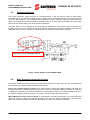
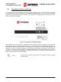
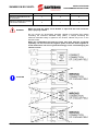
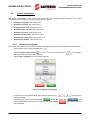
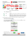
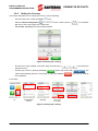
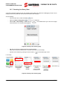
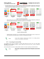
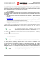
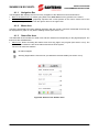
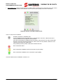
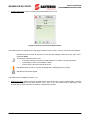
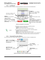
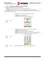
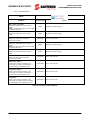
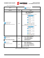
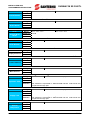
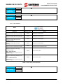
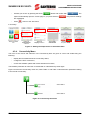
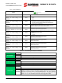
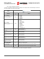
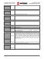
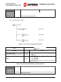
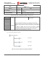
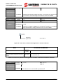
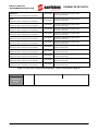
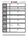
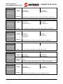
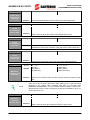
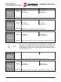
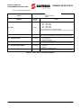
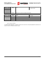
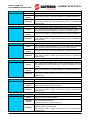
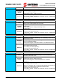
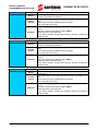
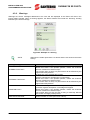
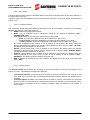
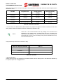
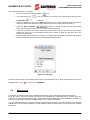
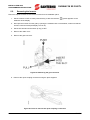
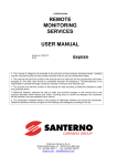
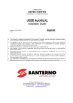
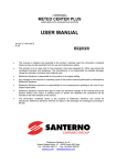
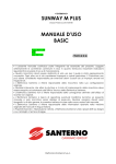
INSTALLATION AND
PROGRAMMING INSTRUCTIONS
SUNWAY M XS 3000TL
−
Set the IP address assignment mode. Select:
•
“DHCP” if you desire that the IP address is assigned by the router or access point (factory
setting). By selecting the “DHCP” mode, the additional connection parameters will be set up
directly by the router or access point. The IP address, however, may be changed by the router
or access point over time;
•
“STATIC” if you desire to manually enter the IP address to be assigned to the inverter. By
selecting the “STATIC” mode, the IP address will remain unchanged over time. The user is
required to know all the specifications of the connection network to avoid conflicts in assigning
static IP addresses of other devices. Also, the user is required to set any other connection
parameter after selecting the “STATIC” mode.
→
Select the
Connectivity
icon
→
Select the Wi-Fi
Status SSID
submenu
→
Select L307 – IP
Type
→
Select the
desired mode
and press Save
→
Confirm with OK
Figure 44: IP address assignment mode
−
Set the IP address (only if you chose the “STATIC” method for the IP address assignment). The set
up of this parameter requires knowing the network the inverter is to be connected to. The IP address
is to be composed of 12 digits, including any zeros.
→
Select the
Connectivity
icon
→
Select the Wi-Fi
Status SSID
submenu
→
Select L301 –IP
address (page 2)
→
Enter the value
and press Save
→
Confirm with OK
Figure 45: Setting the IP address
−
Set the subnet mask (only if you chose the “STATIC” method for the IP address assignment). Setting
this parameter requires knowing the network the inverter is to be connected to. A typical value for
domestic environments is 255.255.255.000.
→
Select the
Connectivity
icon
→
Select the Wi-Fi
Status SSID
submenu
→
Select L302 Subnet mask
(page 2)
→
Enter the desired
value and press
Save
Figure 46: Setting the subnet mask
48/124
→
Confirm with OK
INSTALLATION AND
PROGRAMMING INSTRUCTIONS
•
SUNWAY M XS 3000TL
Set the gateway (only if you chose the “STATIC” method for the IP address assignment). Setting this
parameter requires knowing the network the inverter is to be connected to. A typical value for domestic
environments is the IP address of the router or the access point.
→
Select the
Connectivity
icon
→
Select the Wi-Fi
Status SSID
submenu
→
Select L303 –
Gateway (page
2)
→
Enter the desired
value and press
Save
→
Confirm with OK
Figure 47: Setting the gateway
−
Set the DNS (only if you chose the “STATIC” method for the IP address assignment). Setting this
parameter requires knowing the network the inverter is to be connected to.
→
Select the
Connectivity
icon
→
Select the Wi-Fi
Status SSID
→
Select L311 –
DNS (page 2)
→
Enter the desired
value and press
Save
→
Confirm with OK
Figure 48: Setting the DNS
−
Activate the Wi-Fi connection (3.7.1). If the Wi-Fi status icon is green and the screen is similar to the
one in Figure 59, this means that the connection is completed successfully.
NOTE
3.7.2.
In the event of failures connecting the inverter to an existing network,
contact your local Network Administrator.
Accessing the Inverter Data
The SUNWAY M XS may be monitored in wireless mode directly by the user, who can check status
information, such as operating measures, alarms tripped and events fired, with no need to implement
demanding wiring solutions.
Data exchange with the inverter is made possible via a Wi-Fi connection operating as described above.
NOTE
Data access is protected by a password associated with the serial number
of the product. The password is given in a form contained in the box of the
product.
49/124
SUNWAY M XS 3000TL
INSTALLATION AND
PROGRAMMING INSTRUCTIONS
The consulting modes below are available only when the inverter is powered on. If the PV field voltage is too
weak (higher than the value set in P020 – FIELD REFERENCE), the inverter stops after the time set in P041
– POWER OFF TIMEOUT. Parameter P041 may be changed by the user to keep the inverter on for the
desired time even when the PV field reference is too weak, in order to exploit the functionality described
above. Setting parameter P041 to 0 fully inhibits the inverter shut down.
3.7.2.1. Web Browser
The Web Browser application is compatible with the most popular web browsers, such as Chrome, Firefox,
Internet Explorer (version 8 or greater) and Safari. Do the following to consult the information made available
by the inverter:
−
Open the web browser from the device connected to the same “ROUTER” or “AD HOC” network as
the inverter;
−
In the address bar of the browser, enter the IP address of the target inverter (e.g.
http://192.168.0.3);
−
When you are required for authentication, enter the serial number of the product as the username
and enter the password received when purchasing the product;
−
Navigate through the contents made available from the application. The values on the right of the
web page are updated every minute.
If multiple inverters are connected to the same wireless network, the web-like page will display the data
relating to all the connected inverters, both as discrete data and as aggregate data, after entering the
authentication parameters for all the inverters.
NOTE
The authentication parameters may be stored by the browser to avoid
entering them each time a connection is established. The user is
responsible for any implications in terms of information protection.
The web-like page displayed by the inverter features on-line Help functionality that can be activated by
pressing the
icon in the top-right corner.
3.7.2.2. iPhone application
NOTE
The iPhone application is available for iPhone 3 and more recent models.
The iPhone Application developed by Elettronica Santerno for the connection to the SUNWAY M XS
inverters may be downloaded from Apple iTunes.
The iPhone Application allows displaying the status info of the inverter as well as the main operating
measures, both in local mode and in remote mode—after the first connection in local mode has been
established. The inverter is to be enabled for accessing the Internet via the Wi-Fi connection and the
Sunwayportal.it service is to be activated (parameter L505).
NOTE
50/124
The iPhone Application generates data traffic. Costs may vary based on the
user’s tariff plan. Costs are charged to the user.
INSTALLATION AND
PROGRAMMING INSTRUCTIONS
SUNWAY M XS 3000TL
Do the following to consult the inverter data from your iPhone:
−
Launch the SUNWAY M XS application;
−
Figure 49: Icon of the SUNWAY M XS application on the iPhone
−
Complete the startup wizard;
−
When you are required for authentication, enter the serial number of the product as the username
and enter the password received when purchasing the product;
−
Navigate through the contents made available from the application.
3.7.3.
Sunwayportal.it
The SUNWAY M XS inverters, if connected to the Internet via Wi-Fi, may send the main info about the
inverter status and measures to the Sunwaportal.it service of Elettronica Santerno SpA. Information may be
accessed in remote mode as well.
Sending data to the Sunwayportal.it is a functionality that can be enabled from the Services submenu in the
Connectivity menu. Do the following to access the Sunwayportal.it service:
−
Activate the Sunwayportal.it functionality:
→
Select the
Connectivity icon
→
Select the
Services submenu
→
Select L505 –
SUNWAYPORTAL
.IT
→
Select ENABLE
and press Save
Confirm with OK
Figure 50: Activating the Sunwayportal.it service
Once the Sunwayportal.it functionality is activated, proceed with authentication entering the serial number of
the inverter as the username and the password given in the form contained in the box of the product.
51/124
INSTALLATION AND
PROGRAMMING INSTRUCTIONS
SUNWAY M XS 3000TL
3.7.4.
Technical Support
The SUNWAY M XS inverters, if connected to the Internet via Wi-Fi, may be remotely accessed by the
Customer Service of Elettronica Santerno SpA. Assistance is given via an encrypted communication channel
between the inverter and Elettronica Santerno SpA Customer Service, whose staff is allowed to access the
measures and programming parameters of the inverter. This functionality allows the Customer Service to
promptly operate on the inverter.
Before activating the Technical Support, contact the Customer Service of Elettronica Santerno SpA with the
serial number of the inverter. The Technical Support functionality may be activated from the Services
submenu in the Connectivity menu. Do the following:
−
Activate the Technical Support functionality:
→
Select the
Connectivity icon
→
Select the
Services menu
→
Select L502 –
Technical
Support
→
Select ENABLE
and press Save
Confirm with OK
Figure 51: Activating the Technical Support Service
−
Check if the Technical Support functionality is activated:
→
Select the Wi-Fi
Status icon
Wait until the
“Technical
support is active”
message appears
Figure 52: Checking the Technical Support Service
NOTE
52/124
The activation of the Technical Support is persistent. The Technical
Support functionality is to be deactivated when assistance is finished.
The date and time of the inverter must be correctly set up for the activation
of the Technical Support functionality.
INSTALLATION AND
PROGRAMMING INSTRUCTIONS
3.7.5.
SUNWAY M XS 3000TL
Connectivity Troubleshooting
o
The desired network is not listed among the available networks
Possible cause:
o The router cannot be detected by the inverter because it is too far
o The router has a hidden wireless network
o
No connection is established between the inverter and the selected router
Possible cause:
o The router is too far from the inverter and no stable connection may be established
o Wrong password entered (the password is case-sensitive)
o The router does not implement WPA cryptography for the network security
o The inverter is assigning a DHCP IP address and the router DHCP is disabled
o The inverter is assigning a STATIC IP address and the address being set up is in conflict
with the address of a different device connected to the same network
o
No connection to the Internet is established from the inverter
Possible cause:
o The router is not connected to the Internet
o The Gateway is set to a wrong value. The typical Gateway IP address displayed on the WiFi status window must be the same IP address of the router. Contact your network
administrator for complex networks
o The DNS is set to a wrong value. The factory setting (8.8.8.8) is to be left unchanged.
o
The Technical Support service is not correctly activated
Possible cause:
o The inverter fails connecting to the Internet. See the case in point
o Date and time are not set correctly
o
The inverter is connected to the selected network but the web page cannot be accessed
Possible cause:
o The device from which you are trying to consult the web page is not connected to the same
network as the inverter
53/124
INSTALLATION AND
PROGRAMMING INSTRUCTIONS
SUNWAY M XS 3000TL
3.8.
Datalogging
The SUNWAY M XS inverters may store the measures listed in Table 4.
The user may display the history measures over 4 time intervals:
−
the latest day, considered as the latest 24 hours, with a resolution of 1 data item/minute;
−
the latest week, considered as the latest 7 days, with a resolution of 1 data item/day;
−
the latest month, considered as the latest 30 days, with a resolution of 1 data item/day;
−
the latest year, considered as the latest 52 weeks, with a resolution of 1 data item/week.
The stored data may be displayed by selecting the measure inside the desired menu and by accessing the
relevant graph. Figure 53 is an example of how to display a measure graph.
→
Select the Info icon
→
Select the Grid
submenu
→
→
Select MPWR –
Power to Grid
Select the
icon
Select the
to change the time
interval
Figure 53: Displaying a measure graph
The user may also choose 3 measures from Table 4 to customize the Main Graph (4.3.3).
Type
Can be
graphically
represented
(Temperature) Boost
Measure
Yes
Grid Current
Field 1 Current
(Temperature) Heatsink
Power to Grid
Grid Voltage
Field 1 Voltage
Field 2 Voltage
Internal Temperature
Grid Frequency
Field 2 Current
Measure
Measure
Measure
Measure
Measure
Measure
Measure
Measure
Measure
Measure
Yes
Yes
Yes
Yes
Yes
Yes
Yes
Yes
Yes
Yes
ID
Function
Empty
M058
M006
M002
M059
MPWR
M004
M000
M021
M057
M005
M024
Table 4: Logged variables
54/124
icon
again to switch to a
different time
interval
INSTALLATION AND
PROGRAMMING INSTRUCTIONS
SUNWAY M XS 3000TL
4. GRAPHIC INTERFACE MODULE
The full-colour, graphic touchscreen display is located on the inverter front. The touchscreen display is the
HMI of the inverter. When the inverter is powered on, the appearance of the graphic interface module is as in
Figure 54.
Navigation bar
Menu area
Status bar
Stop
Start
Wake UP
Figure 54: Graphic interface module/Touchscreen display – Start menu
The START button for the inverter startup and the STOP button for the inverter stoppage, due to
maintenance reasons, are located in the bottom part of the graphic interface module.
Pressing the START button is required only for the inverter commissioning. Once commissioned, the inverter
will automatically start up every morning when the required operating conditions are achieved.
After pressing the STOP button, the inverter is kept stopped until the START button is pressed again,
regardless of the operating conditions.
NOTE
Press START after commissioning or maintaining the inverter to restore the
normal operation of the inverter. If this is not the case, the inverter will not
automatically restart even though the correct operating conditions are
restored.
In the absence of solar radiation, the inverter will automatically deactivate. When solar radiation is enough to
start the inverter, the SUNWAY M XS will automatically restart and will resume energy generation. The
inverter may be restarted at any time by pressing the WAKE UP button from the graphic interface module.
.
55/124
INSTALLATION AND
PROGRAMMING INSTRUCTIONS
SUNWAY M XS 3000TL
When the inverter is started, the touchscreen display shows the following screens in sequence:
→
Santerno Logo
→
Sunway M screen
→
Loading… screen
→
Start menu
Default screen
(Graph as a
factory setting)
Figure 55: Screens of the graphic interface module at power on
When no input has been received for 5 minutes, the touchscreen display automatically turns off to reduce
self-consumption to a minimum. Press anywhere on the display to turn it on again.
4.1.
Navigating in the Graphic Interface
The touchscreen display uses a menu and submenu tree to organize the information made available to the
user. Menus and submenus are divided into four main areas in the Menu Area in the main window (Figure
56). Touch an icon to navigate to its contents.
Navigation bar
Menu area
Status bar
Figure 56: Start menu
56/124
INSTALLATION AND
PROGRAMMING INSTRUCTIONS
SUNWAY M XS 3000TL
The graphic layout of the application is divided into 3 main areas:
Area
Description
The Navigation Bar is populated by different icons allowing the user
to know the navigation position inside the menus. Icons are
displayed based on the selected items in the menus.
The Menu Area displays the information about the product as well
as all the configuration parameters. These items are divided into
some areas identified on the main page by the 4 main buttons
below:
• Info menu (blue button)
• Graphic menu (yellow button)
• Connectivity menu (green button)
• Tools menu (grey button)
The Status Bar comprises the icons relating to the most important
information of the inverter for easy access from any part of the
menus. The 4 icons on the left allow navigating to the following:
• Alarm and event history data
• Wi-Fi status
• Inverter status
• Default view (4.3.5.2)
Additional buttons necessary to navigate inside the menus are
viewed if required by the organisation of the active menu.
Navigation bar
Menu area
Status bar
The areas above are populated by contents varying based on the current position in the menu tree.
Figure 57 shows an example of a screen. The main interactive items are described below.
Back to the
start menu
Menus and submenus icons
Navigation bar
Menu area
Items selectable from
the Menu Area
Status bar
Alarm icon
Variable icons
Wi-Fi status icon
Default view icon
Inverter status icon
Figure 57: Example of a screen
57/124
SUNWAY M XS 3000TL
4.1.1.
INSTALLATION AND
PROGRAMMING INSTRUCTIONS
Navigation Bar
The Navigation Bar displays the icons for easy navigation to the different menus and submenus:
• Back to the start menu icon: allows going back to the start menu from any position in the menus.
• Menu and submenu icons: graphically represent the current position in the menus. Select one of the
icons preceding the last icon from the right to return to the upper level.
4.1.2.
Menu Area
The Menu Area displays the items allowing interaction with the inverter. The items marked with an arrow may
be displayed as a graph or may lead to a dialog window (see section 4.3).
4.1.3.
Status Bar Area
The Status Bar Area includes four fixed icons and two variable icons depending on the page displayed. The
fixed icons are detailed below:
•
Alarms icon: allows accessing the Alarms menu from any page in the program (see section 4.3.6). The
Alarms menu contains the lists of the alarms and events of the system.
The icon can have two statuses:
No alarms tripped.
Alarm(s) tripped but the user has not yet viewed the relevant details (see section 4.3.6).
Figure 58: Screen of the Alarms menu
58/124
INSTALLATION AND
PROGRAMMING INSTRUCTIONS
•
SUNWAY M XS 3000TL
Wi-Fi Status icon: allows accessing the Wi-Fi Status menu, including Wi-Fi connectivity info, such as the
name of the network SSID, the IP address of the inverter and the quality of the Wi-Fi connection.
Figure 59: Screen of the Wi-Fi Status menu
The icon can have four statuses:
Hardware not fitted or hardware fault.
If your SUNWAY M XS is provided with an external Wi-Fi connector, make sure that it is
correctly inserted into the USB port of the inverter.
If the Wi-Fi functionality is integrated into the product, the grey Wi-Fi icon may indicate that
the Wi-Fi connection has been inactive for a while. If the icon is pressed, it will turn to red.
This does not indicate any malfunction.
If the problem persists, please contact the Customer Service.
Wi-Fi connection failed.
Wi-Fi connection established, but the connection is poor quality.
Wi-Fi connection established, the connection is good quality.
The Wi-Fi Status menu is detailed in section 4.3.9.
59/124
SUNWAY M XS 3000TL
•
INSTALLATION AND
PROGRAMMING INSTRUCTIONS
Inverter Status icon: allows accessing the inverter Status menu 4.3.9.
Figure 60: Screen of the inverter Status menu
The Status menu icon represents the operating conditions of the inverter. The icon can have three statuses:
Indicates that the inverter is powered, but the PV field voltage is lower than the value set in
parameter P020.
This inverter status normally occurs:
o in the early morning, when the PV field voltage is too weak for energy generation
o in the daytime, when solar radiation is weak
o in the evening, before the inverter shuts off
Indicates that the inverter is correctly operating and is feeding power to the grid.
Indicates that an alarm tripped.
The Status menu is detailed in section 4.3.7.
•
Default View icon: allows accessing the default view, that can be set up via the Customization > Display
submenu in the Tools menu (see sections 4.3.3.2 and 4.3.5). The default view is displayed by the
inverter after no input has been received for a reasonably long time.
60/124
INSTALLATION AND
PROGRAMMING INSTRUCTIONS
4.2.
SUNWAY M XS 3000TL
Display Windows and Data Enter Windows
The windows listed below make it possible to display the measures made available from the inverter and to
change the system settings:
1.
2.
3.
4.
Graph window. See section 4.2.1.
Alphanumeric keypad window. See section 4.2.2.
List window. See section 4.2.3.
Run Command window. See section 4.2.4.
4.2.1.
Graph Window
The graph window shows the pattern of the selected measure. This window may be accessed from the Menu
Area by selecting one of the measures marked with an arrow.
Figure 61: Example of a measure graph
The two right-most icons in the bottom-right corner of the Graph window may vary and allow doing the
following:
Accesses the key of the graph. Select the icon to display a list of the measures that are
graphically represented, their colour and instant value.
The graph may be customized from the Customization submenu in the Tools menu.
Selection of the time period. The icon allows changing the time period in the graph by selecting
one of the 4 time periods: the latest day, the latest week, the latest month or the latest year.
Press the icon repeatedly to switch from a time period to the other.
61/124
INSTALLATION AND
PROGRAMMING INSTRUCTIONS
SUNWAY M XS 3000TL
4.2.2.
Alphanumeric Keypad Window
The alphanumeric keypad window enables entering alphanumeric values in the selected field, as detailed
below:
VALUE FIELD
Displays the alphanumeric value
relating to the selected parameter.
MIN:
Indicates
the
minimum
allowable value.
DEF: Indicates the DEFAULT value
set for the inverter.
MAX: Indicates the maximum
allowable value.
KEYPAD
Alphanumeric keys enabling entering
the desired value.
STATUS
Message relating to data entering.
CANCEL BUTTON
Cancels the alphanumeric value
you have just entered and restores
the value which was previously
stored to memory.
The
programme
automatically
returns to the previous menu.
SAVE BUTTON
Stores to memory the alphanumeric
value you have just entered.
The programme returns to the previous
menu after pressing the OK button that
pops up after pressing Save.
WRITE BUTTON
Stores the alphanumeric value you have
just entered until the inverter is next
started (temporary storage).
The programme returns to the previous
menu after pressing the OK button that
pops up after pressing Write.
Figure 62: Example of an alphanumeric keypad window
By pressing an alphanumeric key from the keypad, the digit is displayed first, followed by the characters
included in the same key.
Some function keys are available:
•
Key “1”: if pressed twice, enters a space;
•
key “0”:
•
enters 0, -, + when entering digits
•
enters 0 and toggles between CAPS and lower case when entering text messages. The
activation of this functionality affects the latest character entered.
•
“Delete” key: deletes a character at a time from right to left.
The BASIC access level features two confirmation buttons:
− CANCEL cancels the data entered;
− SAVE stores the data entered to permanent memory.
NOTE
The ADVANCED access level features three confirmation buttons:
− CANCEL cancels the data entered;
− SAVE stores the data entered to permanent memory;
− WRITE stores the data entered until the inverter is next powered on
(temporary storage). The previous value is restored at next power on.
62/124
INSTALLATION AND
PROGRAMMING INSTRUCTIONS
4.2.3.
SUNWAY M XS 3000TL
List Window
The list window allows entering or changing a parameter chosen from a list, as detailed below:
ITEM LIST
Scrolling list of the available
items. The currently active
option is blue in colour.
Arrow keys scrolling up and
down the items in the list.
STATUS
Message for the execution of data
entering.
DEFAULT
Default value of the parameter.
CANCEL BUTTON
Cancels the latest modification
and keeps the current setting
active.
The
programme
automatically returns to the
previous menu.
SAVE BUTTON
Stores to memory the alphanumeric
value that you have just entered.
The programme returns to the
previous menu after pressing the OK
button that pops up after pressing
Save.
Figure 63: Example of a list window
The BASIC access level features two confirmation buttons:
− CANCEL cancels the data entered;
− SAVE stores the data entered to permanent memory.
The ADVANCED access level features three confirmation buttons:
NOTE
− CANCEL cancels the data entered;
− SAVE stores the data entered to permanent memory;
− WRITE stores the data entered until the inverter is next powered on
(temporary storage). The previous value is restored at next power on.
4.2.4.
Command Execution Window
This command execution window allows sending a command to the inverter, as detailed below:
NAME OF THE COMMAND
Area
of
the
window
displaying the name of the
active parameter.
RUN COMMAND
Allows
executing
command.
MESSAGING AREA
Area
of
the
window
displaying if the command
fails/succeeds.
the
BACK BUTTON
Returns to the previous
menu.
Figure 64: Example of a Run Command window
63/124
INSTALLATION AND
PROGRAMMING INSTRUCTIONS
SUNWAY M XS 3000TL
4.3.
Description of the Menus
The menus and submenus of the graphic interface module are divided into the four main areas represented
by the four icons in the start menu.
1
2
3
4
Figure 65: Icons of the Menu Area in the start menu
1. Info Menu
Measures and programming parameters of the inverter. See section 4.3.2 for details.
2. Graph Menu
Graphic display of the measures that can be customized by the user. See section 4.3.3 for details.
3. Connectivity Menu
Provides information about connectivity and relevant setting parameters. See section 4.3.4 for
details.
4. Tools Menu
Provides tools and configuration parameters of the inverter. See section 4.3.5 for details.
64/124
INSTALLATION AND
PROGRAMMING INSTRUCTIONS
4.3.1.
SUNWAY M XS 3000TL
Organisation of Measures and Parameters
The parameter configuration involves two access levels:
• BASIC (factory setting): displays the main measures and parameters;
• ADVANCED: displays the advanced measures and enables accessing all the parameters.
The access level may be changed by the user from Customization > Access Level > User Level in the
Tools menu (see section 4.3.5.2).
The BASIC access level features two confirmation buttons:
− CANCEL cancels the data entered;
− SAVE stores the data entered to permanent memory.
NOTE
The ADVANCED access level features three confirmation buttons:
− CANCEL cancels the data entered;
− SAVE stores the data entered to permanent memory;
− WRITE stores the data entered until the inverter is next powered on
(temporary storage). The previous value is restored at next power on.
NOTE
NOTE
Set the ADVANCED level to program the inverter parameters.
65/124
INSTALLATION AND
PROGRAMMING INSTRUCTIONS
SUNWAY M XS 3000TL
The information and configuration variables are grouped as follows:
o
Measures. These values may only be displayed and cannot be changed by the user. Each measure
is identified by letter M followed by 3 digits (e.g. M001). Measures are detailed as follows in the
sections below:
Mxxx
Name of the
measure
Value displayed on the touchscreen
display (may be a decimal figure) plus
unit of measure
Range
Internal representation
Active
If present, this field indicates if and when the measure is valid. When
this field is not present, the measure concerned is considered as
ALWAYS active.
Address
Level
Function
Modbus address from which the measure is read (integer).
Access level (BASIC / ADVANCED).
Description of the measure.
Table 5: Template of the measure descriptive tables
o
Parameters. These values may be changed by the user in order to configure the inverter operation.
Each parameter is identified by one of the following letters: P, I, C or R. Each letter is followed by 3
digits (e.g. P020). Parameters are detailed as follows in the sections below:
Pxxx
Range
Value displayed on the touchscreen
Internal representation of the
display (may be a decimal figure) plus
device (integer)
unit of measure
Default
Factory setting of the parameter Factory setting of the parameter (as
(as represented internally).
displayed) plus unit of measure.
Level
Name of the
parameter
Access level (BASIC / ADVANCED).
If present, this field indicates if and when the measure is valid. When
Active
this field is not present, the measure concerned is considered as
ALWAYS active.
Device Address/Modbus address the parameter is read from or written
Id/Address
to (integer).
Function
Description of the parameter.
Table 6: Template of the parameter descriptive tables
o
Display variables. These values relate to the display. Some of them may only be displayed, some
other may be changed by the user. Each variable is identified by letter L followed by 3 digits (e.g.
L001). Variables are detailed as follows in the sections below:
Lxxx
Range
Name of the
variable
Default
Function
Value displayed on the touchscreen display (may be a decimal figure)
plus unit of measure
Factory setting of the parameter (as displayed) plus unit of measure.
Description of the parameter.
Table 7: Template of the variable descriptive tables
66/124
INSTALLATION AND
PROGRAMMING INSTRUCTIONS
4.3.2.
SUNWAY M XS 3000TL
Info Menu
The icons of the menus and submenus in the Info area are blue in colour and allow monitoring the inverter
measures. Each measure is identified by letter M followed by 3 digits.
Figure 66 shows the Info menu tree, while Table 8, Table 9 and Table 10 describe each submenu belonging
to the Info menu.
See Table 8
See Table 9
See Table 10
Figure 66: Info menu tree
67/124
INSTALLATION AND
PROGRAMMING INSTRUCTIONS
SUNWAY M XS 3000TL
4.3.2.1. Field Submenu
Menu
Submenu
Access Level
Action
M000 – FIELD 1 VOLTAGE
Displays the instant value of the PV field 1
voltage
NOTE: This measure is valid only if the PV field
is coupled to the inverter
BASIC
Displays the measure graph.
BASIC
Displays the measure graph.
M002 – FIELD 1 CURRENT
Displays the instant value of the PV field 1
current
M001 – MPPT 1 REFERENCE
ADVANCED
Displays the instant value of the MPPT
reference for PV field 1
None. View-only item.
M011 – FIELD 2 VOLTAGE
Displays the instant value of the PV field 2
voltage
NOTE: This measure is valid only if the PV field
is coupled to the inverter
BASIC
Displays the measure graph.
BASIC
Displays the measure graph.
M012 – FIELD 2 CURRENT
Displays the instant value of the PV field 2
current
M024 – MPPT 2 REFERENCE
Displays the instant value of the MPPT
reference for PV field 2
ADVANCED
None. View-only item.
ADVANCED
None. View-only item.
ADVANCED
None. View-only item.
ADVANCED
None. View-only item.
M017 – POSITIVE POLE INSULATION
RESISTANCE, FIELD 1
Displays if the insulation resistance of the
positive pole of PV field 1 is exceeding the
value required by the standards in force
M018 – POSITIVE POLE INSULATION
RESISTANCE, FIELD 2
Displays if the insulation resistance of the
positive pole of PV field 2 is exceeding the
value required by the standards in force
M019 – NEGATIVE POLE INSULATION
RESISTANCE
Displays if the insulation resistance of the
positive pole of PV fields 1 and 2 is exceeding
the value required by the standards in force
Table 8: Info menu, Field submenu
68/124
INSTALLATION AND
PROGRAMMING INSTRUCTIONS
M000
Field 1 Voltage
Range
Id/Address
Level
Function
SUNWAY M XS 3000TL
0 ÷ 6200
0 ÷ 620.0 V
1/1653
BASIC
PV field 1 voltage that has been measured.
M001
Range
0 ÷ 6200
0 ÷ 620.0 V
Id/Address 1/1651
Level
ADVANCED
MPPT 1 Reference
When the inverter is running, this is the measure of the voltage reference
Function generated by the MPPT of PV field 1; when the inverter is not running,
this is the voltage value of the PV field 1 voltage.
M002
Field 1 Current
M017
Positive Pole
Insulation
Resistance, Field
1
M018
Positive Pole
Insulation
Resistance, Field
2
M019
Negative Pole
Insulation
Resistance
M021
Field 2 Voltage
Range
Id/Address
Level
Function
0 ÷ 1925
0 ÷ 19.25 A
1/1655
BASIC
PV field current that has been measured.
Range
0÷1
KO÷OK
Id/Address 1/1670
Level
ADVANCED
Indicates if the insulation resistance to earth of the positive pole of PV
Function
field 1 is exceeding 700kOhm.
Range
0÷1
KO÷OK
Id/Address 1/1672
Level
ADVANCED
Indicates if the insulation resistance to earth of the positive pole of PV
Function
field 2 is exceeding 700kOhm.
Range
0÷1
KO÷OK
Id/Address 1/1670
Level
ADVANCED
Indicates if the insulation resistance to earth of the positive pole of PV
Function
fields 1 and 2 is exceeding 700kOhm.
Range
Id/Address
Level
Function
0 ÷ 6200
0 ÷ 620.0 V
1/1654
BASIC
Field 2 voltage that has been measured.
M022
Range
0 ÷ 6200
0 ÷ 620.0 V
Id/Address 1/1656
Level
ADVANCED
MPPT 2 Reference
When the inverter is running, this is the measure of the voltage reference
Function generated by the MPPT of PV field 2; when the inverter is not running,
this is the voltage value of the PV field 2 voltage.
M024
Field 2 Current
Range
Id/Address
Level
Function
0 ÷1925
0 ÷ 19.25 A
1/674
BASIC
Field current that has been measured.
69/124
INSTALLATION AND
PROGRAMMING INSTRUCTIONS
SUNWAY M XS 3000TL
4.3.2.2. Inverter Submenu
Menu
Submenu
Access
Level
Action
Select the icon to display the following items:
−
M089 – INVERTER STATUS
−
M090 – ACTIVE ALARM
−
ALARM HISTORY
Displays the Alarm History. See section 4.3.6 for details.
BASIC
Displays the Event History and the Alarm
History
•
EVENT HISTORY
Displays the Event History. See section 4.3.6 for details.
BASIC
Select the icon to display the following items:
•
MLBL – SUNWAY M XS MODEL
•
PRSN – SERIAL NUMBER
•
L000 – DISPLAY SOFTWARE
•
INVERTER SOFTWARE
•
M040 – COUNTRY
BASIC
Select the icon to display the following items:
•
M098 – SUPPLY TIME
•
M099 – OPERATION TIME
•
M058 – BOOST TEMPERATURE
•
M059 – HEATSINK TEMPERATURE
Displays the measure graph.
•
M057 – INTERNAL TEMPERATURE
Displays the measure graph.
Displays the information on the product
specifications and programming modes
Displays diagnostic information
Table 9: Info menu, Inverter submenu
70/124
INSTALLATION AND
PROGRAMMING INSTRUCTIONS
M089
Inverter Status
M090
Active Alarm
MLBL
Sunway M XS
Model
PRSN
Serial Number
L000
Display Software
SWVer
Inverter Software
L004
Menu Version
M097
Operation Time
M098
Range
Id/Address
Level
Function
See Table 25
See Table 25
1/1662
BASIC
Describes the operating conditions of the inverter.
Range
Id/Address
Level
Function
See section 4.3.6
1/7711
BASIC
Active alarm.
See section 4.3.6
Range
Id/Address
Level
Function
2200, 3000, 3800
1/1706
BASIC
Indicates the size of the product.
2200, 3000, 3800
Range
Id/Address
Level
Function
0 ÷ 9999999
0 ÷ 9999999
1/517
BASIC
Indicates the serial number of the product.
Range
Level
Function
Range
Id/Address
Level
Function
Range
Level
Function
Range
Address
Level
Function
Internal
Temperature
N/A
BASIC
Indicates the software version installed on the touchscreen display.
0÷9999
0÷9999
1/475
BASIC
Indicates the software version installed on the inverter microcontrollers.
N/A
BASIC
Indicates the version of the menu structure.
Range
0 ÷ 232
0 ÷ 232 in units of 200 ms displayed as hh:min:sec
Id/Address 1/1684
Level
ADVANCED
Operation time of the inverter while delivering energy.
Function This measure is expressed in 32bits divided into two 16-bit words: the
low part and the high part.
Supply Time
M057
SUNWAY M XS 3000TL
Range
Address
Level
Function
0 ÷ 232
0 ÷ 232 n units of 200 ms displayed as hh:min:sec
1/1680
ADVANCED
Time when the inverter is power supplied.
This measure is expressed in 32bits divided into two 16-bit words: the
low part and the high part.
-100 ÷ +120
-100,00 ÷ +150 °C
1/1661
ADVANCED
Measure of the temperature internal to the inverter.
71/124
INSTALLATION AND
PROGRAMMING INSTRUCTIONS
SUNWAY M XS 3000TL
M058
Boost
Temperature
M059
Heatsink
temperature
Range
Address
Level
Function
-100 ÷ +120
-100.00 ÷ +150 °C
1/1660
ADVANCED
Measure of the heatsink temperature in the boost converter area.
Range
Address
Level
Function
-100 ÷ +120
-100.00 ÷ +120 °C
1/1669
ADVANCED
Measure of the heatsink temperature in the inverter area.
4.3.2.3. Grid Submenu
Menu
Submenu
Access Level
M004 – GRID VOLTAGE
Displays the instant value of the grid voltage
M006 – GRID CURRENT
Displays the instant value of the grid current
Action
BASIC
Displays the measure graph.
BASIC
Displays the measure graph.
BASIC
Displays the measure graph.
BASIC
Displays the measure graph.
BASIC
Displays the results and the data when the autotest of the
interface protections has been made.
BASIC
None. View-only item.
BASIC
None. View-only item.
MPWR – GRID POWER
Displays the instant value of the power
delivered to the grid
M005 – GRID FREQUENCY
Displays the instant value of the grid
frequency
M324 – AUTOTEST
Displays the result of the autotest procedure
M010 – TOTAL ENERGY
Displays the total value of the energy
delivered to the grid
M200 – TOTAL PAY-OFF
Displays the total pay-off resulting from the
produced energy
M011 – PARTIAL ENERGY
Displays the partial energy delivered to the
grid
M201 – PARTIAL PAY-OFF
Displays the total pay-off resulting from the
produced energy
Table 10: Info menu, Grid submenu
M004
Grid Voltage
72/124
Range
Id/Address
Level
Function
0 ÷ 4950
0 ÷ 495.0 V
1/1657
BASIC
Measured grid voltage.
INSTALLATION AND
PROGRAMMING INSTRUCTIONS
M005
Grid Frequency
Range
Id/Address
Level
Function
M006
MPWR
0÷32768
0÷327.7Hz
1/1658
BASIC
Measured grid frequency.
2200TL: 0 ÷ 1800
3000TL: 0 ÷ 2400
3800TL: 0 ÷ 3000
Range
Grid Current
SUNWAY M XS 3000TL
2200TL: 0 ÷ 18.0 A
3000TL: 0 ÷ 24.0 A
3800TL: 0 ÷ 30.0 A
Id/Address 1/1667
Level
BASIC
Function Current fed to the grid.
2200TL: 0 ÷ 4000
2200TL: 0 ÷ 4000 W
3000TL: 0 ÷ 4000
3000TL: 0 ÷ 4000 W
3800TL: 0 ÷ 4000
3800TL: 0 ÷ 4000 W
Id/Address 1/1686
Level
BASIC
Function Active power delivered to the grid.
Range
Power to Grid
M010
Total Energy
M011
Partial Energy
M200
Total Pay-off
M201
Range
Id/Address
Level
Function
xxxxxkWh
0 ÷ 232
1/1672
BASIC
Active energy delivered to the grid.
Range
Id/Address
Level
Function
xxxxxkWh
0 ÷ 232
1/654
BASIC
Partial count of the active energy delivered to the grid.
Range
xxxxCur
0 ÷ 232
Id/Address 1/1676
Level
BASIC
This measure represents the total pay-off resulting from the total count of
Function the energy delivered to the grid, where Cur represents the currency set in
L403. The pay-off is displayed by setting the feed-in tariff in P130.
Range
Address
Level
Partial Pay-off
Function
NOTE
xxxxCur
0 ÷ 232
1/1678
BASIC
This measure represents the partial pay-off resulting from the total count
of the energy delivered to the grid, where Cur represents the currency set
in L403. The pay-off is displayed by setting the feed-in tariff in P130.
The partial energy counter may be reset from the Settings → Commands →
Partial Energy Reset submenu.
73/124
INSTALLATION AND
PROGRAMMING INSTRUCTIONS
SUNWAY M XS 3000TL
4.3.3.
Graph Menu
The icon of the Graph menu is yellow in colour. The Graph menu displays a graph window (4.2.1) where up
to three custom measures may be displayed. Measures may be selected from the Customization > Display
> Graph submenu (see section 4.3.5.2) in the Tools menu. The MPWR (Power to Grid) measure is
displayed as a factory setting.
The Graph menu may be set up as the Default View from Customization > Display > L450 – Default View
(factory setting).
Figure 67: Graph menu
4.3.3.1. Customization of the Measures to be Graphically Displayed
The selection of the measures to be graphically displayed is made from the Customization > Display
submenu in the Tools menu. Do the following:
−
From the start menu, select the Tools (
−
−
Select the Customization (
) icon, then the Display (
) submenu;
Select GRAPH, then select the measure to be customized. The screen below appears:
) icon;
Figure 68: Selection page for the measure to be graphically displayed
−
74/124
Scroll the list of the available measures with the arrow keys (
desired measure;
) and activate the
INSTALLATION AND
PROGRAMMING INSTRUCTIONS
SUNWAY M XS 3000TL
−
Activate your choice by pressing the Save (
−
−
system automatically quits the current page. If you press Cancel (
), the previous settings
are maintained;
Repeat the operation for the other measures (if any) to be graphically represented;
Press
to return to the start menu.
) button and confirm with
. The
In summary:
→
Select the Tools
icon
→
Select the
Customization
submenu
→
Select the
Display submenu
→
Select the Graph
item
→
Select one of the
three
customizable
measures
Select the
variable to be
graphically
represented, ,
press SAVE and
confirm with OK
Figure 69: Steps to take for the customization of the measures to be graphically displayed
4.3.3.2. Setting the Graph Menu as the Default View
Setting the Graph menu as the default view is possible from the Customization > Display submenu in the
Tools menu. Do the following:
−
From the start menu, select the Tools (
−
−
Select the Customization (
) icon, then select the Display (
Select Default View; the screen below appears:
) icon;
) submenu.
Figure 70: Setting page of the Default View
−
Scroll the list of the available measures with the arrow keys (
desired measure;
) and activate the
75/124
INSTALLATION AND
PROGRAMMING INSTRUCTIONS
SUNWAY M XS 3000TL
−
Activate your choice by pressing the Save (
) button and confirm with
system automatically quits the current page. If you press Cancel (
are maintained;
−
Press
. The
), the previous settings
to return to the start menu.
In summary:
→
Select the Tools
icon
→
Select the
Customization
submenu
→
Select the
Display submenu
→
Select L450 –
Default View
Select GRAPH
and press SAVE
Confirm with OK
Figure 71: Setting the Graph menu as the Default View
4.3.4.
Connectivity Menu
The icons of the menus and submenu in the Connectivity area are green in colour and enable doing the
following:
−
display the information about the connectivity status;
−
configure the Wi-Fi connection;
−
access the software update and remote assistance functions;
The identifier parameter for each item is marked with L or R followed by three digits.
Figure 72 shows the Connectivity menu tree, while Table 11 and Table 12 describe each parameter relating
to the inverter connectivity.
See Table 11
See Table 12
Figure 72: Connectivity menu tree
76/124
INSTALLATION AND
PROGRAMMING INSTRUCTIONS
SUNWAY M XS 3000TL
4.3.4.1. Wi-Fi Submenu
Menu
Submenu
Access Level
L399 – WI-FI STATUS
Displays the
parameter
current
setting
of
the
BASIC
Activates a list window. Select:
− OFF
− ON
of
the
BASIC
Activates a list window. Select:
− ROUTER: connection via Router or Access Point
− AD HOC: direct connection between the inverter and the
device (PC or Smartphone).
of
the
BASIC
Activates a window containing a list of the available networks.
Select the target network for the Wi-Fi connection.
Wi-Fi
BASIC
Activates an alphanumeric keypad window.
Set the password of the target network for the Wi-Fi connection.
L305 – CONNECTION TYPE
Displays the
parameter
current
setting
L308 – SELECTED NETWORK
Displays the
parameter
current
setting
L306 – WI-FI PASSWORD
Sets the
connection
password
for
the
L307 – IP TYPE
Displays the
parameter
setting
of
the
BASIC
Activates a list window. Select:
− DHCP
− STATIC
setting
of
the
BASIC
Activates an alphanumeric keypad window.
Write the desired IP address.
setting
of
the
BASIC
Activates an alphanumeric keypad window.
Set the desired value.
current
setting
of
the
BASIC
Activates an alphanumeric keypad window.
Set the desired value.
current
setting
of
the
BASIC
Activates an alphanumeric keypad window.
Set the desired value.
current
L301 – IP ADDRESS
Displays the
parameter
current
L302 – SUBNET MASK
Displays the
parameter
current
L303 – GATEWAY
Displays the
parameter
L311 – DNS
Displays the
parameter
Action
Table 11: Connectivity menu, Wi-Fi submenu
L399
Wi-Fi Status
L307
Connection Type
L308
Range
Default
Level
Function
OFF, ON
OFF
BASIC
This variable allows setting the activation status of the Wi-Fi connection.
Range
Default
Level
Function
ROUTER, AD HOC
ROUTER
BASIC
This variable selects the type of connection to establish.
Range
Default
Level
Select Grid
Function
N/A
default
BASIC
If a Wi-Fi ROUTER connection (section 3.7.1.3) is established, this
variable contains the name of the target network for the Wi-Fi connection.
The user may choose among a list populated based on the Wi-Fi networks
detected by the inverter. If an AD HOC connection is established (see
section 3.7.1.2), this variable assumes the “Sunway_MXS” value.
77/124
SUNWAY M XS 3000TL
L306
Wi-Fi Password
Range
Default
Level
Function
L307
IP Address
Assign Mode
L301
Range
Default
Level
Function
Range
Default
Level
IP Address
Function
L302
Range
Default
Level
Subnet Mask
Function
L303
Range
Default
Level
Gateway
Function
L311
DNS
Range
Default
Level
Function
78/124
INSTALLATION AND
PROGRAMMING INSTRUCTIONS
Alphanumeric value ranging from 8 to 63 characters
Default
BASIC
This variable contains the password enabling accessing the target
wireless network for the Wi-Fi connection.
DHCP, STATIC
DHCP
BASIC
This variable selects the assign mode of the IP address of the inverter
when this is connected to an existing network.
DHCP = the address is assigned to the inverter by an external agent, such
as the reference access point.
STATIC = the user sets the IP address of the inverter.
000.000.000.000 ÷ 255.255.255.255
N/A
BASIC
This variable represents the IP address of the inverter when connected to
a communications network. This variable is read-only for the ROUTER
connection, with active DHCP and for the AD HOC connection. This
variable may be written by the user in ROUTER mode, with inactive
DHCP (STATIC IP address assigned). See variable L307.
000.000.000.000 ÷ 255.255.255.255
255.255.248.000
BASIC
This variable represents the subnet mask of the inverter when connected
to a communications network. This variable is read-only for the ROUTER
connection, with active DHCP and for the AD HOC connection. This
variable may be written by the user in ROUTER mode, with inactive
DHCP (STATIC IP address). See variable L307.
000.000.000.000 ÷ 255.255.255.255
000.000.000.000
BASIC
This variable represents the IP address of the network gateway. This
variable is read-only for the ROUTER connection, with active DHCP and
for the AD HOC connection. This variable may be written by the user in
ROUTER mode, with inactive DHCP (STATIC IP address).
Setting a wrong variable may compromise the right connection of the PC
or the Smartphone to the inverter, thus compromising the inverter access
to the Internet.
000.000.000.000 ÷ 255.255.255.255
8.8.8.8
BASIC
This variable represents the IP address of the DNS. Setting a wrong
variable compromises the inverter access to the Internet.
INSTALLATION AND
PROGRAMMING INSTRUCTIONS
SUNWAY M XS 3000TL
4.3.4.2. Services Submenu
Menu
Submenu
Access Level
BASIC
Activates a list window. Select:
− DISABLED
− ENABLED
BASIC
Activates a list window. Select:
− DISABLED
− ENABLED
BASIC
Activates a list window. Select:
− DISABLED
− ENABLED
BASIC
Activates a “Run command” window.
Press the Run Command button.
The messages relating to the execution of the command will be
displayed.
L505 – SUNWAYPORTAL.IT
Displays the current setting of the
parameter
L502 – TECHNICAL SUPPORT
Displays the current setting of the
parameter
L010 – DISPLAY UPDATE
Displays the current setting of the
parameter
L501 – INVERTER UPDATE
Enables updating the inverter firmware
Action
Table 12: Connectivity menu, Services submenu
L505
Sunwayportal.it
L502
Technical
Support
L010
Display Update
Range
Default
Level
Function
Range
Default
Level
Function
Range
Default
Level
Function
L501
Inverter Update
Range
Level
Function
DISABLED, ENABLED
ENABLED
BASIC
This variable enables the activation of the Sunwayportal.it service.
DISABLED, ENABLED
DISABLED
BASIC
This variable enables the activation of the Technical Support.
The Technical Support service enables remote access to the inverter
measures and programming parameters by the Customer Service of
Elettronica Santerno SpA.
The inverter is to be connected to a Wi-Fi network and is to be connected
to the Internet for the activation of the service.
DISABLED, ENABLED
DISABLED
BASIC
This variable enables the update procedure of the software implemented
in the touchscreen display.
N/A
BASIC
This variable enables the update procedure of the firmware implemented
in the inverter.
79/124
INSTALLATION AND
PROGRAMMING INSTRUCTIONS
SUNWAY M XS 3000TL
4.3.5.
Tools Menu
The icons of the menus and submenus belonging to this macroarea are grey in colour and enable displaying
the operating parameters that can be changed by the user. The identifier parameter for each item is marked
with letter P, C, I, L and R followed by three digits.
The SUNWAY M XS inverter is factory-set with a set of parameters fitting most applications. Therefore, the
Quick Configuration settings are normally sufficient for the correct operation of the inverter.
Figure 73 shows the Tools menu tree. The submenus in the Tools menu are detailed in the sections below.
See Table 13
See Table 14,
Table 15 and Table 16
See Table 17, Table 18, Table 19
and Table 20
See Table 21
Cannot be accessed by the user
Figure 73: Tools menu tree
80/124
INSTALLATION AND
PROGRAMMING INSTRUCTIONS
SUNWAY M XS 3000TL
4.3.5.1. Quick Configuration Submenu
The Quick Configuration submenu groups the settings to be configured when commissioning the inverter for
its correct operation. See section 3.6 for details.
Menu
Submenu
Access
Level
L402 – LANGUAGE
Displays the current language of
the touchscreen display
BASIC
P040 – COUNTRY
Displays the Country for the grid
interface configuration
BASIC
L404 – TIME ZONE
Displays the time zone set for
the inverter
Activates a list window.
Select the desired time zone.
BASIC
Activates a list window.
Select the desired date.
BASIC
Activates a list window.
Select the desired time.
BASIC
Activates a list window.
Select the desired currency.
BASIC
Activates a list window.
Select the desired value.
BASIC
Activates a run command window.
Press the Run Command button and wait for the success message.
BASIC
Activates a run command window.
Press the Run Command button and wait for the success message.
When the command is run, the touchscreen display will be shut off and restarted.
L401 – TIME
Displays the time set for the
inverter
L403 – CURRENCY
Displays the currency set for the
inverter
Activates a list window. You can select one of the following:
− ITALIANO
− ENGLISH
− ESPAÑOL
− FRANÇAIS
− DEUTSCH
Activates a list window. You can select one of the following:
− ITALIA
− ESPAÑA
− CONT. GREECE
− GREEK ISLANDS
− FRANCE
− BELGIQUE
− AUSTRALIA
− DEUTSCHLAND
− UK
− PORTUGAL
− EXT. NEUTRAL ENS
BASIC
L400 – DATE
Displays the date set for the
inverter
Action
P130 – INCENTIVE
Displays the remuneration
incentive for the produced
energy
L500 – HISTORY RESET
Resets the alarm history of the
touchscreen display
L011 – DISPLAY RESET
Resets the touchscreen display
Table 13: Tools menu, Quick Configuration submenu
81/124
SUNWAY M XS 3000TL
L011
Display Reset
L400
Date
Range
Default
Level
Function
Range
Default
Level
Function
L401
Time
Range
Default
Level
Function
L402
Language
L403
Currency
Range
Default
Level
Function
Range
Default
Level
Function
L404
Range
Default
Level
Time Zone
Function
L500
History Reset
Range
Default
Level
Function
82/124
INSTALLATION AND
PROGRAMMING INSTRUCTIONS
N/A
N/A
BASIC
This is a command to reset the touchscreen display.
01/01/1970 ÷ 19/01/2038
01/01/1970
BASIC
Sets the date for the inverter. If the inverter is connected to the Internet,
the date will be automatically updated.
00:00 ÷ 23:59
00:00
BASIC
Sets the time for the inverter. If the inverter is connected to the Internet,
the date will be automatically updated based on the time zone set in L404.
ITALIANO, ENGLISH, ESPAÑOL, FRANÇAIS, DEUTSCH
ENGLISH
BASIC
Sets the language for the graphic interface programme.
AUD, BRL, CAD, CHF, DKK, EUR, GBP, INR, JPY, NOK, NZD, RMB,
RUB, SEK, USD
EUR
BASIC
Sets the currency. The currency is used for M200 – Total Pay-off and
M201 – Partial Pay-off.
Amsterdam, Andorra, Athens, Belgrade, Berlin, Bratislava, Brussels,
Bucharest, Budapest, Chisinau, Copenhagen, Dublin, Gibraltar, Guernsey,
Helsinki, Isle of man, Istanbul, Jersey, Kaliningrad, Kiev, Lisbon, Ljubjana,
London, Luxembourg, Madrid, Malta, Mariehamn, Misnk, Monaco,
Moscow, Oslo, Paris, Podgorica, Prague, Riga, Rome, Samara, San
Marino, Sarajevo, Simferopol, Skopje, Sofia, Stockholm, Tallinn, Tirane,
Uzhgorod, Vaduz, Vatican, Vienna, Vilnius, Volgograd, Warsaw, Zagreb ,
Zaporozhye, Zurich
Rome
BASIC
Sets the time zone for the inverter. This setting takes effect if the inverter
is connected to the Internet. In that case, the inverter will automatically
update its time based on the set time zone.
N/A
N/A
BASIC
This command resets the history data from the display.
This command permanently deletes the history data saved on the display.
INSTALLATION AND
PROGRAMMING INSTRUCTIONS
P130
Range
Default
Level
Address
Incentive
Function
SUNWAY M XS 3000TL
0 ÷ 10000
0.0 ÷ 10.000 Unit / kWh
0
0 Unit / kWh
BASIC
676
This parameter sets the remuneration per kWh produced. The currency
may be set via parameter L403.
4.3.5.2. Customization Submenu
See Table 14
See Table 15
See Table 16
Figure 74: Tools menu, Customization submenu
Menu
Access
Level
Submenu
L450 – DEFAULT VIEW
Displays the current setting for the Default View
GRAPH
BASIC
BASIC
Action
Activates a list window. Select one of the following:
− GRAPH
− HOMEPAGE
Displays the following items:
− L451 – MEASURE 1
− L452 – MEASURE 2
− L453 – MEASURE 3
Each item activates a list window. You can select one of the Measure
values listed in Table 4.
Table 14: Tools menu, Customization > Display submenu
L450
Range
Default
Level
Default
Function
GRAPH, HOMEPAGE
GRAPH
BASIC
Enables the customization of the Default View of the product. The default
screen is displayed by the inverter when no input has been received for a
reasonably long time.
83/124
INSTALLATION AND
PROGRAMMING INSTRUCTIONS
SUNWAY M XS 3000TL
L451
Measure 1
L452
Measure 2
L453
Measure 3
Range
Default
Level
Function
See Table 4
MPWR
BASIC
Enables the customization of measure 1 in the main Graph.
Range
Default
Level
Function
See Table 4
EMPTY
BASIC
Enables the customization of measure 2 in the main Graph.
Range
Default
Level
Function
See Table 4
EMPTY
BASIC
Enables the customization of measure 3 in the main Graph.
Menu
Access
Level
Submenu
BASIC
Activates a list window. Select one of the following:
− BLACK
− WHITE
− RED
− BLUE
BASIC
Activates an alphanumeric keypad window.
Set the inverter identifier on the web page.
L503 – INVERTER COLOUR
Displays the current setting for the inverter
colour.
This setting affects the colour of the icon
displayed on the browser web page (3.7.2.1)
Action
L504 – LABEL
Displays the current setting for the inverter label.
This setting affects the label of the icon
displayed on the browser web page (3.7.2.1)
Table 15: Tools menu, Customization > Web Page submenu
L503
Inverter Colour
Range
Default
Level
Function
L504
Range
Default
Level
Label
Function
84/124
BLACK, WHITE, RED, BLUE
N/A
BASIC
Selects the colour of the product icon displayed on the browser web page
(3.7.2.1). This parameter is factory set to the colour of the product.
N/A
S/N
BASIC
Enables the customization of the product name displayed on the browser
web page (3.7.2.1).
This parameter is factory set to the serial number of the product.
INSTALLATION AND
PROGRAMMING INSTRUCTIONS
SUNWAY M XS 3000TL
Menu
Access
Level
Submenu
P001 – USER LEVEL
BASIC
Displays the current level for the user level
SW0 – SERVICE PASSWORD
ADVANCED
Action
Activates a list window. Select one of the following:
− BASIC
− ADVANCED
Activates an alphanumeric keypad window.
Enter the Service password. This functionality is reserved to the
Customer Service of Elettronica Santerno SpA.
Table 16: Tools menu, Customization submenu > Access Level
P001
Range
Default
Level
Address
User Level
Function
0÷1
0: BASIC
1: ADVANCED
0: BASIC
0
BASIC
1/291
The programming parameters of the inverter are divided into groups based
on user access levels, depending on the complexity of their function.
Therefore, based on the user level programmed in the touchscreen
display, the user is allowed to view only some menus or certain parts of
them.
By setting the BASIC user level, once the inverter is properly
parameterized, navigation is easier, since the user is shown a shorter set
of parameters including only the most frequently used parameters.
The preset user level is stated in the “Level” field.
4.3.5.3. Advanced Configuration Submenu
See Table 17
See Table 18
See Table 19
Figure 75: Tools menu, Advanced Configuration Submenu
85/124
INSTALLATION AND
PROGRAMMING INSTRUCTIONS
SUNWAY M XS 3000TL
Menu
Access
Level
Submenu
P026 – MPPT 1
ADVANCED
P020 – FIELD 1 REFERENCE
ADVANCED
P021 – STARTUP DELAY
ADVANCED
P300 – MPPT2
ADVANCED
P220 – FIELD 2 REFERENCE
ADVANCED
Action
Activates a list window. Select one of the following:
− INACTIVE
− ACTIVE
Activates an alphanumeric keypad window.
Enter the desired value.
Activates an alphanumeric keypad window.
Enter the desired value.
Activates a list window. Select one of the following:
− INACTIVE
− ACTIVE
Activates an alphanumeric keypad window.
Enter the desired value.
Table 17: Tools menu, Advanced Configuration > Field submenu
P020
Field 1 Reference
Range
Default
Level
Id/Address
Function
P021
Startup Delay
Range
Default
Level
Id/Address
Function
P026
Range
MPPT 1
Default
Level
Id/Address
Function
86/124
1100÷4000
110.V÷400V
2800
280V
ADVANCED
1/254
If the MPPT algorithm is disabled (P026=Inactive), P020 represents the
working voltage reference of PV field 1: the inverter will try to make the
PV field voltage match with the value set in P020.
0÷32767
0÷327.67s
300
300.0 s
ADVANCED
1/294
Minimum time when the open-circuit voltage of the PV field must be
longer than the time set in P020 to enable the inverter startup.
0÷1
0: Inactive
1: Active
1: Active
1
ADVANCED
1/1374
MPPT Enable: if P026 = Active, the MPPT (Maximum Power Point
Tracking) is enabled. If P026 is set to Inactive, the MPPT is in manual
mode and the field voltage reference is the one set in P020.
INSTALLATION AND
PROGRAMMING INSTRUCTIONS
P220
Field 2 Reference
Range
Default
Level
Id/Address
Function
P226
Range
MPPT 2
Default
Level
Id/Address
Function
SUNWAY M XS 3000TL
1100÷4000
110.V÷400V
2800
280V
ADVANCED
1/255
If the MPPT algorithm is disabled for PV Field 2 (P226=Inactive), P220
represents the working voltage reference of PV Field 2: the inverter will
try to make the PV field voltage match with the value set in P220.
0: Inactive
1: Active
1: Active
0÷1
1
ADVANCED
1/1375
MPPT Enable: if P030 = Active, the MPPT (Maximum Power Point
Tracking) is enabled. If P030 is set to Inactive, the MPPT is in manual
mode and the field 2 voltage reference is the one set in P020.
Advanced
parameters
See Table 18
Figure 76: Tools menu, Advanced Configuration > Inverter submenu
Menu
ADVANCED PARAMETERS
Access
Level
Submenu
P041 – POWER OFF DELAY
Displays the value currently set for the power
off delay
ADVANCED
Action
Activates an alphanumeric keypad window.
Enter the desired value.
Table 18: Tools menu, Advanced Configuration > Inverter > Advanced Parameters submenu
P041
Power Off Delay
Range
Default
Level
Address
Function
0 ÷ 32768
0 ÷ 546 min
900
15 min
ADVANCED
1/310
Time when the inverter is waiting for a field voltage value exceeding 150V;
when that time is over, the inverter is powered off.
87/124
INSTALLATION AND
PROGRAMMING INSTRUCTIONS
SUNWAY M XS 3000TL
Grid interface
See Table 19
Energy
See Table 20
Figure 77: Tools menu, Advanced Settings > Grid submenu
Menu
Submenu
C000 – RATED GRID VOLTAGE
Displays the value currently set for the parameter
C001 – RATED GRID FREQUENCY
Displays the value currently set for the parameter
P080 – INSTANT OVERVOLTAGE THRESHOLD
Displays the value currently set for the parameter
P081 – INSTANT OVERVOLTAGE RELEASE
RATIO
GRID INTERFACE
Access
Level
ADVANCED
Activates an alphanumeric keypad window.
Enter the desired value.
ADVANCED
Activates an alphanumeric keypad window.
Enter the desired value.
ADVANCED
Activates an alphanumeric keypad window.
Enter the desired value.
ADVANCED
Activates an alphanumeric keypad window.
Enter the desired value.
ADVANCED
Activates an alphanumeric keypad window.
Enter the desired value.
ADVANCED
Activates an alphanumeric keypad window.
Enter the desired value.
ADVANCED
Activates an alphanumeric keypad window.
Enter the desired value.
ADVANCED
Activates an alphanumeric keypad window.
Enter the desired value.
ADVANCED
Activates an alphanumeric keypad window.
Enter the desired value.
ADVANCED
Activates an alphanumeric keypad window.
Enter the desired value.
ADVANCED
Activates an alphanumeric keypad window.
Enter the desired value.
ADVANCED
Activates an alphanumeric keypad window.
Enter the desired value.
ADVANCED
Activates an alphanumeric keypad window.
Enter the desired value.
ADVANCED
Activates an alphanumeric keypad window.
Enter the desired value.
Displays the value currently set for the parameter
P082 – INSTANT OVERVOLTAGE TRIP TIME
Displays the value currently set for the parameter
P083 – INSTANT OVERVOLTAGE RESET TIME
Displays the value currently set for the parameter
P084 – MAXIMUM VOLTAGE TRIP THRESHOLD
Displays the value currently set for the parameter
P085 – MAXIMUM VOLTAGE RELEASE RATIO
Displays the value currently set for the parameter
P086 – MAXIMUM VOLTAGE TRIP TIME
Displays the value currently set for the parameter
P087 – MAXIMUM VOLTAGE RESET TIME
Displays the value currently set for the parameter
P088 – MINIMUM VOLTAGE TRIP THRESHOLD
Displays the value currently set for the parameter
P089 – MINIMUM VOLTAGE RELEASE RATIO
Displays the value currently set for the parameter
P090 – MINIMUM VOLTAGE TRIP TIME
Displays the value currently set for the parameter
P091 – MINIMUM VOLTAGE RESET TIME
Displays the value currently set for the parameter
88/124
Action
INSTALLATION AND
PROGRAMMING INSTRUCTIONS
P092
–
INSTANT
THRESHOLD
GRID
SUNWAY M XS 3000TL
UNDERVOLTAGE
ADVANCED
Activates an alphanumeric keypad window.
Enter the desired value.
ADVANCED
Activates an alphanumeric keypad window.
Enter the desired value.
ADVANCED
Activates an alphanumeric keypad window.
Enter the desired value.
ADVANCED
Activates an alphanumeric keypad window.
Enter the desired value.
ADVANCED
Activates an alphanumeric keypad window.
Enter the desired value.
ADVANCED
Activates an alphanumeric keypad window.
Enter the desired value.
ADVANCED
Activates an alphanumeric keypad window.
Enter the desired value.
ADVANCED
Activates an alphanumeric keypad window.
Enter the desired value.
ADVANCED
Activates an alphanumeric keypad window.
Enter the desired value.
ADVANCED
Activates an alphanumeric keypad window.
Enter the desired value.
ADVANCED
Activates an alphanumeric keypad window.
Enter the desired value.
ADVANCED
Activates an alphanumeric keypad window.
Enter the desired value.
Displays the value currently set for the parameter
P093 –
RATIO
INSTANT
UNDERVOLTAGE
RELEASE
Displays the value currently set for the parameter
P094 – INSTANT UNDERVOLTAGE TRIP TIME
Displays the value currently set for the parameter
P095 – INSTANT UNDERVOLTAGE RESET TIME
Displays the value currently set for the parameter
P096 – MAXIMUM FREQUENCY TRIP THRESHOLD
Displays the value currently set for the parameter
P097 – MAXIMUM FREQUENCY RELEASE RATIO
Displays the value currently set for the parameter
P098 – MAXIMUM FREQUENCY TRIP TIME
Displays the value currently set for the parameter
P099 – MAXIMUM FREQUENCY RESET TIME
Displays the value currently set for the parameter
P100 – MINIMUM FREQUENCY TRIP THRESHOLD
Displays the value currently set for the parameter
P101 – MINIMUM FREQUENCY RELEASE RATIO
Displays the value currently set for the parameter
P102 – MINIMUM FREQUENCY TRIP TIME
Displays the value currently set for the parameter
P103 – MINIMUM FREQUENCY RESET TIME
Displays the value currently set for the parameter
Table 19: Tools menu, Advanced Configuration > Grid > Grid Interface submenu
C000
Rated Grid
Voltage
Range
Default
Level
Id/Address
Function
1000 ÷ 6900
100.0 ÷ 690.0 V
230
230.0 V
ADVANCED
1 and 2/1307
This parameter sets the rated value of the grid voltage.
89/124
SUNWAY M XS 3000TL
C001
Rated Grid
Frequency
P080
Instant
Overvoltage
Threshold
P081
Instant
Overvoltage
Release Ratio
P082
Instant
Overvoltage Trip
Time
P083
Instant
Overvoltage
Reset Time
P084
Maximum
Voltage Trip
Threshold
P085
Maximum
Voltage Release
Ratio
90/124
INSTALLATION AND
PROGRAMMING INSTRUCTIONS
Range
Default
Level
Id/Address
Function
470 ÷ 630
47.0 ÷ 63.0 Hz
50.0
50.0Hz
ADVANCED
1 e 2/1308
This parameter sets the rated value of the grid frequency.
Range
Default
Level
Id/Address
120 ÷ 180
[120 ÷ 180] % of Vn
140
140
ADVANCED
1/1311
This parameter, expressed as a percentage of the rated grid voltage,
sets the trip threshold of the grid overvoltage fault.
Function
Range
Default
Level
Id/Address
Function
Range
Default
Level
Id/Address
Function
Range
Default
Level
Id/Address
Function
0 ÷ 1000
0.00÷ 1
950
0.95
ADVANCED
1/1312
This parameter sets ratio between the trip threshold of the overvoltage
fault and the value at which the overvoltage fault is reset.
1 ÷ 10000
0.001 ÷ 10.000 s
3
0.003s
ADVANCED
1/1313
This is the time during which the instantaneous overvoltage trip condition
must be maintained to prompt the activation of the grid overvoltage fault.
1 ÷ 10000
0.001 ÷ 10.000 s
20
0.02s
ADVANCED
1/1314
This is the time during which the instantaneous overvoltage reset
condition must be maintained to prompt the grid overvoltage fault reset.
Range
105 ÷ 130
[105 ÷ 130] % of Vn
120 (Italy),
120 (Italy),
Default
110 (Spain),
110 (Spain),
115 (Germany)
115 (Germany)
Level
ADVANCED
Id/Address 1/1315
This parameter is expressed as a percentage of the rated grid voltage; it
Function
sets the trip threshold for the grid maximum voltage fault.
Range
Default
Level
Id/Address
Function
0 ÷ 1000
0 ÷ 1.000
950
0.95
ADVANCED
1/1316
Sets the ratio between the trip voltage value for the maximum voltage
fault and the value at which it is reset.
INSTALLATION AND
PROGRAMMING INSTRUCTIONS
P086
Range
P087
Range
SUNWAY M XS 3000TL
1 ÷ 10000
0.001÷ 10.000s
100 (Italy),
0.1s (Italy),
Default
150 (Spain),
0.15s (Spain),
200 (Germany)
0.2s (Germany)
Maximum
Level
ADVANCED
Voltage Trip Time
Id/Address 1/1317
This is the time during which the maximum voltage trip condition must be
Function
maintained to prompt the activation of the grid maximum voltage fault.
Maximum
Voltage Reset
Time
P088
1 ÷ 10000
1 ÷ 10.000 s
100 (Italy),
0.1s (Italy),
Default
200 (Spain),
0.2s (Spain),
10000 (Germany)
10.0s (Germany)
Level
ADVANCED
Id/Address 1/1318
This is the time during which the maximum voltage reset condition must
Function
be maintained to prompt the reset of the grid maximum voltage fault.
Range
10 ÷ 95
[10 ÷ 95] % of Vn
80 (Italy),
80 (Italy),
Default
85 (Spain),
85 (Spain),
80 (Germany)
80 (Germany)
Minimum Voltage
Level
ADVANCED
Trip Threshold
Id/Address 1/1319
This parameter, expressed as a percentage of the rated grid voltage,
Function
sets the activation threshold of the grid minimum voltage fault.
P089
Range
Default
Level
Minimum Voltage
Id/Address
Release Ratio
Function
P090
Range
P091
Range
1000 ÷ 1499
1.000 ÷ 1.499
1050
1.050
ADVANCED
1/1320
Sets the ratio between the trip threshold of the minimum voltage fault and
the value at which the minimum voltage fault is reset.
1 ÷ 10000
0.001 ÷ 10.000s
200 (Italy),
0.2s (Italy),
Default
150 (Spain),
0.15s (Spain),
200 (Germany)
0.2s (Germany)
Minimum Voltage
Level
ADVANCED
Trip Time
Id/Address 1/1321
This is the time during which the minimum voltage trip condition must be
Function
maintained to prompt the activation of the minimum voltage fault.
1 ÷ 10000
0.001 ÷ 10.000s
100 (Italy),
0.1s (Italy),
Default
100 (Spain),
0.1s (Spain),
10000 (Germany)
10s (Germany)
Minimum Voltage
Level
ADVANCED
Reset Time
Id/Address 1/1322
This is the time during which the minimum voltage trip condition must be
Function
maintained to prompt the grid minimum voltage fault reset.
91/124
SUNWAY M XS 3000TL
P092
Instant Grid
Undervoltage
Threshold
P093
Instant
Undervoltage
Release Ratio
Range
Default
Level
Id/Address
Function
Range
Default
Level
Id/Address
Function
P094
Instant
Undervoltage
Trip Time
P095
Instant
Undervoltage
Reset Time
Range
Default
Level
Function
Range
Default
Level
Id/Address
Function
P096
30 ÷ 95
[35 ÷ 95] % of Vn
60
60
ADVANCED
1/1323
This parameter, expressed as a percentage of the grid rated voltage,
sets the activation threshold of the instant grid undervoltage fault.
1000 ÷ 1499
1.0 ÷ 1.499
1050
1.050
ADVANCED
1/1324
Sets the ratio between the trip threshold of the instant undervoltage fault
and the value at which the instant undervoltage fault is reset.
1 ÷ 10000
0.001 ÷ 10.000s
3ms
0.003s
ADVANCED
1/1325
Time during which the trip condition of the instant overvoltage must be
maintained to prompt the activation of the grid instant undervoltage fault.
1 ÷ 10000
0.001 ÷ 10.000s
10ms
0.010s
ADVANCED
1/1326
Time during which the trip condition of the instant overvoltage must be
maintained to prompt the reset of the grid instant undervoltage fault.
Range
Maximum
Frequency Trip
Threshold
10 ÷ 300
[0.1 ÷ 3.00] Hz
30 (Italy),
0.30Hz (Italy),
Default
100 (Spain),
1.00Hz (Spain),
20 (Germany)
0.20Hz (Germany)
Level
ADVANCED
Id/Address 1/1327
This parameter sets the maximum value of the frequency offset in
Function respect to the nominal value at which the grid maximum frequency fault
trips.
NOTE
P097
Maximum
Frequency
Release Ratio
Value set on the inverters delivered in Italy starting from 1 April 2012 and
identified by the relative label, compliant with CEI 0-21 according with
deliberation 84/2012/R/EEL. For the inverters delivered before 1 April 2012,
this parameter is set to 0.3Hz according to the previous standards in force, so
it has to be set to 1Hz.
Range
Default
Level
Id/Address
Function
92/124
INSTALLATION AND
PROGRAMMING INSTRUCTIONS
900 ÷ 1000
0.900 ÷ 1.000
998
0.998
ADVANCED
1/1328
Sets the ratio between the trip frequency of the maximum frequency fault
and the value at which the maximum frequency fault is reset.
INSTALLATION AND
PROGRAMMING INSTRUCTIONS
P098
SUNWAY M XS 3000TL
Range
Maximum
Frequency Trip
Time
P099
1 ÷ 10000
0.001 ÷ 10.000 s
50 (Italy),
0.05s (Italy),
Default
50 (Spain),
0.05s (Spain),
200 (Germany)
0.20s (Germany)
Level
ADVANCED
Id/Address 1/1329
Time during which the trip condition of the maximum frequency must be
Function
maintained to prompt the activation of the grid maximum frequency fault.
Range
Maximum
Frequency Reset
Time
P100
1 ÷ 10000
0.001 ÷ 10.000 s
10 (Italy),
0.01s (Italy),
Default
100 (Spain),
0.1s (Spain),
10000 (Germany)
10s (Germany)
Level
ADVANCED
Id/Address 1/1330
Time during which the reset condition of the maximum frequency must be
Function
maintained to reset the grid maximum frequency fault.
Range
Minimum
Frequency Trip
Threshold
10÷300
[-3.0 ÷ -0.1] Hz
30 (Italy)
-0.30Hz (Italy),
Default
200 (Spain)
-2.0Hz (Spain),
250 (Germany)
-2.5Hz (Germany)
Level
ADVANCED
Id/Address 1/1331
This parameter defines the maximum value of the frequency offset in
Function respect to the nominal value at which the grid minimum frequency fault
trips.
Value set on the inverters delivered in Italy starting from 01/04/2012 and
identified by the relative label, compliant with CEI 0-21 according with
deliberation 84/2012/R/EEL. For the inverters delivered before 01/04/2012,
this parameter is set to -0.3Hz according to the previous standards in force,
so it has to be set to -1Hz.
NOTE
P101
Minimum
Frequency
Release Ratio
P102
Minimum
Frequency Trip
Time
Range
Default
Level
Id/Address
Function
1000 ÷ 1500
1.000 ÷ 1.500
1002
1.002
ADVANCED
1/1332
Sets the ratio between the trip frequency of the minimum frequency fault
and the value at which the minimum frequency fault is reset.
Range
0 ÷ 10000
0.001 ÷ 10.000 s
50 (Italy),
0.050s (Italy),
Default
3000 (Spain),
3.000s (Spain),
250 (Germany)
0.200s (Germany)
Level
ADVANCED
Id/Address 1/1333
Time during which the trip condition of the minimum frequency must be
Function
maintained to prompt the activation of the grid minimum frequency fault.
93/124
INSTALLATION AND
PROGRAMMING INSTRUCTIONS
SUNWAY M XS 3000TL
P103
Range
Minimum
Frequency Reset
Time
40 ÷ 10000
0.04 ÷ 10.0 s
100 (Italy),
0.10s (Italy),
Default
100 (Spain),
0.10s (Spain),
10000 (Germany)
10.0s (Germany)
Level
ADVANCED
Id/Address 1/1334
Time during which the reset condition of the minimum frequency must be
Function
maintained to reset the minimum frequency fault.
Menu
ENERGY
Submenu
Access Level
P135L – FISCAL METER L PRESET
Displays the value currently set for the
parameter
ADVANCED
Activates an alphanumeric keypad window.
Enter the desired value.
ADVANCED
Activates an alphanumeric keypad window.
Enter the desired value.
P135H – FISCAL METER H PRESET
Displays the value currently set for the
parameter
Action
Table 20: Tools menu, Advanced Configuration > Grid > Energy submenu
P135L
Fiscal Meter L
Preset
Range
Default
Level
Id/Address
Function
P135H
Fiscal Meter H
Preset
Range
Default
Level
Id/Address
Function
94/124
0 ÷ 9999
0 ÷ 9999 Wh
0
0
ADVANCED Inactive function, do not use
2/1364
Start value for the computation of the energy produced by the inverter.
This parameter must match with P135H to obtain the desired value
based on P135H*10000 + P135L formula.
0 ÷ 10000
0 ÷ 10000 * 10 kWh
0
0
ADVANCED Inactive function, do not use
2/1365
Start value for the computation of the energy produced by the inverter.
This parameter must match with P135L to obtain the desired value based
on P135H*10000 + P135L formula.
INSTALLATION AND
PROGRAMMING INSTRUCTIONS
SUNWAY M XS 3000TL
4.3.5.4. Commands Submenu
Menu
Submenu
Access
Level
AUTOTEST
BASIC
L500 – HISTORY RESET
BASIC
RST – INVERTER RESET
ADVANCED
L011 – DISPLAY RESET
BASIC
I002 – PARTIAL ENERGY RESET
I008 – WARNING RESET
ADVANCED
BASIC
Action
Displays the following:
− I030 – TEST VMIN
− I031 – TEST VMAX
− I032 – TEST FMIN
− I033 – TEST FMAX
Each item activates a run command window.
For any details on the grid interface Autotest commands, see section
5.3.
Activates a run command window.
Press the Run Command button and wait for the success message.
Activates a list window. Select:
•
NO COMMAND
•
INVERTER RESET
Activates a run command window.
Press the Run Command button and wait for the success message.
Activates a list window. Select:
•
INACTIVE
•
ACTIVE
Activates a run command window.
Press the Run Command button and wait for the success message.
Table 21: Tools menu, Commands submenu
95/124
SUNWAY M XS 3000TL
I002
Range
Partial Energy
Reset
Default
Level
Id/Address
Function
L011
Display Reset
I030
Test V Min
Range
Default
Level
Function
Range
Range
Test V Max
Default
Level
Address
Function
Test f Min
I033
Test f Max
L500
Range
0
ADVANCED
2/1389
Resets the partial active energy meter (M011).
N/A
N/A
BASIC
This is a command. Enables restarting the touchscreen display.
0÷1
0: Inactive
1: Active
0: Inactive
0÷1
0: Inactive
1: Active
0: Inactive
0
BASIC
1/1418
This parameter enables testing the activation of the grid maximum voltage
threshold as required by the Italian regulations in force governing Low
Voltage grids.
0÷1
0: Inactive
1: Active
0: Inactive
Default
0
Level
BASIC
Id/Address 1/1419
This parameter enables testing the activation of the grid minimum
Function frequency threshold as required by the Italian regulations in force
governing Low Voltage grids.
Range
0÷1
0: Inactive
1: Active
0: Inactive
Default
0
Level
BASIC
Id/Address 1/1420
This parameter enables testing the activation of the grid maximum
Function frequency threshold as required by the Italian regulations in force
governing Low Voltage grids.
Range
Default
Level
Alarm History
Function
96/124
0: Inactive
1: Active
0: Inactive
Default
0
Level
BASIC
Id/Address 1/1417
This parameter enables testing the activation of the grid minimum voltage
Function threshold as required by the Italian regulations in force governing Low
Voltage grids.
I031
I032
0÷1
INSTALLATION AND
PROGRAMMING INSTRUCTIONS
N/A
N/A
BASIC
This command resets the display history data.
This command permanently deletes the history data saved on the
display.
INSTALLATION AND
PROGRAMMING INSTRUCTIONS
RST
Reset inverter
Range
SUNWAY M XS 3000TL
0, 34
0: No command
34: Reset inverter
0
Default
0
Level
ADVANCED
Id/Address 1/50
This is a command. It resets the control electronics of the inverter without
Function
affecting the touchscreen display functionality.
I008
Range
Reset warning
Default
Level
Id/Address
Function
0, 555
0
BASIC
1 and 2/1400
Inactive functionality
0: Inactive
555: Active
0: Inactive
4.3.5.5. Service Submenu
The Advanced Configuration > Service submenu in the Tools menu comprises parameters reserved to the
Customer Service of Elettronica Santerno SpA.
97/124
SUNWAY M XS 3000TL
4.3.6.
INSTALLATION AND
PROGRAMMING INSTRUCTIONS
Alarms Menu
When a safety device or an alarm trips, the inverter STOPS; the connection to the electric grid of the output
power and the current delivery are inhibited.
When an alarm message is displayed, find the cause responsible for the
alarm before restarting the equipment.
CAUTION
When a protection or an alarm trips, the inverter operation is disabled.
Carefully read the following sections before operating on the inverter.
NOTE
The alarms that are automatically reset do not let the inverter quit the run
mode. Consequently, once the cause responsible for the alarm is reset,
alarms are automatically reset and the inverter will run without having to
press the START button.
The alarm condition is displayed on the touchscreen display of the inverter through a pop up window similar
to the screen shown in Figure 78.
Figure 78: Example of an alarm screen
When an alarm trips, the inverter stores to the “ALARM HISTORY” the instant when the alarm is triggered
(supply time and operation time), the inverter status and the value of the most important measures (see
Table 23) sampled when the alarm has tripped. Reading and storing those data items may help find the
triggering cause and reset the alarm. The alarm history keeps track of the last 6 alarms tripped. The section
below describes the alarm conditions that can occur.
The Alarms menu enables resetting the alarms tripped. Press the Alarms icon (
access the Alarms menu.
98/124
) from the status bar to
INSTALLATION AND
PROGRAMMING INSTRUCTIONS
SUNWAY M XS 3000TL
Menu
Submenu
M089 – INVERTER STATUS
Displays the current inverter status
Access
Level
BASIC
Displays detailed information.
BASIC
Displays detailed information.
See section Table 24 or information on the displayed values.
M090 – ACTIVE ALARM
Displays the active alarm (if tripped)
ADVANCED
Displays the following:
•
LATEST ALARM
•
ALARM 2
•
ALARM 3
•
ALARM 4
•
ALARM 5
•
ALARM 6
•
ALARM 7
•
ALARM 8
Each item displays the measures given in Table 23 pertaining to the
selected alarm.
ADVANCED
Displays the following:
•
LATEST EVENT
•
EVENT 2
•
EVENT 3
•
EVENT 4
•
EVENT 5
•
EVENT 6
•
EVENT 7
•
EVENT 8
Each item displays the measures given in Table 23 pertaining to the
selected event.
BASIC
Activates a run command window.
Press the Run Command button.
Messages relating to the execution of the command will be displayed.
ALARM HISTORY
Displays the alarm history
EVENT HISTORY
Displays the event history
L013 – ALARM RESET
Resets the alarm condition and restores the
normal operation of the inverter
Action
Table 22: Alarms Menu
Alarm History Measure
FL0x
FL0xa
FL0xb
FL0xc
FL0xd
FL0xe
FL0xf
FL0xg
FL0xh
FL0xi
FL0xl
FL0xm
FL0xn
Event History
Measure
EL0x
EL0xa
EL0xb
EL0xc
EL0xd
EL0xe
EL0xf
EL0xg
EL0xh
EL0xi
EL0xl
EL0xm
EL0xn
Description
Alarm Code
Inverter Status
Supply Time
Operation Time
Field 1 Voltage
Field 1 Current
MPPT 1 Reference
Field 2 Voltage
Field 2 Current
MPPT 2 Reference
DC-bus Voltage
Voltage between PE and PVGrid Voltage
Table 23: Measures in the Alarm History and Event History
4.3.6.1. List of the Alarms
99/124
INSTALLATION AND
PROGRAMMING INSTRUCTIONS
SUNWAY M XS 3000TL
NOTE
The Sunway MXS is controlled by two microcontrollers; each of them
constantly checks the inverter status and stops power delivery when severe
conditions occur that may damage the equipment. Alarms may be triggered
by microcontroller 1 (identified as section A) and alarms triggered by
microcontroller 2 (identified as section B). The alarms triggered by
microcontroller 1 range from 001 to 099, while the alarms triggered by
microcontroller 2 are over 100.
The SUNWAY M XS alarms are listed in Table 24. The alarm codes in the table are displayed by M090 in the
Alarms menu and may be stored to the first item in every record of the Alarm History.
Alarm
A001-A101
A003-A103
A004-A104
A005-A105
A006-A106
A007-A107
A008-A108
A009-A109
A010-A110
A112
A013-A113
A015
A016-A116
A122
A026
A028
A029
A030-A130
A031-A131
A033
A034
A136
A037
A038
A144
A045
A046
A048-A148
A049
A151
A065
A066
A067
A068
A081
A090
A091
A136
A137
A138
A199
Description
Parameter memory read/write failure
Microprocessor clock fault
Watchdog protection tripped
Control software autodiagnostics failure
Analog power supply hardware fault (control board failure)
ADC Tune failure (control board failure)
Communications failure between section A and section B (control board failure)
The uPA has detected a HW reset command (control board failure)
Communications failure between section A and section B (control board failure)
Failure while testing the RCD internal to the inverter
Relay test failure
Grid voltage measure failure
DC link voltage measure failure
The memory area containing the configuration parameters is corrupted
The memory area containing the working parameters is corrupted
The program controlling the inverter is locked in “ready” status
The program controlling the inverter is locked in “wait” status
DC/AC converter temperature sensor fault
Boost converter temperature sensor fault
Fault of the inverter internal temperature sensor
The inverter has measured an instant grid current value exceedingly high
The inverter has measured a field 2 current value exceedingly high
The inverter has measured a field 1 current value exceedingly high
The DC voltage detected by the inverter software is out of the allowable range
DC-side HW current protection
AC-side HW current protection
AC section temperature out of allowable range
DC section temperature out of allowable range
Internal temperature out of allowable range
PV Field insulation protective device
Hardware failure in communications between display and control board
PV Field insulation protective device
Interface protection autotest timeout
Protection against leakage current instant variations
DC Current injected to the grid out of allowable range
Maximum leakage current protection
Alarm sent by a remote device
Table 24: List of the SUNWAY M XS alarms
100/124
INSTALLATION AND
PROGRAMMING INSTRUCTIONS
A001÷A101
Description
Event
Possible
Causes
Solutions
A003÷A103
Description
Event
Possible
Causes
Solutions
A004-A104
Description
Event
Possible
Causes
Solutions
A005-A105
Description
Event
Possible
Causes
Solutions
A006-A106
Description
Event
Possible
Causes
Solutions
SUNWAY M XS 3000TL
Control board failure: E2P Timeout sect.A/sect.B
Multiple causes are possible: the autodiagnostics function of the
control board constantly checks its correct operation.
Strong electromagnetic conducted disturbance or radiated disturbance.
Possible failure of the microcontroller or other circuits in the control
board.
Reset the alarm (see Figure 80).
If the alarm persists, contact the Customer Service of Elettronica
Santerno SpA.
Control board failure: Sect.A/Sect.B clock fault
The microprocessor clock is absent.
Control board failure.
NOTE: This alarm is displayed on the alarm history only.
Contact the Customer Service of Elettronica Santerno SpA.
Control board failure: Sect.A/Sect.B watchdog fault
The autodiagnostics function of the control board constantly checks
the correct operation of the programme installed on the
microprocessors: a programme failure has been detected.
Strong electromagnetic disturbance.
Possible failure of the microcontroller or other circuits in the control
board.
NOTE: This alarm is displayed on the alarm history only.
Reset the alarm (see Figure 80).
If the alarm persists, contact the Customer Service of Elettronica
Santerno SpA.
Control board failure: Sect.A/Sect.B fast cycle overtime
The autodiagnostics function of the control board constantly checks
the correct operation of the programme installed on the
microprocessors: a failure in the fast cycle programme has been
detected.
Strong electromagnetic conducted disturbance or radiated disturbance.
Possible failure of the microcontroller or other circuits in the control
board.
Reset the alarm (see Figure 80).
If the alarm persists, contact the Customer Service of Elettronica
Santerno SpA.
Control board failure: Sect.A/Sect.B 1ms cycle overtime
The autodiagnostics function of the control board constantly checks
the correct operation of the programme installed on the
microprocessors: a failure in the programme relating to the
instructions run every ms has been detected.
Strong electromagnetic disturbance.
Possible failure of the microcontroller or other circuits in the control
board.
Reset the alarm (see Figure 80).
If the alarm persists, contact the Customer Service of Elettronica
Santerno SpA.
101/124
SUNWAY M XS 3000TL
A007-A107
Description
Event
Possible
Causes
Solutions
A008-A108
Description
Event
Possible
Causes
Solutions
A009-A109
Strong electromagnetic disturbance.
Possible failure of the microcontroller or other circuits in the control
board.
Reset the alarm (see Figure 80).
If the alarm persists, contact the Customer Service of Elettronica
Santerno SpA.
Control board failure: Sect.A/Sect.B very slow cycle overtime
The autodiagnostics function of the control board constantly checks
the correct operation of the programme installed on the
microprocessors: a failure in the very slow cycle programme has
been detected.
Strong electromagnetic disturbance.
Possible failure of the microcontroller or other circuits in the control
board.
Reset the alarm (see Figure 80).
If the alarm persists, contact the Customer Service of Elettronica
Santerno SpA.
Event
Multiple causes are possible: the autodiagnostics function of the
control board constantly checks its correct operation.
Description
Event
Possible
Causes
Solutions
Description
Event
Possible
Causes
Solutions
102/124
The autodiagnostics function of the control board constantly checks
the correct operation of the programme installed on the
microprocessors: a failure in the slow cycle programme has been
detected.
Hardware failure in Sect.A/Sect.B analog power supply (control
board failure)
Solutions
A112
Control board failure: Sect.A/Sect.B slow cycle overtime
Description
Possible
Causes
A010-A110
INSTALLATION AND
PROGRAMMING INSTRUCTIONS
Strong electromagnetic disturbance.
Possible failure of the microcontroller or other circuits in the control
board.
Reset the alarm (see Figure 80).
If the alarm persists, contact the Customer Service of Elettronica
Santerno SpA.
ADC calibration error (control board malfunction)
Multiple causes are possible: the autodiagnostics function of the
control board constantly checks its correct operation.
Strong electromagnetic disturbance.
Possible failure of the microcontroller or other circuits in the control
board.
Reset the alarm (see Figure 80).
If the alarm persists, contact the Customer Service of Elettronica
Santerno SpA.
Control board failure: IPC driver fault
The autodiagnostics function of the control board constantly checks
its correct operation: a failure in the communications circuits
between section A and section B has been detected.
Strong electromagnetic disturbance.
Possible failure of the control board.
Reset the alarm (see Figure 80).
If the alarm persists, contact the Customer Service of Elettronica
Santerno SpA.
INSTALLATION AND
PROGRAMMING INSTRUCTIONS
A013-A113
Description
Event
Possible
Causes
Solutions
A015
Description
Event
Possible
Causes
Solutions
A016-A116
Description
Event
Possible
Causes
Solutions
A122
Description
Event
Possible
Causes
Solutions
A026
Description
Event
Possible
Causes
Solutions
SUNWAY M XS 3000TL
Control board failure: Sect.A/Sect.B communications failure
The autodiagnostics function of the control board constantly checks
its correct operation: a failure in the communications circuits
between section A and section B has been detected.
Strong electromagnetic disturbance.
Possible failure of the control board.
Reset the alarm (see Figure 80).
If the alarm persists, contact the Customer Service of Elettronica
Santerno SpA.
Control board failure: reset Sect.A
The microprocessor of section A has detected a HW reset
command.
Strong electromagnetic disturbance.
Possible failure of the control board.
Reset the alarm (see Figure 80).
If the alarm persists, contact the Customer Service of Elettronica
Santerno SpA.
Control board failure: synchronization failure between section A and
B
The autodiagnostics function of the control board constantly checks
its correct operation: a failure in the communications circuits
between section A and section B has been detected.
Strong electromagnetic disturbance.
Possible failure of the control board.
Reset the alarm (see Figure 80).
If the alarm persists, contact the Customer Service of Elettronica
Santerno SpA.
Failure while testing the RCD
A failure has been detected on the RCD (residual current device)
integrated into the inverter during the RCD test.
The integrated RCD is faulty.
Failure in the diagnostics circuit of the integrated RCD.
Reset the alarm (see Figure 80).
If the alarm persists, contact the Customer Service of Elettronica
Santerno SpA.
Control board failure: board relays faulty
Relay malfunction detected during the test performed before power
delivery.
One or multiple relays are faulty.
Failure in the relay diagnostics circuit.
Reset the alarm (see Figure 80).
If the alarm persists, contact the Customer Service of Elettronica
Santerno SpA.
103/124
SUNWAY M XS 3000TL
A028
Description
Event
Possible
Causes
Solutions
A029
Description
Event
Possible
Causes
Solutions
A030÷A130
Very unstable grid.
Failure in the measurement circuit.
Reset the alarm (see Figure 80).
If the alarm persists, contact the Customer Service of Elettronica
Santerno SpA.
Control board failure: DC-link measurement circuit failure
The autodiagnostics function of the control board constantly checks
its correct operation: a failure in the communications circuits
between section A and section B has been detected.
Strong electromagnetic disturbance.
Failure in the measurement circuit.
Reset the alarm (see Figure 80).
If the alarm persists, contact the Customer Service of Elettronica
Santerno SpA.
Event
The memory area containing the configuration parameters is
corrupted
Description
Event
Possible
Causes
Solutions
Description
Event
104/124
The autodiagnostics function of the control board constantly checks
its correct operation: a failure in the communications circuits
between section A and section B has been detected.
Control board failure: Sect.A/Sect.B configuration parameters
memory failure
Solutions
A033
Control board failure: grid measurement circuit failure
Description
Possible
Causes
A031÷A131
INSTALLATION AND
PROGRAMMING INSTRUCTIONS
Strong electromagnetic conducted disturbance or radiated disturbance.
Possible failure of the microcontroller or other circuits in the control
board.
Reset the alarm (see Figure 80).
If the alarm persists, contact the Customer Service of Elettronica
Santerno SpA.
Control board failure: Sect.A/Sect.B working parameters memory
failure
The memory area containing the working parameters is corrupted
Strong electromagnetic conducted disturbance or radiated disturbance.
Possible failure of the microcontroller or other circuits in the control
board.
Reset the alarm (see Figure 80).
If the alarm persists, contact the Customer Service of Elettronica
Santerno SpA.
Control board failure: programme locked in “ready” status
The programme controlling the inverter is locked in “ready” status.
Possible
Causes
Strong electromagnetic conducted disturbance or radiated disturbance.
Solutions
Reset the alarm (see Figure 80).
If the alarm persists, contact the Customer Service of Elettronica
Santerno SpA.
INSTALLATION AND
PROGRAMMING INSTRUCTIONS
A034
Description
Event
A136
A037
A038
A144
Control board failure: programme locked in “wait” status
The programme controlling the inverter is locked in “wait” status.
Possible
Causes
Strong electromagnetic conducted disturbance or radiated disturbance.
Solutions
Reset the alarm (see Figure 80).
If the alarm persists, contact the Customer Service of Elettronica
Santerno SpA.
Description
Control board failure: fault of temperature sensor in AC section
Event
The control board autodiagnostics circuits have detected a failure in
the temperature sensor located in the DC/AC conversion section.
Possible
Causes
Strong electromagnetic conducted disturbance or radiated disturbance.
Solutions
Reset the alarm (see Figure 80).
If the alarm persists, contact the Customer Service of Elettronica
Santerno SpA.
Description
Control board failure: fault of temperature sensor in DC section
Event
The control board autodiagnostics circuits have detected a failure in
the temperature sensor located in the boost converter section.
Possible
Causes
Strong electromagnetic conducted disturbance or radiated disturbance.
Solutions
Reset the alarm (see Figure 80).
If the alarm persists, contact the Customer Service of Elettronica
Santerno SpA.
Description
Control board failure: internal temperature sensor fault
Event
The control board autodiagnostics circuits have detected a failure in
the temperature sensor measuring the internal temperature of the
inverter.
Possible
Causes
Strong electromagnetic conducted disturbance or radiated disturbance.
Solutions
Reset the alarm (see Figure 80).
If the alarm persists, contact the Customer Service of Elettronica
Santerno SpA.
Description
Event
Possible
Causes
Solutions
A045
SUNWAY M XS 3000TL
Description
Event
Possible
Causes
Solutions
Overcurrent detected by the system software
Tripping of instant current limiter.
Abrupt grid variations.
Output short-circuit or earth short-circuit.
Reset the alarm (see Figure 80).
If the alarm persists, contact the Customer Service of Elettronica
Santerno SpA.
Overcurrent 2 detected by the system software
Tripping of instant current limiter 2.
Wrong wiring in the PV plant. The wiring circuits of field 1 and field 2
are not completely separate.
Output short-circuit or earth short-circuit.
Check cable tightening and wiring.
Reset the alarm (see Figure 80).
If the alarm persists, contact the Customer Service of Elettronica
Santerno SpA.
105/124
INSTALLATION AND
PROGRAMMING INSTRUCTIONS
SUNWAY M XS 3000TL
A046
Description
Event
Possible
Causes
Solutions
A048-A148
Description
Event
Possible
Causes
Solutions
A049
Description
Overcurrent 1 detected by the system software
Tripping of instant current limiter 1.
Wrong wiring in the PV plant. The wiring circuits of field 1 and field 2
are not completely separate.
Output short-circuit or earth short-circuit.
Check cable tightening and wiring.
Reset the alarm (see Figure 80).
If the alarm persists, contact the Customer Service of Elettronica
Santerno SpA.
DC Overvoltage detected by the system software
The field voltage has exceeded the maximum allowable threshold
(580 V) for the safe operation of the inverter.
PV generator incompatible with the amplitude of the SUNWAY M XS
input voltage.
Failure of the DC-bus voltage measuring circuit.
Inverter failure.
Check the value of the measured DC-bus voltage (M000).
Reset the alarm (see Figure 80).
If the alarm persists, contact the Customer Service of Elettronica
Santerno SpA.
HW overcurrent
Event
Hardware overcurrent detected by the measuring circuit of the
inverter input current.
Possible
Causes
Wrong wiring in the PV plant. The wiring circuits of field 1 and field 2
are not completely separate.
Strong electromagnetic conducted disturbance or radiated disturbance.
Check that the inverter is properly dimensioned in respect to the
power ratings of the PV Field.
Solutions
A151
Description
Event
Possible
Causes
Check wiring and cable tightening.
Reset the alarm (see Figure 80).
If the alarm persists, contact the Customer Service of Elettronica
Santerno SpA.
Hardware overcurrent
The circuit measuring the inverter output current has detected a
hardware overcurrent event.
Abrupt grid variations.
Output short-circuit or earth short-circuit.
Strong electromagnetic conducted disturbance or radiated
disturbance.
Check that the inverter is properly dimensioned in respect to the
power ratings of the PV Field.
Solutions
106/124
Make sure that there are no short-circuits between two phases or
between one phase and the earth at the inverter output.
Reset the alarm (see Figure 80).
If the alarm persists, contact the Customer Service of Elettronica
Santerno SpA.
INSTALLATION AND
PROGRAMMING INSTRUCTIONS
A065
Description
Event
Possible
Causes
Solutions
A066
Description
Event
Possible
Causes
Solutions
A067
Description
SUNWAY M XS 3000TL
AC section overtemperature
The temperature in the DC/AC conversion section is higher than the
maximum allowable temperature.
The temperature in the place where the inverter is installed is too
high.
The inverter has been installed in direct sunlight.
The cooling fans are faulty.
Check if warnings relating to fan faults are displayed (Status page,
4.3.7).
Check the internal temperature pattern (M057).
Reset the alarm (see Figure 80).
If the alarm persists, contact the Customer Service of Elettronica
Santerno SpA.
DC section overtemperature
The temperature in the DC/AC conversion section is higher than the
maximum allowable temperature.
The temperature in the place where the inverter is installed is too
high.
The inverter has been installed in direct sunlight.
The cooling fans are faulty.
Check if warnings relating to fan faults are displayed (Status page,
4.3.7).
Check the internal temperature pattern (M057).
Reset the alarm (see Figure 80).
If the alarm persists, contact the Customer Service of Elettronica
Santerno SpA.
Internal temperature out of the allowable range
Event
The internal temperature is higher than the maximum allowable
temperature.
Possible
Causes
The temperature in the place where the inverter is installed is too
high.
The inverter has been installed in direct sunlight.
The cooling fans are faulty.
Solutions
Check if warnings relating to fan faults are displayed (Status page,
4.3.7).
Check the internal temperature pattern (M057).
Reset the alarm (see Figure 80).
If the alarm persists, contact the Customer Service of Elettronica
Santerno SpA.
107/124
INSTALLATION AND
PROGRAMMING INSTRUCTIONS
SUNWAY M XS 3000TL
A068
Description
Event
A081
Insulation loss between the PV field and the earth.
Solutions
Check if warnings relating to PV insulation are displayed (Status
page, 4.3.7).
Decouple the PV field from the inverter and check if short-circuits or
low-impedance paths occur between the PV field and the earth.
Reset the alarm (see Figure 80).
If the alarm persists, contact the Customer Service of Elettronica
Santerno SpA.
Description
Possible
Causes
Solutions
Description
Event
Possible
Causes
Solutions
A091
Description
Control board failure: display communication failure
No communication with the touchscreen display.
The touchscreen display cable internal to the product has
disconnected.
One of the two connectors in the touchscreen display cable internal
to the product is faulty.
The touchscreen display is faulty.
Reset the alarm (see Figure 80).
If the alarm persists, contact the Customer Service of Elettronica
Santerno SpA.
Control board autotest failure
The autotest procedure of the interface protection has failed.
Grid disturbance occurred during the autotest procedure.
Failure in the grid frequency and voltage measuring circuits.
Reset the alarm (see Figure 80).
If the alarm persists, contact the Customer Service of Elettronica
Santerno SpA.
Interface protection autotest timeout
Event
The interface protection autotest procedure has not been completed.
Possible
Causes
Grid disturbance during autotest procedure.
Failure in the grid frequency and voltage measuring circuits.
Reset the alarm (see Figure 80).
If the alarm persists, contact the Customer Service of Elettronica
Santerno SpA.
Solutions
108/124
The circuit measuring the insulation between the PV field and the
earth has detected an impedance value lower than the allowable
value.
Possible
Causes
Event
A090
Insulation fault of the PV field
INSTALLATION AND
PROGRAMMING INSTRUCTIONS
A136
Description
Event
Possible
Causes
Solutions
A137
Description
Event
Possible
Causes
Solutions
A138
Description
Event
Possible
Causes
Solutions
A199
Description
Event
Possible
Causes
Solutions
SUNWAY M XS 3000TL
Protection against leakage current instant variations
Instant variations of the leakage current exceeding the maximum
allowable variations.
The leakage current variation has been at the maximum value of 30
mA for 300 ms.
The leakage current variation has been at the maximum value of 60
mA for 150 ms.
The leakage current variation has been at the maximum value of 150
mA for 40 ms.
Abrupt variations of the grid.
Output short-circuit or earth short-circuit.
Accidental contact of foreign matters with the power cables.
Check wiring.
Check if warnings relating to PV insulation are displayed (Status
page, 4.3.7).
Decouple the PV field from the inverter and check if short-circuits or
low-impedance paths occur between the PV field and the earth.
Reset the alarm (see Figure 80).
If the alarm persists, contact the Customer Service of Elettronica
Santerno SpA.
DC Current injected into the grid out of allowable range
The DC current to grid detected by the inverter is too high.
Abrupt variations of the grid.
Output short-circuit or earth short-circuit.
Reset the alarm (see Figure 80).
If the alarm persists, contact the Customer Service of Elettronica
Santerno SpA.
Leakage current protection
The leakage current to earth has exceeded the maximum allowable
current.
The current to earth has exceeded 300 mA (RMS).
PV field insulation loss to earth.
Increase of the parasitic capacitance of the PV plant due to adverse
weather conditions (rain, snow, high humidity).
Reset the alarm (see Figure 80).
Do the following if the alarm persists after energy delivery is restored
or alarm A068 trips:
Check if warnings pertaining to the fan faults are displayed (4.3.7).
Decouple the PV field from the inverter and check if short-circuits or
low-impedance paths occur between the PV field and the earth.
Decouple the PV field from the inverter and check if high capacitive
values (typically higher than 6uF) are to be found between each pole
of the PV field and the earth.
If the alarm persists, contact the Customer Service of Elettronica
Santerno SpA.
Alarm sent by a remote device.
An alarm command has been sent via serial link.
Alarm sent by the user.
Reset the alarm (see Figure 80).
109/124
INSTALLATION AND
PROGRAMMING INSTRUCTIONS
SUNWAY M XS 3000TL
4.3.6.2. What to Do When an Alarm trips
Read and make a note of the data items displayed for the alarm tripped from the ALARM HISTORY.
Those data items are very useful to identify the cause responsible for the alarm and to find possible
solutions.
The alarm data items are also required if you need to contact the Customer Service of Elettronica
Santerno SpA.
1. The following pages provide a description of the alarms. Look for the section related to the alarm code
you noted down and follow the instructions given.
2.
Remove the external causes that triggered the protection.
3. Reset the alarm.
4. If the alarm condition persists and no solution can be found, please contact the Customer Service of
Elettronica Santerno SpA.
An ALARM RESET command is required to reset an alarm tripped by accessing the Alarms menu from the
touchscreen display. Do the following:
−
−
Select the Alarms (
) icon from the start menu;
Select L013 – ALARM RESET; the screen below appears:
Figure 79: ALARM RESET screen
−
−
Press the Run Command button;
Wait for the success message;
−
Quit the run command window by pressing the return button in the bottom-right corner (
110/124
).
INSTALLATION AND
PROGRAMMING INSTRUCTIONS
SUNWAY M XS 3000TL
In summary:
→
Select the
Alarms icon
→
Select L013 –
ALARM RESET
→
Press the Run
Command button
Wait for the
success message
and quit by
pressing the
return button
Figure 80: Resetting an alarm
The SUNWAY M XS inverters implement the Autoreset function; this means that the inverter tries to
automatically restart when an alarm trips. The factory setting is four restart attempts.
If the alarm persists even after 4 restart attempts occurring during a time interval of 5 minutes, the inverter
enters an emergency condition that requires being manually reset by the user. All the alarms, even the
autoreset alarms, are stored to the alarm history.
4.3.7.
Status Menu
The Status Menu displays the information on the inverter operating conditions.
An example of a Status window is shown below.
STATUS
Description
of
the
operating
conditions of the inverter.
ADDITIONAL INFO
Additional info on the operating
conditions of the inverter.
STATUS INFO
Details on the inverter status,
including alarm and warning info.
Figure 81: Example of a status window
More details on the Status icon are given in section 4.1.3.
111/124
INSTALLATION AND
PROGRAMMING INSTRUCTIONS
SUNWAY M XS 3000TL
4.3.7.1. Status Conditions
The status conditions of the inverter are as follows:
Status message
M089
Description
102
The inverter is stopped. The inverter is in STOP status when:
o it is at its first startup;
o the STOP button has been pressed from the graphic
interface module.
The inverter quits this status only after the START button is
pressed from the front panel.
POWER DELIVERY
106
The inverter is operating in parallel to the grid and is delivering
power.
While the inverter is in this status, the Additional Info field
displays the power being delivered.
INITIALIZATION
108
The inverter is initializing.
LIMITING
109
The inverter is limiting output power. Limiting causes are the
inverter internal temperature (M057), the heatsink temperature
(M059), the field voltage (M000 e M021).
INSULATION TEST
112
The inverter is performing the earth insulation test of the PV field.
RELAY TEST
113
The inverter is performing the insulation test of the integrated grid
coupling device.
GRID SYNCHRO
114
The inverter is synchronizing with the grid.
START TIMEOUT
130
The inverter is waiting for the timeout set in P021 to elapse; a
timer shows the countdown.
ALARM
116
An alarm has tripped, that cannot be autoreset.
While the inverter is in the Alarm status, the Additional Info field
displays the code of the alarm tripped.
ALARM (R)
117
An autoresettable alarm has tripped.
While the inverter is in the Alarm (R) status, the Additional Info
field displays the code of the alarm tripped.
RESET
118
The alarm has been reset by the user or by the autoreset
function. The inverter is restarting.
STAND BY GRID
119
The inverter has detected that the grid voltage/frequency is out of
the allowable range.
INVERTER AUTOTEST
129
The autotest procedure is running.
WEAK SOLAR RADIATION
130
The grid voltage is lower than the value set in P020. The Weak
Solar Radiation condition will last until the field voltage exceeds
the set threshold.
POWER OFF
134
The inverter is shutting down after having detected a field voltage
value lower than 125V for the time set in P041.
STOP
Table 25: Status messages for the SUNWAY M XS inverters
4.3.7.2. Status Info
The Status Info field lists important operating conditions for the inverter operation:
•
•
•
•
GRID OK, when the grid voltage is in the allowable range for the inverter operation (this is based on
the geographic location; Italy: 230V+/-20%, 50Hz+/-0.3Hz);
FIELD OK, when the field voltage is in the allowable range for the inverter operation (startup: 150V;
running: 125V);
MPPT ON, when the MPPT is activated;
RUN, when the inverter is producing energy.
112/124
INSTALLATION AND
PROGRAMMING INSTRUCTIONS
4.3.8.
SUNWAY M XS 3000TL
Warnings
Warnings are service messages addressed to the user and are displayed in the Status Info field in the
inverter Status window. When a warning appears, the Status window will include the “Warning” wording
followed by the active warnings.
Figure 82: Example of a warning
NOTE
Warning Message
INTERNAL FAN FAULT
Warnings are neither protections nor alarms and are not stored to the Alarm
History.
Causes of the Warning
The inverter has detected an internal fan fault.
Reset the inverter. If the problem persists, contact the Customer
Service of Elettronica Santerno SpA.
The inverter does not stop, but performance will be affected by the
high ambient temperature.
EXTERNAL FAN FAULT
At least one of the external fans is faulty.
(NOTE: external fans are fitted only on size 3800).
Reset the inverter. If the problem persists, contact the Customer
Service of Elettronica Santerno SpA.
The inverter does not stop, but performance will be affected by the
high ambient temperature.
VARISTOR FAULT
The varistors integrated into the DC input are faulty because the
protection against atmospheric overvoltage has tripped.
Reset the inverter. If the problem persists, contact the Customer
Service of Elettronica Santerno SpA..
The inverter does not stop, but the IP rating is adversely affected
due to lack of integrity of the product.
INSULATION FAILURE
Weak insulation to earth (lower than 700 kΩ).
113/124
INSTALLATION AND
PROGRAMMING INSTRUCTIONS
SUNWAY M XS 3000TL
Warning Message
Causes of the Warning
POSITIVE
FAILURE
POLE
INSULATION
The insulation to earth of the positive pole of the PV field is too
weak (lower than 700 kΩ).
NEGATIVE
FAILURE
POLE
INSULATION
The insulation to earth of the negative pole of the PV field is too
weak (lower than 700 kΩ).
FIELD VOLTAGE LIMITING
The inverter is in limiting mode because the field voltage is higher
than the maximum MPPT voltage.
OVERTEMPERATURE LIMITING
The inverter is in limiting mode because the internal temperature
(M057) or the heatsink temperature (M059) is out of the allowable
range.
MWRN
Warning
4.3.9.
Range
0 ÷ 65535
N/A
Id/Address 1/1456
Level
ADVANCED
Represents the warning status. The bit interpretation of the value read
from the address is as follows:
1. Internal fan fault
2. External fan fault
3. Varistor fault
Function
4. Insulation failure
6. Positive pole insulation failure
7. Negative pole insulation failure
9. Field voltage limiting
11. Overtemperature limiting
Wi-Fi Status Menu
The Wi-Fi Status menu shows the info relating to the inverter Wi-Fi functionality. The Wi-Fi Status menu
displays the activation status of the Wi-Fi functionality, the details of the Wi-Fi connection and the activation
status of the Technical Support service.
The figure below shows an example of Wi-Fi Status window.
Wi-Fi STATUS
Description of the Wi-Fi status.
CONNECTION DETAILS
Details on the Wi-Fi connection.
SERVICE STATUS
Info about the activation of the
services based on the Wi-Fi
functionality.
Figure 83: Example of the Wi-Fi Status window
114/124
INSTALLATION AND
PROGRAMMING INSTRUCTIONS
SUNWAY M XS 3000TL
4.3.9.1. Wi-Fi Status
The Wi-Fi Status window shows the activation status of the Wi-Fi functionality set from the Wi-Fi submenu in
the Connectivity menu (3.7).
The Wi-Fi status icon shows additional brief information about the Wi-Fi connectivity status, as described in
section 4.3.9.
4.3.9.2. Connection Details
The Connection Details field shows detailed information on the Wi-Fi connection. Information is periodically
updated. The following values are displayed:
• ESSID: Name of the target Wi-Fi network
• Mode: Type of connection that is established, based on the settings in parameter L305 –
CONNECTION TYPE
• Link quality: quality of the connection expressed as a percentage.
o 0/100: no connection established; the Wi-Fi status icon is grey or red;
o 1/100 to 10/100: connection established, low signal; the Wi-Fi status icon is yellow;
o 11/100 to 100/100: connection established, good signal; the Wi-Fi status icon is green.
•
IP: current IP address of the inverter. If the IP address is set to DHCP, the display shows the
address assigned by the router to the inverter; if the IP address is set to STATIC (L307 – IP TYPE),
the display shows the address set by the user.
Subnet: current subnet mask. If the IP address is set to DHCP, the display shows the address
•
assigned by the router to the inverter; if the IP address is set to STATIC (L302 – SUBNET MASK),
the display shows the address set by the user.
Gateway: current gateway of the inverter. If the IP address is set to DHCP, the display shows the
•
address assigned by the router to the inverter; if the IP address is set to STATIC (L303 –
GATEWAY), the display shows the address set by the user.
• DNS: IP address of the DNS for the URL resolution. The display shows the value set for parameter
L311 – DNS.
4.3.9.3. Services Status
The Services Status field indicates the activation of the services based on the Wi-Fi functionality of the
inverter (4.3.4.2). . The following messages are displayed:
o
o
Connected to Internet: This means that the inverter is correctly connected to the Internet. In that
case, data may be correctly sent to Sunwayportal.it and the Technical Support functionality may be
activated.
Technical Support is active: This means that the inverter is correctly connected to the Technical
Support service, once this has been activated from the Services submenu in the Connectivity menu.
In that case, the Customer Service of Elettronica Santerno SpA may operate on the inverter in
remote mode.
115/124
SUNWAY M XS 3000TL
INSTALLATION AND
PROGRAMMING INSTRUCTIONS
5. ADVANCED INSTALLATION
5.1.
Serial Communications
5.1.1.
General
The SUNWAY M XS 2200, 3000 and 3800 inverters may be connected to a PC via serial link. This allows
reading and writing all the parameters normally managed through the touchscreen display as well as the
acquisition of the data processed by the inverter.
The 3-wire RS485 standard is used, which ensures better immunity to disturbance even on long cable paths,
thus limiting communication errors.
The inverter behaves as a slave device (i.e. it can only respond to queries sent by another device); a master
device (the PC or a Data Logger board) is then needed to implement serial communications.
It is possible to connect only SUNWAY M XS directly to one PC (or equivalent device).
5.1.2.
Direct Linking
If a direct linking configuration is chosen, the electrical standard RS485 may be used provided that the PC is
equipped with a RS485 port. If the PC is equipped only with a serial RS232-C port or a USB port, as it
typically is, a RS232-C/RS485 converter or a USB/RS485 converter is required.
Logic ‘1’ (usually called a ‘MARK’) means that terminal TX/RX A is positive in respect to terminal TX/RX B
(vice-versa for logic ‘0’, usually called a ‘SPACE’).
5.1.3.
Connection
The 9-pole, male D connector located beneath the front cover of the inverter is required. If a female
connector is mounted on the inverter, use the gender changer supplied.
The pins-signals matching is given in the table below.
Pins of the DB-9
Connector
Name
Function
1, 3
A-Line
(TX/RX A) Differential input/output A (bidirectional) depending on standard
RS485. Positive polarity in respect to pins 2 – 4 for one MARK.
2, 4
B-Line
(TX/RX A) Differential input/output B (bidirectional) depending on standard
RS485. Negative polarity in respect to pins 1 – 3 for one MARK.
5
GND
(0 V) Control board zero volts.
6
N.C.
(VTEST) Test power supply input – Do not connect
7, 8
GND
Not connected
9
+5V
+5 V, max. 100 mA for the power supply of an optional, external converter
(RS485/RS232 or RS485/USB)
PINOUT
Table 26: DB9 connector - RS485 serial port
116/124
INSTALLATION AND
PROGRAMMING INSTRUCTIONS
SUNWAY M XS 3000TL
The metal case of the connector is connected to the inverter grounding. Connect the braid of the shielded
duplex cable used for serial communications to the metal case of the female connector that is to be
connected to the inverter.
The Modbus-IDA association (http://www.modbus.org) defines the type of connection for Modbus
communications over serial link RS485, which is used by the inverter, as a ‘2-wire cable’ configuration. The
following specifications are recommended for the cable:
Type of cable
Shielded cable composed of a balanced pair named D1/D0 + common
conductor (“Common”)
Recommended cable
Belden 3106 (distributed by Cavitec)
Minimum cross-section of
the conductors
AWG24 corresponding to 0.25mm ; for important lengths, cross-sections
2
up to 0.75mm are recommended
Recommended maximum
length
500 metres, referred to the max distance measured between any two
stations
Characteristic impedance
Greater than 100Ω (recommended), typically 120Ω
Standard colours
Yellow/brown for D1/D0, grey for “Common” signal
2
Table 27: Specifications of the RS485 serial port
A 120Ohm termination resistor and the polarization resistors are integrated into the inverter.
5.1.4.
Communications Protocol
The implemented serial communications protocol is the Modbus RTU standard.
The inverter parameters are queried at the same time as they are read from the touchscreen display, so that
both devices can be used at a time. Parameter modification is also managed along with the touchscreen
display. Note that the inverter will always consider as valid the latest value set either via serial link or through
the touchscreen display.
Because the inverter is controlled by two microprocessors, it will be considered by the master as if it were
two devices, one with address 1 (section A) and one with address 2 (section B).
5.1.5.
Specifications of the Serial Communications
Baud rate
115200 (fixed)
Data format
8-bit
Parity (1)
NO
Stop bit
1
Protocol
MODBUS RTU
Supported functions
03 h (Read Holding Registers)
10 h (Preset Multiple Registers)
Device address
1 section A, 2 section B
Electrical standard
RS485
Inverter response delay
10ms
End of message timeout
50ms
Table 28: Specifications of RS485 serial port
(1) Ignored when receiving communication messages.
117/124
INSTALLATION AND
PROGRAMMING INSTRUCTIONS
SUNWAY M XS 3000TL
5.2.
USB Connection
The inverters of the SUNWAY M XS series are provided with a USB connector featuring IP67 degree of
protection. The USB connector is utilized for the connection of an external Wi-Fi dongle or a USB memory
stick for the inverter software update.
5.3.
Grid Interface Protection Autotest
The Grid Interface Protection Autotest enables checking the operation of the grid disconnecting device
(Interface Protection) as required by the National Grid Administrator.
The following tests may be carried out:
-
test for the minimum voltage protection trip;
-
test for the maximum voltage protection trip;
-
test for the minimum frequency protection trip;
-
test for the maximum frequency protection trip.
During the test, the inverter automatically varies the trip threshold of the variable to be tested until the
protection trips, thus allowing checking if the integrated relay connecting the inverter to the grid opens. When
this happens, the inverter stops, the interface contactor opens and the threshold value is fixed to the trip
value. At the same time, the trip time of the protection is displayed.
After few seconds, the normal operation of the inverter is automatically resumed and the default values are
reset.
The inverter decoupling events are stored to the Event History.
The inverter is to be producing energy (parameters FIELD OK = 1, GRID OK = 1 and RUN = 1 on the
inverter Status page). The Status page may be accessed by pressing the Icon status from the status bar.
Figure 84: RUN status page
118/124
INSTALLATION AND
PROGRAMMING INSTRUCTIONS
SUNWAY M XS 3000TL
When the test is inactive, the trip thresholds of the protections are fixed and set to the values required by the
standards in force:
Nominal value of the
variable (factory
setting)
Value of the trip
threshold (factory
setting)
230 Vac
184 Vac
230 Vac
276 Vac
49.7 Hz (49 Hz) (1)
50 Hz
49.7 Hz
50.3 Hz (51 Hz) (1)
50 Hz
50.3 Hz
Variable
Required value
Minimum voltage trip
threshold
Maximum voltage trip
threshold
Minimum frequency trip
threshold
Maximum frequency trip
threshold
0.8 * nominal grid
voltage
1.2 * nominal grid
voltage
Table 29: Protection trip times
* In some cases, the National Grid Administrator may require to change the values in brackets. If this is the
case, please contact the Customer Service of Elettronica Santerno SpA.
NOTE
Value set on the inverters delivered in Italy starting from 01/04/2012 and
identified by the relative label, compliant with CEI 0-21 according with
deliberation 84/2012/R/EEL. For the inverters delivered before 01/04/2012,
this parameter is set to 0.3Hz according to the previous standards in force,
so it has to be set to 1Hz.
The protection trip times are as follows for Italy:
Variable
Time
Maximum voltage trip threshold
200 ms *
Minimum voltage trip threshold
400 ms *
Maximum voltage frequency
threshold
100 ms *
Minimum voltage frequency threshold
100 ms *
Table 30: Trip times
* approximate value.
The trip times that can be checked for the autotest match with the values given in the table and detected by
the system, apart from a negligible error.
119/124
INSTALLATION AND
PROGRAMMING INSTRUCTIONS
SUNWAY M XS 3000TL
The autotest procedure is as follows:
•
from the start menu, select the Tools (
•
use the arrow keys (
) from the status bar to scroll to the second page and select the
Commands (
) submenu;
) icon;
•
select the relevant icons from the Autotest submenu; carry out the following tests in sequence:
minimum voltage and maximum voltage; minimum frequency and maximum frequency;
•
press the Run Command (
) button to enable the test: the trip value starts
varying until it matches with the measured value (see Figure 85);
•
if the test succeeds, the inverter temporarily disconnects from the grid and the test window
shows the value of the trip threshold causing the inverter to stop and the time when the
protection has tripped;
•
if the test fails, the inverter does not stop. This means that the interface protection has tripped.
Please contact the Customer Service of Elettronica Santerno SpA.
.
Figure 85: Test page
Press the arrow button on the bottom-right corner to quit the test mode, or press the desired icon from the
navigation bar. Press
5.4.
to return to the Start Menu.
Maintenance
The degree of protection IP65 limits scheduled maintenance only to the external parts of the product.
Every two years, clean the external fans and the rear heatsink with compressed air to remove dust. The
frequency of scheduled maintenance may need to be increased depending on the installation conditions. It
is to be increased if the inverter is installed outdoor or in a dusty environment.
It is recommended that the inverter operation be periodically checked using the diagnostic means made
available from the touchscreen display. It is advisable to read the alarm history and to perform the autotest
procedure.
120/124
INSTALLATION AND
PROGRAMMING INSTRUCTIONS
5.5.
SUNWAY M XS 3000TL
Removing the Inverter
Follow the sequence below to remove the inverter from its installation place:
1. Set the inverter to OFF to cease power delivery; make sure that the
status bar of the display.
symbol appears on the
2. Decouple the inverter from the grid by opening the moulded-case circuit breaker; make sure that the
inverter is disconnected (the display is to be off).
3. Set the PV field disconnect switch (if any) to OFF.
4. Remove the cable cover.
5. Remove the grid connector.
Figure 86: Removing the grid connector
6. Remove the quick-coupling connectors using the pliers supplied.
Figure 87: Pliers to remove the quick-coupling connectors
121/124
INSTALLATION AND
PROGRAMMING INSTRUCTIONS
SUNWAY M XS 3000TL
Figure 88: Removing the quick-coupling connectors
7. Remove the serial link connector (if any)
8. Remove the inverter
Figure 89: Removing the inverter
122/124
INSTALLATION AND
PROGRAMMING INSTRUCTIONS
SUNWAY M XS 3000TL
6. SPECIFICATIONS
SUNWAY M XS Model
2200
3000
3800
Nominal output power (W)
2200
3000
3800
Maximum efficiency (%)
96.3
96.3
96.4
European efficiency (%)
95.3
95.4
95.6
2640
3600
4500
INPUT
Maximum peak power (Wp) suggested by the
photovoltaic generator
MPPT range (Vdc)
125 ÷ 480
580
Maximum open-circuit voltage (Vdc)
Number of independent MPPTs
Maximum current of the photovoltaic generator (A)
1
2
2
12.5
2*10
2*12.5
<5
Harmonic residual voltage (%)
OUTPUT
230 ±20 % single-phase
Nominal voltage (Vac)
Grid frequency (Hz)
50 (may be set to 60) +/-2 %
Nominal output current (Aac)
9.6
Nominal short-circuit current **
13.3
16.5
1.5 * Nominal output current
1
Power factor (cosϕ)
<3 % (total)
Output current distortion
GENERAL DATA
Conversion bridge
IGBT
Grid interface relay (kV)
2.1
Insulation voltage between input and output (kV)
2.1
Impulse withstand voltage
4kV AC-side and DC-side
Overvoltage safety devices
Through varistors installed on each input polarity
of the PV field
Overvoltage category
II on DC-side, III on AC-side
PV field polarity anti-mismatch protection
Through short-circuit diode
Grid connection relay
Mod. Zettler AZ2150W
Insulation loss detecting device
Integrated
Noise at 1 metre from 16 Hz to 20 kHz (dB)
65
Natural
ventilation
Cooling system
Natural
ventilation
Forced
ventilation
IP65
Degree of protection
Dimensions w x d x h (mm) *
338 x 570 x 218
17.5
Weight (kg) *
20.8
Maximum ambient operating temperature (°C)
-25 ÷ +60
Storage temperature (°C)
-25 ÷ +70
Maximum relative humidity (%)
21.6
100
Table 31: Specifications of the SUNWAY M XS inverters
*
*
Weights and measures may vary based on the options required.
The actual value depends on the real operating conditions of the grid.
123/124
INSTALLATION AND
PROGRAMMING INSTRUCTIONS
SUNWAY M XS 3000TL
Power Limiting
The Sunway M XS inverters may limit their output power based on 3 factors:
o
Internal temperature
The power limiting associated with the internal temperature decreases the power output by 20%
every °C over 75 °C. This means that the output power is zero when the internal temperature
reaches 80 °C.
POWER OUT (%)
100
0
o
75
80
INTERNAL
TEMPERATURE (°C)
Heatsink temperature
The power limiting associated with the heatsink temperature decreases the output power by 10%
every °C.
POWER OUT (%)
100
0
•
100
110
HEATSINK
TEMPERATURE (°C)
Field voltage
When the field voltage is out of the allowable range from 160V (185V for 2200) to 480V, the inverter
limits its output power due to the achievement of the maximum field current or to an exceedingly high
input voltage.
POWER OUT (%)
100
83
30
0
124/124
125
160
480 540 580
FIELD VOLTAGE (V)