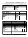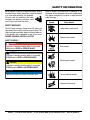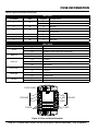
1
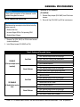
SETUP, ADJUSTMENTS AND CALIBRATIONS SERIES MODEL HTXD6i/STXD6i HYDRAULIC RIDE-ON TROWEL (YANMAR 4TNV84T-Z-DSA2 DIESEL ENGINE) Revision #2 (04/09/14) To find the latest revision of this publication, visit our website at: www.multiquip.com THIS MANUAL MUST ACCOMPANY THE EQUIPMENT AT ALL TIMES. PN: 32399 TABLE OF CONTENTS HTX6Di/STX6Di Trowel Machine Information And Maintenance Log............. 3 Safety Information................................................. 4-9 Tools Needed.......................................................... 10 Machine Information............................................... 11 Model................................................................... 11 Serial Number..................................................... 11 Program ID.......................................................... 11 General Procedures............................................... 12 Setup Jumper Installation.................................... 12 Remove Setup Jumper (If Installed).................... 12 Initial Check And Adjustments........................... 13-14 Preliminary Charge Pressure Adjustment .......... 13 Oil And Coolant Check........................................ 13 Hydraulic Oil Check.......................................... 13 Engine Oil ........................................................ 13 Engine Coolant................................................. 14 Service Tool Setup And Connection.................. 15-16 Whiteman Service Tool (WST) Installation.......... 15 Laptop Configuration.............................................. 17 Connection Procedure......................................... 17 Machine Setup And Calibration......................... 18-27 Calibrate Foot Pedal............................................ 18 Calibration........................................................ 19 Secondary Hydraulic Fill Procedures.................. 19 Machine Pressure Adjustment............................ 20 Charge Pressure Adjustment .......................... 20 Pitch Pressure Check....................................... 20 Pitch Pressure Adjustment............................... 21 Steering Pressure Adjustment.......................... 21 Trowel Speed Adjustment\Setup ........................ 22 Adjust Zero Stroke Position.............................. 22 Left Side Trowel Speed Adjustment.................. 22 Right Side Trowel Speed Adjustment................ 23 Calibrate Stroke Sensor................................... 23 Pitch Setup.......................................................... 24 Flatten Blades ................................................. 24 Measure Blade Leading Edge Height............... 25 Leading Edge Height Adjustment .................... 25 Set Zero Pitch Cylinder Stops.......................... 26 Pitch Sensor Calibration................................... 26 Inspection.......................................................... 28-29 Fluid Levels......................................................... 28 Mechanical.......................................................... 28 Static Blade Pitch Drift Test................................. 29 Fuse Information..................................................... 30 PAGE 2 — HTXD6i/STXD6i TROWEL • SETUP, ADJUSTMENTS AND CALIBRATIONS — REV. #2 (04/09/14) MACHINE INFORMATION AND MAINTENANCE LOG Technician__________________________________e Date:___________________________ Machine Information MODEL LH Motor Serial No. Machine Serial No. RH Motor Serial No. Engine Serial No. Program ID Pump Serial No. Program Version Machine Setup and Calibration Information Hydraulic Pressure Settings (Hydraulic Oil Temperature Below 125 °F) Calibration Charge Pressure (psi) Foot Pedal Pitch Pressure (psi) Stroke Sensor Steering Pressure (psi) Pitch Sensors Blade Speed Travel (LH) Left (rpm) Travel (RH) Right (rpm) Stops (LH) Point 1 Point 2 Stops (RH) Inspection Fuel Levels ü Leak Checks Engine Oil Engine Coolant Coolant Hydraulic Oil Hydraulics Mechanical ü Functional Checks Grease Points Hour Meter Stabilizer Rings Seat Switch Hydraulics Drift Test Retardant Spray System Travel (Start/Stop) Electrical Cooling Fan ü ü ü Initial Height (LH/RH) Final Height (LH/RH) Switches Lights and Indicators HTXD6i/STXD6i TROWEL • SETUP, ADJUSTMENTS AND CALIBRATIONS — REV. #2 (04/09/14) — PAGE 3 SAFETY INFORMATION Do not operate or service the equipment before reading the entire manual. Safety precautions should be followed at all times when operating this equipment. Failure to read and understand the safety messages and operating instructions could result in injury to yourself and others. Potential hazards associated with the operation of this equipment will be referenced with hazard symbols which may appear throughout this manual in conjunction with safety messages. Symbol Safety Hazard SAFETY MESSAGES The four safety messages shown below will inform you about potential hazards that could injure you or others. The safety messages specifically address the level of exposure to the operator and are preceded by one of four words: DANGER, WARNING, CAUTION or NOTICE. Lethal exhaust gas hazards Explosive fuel hazards SAFETY SYMBOLS DANGER Indicates a hazardous situation which, if not avoided, WILL result in DEATH or SERIOUS INJURY. Burn hazards WARNING Indicates a hazardous situation which, if not avoided, COULD result in DEATH or SERIOUS INJURY. CAUTION Rotating parts hazards Indicates a hazardous situation which, if not avoided, COULD result in MINOR or MODERATE INJURY. NOTICE Addresses practices not related to personal injury. Pressurized fluid hazards Hydraulic fluid hazards PAGE 4 — HTXD6i/STXD6i TROWEL • SETUP, ADJUSTMENTS AND CALIBRATIONS — REV. #2 (04/09/14) SAFETY INFORMATION GENERAL SAFETY CAUTION NEVER operate this equipment without proper protective clothing, shatterproof glasses, respiratory protection, hearing protection, steel-toed boots and other protective devices required by the job or city and state regulations. Avoid wearing jewelry or loose fitting clothes that may snag on the controls or moving parts as this can cause serious injury. NEVER operate this equipment when not feeling well due to fatigue, illness or when under medication. NEVER operate this equipment under the influence of drugs or alcohol. NOTICE This equipment should only be operated by trained and qualified personnel 18 years of age and older. Whenever necessary, replace nameplate, operation and safety decals when they become difficult read. Manufacturer does not assume responsibility for any accident due to equipment modifications. Unauthorized equipment modification will void all warranties. NEVER use accessories or attachments that are not recommended by Multiquip for this equipment. Damage to the equipment and/or injury to user may result. ALWAYS know the location of the nearest fire extinguisher. ALWAYS know the location of the nearest first aid kit. ALWAYS know the location of the nearest phone or keep a phone on the job site. Also, know the phone numbers of the nearest ambulance, doctor and fire department. This information will be invaluable in the case of an emergency. ALWAYS clear the work area of any debris, tools, etc. that would constitute a hazard while the equipment is in operation. No one other than the operator is to be in the working area when the equipment is in operation. DO NOT use the equipment for any purpose other than its intended purposes or applications. HTXD6i/STXD6i TROWEL • SETUP, ADJUSTMENTS AND CALIBRATIONS — REV. #2 (04/09/14) — PAGE 5 SAFETY INFORMATION TROWEL SAFETY NOTICE ALWAYS keep the machine in proper running condition. DANGER Engine fuel exhaust gases contain poisonous carbon monoxide. This gas is colorless and odorless, and can cause death if inhaled. The engine of this equipment requires an adequate free flow of cooling air. NEVER operate this equipment in any enclosed or narrow area where free flow of the air is restricted. If the air flow is restricted it will cause injury to people and property and serious damage to the equipment or engine. DANGEROUS GAS FUMES NEVER operate the equipment in an explosive atmosphere or near combustible materials. An explosion or fire could result causing severe bodily harm or even death. WARNING If applicable, NEVER use your hand to find hydraulic leaks. Use a piece of wood or cardboard. Hydraulic fluid injected into the skin must be treated by a knowledgable physician immediately or severe injury or death can occur. ALWAYS keep clear of rotating or moving parts while operating the trowel. NEVER disconnect any emergency or safety devices. These devices are intended for operator safety. Disconnection of these devices can cause severe injury, bodily harm or even death. Disconnection of any of these devices will void all warranties. CAUTION NEVER allow passengers or riders on the trowel during operation. NEVER lubricate components or attempt service on a running machine. NEVER place your feet or hands inside the guard rings while starting or operating this equipment. Fix damage to machine and replace any broken parts immediately. ALWAYS store equipment properly when it is not being used. Equipment should be stored in a clean, dry location out of the reach of children and unauthorized personnel. A safety manual for operating and maintenance personnel of concrete power trowels produced by the Association of Equipment Manufacturers (AEM) can be obtained for a fee by ordering through their website at www.aem.org. Order FORM PT-160 ENGINE SAFETY WARNING DO NOT place hands or fingers inside engine compartment when engine is running. NEVER operate the engine with heat shields or guards removed. Keep fingers, hands hair and clothing away from all moving parts to prevent injury. DO NOT remove the radiator cap while the engine is hot. High pressure boiling water will gush out of the radiator and severely scald any persons in the general area of the trowel. DO NOT remove the coolant drain plug while the engine is hot. Hot coolant will gush out of the coolant tank and severely scald any persons in the general area of the trowel. DO NOT remove the engine oil drain plug while the engine is hot. Hot oil will gush out of the oil tank and severely scald any persons in the general area of the trowel. CAUTION NEVER touch the hot exhaust manifold, muffler or cylinder. Allow these parts to cool before servicing equipment. PAGE 6 — HTXD6i/STXD6i TROWEL • SETUP, ADJUSTMENTS AND CALIBRATIONS — REV. #2 (04/09/14) SAFETY INFORMATION NOTICE NEVER run engine without an air filter or with a dirty air filter. Severe engine damage may occur. Service air filter frequently to prevent engine malfunction. NEVER tamper with the factory settings of the engine or engine governor. Damage to the engine or equipment can result if operating in speed ranges above the maximum allowable. FUEL SAFETY DANGER BATTERY SAFETY DANGER DO NOT drop the battery. There is a possibility that the battery will explode. DO NOT expose the battery to open flames, sparks, cigarettes, etc. The battery contains combustible gases and liquids. If these gases and liquids come into contact with a flame or spark, an explosion could occur. WARNING DO NOT start the engine near spilled fuel or combustible fluids. Fuel is extremely flammable and its vapors can cause an explosion if ignited. ALWAYS wear safety glasses when handling the battery to avoid eye irritation. The battery contains acids that can cause injury to the eyes and skin. ALWAYS refuel in a well-ventilated area, away from sparks and open flames. Use well-insulated gloves when picking up the battery. ALWAYS use extreme caution when working with flammable liquids. ALWAYS keep the battery charged. If the battery is not charged, combustible gas will build up. DO NOT fill the fuel tank while the engine is running or hot. DO NOT charge battery if frozen. Battery can explode. When frozen, warm the battery to at least 61°F (16°C). DO NOT overfill tank, since spilled fuel could ignite if it comes into contact with hot engine parts or sparks from the ignition system. ALWAYS recharge the battery in a well-ventilated environment to avoid the risk of a dangerous concentration of combustible gases. Store fuel in appropriate containers, in well-ventilated areas and away from sparks and flames. NEVER use fuel as a cleaning agent. If the battery liquid (dilute sulfuric acid) comes into contact with clothing or skin, rinse skin or clothing immediately with plenty of water. DO NOT smoke around or near the equipment. Fire or explosion could result from fuel vapors or if fuel is spilled on a hot engine. If the battery liquid (dilute sulfuric acid) comes into contact with eyes, rinse eyes immediately with plenty of water and contact the nearest doctor or hospital to seek medical attention. CAUTION ALWAYS disconnect the NEGATIVE battery terminal before performing service on the equipment. ALWAYS keep battery cables in good working condition. Repair or replace all worn cables. HTXD6i/STXD6i TROWEL • SETUP, ADJUSTMENTS AND CALIBRATIONS — REV. #2 (04/09/14) — PAGE 7 SAFETY INFORMATION TRANSPORTING SAFETY CAUTION NEVER allow any person or animal to stand underneath the equipment while lifting. Ride-on trowels are very heavy and awkward to move around. Use proper heavy lifting procedures and DO NOT attempt to lift the trowel by the guard rings. NOTICE The easiest way to lift the trowel is to utilize the lift loops that are welded to the frame. These lift loops are located to the left and right sides of the operator’s seat. A strap or chain can be attached to these lift loops, allowing a forklift or crane to lift the trowel up onto and off of a slab of concrete. The strap or chain should have a minimum of 2,000 pounds (1,000 kg) lifting capacity and the lifting gear must be capable of lifting at least this amount. NEVER transport trowel with float pans attached unless safety catches are used and are specifically cleared for such transport by the manufacturer. NEVER hoist the trowel more than three feet off the ground with float pans attached. Before lifting, make sure that the lift loops are not damaged. TOWING SAFETY CAUTION Check with your local county or state safety towing regulations, in addition to meeting Department of Transportation (DOT) Safety Towing Regulations, before towing your trowel. In order to reduce the possibility of an accident while transporting the trowel on public roads, ALWAYS make sure the trailer that supports the trowel and the towing vehicle are mechanically sound and in good operating condition. ALWAYS shutdown engine before transporting Make sure the hitch and coupling of the towing vehicle are rated equal to, or greater than the trailer “gross vehicle weight rating.” ALWAYS inspect the hitch and coupling for wear. NEVER tow a trailer with defective hitches, couplings, chains, etc. Check the tire air pressure on both towing vehicle and trailer. Trailer tires should be inflated to 50 psi cold. Also check the tire tread wear on both vehicles. ALWAYS make sure the trailer is equipped with a safety chain. ALWAYS properly attach trailer’s safety chains to towing vehicle. Always make sure crane or lifting device has been properly secured to the lift loops of the equipment. ALWAYS make sure the vehicle and trailer directional, backup, brake and trailer lights are connected and working properly. ALWAYS shutdown engine before transporting. DOT Requirements include the following: NEVER lift the equipment while the engine is running. • Connect and test electric brake operation. Tighten fuel tank cap securely and close fuel cock to prevent fuel from spilling. • Secure portable power cables in cable tray with tie wraps. Use adequate lifting cable (wire or rope) of sufficient strength. The maximum speed for highway towing is 55 MPH unless posted otherwise. Recommended off-road towing is not to exceed 15 MPH or less depending on type of terrain. DO NOT lift machine to unnecessary heights. ALWAYS tie down equipment during transport by securing the equipment with rope. Avoid sudden stops and starts. This can cause skidding, or jack-knifing. Smooth, gradual starts and stops will improve towing. Avoid sharp turns to prevent rolling. PAGE 8 — HTXD6i/STXD6i TROWEL • SETUP, ADJUSTMENTS AND CALIBRATIONS — REV. #2 (04/09/14) SAFETY INFORMATION Trailer should be adjusted to a level position at all times when towing. Raise and lock trailer wheel stand in up position when towing. Place chock blocks underneath wheel to prevent rolling while parked. Place support blocks underneath the trailer’s bumper to prevent tipping while parked. Use the trailer’s swivel jack to adjust the trailer height to a level position while parked. ENVIRONMENTAL SAFETY NOTICE Dispose of hazardous waste properly. Examples of potentially hazardous waste are used motor oil, fuel and fuel filters. DO NOT use food or plastic containers to dispose of hazardous waste. DO NOT pour waste, oil or fuel directly onto the ground, down a drain or into any water source. HTXD6i/STXD6i TROWEL • SETUP, ADJUSTMENTS AND CALIBRATIONS — REV. #2 (04/09/14) — PAGE 9 TOOLS NEEDED The specialized tools listed in Table 1 are required to maintain and service the HTXD6i and STXD6i ride-on trowels. Fleet technicians and servicing dealers must have these tools for efficient unit setup and component calibration. TOOL Table 1. Setup, Calibration, and Diagnostic Tools DESCRIPTION PART NO. QTY Includes all tools listed below. 32061 1 CAN Gateway Cable Required to interface to the trowel MCU. Required for foot pedal calibration, pitch sync calibration, stroke cylinder calibration, engine fault code reading, diagnostics, ETC. 22882 1 Gauge Tool (3.25”) Used in calibrating one of the two blade pitch set points as part of the synchronization process. 32044 2 Gauge Tool (2.25”) Used in calibrating one of the two blade pitch set points as part of the synchronization process. 32000 2 Set Up Jumper Used to place the engine at full speed for component calibration and to simultaneously disable both the stroke follower and cold start mode. 32007 1 Pedal Wrench Used to help set the foot pedal sensor. It is also used for setting the Zero Pitch Cylinder Stops by using the thickness of the wrench. 32020 1 Tool Kit PAGE 10 — HTXD6i/STXD6i TROWEL • SETUP, ADJUSTMENTS AND CALIBRATIONS — REV. #2 (04/09/14) MACHINE INFORMATION NOTICE The following machine information should be recorded on Machine Information and Maintenance Log for unit service tracking and for filing any warranty claims. 4. Pump Serial Number — located on sticker on pump (Figure 3). The lower number is the pump serial number. MODEL 1. Enter appropriate model: HTXD6i — for 6-blade HTX STXD6i — for 6-blade STX SERIAL NUMBER 2. Machine Serial Number — as shown on serial tag. 3. Engine Serial Number — located on top of engine (E/N) (Figure 1) or stamped on side of block (Figure 2). Figure 3. Pump Serial Number Location 5. Motor Serial Number — located on sticker on top of hydraulic motors (Figure 4).The lower number is the motor serial number. NOTICE If lot number is listed instead of the serial number, record lot number. Figure 1. Engine Serial Number Location 1 Figure 4. Motor Serial Number Location Figure 2. Engine Serial Number Location 2 HTXD6i/STXD6i TROWEL • SETUP, ADJUSTMENTS AND CALIBRATIONS — REV. #2 (04/09/14) — PAGE 11 GENERAL PROCEDURES NOTICE These general procedures will be referenced in other sections throughout the manual. SETUP JUMPER INSTALLATION REMOVE SETUP JUMPER (If installed). 1. Remove Setup Jumper (P\N: 32007) from P24 of main harness. 2. Re-install Cap (P\N: 22812) on P24 of main harness. NOTICE Machine must be secured prior to installation. Installing setup jumper will: •Disable Cold Start •Increase Engine RPM to Full operating RPM •Disable Stroke Follower 1. Remove Cap (P\N: 22812) on P24 of main harness (under foot platform). 2. Install Setup Jumper (P/N: 32007 on P24). DISABLE (If Setup Jumper is not installed) RE-ENABLE (If disabled via service tool) Table 2. Disable and Re-enable Options 1. Open service tool. 2. Click “machine setup” button on main page. Cold Start 3. Click “Cold Start” button under Setup Menu. 4. Click check box next to Disabled. 5. Press Download Button. 1. Open service tool. 2. Click “machine setup” button on main page. Stroke Follower 3. Click “Stroke Cont.” button under Setup Menu. 4. Click button “Disable Stroke Follower”. 1. Open service tool. 2. Click “machine setup” button on main page. 3. Click “Cold Start” button under Setup Menu. Cold Start 4. Uncheck box next to Disable. 5. Press Download Button. 1. Open service tool. 2. Click “machine setup” button on main page. Stroke Follower 3. Click “Stroke Cont.” button under Setup Menu. 4. Click button “Enable Stroke Follower”. PAGE 12 — HTXD6i/STXD6i TROWEL • SETUP, ADJUSTMENTS AND CALIBRATIONS — REV. #2 (04/09/14) INITIAL CHECK AND ADJUSTMENTS PRELIMINARY CHARGE PRESSURE ADJUSTMENT OIL AND COOLANT CHECK Hydraulic Oil Check NOTICE Skipping this step during initial set-up may cause machine to inadvertently move during further steps, due to insufficient charge pressure. 1. Make sure the machine is cold. 2. Remove the starwheel cap (Figure 6) and visually check oil level. 1. Loosen 1-1/16" jam nut on charge relief valve (Item A, Figure 5). 3. Make sure that it is filled to the red line as shown in Figure 6. 2. Use a 1/2" socket to adjust the small hex nut within the larger hex jam nut (Item B, Figure 5). 4. Put back and tighten starwheel cap after checking or filling. 3. Rotate small hex nut (Item B, Figure 5) clockwise until bottomed out. DO NOT overtighten. NOTICE The sight glass is only used to check the fluid condition (dirt or air bubbles) and not to check the oil level. REMOVE STARWHEEL CAP TO CHECK OIL LEVEL A B Figure 5. Preliminary Charge Pressure Adjustment FLUID CONDITION SIGHT GLASS OIL LEVEL (FULL) Figure 6. Oil Level Check HTXD6i/STXD6i TROWEL • SETUP, ADJUSTMENTS AND CALIBRATIONS — REV. #2 (04/09/14) — PAGE 13 INITIAL CHECK AND ADJUSTMENTS Engine Oil Engine Coolant 1. Ensure engine is level. 1. Verify that the radiator drain cock is closed. 2. Remove the oil filler cap (top or side). See Figure 7. 2. Remove radiator cap. ENGINE OIL FILLER CAP 3. Pour engine coolant slowly into the radiator until it is even with the lip of the engine coolant filler port (Figure 8). DIPSTICK FULL ADD OIL F L ENGINE OIL FILLER CAP Figure 7. Adding Engine Oil 3. Add the required amount of engine oil at the top or side engine oil filler port. 4. Wait 3 minutes then proceed with next step. 5. Remove dipstick and wipe clean with cloth. Figure 8. Adding Engine Coolant 4. Reinstall radiator cap. 5. Remove the cap on the reservoir tank. 6. Fill to the low mark (Cold Mark) with engine coolant (Figure 9). 6. Fully reinsert dipstick. 7. Remove the dipstick. The oil level should be between the upper and lower) lines on the dipstick. 8. Add more oil if necessary and repeat steps 4 to 7. 9. Reinstall the oil cap and hand tighten. Over-tightening may damage the cap. Figure 9. Reservoir Tank PAGE 14 — HTXD6i/STXD6i TROWEL • SETUP, ADJUSTMENTS AND CALIBRATIONS — REV. #2 (04/09/14) SERVICE TOOL SETUP AND CONNECTION WHITEMAN SERVICE TOOL (WST) INSTALLATION NOTICE 7. Double-click on the 22708P Icon on your desktop. One of the screens shown in Figure 11 will appear. Click "Cancel". Make sure that the Sauer Danfoss Plus Software is already installed before proceeding with the Whiteman Service Tool (WST) installation. 1. Call or e-mail Multiquip Technical Support or Field Service to obtain the application specific Whiteman Service Tool (WST) file. 2. Also obtain software license key through Multiquip Technical Support or Field Service. 3. The WST file will be sent to you as an attachment to an e-mail. 4. Open the e-mail sent by Multiquip and click on the – Whiteman Service Tool attachment. On the drop-down menu, select "Save Navigation Bar is not populated Click “Cancel” Target As" (Figure 10). n Application File e file rop select t As “. Navigation Bar Click Application “Cancel” Whiteman Service Tool is not populated Connecting Laptop to TrowelBar (Not Populated) Figure 11. WST Navigation to the tion. • After canceling from previous screen, this screen new screen 8. Click "Cancel" again when the new (Figurewill 12) open but the navigation bar is populated. comes up. ge the Figure 10. Saving WST Application File 5. Do not change the file name. Save the file to your your computers desktop. desktop. 6. Locate and verify that the WST application file (22708P) was saved to your desktop. 20 Click cancel Figure 12. WST Navigation Bar (Populated) HTXD6i/STXD6i TROWEL • SETUP, ADJUSTMENTS AND CALIBRATIONS — REV. #2 (04/09/14) — PAGE 15 SERVICE TOOL SETUP AND CONNECTION Whiteman Service Tool Application 9. The new screen both navigation and tool bars Connecting Laptopwilltohave Trowel (Figure 13.) screen, this new screen will Afteractive canceling from previous • open with full Navigation and tool bars active.. 21 Figure 13. WST Tool Bar an Service ToolOn the Application 10. Click on "Tools". drop-down menu, click on "License Manager" (Figure 14). Laptop to Trowel all Whiteman Service Tool Application Connecting Laptop to Trowel • • Figure 14. WST License Manager License Key Install Click on License 11. Input the license Manager key obtained from Multiquip (Figure 15) and click "OK". se key and click OK. • 22 Input youFigure license key click OK. 15.andEntering License Key PAGE 16 — HTXD6i/STXD6i TROWEL • SETUP, ADJUSTMENTS AND CALIBRATIONS — REV. #2 (04/09/14) LAPTOP CONFIGURATION CONNECTION PROCEDURE NOTICE 4. When the CAN Gateway cable is connected to the laptop for the first time, it is necessary to install the CAN driver software. The installation screen will appear (Figure 19). Click "Next" to install the software automatically (default). WST – Whiteman Service Tool Make sure that the Sauer Danfoss Plus Software and Whiteman Service Tool (WST) are installed before proceeding with the connection procedure. 1. Connecting Laptop to WST – Whiteman Plug the CAN Gateway Trowel cable to the trowel at the service port (Figure 16). Do not connect laptop at this time. Connecting Laptop to • First time connected. Trowel • CAN Driver Software install. • First time connected. • CAN Driver Software install. Figure 19. CAN Driver Installation 5. Click "Finish" on the next screen (Figure 20) to complete installation. Figure 16. CAN Gateway Cable to Service Port • Service Service Toolignition Application 2.Whiteman On the trowel, turn the key to the ON position Connecting Trowel (FigureLaptop 17). toThis will turn on the MCU. It is not Turn the Key to the ONto position, or turning on the necessary crankCranking or turn on the engine. engine is not required. 26 OFF ACC ON CRANK 26 Figure 20. CAN Driver Installation Complete 24 Figure 17. Ignition Key ON WST – Whiteman Service 6. On the Service Tool software on Tool your laptop, the main screen to should show Firmware info loaded from trowel Connecting Laptop Trowel 3. Connect the USB connector of the CAN Gateway cable to the USB port (Figure 18). • Main Screen • Firmware info is loaded from MCU • Machine Status box shows LAMPS lit. Figure 18. Connecting the Laptop 27 MCU and the Machine Status box shows lamps lit (Figure 21). Figure 21. Service Tool Main Screen HTXD6i/STXD6i TROWEL • SETUP, ADJUSTMENTS AND CALIBRATIONS — REV. #2 (04/09/14) — PAGE 17 MACHINE SETUP AND CALIBRATION CALIBRATE FOOT PEDAL 1. Turn key to ON position but DO NOT start machine. 2. Click “CALIBRATION” button on machine setup page. 3. Click “CALIBRATION” button in "PEDAL SENSOR" frame (Figure 22). Sensor Adjustment NOTICE If sensor is preset, during assembly, with P\N: 32020, WRENCH, PEDAL SETUP, this step may be skipped. 1. Read % sensor voltage. If 15% to 25%, skip to calibration section. Otherwise, continue with next step to adjust sensor (Figure 23). Figure 22. Calibration Button NOTICE Prior to calibration of the foot pedal sensor, ensure the mechanical movement is not restricted. It should smoothly depress to the hard stop and smoothly return to full released position. Figure 23. % Sensor Voltage 2. Using 7/16 wrench, rotate foot pedal shaft (Item B, Figure 24) , while holding foot pedal lever (Item A, Figure 24) in upright position, until % sensor voltage is 15% to 25%. NOTICE This may require loosening of jamb nuts. 3. Verify that jamb nuts are tight (Item C, Figure 24) B A C A Figure 24. Sensor Adjustment PAGE 18 — HTXD6i/STXD6i TROWEL • SETUP, ADJUSTMENTS AND CALIBRATIONS — REV. #2 (04/09/14) MACHINE SETUP AND CALIBRATION Calibration 1. Set sensor zero position default: a. Ensure that foot pedal is fully released. b. Read % SENSOR VOLTAGE. c. Round % Sensor Voltage value to nearest percent and enter in CALB POINT 1 DEFAULT. d. Press "Download" button to update value in MCU. 2. Set sensor full position default: a. Fully depress pedal. b. Read % Sensor Voltage (Figure 25). c. Round value to nearest percent and enter in CALB POINT 2 DEFAULT. d. Press "Download button" to update value in MCU. SECONDARY HYDRAULIC FILL PROCEDURES NOTICE Once the oil heats up, any oil expansion will go up the overflow hose and into the fluid expansion tank. Removing the oil fill cap, once the fluid is at operating temperature, will cause fluid loss as the expansion will cause oil to spill out. 1. Elevate machine so blades are no longer contacting floor. 2. Start the unit and run the engine. 3. Check level while machine is cold. 4. Remove the starwheel cap (Figure 6) and visually check oil level. 5. Fill as needed so oil is at the top line of the reservoir (red line in Figure 26) and that the oil level cannot be seen in the fluid condition sight glass. REMOVE STARWHEEL CAP TO CHECK OIL LEVEL Figure 25. Start Pedal Sensor Calibration 3. Press “START” button to begin calibration and follow prompts. 4. Once calibrated, move pedal thru range, ensuring calibrated signal moves from 0 to 100%. 5. Record Calibration Values on Machine Information and Maintenance Log. FLUID CONDITION SIGHT GLASS OIL LEVEL (FULL) Figure 26. Checking Oil Level 6. Put back and tighten starwheel cap after filling. 7. Turn off machine and lower. HTXD6i/STXD6i TROWEL • SETUP, ADJUSTMENTS AND CALIBRATIONS — REV. #2 (04/09/14) — PAGE 19 MACHINE SETUP AND CALIBRATION MACHINE PRESSURE ADJUSTMENT NOTICE 5. Loosen 1-1/16" jam nut on charge relief valve (Item A, Figure 28). All pressures to be adjusted with machine at full engine RPM. To adjust pressures, cold start must be disabled through the Whiteman Service Tool (WST). A Charge Pressure Adjustment NOTICE DO NOT depress the foot pedal with the 300-600 PSI gauge installed. Immediate damage to the gauge will occur. Cold start must be disabled. Failure to do so will cause immediate damage to the gauge. 1. Disable cold start. 2. With machine off, install gauge capable of reading 300 psi to Charge Or Pitch pressure test port (Figure 27). B Figure 28. Charge Pressure Adjustment 6. Using a 1/2" socket, adjust the small hex nut within the larger hex jam nut (Item B, Figure 28). 7. Adjust to proper charge pressure: 300 ±25 psi. 8. Record pressure on Machine Information and Maintenance Log. 9. Retighten jam nut. 10. Return engine rpm to idle. 11. Turn off machine and remove gauge. Pitch Pressure Check 1. Disable cold start. Figure 27. Pressure Test Ports Location 3. Restart machine. 4. Increase engine rpm to full operating RPM (an operator must be present on the seat to reach full engine speed). 2. Install a 3000 PSI range pressure gauge to Charge or Pitch pressure test port (Figure 27). 3. Start machine and increase engine rpm to full operating RPM. 4. Activate left pitch switch. 5. Flatten blades (bottom out the pitch cylinders). 6. Continue to hold down pitch switch and measure pressure. If pressure is within range (1850 PSI to 2000 PSI), no adjustment is required. If pressure in not within range, proceed to Pitch Pressure Adjustment section. 7. If no adjustment is required, record pressure on Machine Information and Maintenance Log. PAGE 20 — HTXD6i/STXD6i TROWEL • SETUP, ADJUSTMENTS AND CALIBRATIONS — REV. #2 (04/09/14) MACHINE SETUP AND CALIBRATION 8. Return engine rpm to idle. 9. Turn off machine and remove gauge. Pitch Pressure Adjustment 1. Disable cold start. 1. Increase engine rpm to full operating RPM. 2. Loosen 3/4" jam nut on pitch relief valve (Figure 29). Steering Pressure Adjustment NOTICE DO NOT depress the foot pedal with the 300-600 PSI gauge installed. Immediate damage to the gauge will occur. 1. Disable cold start. 2. Install a 300 or 600 PSI gauge on steering pressure port (Figure 27). 3. Start machine. 4. Increase engine rpm to full operating RPM. 5. Loosen 3/4" jam nut on steering valve (Figure 30). 3/4-INCH JAM NUT 1/4-INCH HEX NUT Figure 29. Pitch Pressure Adjustment 3. Using a 1/4" allen wrench, adjust the small hex nut within the larger hex jam nut. STEERING VALVE ADJUSTMENT SCREW 4. Tighten 3/4" jam nut. 5. Check the pressure as described earlier (see Pitch Pressure Check section). 6. If pressure requires further adjustment, repeat steps 2 through 4 until pressure check reads 1850 ± 50 PSI. 7. Record pressure on Machine Information and Maintenance Log. 8. Return machine engine rpm to idle. 9. Turn off machine and remove gauge. Figure 30. Steering Pressure Adjustment 6. Using a 1/4" allen wrench, adjust the small hex nut within the larger hex jam nut. 7. Adjust to proper steering pressure: •HTXD6i: 245 psi ± 10 psi (Cold Oil) 235 psi ± 10 psi (Hot Oil) •STXD6i: 300 psi ± 10 psi (Cold Oil) 290 psi ± 10 psi (Hot Oil) HTXD6i/STXD6i TROWEL • SETUP, ADJUSTMENTS AND CALIBRATIONS — REV. #2 (04/09/14) — PAGE 21 MACHINE SETUP AND CALIBRATION 8. Retighten jam nut. 5. Lower trowel and shut off. 9. Return engine to idle. 6. Loosen Jamb nut (Item D, Figure 31). 10. Turn off machine and remove gauge. 7. Remove retaining screw (Item C, Figure 31). The spacer (Item A, Figure 31) will also come off. 11. Record Pressure on Machine Information and Maintenance Log. 12. Re-enable cold start. TROWEL SPEED ADJUSTMENT\SETUP CAUTION Machine movement will occur during this step. Ensure machine is secure or operator is present in seat. All guards should be in place. Keep fingers, hands, hair, and clothing away from all moving parts to prevent injury. Adjust Zero Stroke Position 8. Turn rod end (Item B, Figure 31) in, shortening overall length of cylinder assembly. 9. Reinstall retaining screw (Item C, Figure 31) and spacer (Item A, Figure 31). Apply blue loctite to make sure screw will not come off. 10. Tighten jamb nut (Item D, Figure 31). 11. Restart machine and repeat steps 2 thru 8 as necessary, until blades no longer spin. Left Side Trowel Speed Adjustment NOTICE 1. Start machine. Stroke sensor must be recalibrated after trowel speed adjustment for proper machine operation. 2. Ensure trowel is running at idle with no stroke. On a cold trowel, the unit will go into cold start mode and not be at idle. To place the trowel at idle speed, disable cold start with the WST. 1. Install setup jumper or disable stroke follower. 3. Elevate machine so blades are no longer contacting floor. Make sure to follow proper lifting procedures. Refer to Lifting Safety Information section. 3. Fully depress pedal and measure Left Side Trowel Speed. 4. Ensure blades are not rotating. If rotating, continue to next step and adjust per instructions. Otherwise, set trowel on ground and verify jamb nut (Item D, Figure 31) is tight then continue to next section (Left Side Trowel Speed Adjustment). 2. Start machine, on bare floor and pitch until blade tips are about ½” off the ground. 4. Adjust speed limit screw and tighten jamb nut (Figure 32). C Figure 32. Left Side Trowel Speed Adjustment E D A B Figure 31. Zero Stroke Position Adjustment PAGE 22 — HTXD6i/STXD6i TROWEL • SETUP, ADJUSTMENTS AND CALIBRATIONS — REV. #2 (04/09/14) MACHINE SETUP AND CALIBRATION 5. Re-measure speed, repeating steps 2 and 3 until Left Side Trowel Speed is correct: a. HTXD6i — 157 to 160 RPM (942 to 960 Pulses per minute) b. STXD6i— 127 to 130 RPM (762 to 780 Pulses per minute) Calibrate Stroke Sensor CAUTION Machine movement will occur during this step. Ensure machine is secure or operator is present in seat. All guards should be in place. Keep fingers, hands, hair, and clothing away from all moving parts to prevent injury. 6. Record L.H. speed on Machine Information and Maintenance Log in machine setup area. 1. Turn machine off for at least 10 seconds. Right Side Trowel Speed Adjustment 2. Restart machine. NOTICE Stroke sensor must be recalibrated after trowel speed adjustment for proper machine operation. The trowel speeds should be adjusted on a dry concrete floor with the blades pitched slightly (tips about 1/2” off ground). 3. Install Setup Jumper or disable Stroke Follower. 4. Click “Calibration” button on machine setup page. 5. Click “Calibration” button in STROKE SENSOR section (Figure 34). 1. Verify setup jumper is installed or stroke follower is disabled. 2. Fully depress pedal, measure Left Side and Right Side Trowel Speed. 3. Adjust trowel arm connecting rod on the pump actuating lever and tighten jamb nuts (Figure 33). Figure 34. Calibrate Stroke Sensor Figure 33. Adjusting Right Side Trowel Speed 4. Re-measure speed and repeat steps 2 and 3 until Left Side and Right side are within 1 RPM of each other. 5. Record R.H. speed on Machine Information and Maintenance Log in Machine Setup section. 6. Remove setup jumper or re-enable stroke follower. HTXD6i/STXD6i TROWEL • SETUP, ADJUSTMENTS AND CALIBRATIONS — REV. #2 (04/09/14) — PAGE 23 MACHINE SETUP AND CALIBRATION 6. Set Sensor zero position default: a. Ensure foot pedal is fully released. b. Read % Sensor Voltage (Figure 35). PITCH SETUP Prior to pitch setup, check and make sure that the following are in excellent condition to ensure eventual proper blade pitch synchronization and proper blade flatness. Blade condition - check for no excessive wear, new blades preferred Trowel arm bushings Pitch bolt adjustment for flatness Pitch bolt head for excessive wear Wear plate Thrust plate bearing and bushing - must lubricate Yoke for excessive wear CAUTION Figure 35. Start Stroke Sensor Calibration c. Round value to nearest percent and enter in CALB POINT 1 DEFAULT. d. Press "Download" button to update value in MCU. 7. Set Sensor full position default: a. Have an operator fully depress pedal and hold at full blade speed. b. Read % Sensor Voltage. c. Round value to nearest percent and enter in CALB POINT 2 DEFAULT. Machine movement will occur during this step. Ensure machine is secure or operator is present in seat. All guards should be in place. Keep fingers, hands, hair, and clothing away from all moving parts to prevent injury. Flatten Blades 1. Adjust blade pitch adjustment bolts as necessary to ensure machine operates smoothly (Figure 36). BLADE PITCH ADJUSTMENT BOLT d. Press "Download" button to update value in MCU. 8. The operator must be on the unit to drive and stroke the cylinder. Have a second person press the “START” button and indicate to the operator what the prompts are on the screen. The unit will be run from no stroke to fully stroked during this calibration. 9. After calibration sequence is completed, click "EXIT". 10. Once calibrated, the second person must move pedal thru range and the operator ensures stroke follows and calibrated signal moves from 0 to 100%. TROWEL LEVER SPIDER PLATE TROWEL ARM TROWEL BLADE Figure 36. Blade Pitch Adjustment PAGE 24 — HTXD6i/STXD6i TROWEL • SETUP, ADJUSTMENTS AND CALIBRATIONS — REV. #2 (04/09/14) MACHINE SETUP AND CALIBRATION Measure Blade Leading Edge Height 1. Fully pitch machine by pressing and holding Twin pitch up button until pitch cylinders fully extended. 3. Remove clevis pin (Item E, Figure 38). Loosen jamb nuts (Item C, Figure 38) and adjust clevis (Item D, Figure 38) to cylinder (Item A, Figure 38) position, to raise or lower pitch as required. 2. Choose a blade on both LH and RH Rotor. Using Gauge P/N 32044, measure height of raised leading edge ensuring it is 2.00” ±.060” (Figure 37). If the blade slides under the first step but not the next, it is within limits. A C D E Figure 38. Blade Leading Edge Height Adjustment Figure 37. Measuring Leading Edge Height Leading Edge Height Adjustment 1. If leading edge height is within limits (2.000” ± .060”) for left and right side, then no adjustment is needed. Otherwise, proceed to next step for adjustment. 4. Tighten jamb nuts(Item C, Figure 38) and reinstall clevis pin (Item E, Figure 38). 5. Re-measure as per instructions in “Measure Blade Leading Edge Height” section. 6. Repeat steps 2 thru 5 until Left and Right leading edge height are within limits. 2. Flatten blades (bottom out the pitch cylinders). HTXD6i/STXD6i TROWEL • SETUP, ADJUSTMENTS AND CALIBRATIONS — REV. #2 (04/09/14) — PAGE 25 MACHINE SETUP AND CALIBRATION Set Zero Pitch Cylinder Stops 1. Flatten blades (bottom out the pitch cylinders). 2. Turn machine off. 3. Remove clevis pin (Item E, Figure 39) from pitch cylinder allowing yoke (Item B, Figure 39) to rest on thrust collar. 1. Turn machine off for at least 10 seconds and then restart machine. 2. Click “Calibration” button on machine setup page. 3. Click “Calibration” button in Pitch Sensors section (Figure 40). C D B E Figure 40. Pitch Sensor Calibration 4. Press “zero” button (Figure 42) to begin calibration. 5. Set Calibration Point 1. Figure 39. Zero Pitch Adjustment 4. Loosen jam nut (Item C, Figure 39) with ¾” wrench. a. Press Hard Ext. button to fully extend pitch cylinders. 5. Set distance between head of stop (Item D, Figure 39) and yoke (Item B, Figure 39) to .075” (14 gauge steel, Gauge #32020). 6. Loctite and tighten jam nut (Item C, Figure 39). 7. Reinstall clevis pin (Item E, Figure 39) between pitch cylinder and yoke. Pitch Sensor Calibration CAUTION Machine movement will occur during this step. All guards should be in place. Keep fingers, hands, hair, and clothing away from all moving parts to prevent injury. NOTICE Pitch mode switch must be in the manual position. PAGE 26 — HTXD6i/STXD6i TROWEL • SETUP, ADJUSTMENTS AND CALIBRATIONS — REV. #2 (04/09/14) MACHINE SETUP AND CALIBRATION b. Install 3.25” Gauge (P/N 32044) over both Left and Right Cylinders as shown in Figure 41. g. Press Hard Ext. Button to fully extend pitch cylinders. h. Remove gauge. 3.25” GAUGE 6. Set Calibration Point 2. a. Install 2.25” Gauge P/N 32000 over both Left and Right Cylinders as shown in Figure 41. b. Press Hard Ret. Button to retract cylinder onto gauge. c. Verify gauge is tight between cylinder body and clevis. d. Press “Set T2” Button. e. Record values on Machine Information and Maintenance Log in Machine Setup section. f. Press Hard Ext. Button to fully extend pitch cylinders. g. Remove gauge. 7. Set Calibration Point 3. Figure 41. Gauge Installation c. Press Hard Ret. button to retract cylinder onto gauge. d. Verify gauge is tight between cylinder body and clevis. e. Press “Set T1” button (Figure 42). a. Ensure Hard Ext. is active and pitch cylinders are fully extended. b. Press “Set L1” button. c. Record values on Machine Information and Maintenance Log in Machine Setup section. 8. Set Calibration Point 4. a. Press Hard Ret. button to fully retract cylinders, ensure yoke is against zero pitch stop. b. Press Soft Ext. button, and wait until yoke is pressing against thrust collar. c. Press “Set L2” button. d. Record values on Machine Information and Maintenance Log in Machine Setup section. 9. Once calibrated, move pitch thru range ensuring calibrated signal moves from 0 to 100%. 10. Turn machine off for 10 seconds. Figure 42. Start Pitch Sensor Calibration f. Record values on Machine Information and Maintenance Log in Machine Setup section. HTXD6i/STXD6i TROWEL • SETUP, ADJUSTMENTS AND CALIBRATIONS — REV. #2 (04/09/14) — PAGE 27 INSPECTION FLUID LEVELS Record the following fluid levels on Machine Information and Maintenance Log in Inspection section. Refer to Fluid Fill and Check section for procedure. Engine Oil Engine Coolant Hydraulic Oil MECHANICAL 1. Grease Points — Ensure that the following Grease Points are greased, wiped down and capped: •Thrust Collar •Fingers 2. Stabilizer Rings a. Verify at least 1 thread is visible below lower bolt on all heim joints (Figure 43). 3. Hydraulics •Spot check paint marks on fittings. •Ensure that there are no leaks. 4. Retardant Spray System •Fill with water and perform operational check. •Verify no leaks. 5. Electrical (Cooling Fan) •Verify fan cycles on when key is turned on (will remain on for 10s). •Verify air flow direction is outward. 6. Lights •Verify operation of all 6 machine lights. 7. Switches •Verify proper operation of all switches. 8. Indicators •Verify illumination when key is turned on (will remain on for 10s) •Red Stop Lamp •Amber Warning Lamp •Pitch Mode Light •Cruise Control Light •Coolant Temp •Aux 1 •Aux 2 Figure 43. Visible Thread b. Verify heim joint is centered, and not rotated, when bolted on Figure 44). 9. Aesthetics •Paint Quality - No bare spots - No scratches •Decals - Readable -Not torn or scratched Figure 44. Heim Joint Orientation PAGE 28 — HTXD6i/STXD6i TROWEL • SETUP, ADJUSTMENTS AND CALIBRATIONS — REV. #2 (04/09/14) INSPECTION STATIC BLADE PITCH DRIFT TEST 1. Switch smart pitch switch to off position. 2. Bring machine up to temperature. This will be indicated by “Cold Start” (aux 1) lamp turning off. 3. Choose one blade from each spider and mark with small X to identify. 4. Using the Twin pitch button, cycle the blades from flat to full pitch 8 times leaving the blades in the full pitch position on the eighth cycle. 5. Turn the engine off, and record time and tip height on Machine Information and Maintenance Log. 6. Leave for a 3-hour test period then re-measure tip height. Record height and time on Machine Information and Maintenance Log. 7. Compare the two measurements. Drift exceeding 3/16” in three hours is unacceptable. HTXD6i/STXD6i TROWEL • SETUP, ADJUSTMENTS AND CALIBRATIONS — REV. #2 (04/09/14) — PAGE 29 FUSE INFORMATION Refer to Figure 45 for location on fuse panel. Table 3. Fuses Fuse Number Amps 1 20 2 20 3 5 4 Designator Functions Fused T13 MCU Power T21 Service Port Connector T3 Oil Cooler T5 Light Switch T15 Pitch Switches 20 T6 Left Lights 5 7.5 T23 Sprayers 6 20 T7 Right Lights Table 4. Ground Location Top Left Middle Left Bottom Left Bottom Right Middle Right Top Right Designator Functions Grounded T12 MCU T14 Pitch Switch, Throttle, Cruise, LED's, Cluster gauge T20 Service Port Connector T24 Spray Pumps T25 Rear Lights T26 Pitch Switch, Throttle, Cruise, LED's, Cluster gauge T28 Engine Harness T1 Pitch Valves T2 Control Relay T4 Cooler Fan T27 Front Right Lights T31 PRM (Power Relay Module) T32 Hour Meter FUSE PANEL TL GROUND ML BL FUSES TR MR GROUND 20 20 5 20 7.5 20 BR FUSES Figure 45. Fuse and Ground Location PAGE 30 — HTXD6i/STXD6i TROWEL • SETUP, ADJUSTMENTS AND CALIBRATIONS — REV. #2 (04/09/14) NOTES HTXD6i/STXD6i TROWEL • SETUP, ADJUSTMENTS AND CALIBRATIONS — REV. #2 (04/09/14) — PAGE 31 SETUP, ADJUSTMENTS AND CALIBRATIONS HERE’S HOW TO GET HELP PLEASE HAVE THE MODEL AND SERIAL NUMBER ON-HAND WHEN CALLING United StateS Multiquip Corporate Office 18910 Wilmington Ave. Carson, CA 90746 Contact: [email protected] MQ Parts Department Tel. (800) 421-1244 Fax (310) 537-3927 Service Department 800-421-1244 310-537-3700 800-427-1244 310-537-3700 Fax: 800-672-7877 Fax: 310-637-3284 Warranty Department Fax: 310-537-4259 800-421-1244 310-537-3700 Fax: 310-943-2249 Technical Assistance 800-478-1244 Fax: 310-943-2238 Canada United Kingdom Multiquip Multiquip (UK) Limited Head Office 4110 Industriel Boul. Laval, Quebec, Canada H7L 6V3 Contact: [email protected] Tel: (450) 625-2244 Tel: (877) 963-4411 Fax: (450) 625-8664 Unit 2, Northpoint Industrial Estate, Globe Lane, Dukinfield, Cheshire SK16 4UJ Contact: [email protected] Tel: 0161 339 2223 Fax: 0161 339 3226 © COPYRIGHT 2014, MULTIQUIP INC. Multiquip Inc, the MQ logo and the Whiteman logo are registered trademarks of Multiquip Inc. and may not be used, reproduced, or altered without written permission. All other trademarks are the property of their respective owners and used with permission. This manual MUST accompany the equipment at all times. This manual is considered a permanent part of the equipment and should remain with the unit if resold. The information and specifications included in this publication were in effect at the time of approval for printing. Illustrations, descriptions, references and technical data contained in this manual are for guidance only and may not be considered as binding. Multiquip Inc. reserves the right to discontinue or change specifications, design or the information published in this publication at any time without notice and without incurring any obligations. Your Local Dealer is: PN: 32399