1
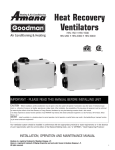
PHRV(R) Series
Heat Recovery Ventilator
PHRV 140
PHRV 150
PHRV 200
PHRVR 155
PHRVR 160
PHRVR 205
PHRVR 210
PHRVR 305
IMPORTANT - P
LEASE READ THIS MANUAL
BEFORE INSTALLING UNIT
CAUTION -
Before installation, careful consideration must be given to how this system
will operate if connected to any other piece of mechanical equipment, i.e. a forced air furnace
or air handler, operating at a higher static. After installation, the compatibility of the two pieces of equipment must be confirmed by measuring the airflow’s of the Heat Recovery
Ventilators by using the balancing procedure found in this manual.
It is always important to assess how the operation of any HRV may interact with vented combustion equipment (i.e. Gas Furnaces, Oil Furnaces, Wood Stoves, etc.).
NEVER - install a ventilator in a situation where its normal operation, lack of operation or partial failure may result in the backdrafting or improper functioning of vented combustion equipment!!!
INSTALLATION, OPERATION AND MAINTENANCE MANUAL
The Best
Limited Warranty
in the Business
• The heat recovery polypropylene core has
a limited lifetime warranty.
• The motors found in all Powrmatic HRV’s
require no lubrication, and are factory
balanced to prevent vibration and promote
silent operation.
• The limited warranty covers normal use.
It does not apply to any defects,
malfunctions or failures as a result of
improper installation, abuse, mishandling,
misapplication, fortuitous occurrence or
any other circumstances outside
Powrmatic’s control.
• Inappropriate installation or
maintenance may result in the
cancellation of the warranty.
• Any unauthorized work will result in
the cancellation of the warranty.
• Powrmatic is not responsible for any
incidental or consequential damages
incurred in the use of the ventilation system.
• Powrmatic is not responsible for providing
an authorized service centre near the
purchaser or in the general area.
• Powrmatic reserves the right to supply
refurbished parts as replacements.
• Transportation, removal and installation
fees are the responsibility of the purchaser.
• The purchaser is responsible to adhering
to all codes in effect in his area.
• The warranty is limited to 5 years on
parts and 7 years on the motor from the
date of purchase, including parts replaced
during this time period. If there is no
proof of purchase available, the date
associated with the serial number will be
used for the beginning of the warranty
period.
* This warranty is the exclusive and only
warranty in effect relative to the ventilation
system and all other warranties either
expressed or implied are invalid.
TABLE OF CONTENTS
TECHNICAL DATA
PHRVR 160 & PHRVR 210..................................................................................3
PHRV 150 & PHRV 200 .................................................................................... 5
PHRVR 305 .................................................................................................... 7
PHRV 140, PHRVR 155 & PHRVR 205............................................................... 9
OPERATION............................................................................................................11
Modes Of Operation .........................................................................................11
Optional Remote Controls................................................................................ 12
Intellitek Multi-Function Controls EDF5................................................................12
INSTALLATION........................................................................................................13
Mounting the Unit .......................................................................................... 13
Location & Ducting.......................................................................................... 14
Examples ....................................................................................................... 17
Air Flow Balancing ......................................................................................... 21
MAINTENANCE ..................................................................................................... 23
TROUBLESHOOTING............................................................................................... 24
ELECTRICAL CONNECTIONS . ............................................................................ ... 25
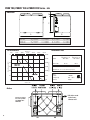
Sizing (Example) for maximum airflow normally required.
HRVs are typically sized to ventilate the whole house at a minimum of 0.35 air changes per
hour. To calculate, simply take the square footage of the house (including basement) and multiply by the height of the ceiling to get cubic volume. Then, divide by 60 and multiply by 0.35.
Example:
SQFT of House
1100
Basement
1100
Total SQFT
2200
Height of ceiling
x 8
Cubic volume
17600
/ 60
Maximum airflow required (CFM)
293
x 0.35
103
* Always consult your local code for sizing requirements in your area.
Alternate Method
Room classification
Number of rooms
Master bedroom
***Illustrations &
images in this
manual may not be
exactly like unit
purchase, these
illustrations & images are for examples
only.***
2
1 cfm = 0.47189 l/s
1 l/s = 3.6 m3/hr
Basement
yes or
CFM (L/s)
CFM Required
x 20 cfm (10 l/s)
=
if yes add 20 cfm / 10 l/s
no
if no = 0
=
Bedrooms
x 10 cfm (5 l/s)
=
Living room
x 10 cfm (5 l/s)
=
Others
x 10 cfm (5 l/s)
=
Kitchen
x 10 cfm (5 l/s)
=
Bathroom
x 10 cfm (5 l/s)
=
Laundry room
x 10 cfm (5 l/s)
=
Utility room
x 10 cfm (5 l/s)
=
Total Ventilation Requirements (add last column )
=
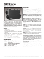
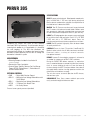
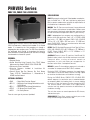
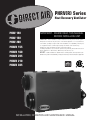
PHRVR Series
PHRVR 160 & PHRVR 210
SPECIFICATIONS
CASE 22 gauge galvanized steel on the PHRV 210 & 24
gauge galvanized steel on the PHRVR 160. Baked powder
coated paint, grey. Insulated with 1" (25 mm) high density
polystyrene foam to prevent condensation and meet the
requirements of the Underwriters Laboratories 94HB.
MOTORS Two (2) German-manufactured, factory-balanced
ebm™ motors with backward curved blades. Motors come
with permanently lubricated sealed bearings guarantee long
life and maintenance-free operation. Seven (7) year warranty.
Introducing the NEW PHRVR series of Heat Recovery
Ventilators (HRV) by Powrmatic. Incoming fresh outdoor air
is filtered before it is heated by the stale outgoing air
through a polypropylene heat recovery core. The HRV then
distributes the preheated fresh filtered air throughout the
home by direct ductwork installed specifically for the HRV or
through the ductwork of a forced-air system.
FEATURES:
• Compact Design
• Electrostatic Filters (washable)
• Airflow Balancing Using Powrmatic's Easy "TRUE" Motor
Adjustment
• External Screw Type Dry Contacts For Push Button
Timers (RTS 2), Dehumidistat 1, Dehumidistat 2
& 5MR Intellitek control.
• Easy Core Guide Channels For Removing Core
• Better Packaging For More Protection In Shipping
OPTIONAL CONTROLS
• 5MR – Digital Multi-Function Control
• DEH. 2 – Mechanical Low Voltage Dehumidistat with
On/Off Switch
• DEH. 1 – Mechanical Low Voltage Dehumidistat
• RTS 2– 15 Minute Push Button Timer
• AQS 1 – Air Quality Sensor
External screw type dry contacts (provided)
CORE A polypropylene heat recovery core configured for an
efficient cross-flow ventilation. Core is 9" x 9" (229 x 229
mm) with a 15" (380 mm) depth {PHRVR 160} or 12" x 12"
(305 x 305 mm) with a 15" (380 mm) depth {PHRVR 210}.
Cores are manufactured to withstand extreme temperature
variations.
FILTERS Two (2) Washable Electrostatic Panel Type Air Filters,
PHRVR 160 is 8.5" (216mm) x 15" (380mm) x 0.125"
(3mm), PHRVR 210 is 11.75" (298mm) x 15" (380mm) x
0.125" (3mm).
CONTROLS External three (3) position (Low/Stand By/
Medium) rocker switch that will offer continuous ventilation.
Powrmatic offers a variety of external controls.
(see optional controls)
DEFROST A preset 5 minute defrost sequence is activated at
an outdoor air temperature of 23ÞF (-5ÞC) and lower.
During the defrost sequence, its mechanism uses a
motorized damper to temporarily block the incoming fresh
air stream allowing the warm air from the home to circulate
through the HRV. The exhaust blower shuts down & the
supply blower switches into high speed to maximize the
effectiveness of the defrost strategy.
The unit then returns to normal operation for 25 minutes,
and continues cycle.
SERVICEABILITY Core, filters, motors and drain pan can be
easily serviced through latched access door. Core
conveniently slides out with ease on an improved railing
system. Electrical box, placed on the outside of the unit,
can also be easily accessed.
Powrmatic, reserves the right to modify, at any time and without notice, any or all of its products’ features, designs, components and specifications to maintain their technological leadership position.
3
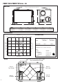
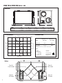
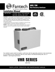
PHRVR 160 & PHRVR 210 Series HRV
Dimensions
TH
5 port for recirculation defrost type models only
E
6"
A
B
C
D
Model
PHRVR 160
A
B
C
D
E
2 1/4" (56mm)
23 1/2" (596mm)
2 5/8" (67mm)
17 3/8" (441mm)
17 3/8" (441mm)
PHRVR 210
2 1/4" (56mm)
27 7/8" (707mm)
2 5/8" (67mm)
17 3/8" (441mm)
20 1/2" (520mm)
Fan Performance
0
19
38
Performance Data
76
94
114
300
Static Pressure (in WC)
1
250
SHR(D) 210
2005R
PHRVR
0.8
0.6
150
0.4
100
SHR(D)
PHRVR1505R
160
0.2
0
0
40
80
120
Airflow (cfm)
Apparent Sensible Apparent Sensible
Effectiveness at
Effectiveness at
Model
32ºF (0ºC)
-13ºF (-25ºC)
PHRVR 160
72 %
69 %
PHRVR 210
71 %
76 %
AIRFLOW CAP. cfm (L/s) @ 0.4 on High Speed
Power
• Volts
• Amperage
50
160
200
0
240
PHRVR 160
PHRVR 210
• Phase
120 VAC
1.5 Amps Total
1.9 Amps Total
Single Phase
5 port for recirculation defrost models
only can be ducted or left open
TH
Airflow
4
200
Static Pressure (Pa)
1.2
Airflow (L/s)
57
Fresh Air
From Outside
Stale Air
From Inside
Stale Air
To Outside
Fresh Air
To Inside
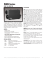
PHRV Series
PHRV 150 & PHRV 200
SPECIFICATIONS
CASE 22 gauge galvanized steel on the PHRV 200 & 24
gauge galvanized steel on the PHRV 150. Baked powder
coated paint, grey. Insulated with 1" (25 mm) high density
polystyrene foam to prevent condensation and meet the
requirements of the Underwriters Laboratories 94HB.
MOTORS Two (2) German-manufactured, factory-balanced
ebm™ motors with backward curved blades. Motors come
with permanently lubricated sealed bearings guarantee long
life and maintenance-free operation. Seven (7) year warranty.
Introducing the NEW PHRV series of Heat Recovery
Ventilators (HRV) by Powrmatic. Incoming fresh outdoor air
is filtered before it is heated by the stale outgoing air
through a polypropylene heat recovery core. The HRV then
distributes the preheated fresh filtered air throughout the
home by direct ductwork installed specifically for the HRV or
through the ductwork of a forced-air system.
FEATURES:
• Compact Design
• Electrostatic Filters (washable)
• Balancing Dampers Included In Installation Kit
(not factory installed)
• E xternal Screw Type Dry Contacts For Push Button
Timers (RTS 2), Dehumidistats 1, Dehumidistat 2
& 5MR Intellitek control.
• Easy Core Guide Channels For Removing Core
• Better Packaging For More Protection In Shipping
OPTIONAL CONTROLS
• 5MR – Digital Multi-Function Control
• DEH. 2 – Mechanical Low Voltage Dehumidistat with
On/Off Switch
• DEH. 1 – Mechanical Low Voltage Dehumidistat
• RTS 2– 15 Minute Push Button Timer
• AQS 1 – Air Quality Sensor
CORE A polypropylene heat recovery core configured for an
efficient cross-flow ventilation. Core is 9" x 9" (229 x 229 mm)
with a 15" (380 mm) depth (PHRV 150) or 12" x 12" (305 x
305 mm) with a 15" (380 mm) depth (PHRV 200). Cores are
manufactured to withstand extreme temperature variations.
FILTERS Two (2) Washable Electrostatic Panel Type Air Filters,
PHRV 150 is 8.5" (216mm) x 15" (380mm) x 0.125"
(3mm), PHRV 200 is 11.75" (298mm) x 15" (380mm) x
0.125" (3mm).
CONTROLS External three (3) position (Low/Stand By/
Medium) rocker switch that will offer continuous ventilation.
Powrmatic offers a variety of external controls. (see optional
controls)
DEFROST A preset 5 minute defrost sequence is activated at
an outdoor air temperature of 23ÞF (-5ÞC) and lower.
During the defrost sequence, the supply blower shuts down
& the exhaust blower switches into high speed to maximize
the effectiveness of the defrost strategy.
The unit then returns to normal operation for 25 minutes,
and continues cycle.
SERVICEABILITY Core, filters, motors and drain pan can be
easily serviced through latched access door. Core
conveniently slides out with ease on an improved railing
system. Electrical box, placed on the outside of the unit, can
also be easily accessed.
External screw type dry contacts (provided)
Powrmatic, reserves the right to modify, at any time and without notice, any or all of its products’ features, designs, components and specifications to maintain their technological leadership position.
5
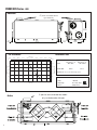
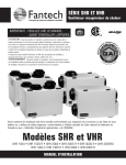
PHRV 150 & PHRV 200 Series HRV
Dimensions
E
6"
A
B
A
B
C
D
E
2 1/4" (56mm)
23 1/2" (596mm)
2 5/8" (67mm)
17 3/8" (441mm)
16 1/8" (413mm)
PHRV 200
2 1/4" (56mm)
27 7/8" (707mm)
2 5/8" (67mm)
17 3/8" (441mm)
20 1/2" (520mm)
19
38
Performance Data
Airflow (L/s)
57
76
94
Static Pressure (in WC)
1
114
300
250
PHRV2004
200
SHR
0.8
200
0.6
150
0.4
100
0.2
50
SHR 1504
PHRV
150
0
0
40
80
120
Airflow (cfm)
160
200
0
240
Static Pressure (Pa)
1.2
D
Model
PHRV 150
Fan Performance
0
C
Apparent Sensible Apparent Sensible
Effectiveness at
Effectiveness at
Model
32ºF (0ºC)
-13ºF (-25ºC)
PHRV 150
72 %
69 %
PHRV 200
71 %
76%
AIRFLOW CAP. cfm (L/s) @ 0.4 on High Speed
Power
• Volts
• Amperage
PHRV 150
PHRV 200
• Phase
120 VAC
1.5 Amps Total
1.9 Amps Total
Single Phase
Airflow
6
Fresh Air
From Outside
Stale Air
From Inside
Stale Air
To Outside
Fresh Air
To Inside
PHRVR 305
SPECIFICATIONS
CASE 22 gauge galvanized steel. Baked powder coated paint,
grey. Insulated with 1" (25 mm) high density polystyrene
foam to prevent condensation and meet the requirements of
the Underwriters Laboratories 94HB.
MOTORS Two (2) German-manufactured, factory-balanced
ebm™ motors with backward curved blades. Motors come
with permanently lubricated sealed bearings guarantee long
life and maintenance-free operation. Seven (7) year warranty.
CORES Two (2) polypropylene heat recovery cores configured
for an efficient cross-flow ventilation. Core is 12" x 12" (305
x 305 mm) with a 15" (380 mm) depth. Cores are
manufactured to withstand extreme temperature variations.
Introducing the PHRVR 305 series of Heat Recovery
Ventilators (HRV) by Powrmatic. As with previous designs,
incoming fresh outdoor air is filtered before it is heated by
the stale outgoing air. The HRV then distributes the
preheated fresh filtered air throughout the home by direct
ductwork installed specifically for the HRV or through the
ductwork of a forced-air system.
FILTERS Two (2) synthetic high quality filters for better indoor
air quality and clean air.
NEW FEATURES:
DEFROST A preset 5 minute defrost sequence is activated at
an outdoor air temperature of 23ÞF (-5ÞC) and lower.
• Balancing Dampers Included In Installation Kit
(not factory installed)
• Electrostatic Filters (washable)
• External Screw Type Dry Contacts For Push Button
Timers (RTS 2), Dehumidistats 1, Dehumidistat 2
& 5MR Intellitek control
OPTIONAL CONTROLS
• 5MR – Digital Multi-Function Control
• DEH. 2 – Mechanical Low Voltage Dehumidistat with
On/Off Switch
• DEH. 1 – Mechanical Low Voltage Dehumidistat
• RTS 2– 15 Minute Push Button Timer
• AQS 1 – Air Quality Sensor
CONTROLS External three (3) position (Low/Stand By/
Medium) rocker switch that will offer continuous ventilation.
Powrmatic offers a variety of external controls.
(see optional controls)
During the PHRVR 305 defrost sequence, its mechanism
uses a motorized damper to temporarily block the incoming
fresh air stream allowing the warm air from the home to
circulate through the HRV. The exhaust blower shuts down &
the supply blower switches into high speed to maximize the
effectiveness of the defrost strategy.
The unit then returns to normal operation for 25 minutes,
and continues cycle.
SERVICEABILITY Core, filters, motors and drain pan can be
easily serviced through latched access door.
External screw type dry contacts (provided)
Powrmatic, reserves the right to modify, at any time and without notice, any or all of its products’ features, designs, components and specifications to maintain their technological leadership position.
7
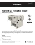
PHRVR 305 Series HRV
Dimensions
TH
5 port for recirculation defrost
type models only
22.20"
564mm
6"
2.20"
56mm
2.20"
56mm
50.87"
1292mm
Fan Performance
19.00
38.00
Performance Data
57.00
Airflow (L/s)
76.00
94.00
114.00
123.00
142.00
Static Pressure (in WC)
1
250.00
0.8
200.00
PHRVR 305
SHR3005R
0.6
150.00
0.4
100.00
0.2
50.00
0
0.00
Airflow
8
162.00
300.00
40.00
80.00
120.00
200.00
160.00
Airflow (cfm)
240.00
280.00
320.00
0.00
360.00
Static Pressure (Pa)
0.00
1.2
17.36"
441mm
Apparent Sensible Apparent Sensible
Effectiveness at
Effectiveness at
Model
32ºF (0ºC)
-13ºF (-25ºC)
PHRVR 305
92 %
91 %
AIRFLOW CAP. cfm (L/s) @ 0.4 on High Speed
Power
• Volts
• Amperage
• Phase
5 port for recirculation defrost models
only, can be ducted or left open
TH
120 VAC
2.7 Amps Total
Single Phase
PHRV(R) Series
PHRV 140, PHRVR 155 & PHRVR 205
SPECIFICATIONS
CASE 22 gauge galvanized steel. Baked powder coated paint,
grey. Insulated with 1" (25 mm) high density polystyrene
foam to prevent condensation and meet the requirements of
the Underwriters Laboratories 94HB.
MOTORS Two (2) German-manufactured, factory-balanced
ebm™ motors with backward curved blades. Motors come
with permanently lubricated sealed bearings guarantee long
life and maintenance-free operation. Seven (7) year warranty.
Introducing the PHRV(R) series of Heat Recovery Ventilators
(HRV) by Powrmatic. Incoming fresh outdoor air is filtered
before it is heated by the stale outgoing air through a
polypropylene heat recovery core. The HRV then distributes
the preheated fresh filtered air throughout the home by
direct ductwork installed specifically for the HRV or through
the ductwork of a forced-air system.
FEATURES:
• Compact Design
• Airflow Balancing Using Fantech's Easy "TRUE" Motor
Adjustment for models PHRVR 155 & PHRVR 205
• Electrostatic Filters (washable)
• Balancing Dampers Included In Installation Kit
(not factory installed)
• E xternal Screw Type Dry Contacts For Push Button
Timers (RTS 2), Dehumidistats 1, Dehumidistat 2
& 5MR Intellitek control.
OPTIONAL CONTROLS
• 5MR – Digital Multi-Function Control
• DEH. 2 – Mechanical Low Voltage Dehumidistat with
On/Off Switch
• DEH. 1 – Mechanical Low Voltage Dehumidistat
• RTS 2– 15 Minute Push Button Timer
• AQS 1 – Air Quality Sensor
External screw type dry contacts (provided)
CORE A polypropylene heat recovery core configured for an
efficient cross-flow ventilation. Core is 9" x 9" (229 x 229
mm) with a 15" (380 mm) depth (PHRV 140 & PHRVR
155) or 12" x 12" (305 x 305 mm) with a 15" (380 mm)
depth (PHRVR 205). Cores are manufactured to withstand
extreme temperature variations.
FILTERS Two (2) Washable Electrostatic Panel Type Air Filters,
PHRV 140 & PHRVR 155 is 8.5" (216mm) x 15" (380mm) x
0.125" (3mm), PHRVR 205 is 11.75" (298mm) x 15"
(380mm) x 0.125" (3mm).
CONTROLS External three (3) position (Low/Stand By/
Medium) rocker switch that will offer continuous ventilation.
Powrmatic offers a variety of external controls to
compliment its units and allows you to appreciate its
functions to the fullest. (see optional controls)
DEFROST A preset 5 minute defrost sequence is activated at
an outdoor air temperature of 23ÞF (-5ÞC) and lower.
During the PHRV 140 defrost sequence, the supply blower
shuts down & the exhaust blower switches into high speed
to maximize the effectiveness of the defrost strategy.
During the PHRVR Series (PHRVR 155 & PHRVR 205)
defrost sequence, its mechanism uses a motorized damper
to temporarily block the incoming fresh air stream allowing
the warm air from the home to circulate through the HRV.
The exhaust blower shuts down & the supply blower
switches into high speed to maximize the effectiveness of
the defrost strategy.
The unit then returns to normal operation for 25 minutes,
and continues cycle.
SERVICEABILITY Core, filters, motors and drain pan can be
easily serviced through latched access door.
Powrmatic, reserves the right to modify, at any time and without notice, any or all of its products’ features, designs, components and specifications to maintain their technological leadership position.
9
PHRV 140, PHRVR 155 & PHRVR 205 Series HRV
Dimensions
D
C
A
Model
PHRV 140
PHRVR 155
PHRVR 205
Fan Performance
19.00
38.00
A
B
C
D
23 3/4" (604mm)
23 3/4" (604mm)
28" (711mm)
17 1/4" (438mm)
17 1/4" (438mm)
17 1/4" (438mm)
16 1/4" (413mm)
16 1/4" (413mm)
20 1/2" (521mm)
2 1/4" (56mm)
2 1/4" (56mm)
2 1/4" (56mm)
Performance Data
76.00
94.00
Static Pressure (in WC)
1
250.00
0.8
0.6
200.00
PHRV VHR1404/
140 &
PHRVRVHR1405R
155
150.00
0.4
100.00
PHRVR
205
VHR2004
0.2
0
0.00
114.00
300.00
VHR2005R
40.00
80.00
120.00
160.00
Airflow (cfm)
200.00
50.00
0.00
240.00
Static Pressure (Pa)
0.00
1.2
Airflow (L/s)
57.00
B
Apparent Sensible Apparent Sensible
Effectiveness at
Effectiveness at
Model
32ºF (0ºC)
-13ºF (-25ºC)
PHRV 140
81 %
79 %
PHRVR 155
81 %
79 %
PHRVR 205
71 %
76 %
AIRFLOW CAP. cfm (L/s) @ 0.4 on High Speed
Power
• Volts
• Amperage
• Phase
120VAC
0.8 - 1.6 A
Single
Airflow
Optional recirculation
Optional recirculation
duct collar (provided)
duct collar (provided)
with PHRVR 155 &
PHRVRwith
205VHR 1405R
& VHR 2005R only
10
* All collars on the
Series have a
diameter of 6".
OPERATION
A Heat Recovery Ventilator (HRV) is designed to bring fresh air into a building while exhausting an equal amount of stale air. During the winter months,
the incoming cold fresh air is warmed by utilizing the heat recovered from the stale air before it is exhausted to the outdoors. During summer months
when the indoor space is air conditioned, the HRV will help in cooling the incoming fresh air with the stale air that is being exhausted.
Powrmatic HRV’s are designed to run continuous or on intermittent, giving the homeowner complete control over their air quality. Continuous low
speed ventilation is recommended, which will help eliminate carbon dioxide, voc’s and other gases as well as freshen up the home. Intermittent high
speed ventilation can be obtained through a variety of optional remote controls found in this manual. Below are some examples of seasonal operation
of an HRV.
Winter:
Humidity control is very important during the winter months.
This is when problems will be most apparent since condensation on the windows will often occur. The colder the outside
temperature, the greater the risk of condensation in the
home. The average relative humidity should be maintained
between (30-60) to avoid condensation. Low speed continuous ventilation with high speed override is recommended.
Spring:
Temperatures are more moderate and become
warmer each day. To keep the humidity and temperature uniform, set the dehumidistat higher (if
installed). You may also switch the HRV to standby
mode if desired.
Summer:
The air is sometimes hot and humid. To stop the warm
humid air from entering, set the dehumidistat at its highest level. If the Intellitek series controller is installed, the
air exchanger can be set to cycle the unit on and off as
desired from that wall control. However, continuous ventilation is recommended.
Fall:
Rain and rapid temperature changes make it difficult
to control the internal humidity level and may result
in condensation on the windows. A remote dehumidistat may help give greater control over the
inside environment.
MODES OF OPERATION
The entire line of PHRV & PHRVR series Heat Recovery Ventilators comes equipped with Powrmatic's new electronic uni-control board which offers
a wide variety of features making it the ultimate ventilation control system. Powrmatic engineers have used the latest technology to provide solid,
trouble free operation under any conditions.
The Powrmatic uni-control board offers stand alone operating capabilities as well as an exclusive 2 wire communication to most external controls.
The trouble-free optional controls include: two different rotary dial dehumidistats, an air quality sensor (3 wire communication required), a 15 minute
remote push-button timer, as well as the most sophisticated line of remote wall mounted controls, the Intellitek 5MR.
An on-board diagnostic LED helps find problems quickly and efficiently. For example the LED can be used to signal a broken or shorted electronic
wall control wire. Electronic air temperature probe gives this board accurate readings in order to minimize unnecessary defrost operation, and the
on-board jumpers provide the user with the option of adjusting defrost time and sequence to optimize performance under abnormal conditions. The
defrost operation is automatic and is usually never adjusted.
1. Continuous / Ventilation Mode
In this mode of operation both fans
are operating and exchanging air with
Air to the outside. The heat recovery ventilaAir to
House
Outside
tor (HRV) constantly exchanges the
air at the rate you select, either at low
or medium speed, and switches to high speed when activated by an
optional remote control. The "Low" and "Med" fan speed selection will cause
the unit to operate in continuous exchange mode at an exchange rate of
35% and 50% maximum airflow rating respectively. Continuous mode is
recommended, since pollutants are slowly but constantly being generated
in your house.
Air from
Outside
Air from
House
Air from
House
3.Defrost/Recirculation
(PHRVR Models)
Mode
The automatic defrost cycle PHRVR models of HRV consists of a damper defrost
Air to
House which allows air to recirculate throughout
the unit & home. When the supply air
stream temperature goes below -5°C (23°F), the exhaust motor shuts down,
the supply motor goes to high speed, and a damper closes the supply, opening
a 5th collar. The ambient air is then recirculated through the unit & home for a
period of 5 minutes. The unit will then resume normal operation for a time
period of 25 minutes. This damper defrost cycle continues until the supply air
stream rises above 0°C (32°F). The recirculation feature can be obtained with
the use of an optional Intellitek EDF5 (5MR) control.
2. Intermittent / Standby Mode
The system is always on standby and operates
at high speed when activated by an optional
remote control. "Standby" should be selected if
the user wishes to stop the unit from continuous
exchange. We recommend that the "Standby"
mode only be used if your system is equipped with an optional external
control, in which case, the unit would activate to "High" fan speed, until
the control is satisfied and then return to standby (off).
* no exchange of air
4. Defrost (PHRV Models)
The automatic defrost cycle PHRV
models of HRVs consists of a fan
Air to
shutdown. When the supply air
outside
stream temperature goes below
-5°C (23°F), the supply motor
shuts down and the exhaust motor goes into high speed. Ambient air
is passed through the unit for a period of 5 minutes. The supply motor
will then re-start and run at the preset speed. The exhaust motor will
also slow down to the preset speed, and the unit will operate in the run
cycle for 25 minutes. This fan shutdown defrost cycle continues until
the supply air stream rises above 0°C (32°F).
Air from
House
11
OPERATION (CONT'D)
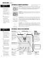
OPTIONAL REMOTE CONTROLS
PRACTICAL
TIPS
To avoid window condensation:
• It is not necessary to
change the humidity control
every day. Monitor the
average weekly
temperature or experiment
with various settings until
you find a level that is
comfortable for you. Adjust
the control when needed.
NOTE:
A dehumidistat is ideal for
use in energy efficient
houses where indoor
humidity (during the
heating season) is higher
than outdoor levels. High
humidity is a major cause
of structure damage and
IAQ problems such as mold
and mildew.
Dehumidistat I - The wall mount dehumidistat monitors the humidity level in the
area it is installed. When the humidity level rises above the desired set-point,
the HRV will activate to high speed/override mode. Once the humidity level
returns to desired condition, the unit will return to the normal mode.
2 wire installation
Dehumidistat II - The wall mount dehumidistat II offers the same features of the
dehumidistat I plus additional off/on control for the HRV. Dial illuminates when
in override mode.
4 wire installation
Air Quality Sensor - The wall mount Air Quality Sensor (AQS) monitors indoor
air quality and activates the override mode when carbon monoxide, formaldehyde,
benzene, volatile organic compounds and other pollutants are detected. The
unit will then return to normal mode once the air pollutants are reduced to a
pre-determined lower level.
3 wire installation
2 wire installation
PRACTICAL
TIPS
NOTE:
When an Intellitek control
is installed, the rocker
switch located on the right
hand side of the HRV will
be automatically
deactivated giving the user
complete control from
wherever he/she wishes to
mount the control pad.
NOTE:
The override speed cannot
be set at a fan speed lower
or equal to the normal
operating fan speed. For
example, if the unit is
normally operating at a
medium fan speed, the
override fan speed will be
automatically set to high.
NOTE:
5MR model, changing the
override speed will change
default override speed for
other external controls.
EXAMPLES:
If on the 5MR control, you
have set the override
control at medium, and
you start an external
remote control (15 min.
timer), the unit will run at
medium speed for 15 min.
12
*A
ll controls are low voltage. 18 to 24
gauge wire is recommended.
* This control is not a warning device.
15-min Timer - The 15-minute remote timer is typically installed in areas where
contaminated such as moisture and odors, are produced. Simply push the
button and the HRV will activate to high speed for 15 minutes. Up to 5
electronic timers can be installed throughout the building at a distance of up to
500 feet (152 meters) from the HRV.
OPTIONAL INTELLITEK CONTROL
DIGITAL DISPLAY
Shows Indoor Humidity Level
This control will not read
below 29% RH
5MR
DEHUMIDISTAT CONTROL
(see description on top of this page)
INTELLITEK
MULTI-FUNCTION
WALL CONTROL
4 1/2"
(114 mm)
OVERRIDE TIMER
When pressed, unit will provide high
speed ventilation
for one 15, 30 or 60 minute
period.
Control multiple functions of your
Powrmatic HRV with
one slimline wall control. Two wire connection simplifies installation. Use one EDF5 per
PHRVR installed.
5 1/8"
(130 mm)
MAINTENANCE LIGHT
Light comes on when
it’s time to clean unit.
Width = 4 1/2" (110mm)
Height = 5 1/8" (130mm)
Thickness = 5/8" (15mm)
POWER
On/Off and Reset
MODES
Select Intermittent,
Recirculation or
Continuous
Ventilation Modes
MODE SPEED
Set Unit to Low,
Medium or High
Speed
CYCLE CONTROL
Set unit to cycle on
15, 20, or 30 minutes every hour
OVERRIDE SPEED
CONTROL
Push to select
override speed of
unit.
INSTALLATION
PRACTICAL TIPS
•Install the unit close to the outside wall on which the supply and exhaust hoods will be mounted.
•Have a nearby power supply 120 Volts, 60Hz.
•Have the possibility of mounting the unit to supporting beams.
•Mount the unit as
level as possible in order to allow proper condensate drainage.
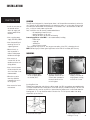
LOCATION
The HRV must be located in a heated space where it will be possible to conveniently service the
unit. Typically the HRV would be located in the mechanical room or an area close to the outside
wall where the weatherhoods will be mounted. If a basement area is not convenient or does not
exist, a utility or laundry room may be used.
Attic installations are not normally recommended due to:
- the complexity of work to install
- freezing conditions in the attic
- difficulty of access for service and cleaning
Connecting appliances to the HRV It is not recommended, including:
- clothes dryer
- range top
- stovetop fan
- central vacuum system
These appliance may cause lint, dust or grease to collect in the HRV , damaging the unit.
NOTE: Connecting any of these type of appliances to the HRV will invalidate your warranty
MOUNTING
•Have access to
a water drain for the condensate of the unit
during defrost.
•Have a certain amount of heat around the unit (attic installation is not recommended).
•Minimize any noise level that would be
created by the unit in the living area.
•Have access for future maintenance.
1 Place Fastening hooks
on the strapping board
or the floor joists.
2 Attach a hanging chain
(provided) to each 10 3/4”
(19 mm) bolt (provided) in
the top 4 corners of the
unit and tighten.
3 Hang the unit by
slipping a link onto the
hanging hooks, making
sure the unit is level.
Installing Drain Line
Through normal operation and during its defrost mode, the HRV may produce some condensation.
This water should flow into a nearby drain, or be taken away by a condensate pump. The HRV and
all condensate lines must be installed in a space where the temperature is maintained above the
freezing point. A “P” trap should be made in the drain line. This will prevent odors from being
drawn back up into the unit.
1 Install the drain nipple.
2 Install the drain hose, making a “P” trap
13
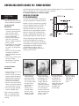
INSTALLING DUCTS GOING TO / FROM OUTSIDE
A well designed and installed ducting system will allow the HRV to operate at its maximum efficiency.
Always try to keep duct runs as short and straight as possible.
See Installation Diagrams for installation examples.
PRACTICAL
TIPS
•Decide where your intake and exhaust hoods will be located.
Locating the Intake
Weatherhood
•S
hould be located upstream
(if there are prevailing winds)
from the exhaust outlet
• At least 6’ (2m) from the exhaust weatherhood
• At least 6’ (2m) away from
dryer vents and furnace
exhaust ( medium or high efficiency furnaces)
• A minimum of at least 6’ (2m)
from driveways, oil fill pipes,
gas meters, or garbage containers
• At least 18” (457mm) above the ground, or above the
depth of expected snow accumulation
• At least 3’ (1m) from the corner of the building
• Do not locate in a garage,
attic or crawl space
INSTALLING THE DUCTING
TO THE WEATHERHOODS
The inner liner of the flexible insulated duct
must be clamped to the sleeve of the weatherhoods (as close to the outside as possible)
and to the appropriate port on the HRV. The
insulation should remain full and not be
squished. The outer liner, which acts as a
vapor barrier must be completely sealed to
outer wall and the HRV using tape and or
caulking. A good bead of high quality caulking (preferably acoustical sealant) will seal
the inner flexible duct to both the HRV port
and the weatherhood prior to clamping.
To minimize air flow restriction, the flexible
insulated duct that connects the two outside
weatherhoods to the HRV should be
stretched tightly and be as short as
possible. Twisting of folding the duct will
severely restrict air flow.
Locating the Exhaust
Weatherhood
•A
t least 6’ (2m) from the ventilation air intake
• At least 18” (457mm) above ground or above the depth of expected snow accumulation
• At least 3’ (1m) away from
the corner of the building
• Not near a gas meter, electric
meter or a walkway where fog
or ice could create a hazard
• Not into a garage, workshop
or other unheated space
When installing the weatherhood, it’s outside perimeter
must be sealed with exterior
caulking.
14
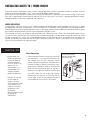
1 Using the collar of
the outside hood,
outline the intake &
exhaust holes to be
cut. The holes should
be slightly larger
than the collar to
allow for the
thickness of the
insulated flexible
duct. Cut a hole
for both the intake
and exhaust hoods.
2 Pull the insulated
flexible duct through
the opening until it is
well extended and
straight. Slide the
duct’s inner vinyl
sleeve over the hood
collar and secure, pull
the insulation over
the duct and then the
vapor barrier over the
sleeve and secure
with duct tape.
3 Push the hood into
4 Using a caulking
the opening. Attach
gun, seal around
the hood to the
both hoods to
outside wall with
prevent any
mounting screws.
leaks.
Repeat the installation
procedure for both
the Supply and
Exhaust hood.
INSTALLING DUCTS TO / FROM INSIDE
To maximize airflow in the ductwork system, all ducts should be kept short and have as few bends or elbows as possible. Forty-five
degree are preferred to 90º elbows. Use “Y” tees instead of 90º elbows whenever possible.
All duct joints must be fastened with screws or duct sealant and wrapped with a quality duct tape to prevent leakage. Aluminum foil
duct tape is recommended. Galvanized ducting from the HRV to the living areas in the house is recommended whenever possible,
although flexible duct can be used in moderation when necessary.
SUPPLY AIR DUCTING
In homes without a forced air furnace, fresh air should be supplied to all habitable rooms including, bedrooms and living areas. It should
be supplied from high wall or ceiling locations. Grilles that diffuse the air comfortably such as Powrmatic grille are recommended.To
avoid possible noise transfer through the ductwork system, a short length (approximately 12”, 300 mm) of nonmetallic flexible insulated
duct should be connected between the HRV and the supply/exhaust ductwork system.
The main supply and return lines to/from the HRV must be 6 inches (150 mm) minimum. Branch lines to the individual rooms may be
as small as 4 inches (100 mm), but 5 inch (125 mm) lines are preferred.If the floor is the only option available, then special care should
be taken in locating grilles. Areas such as under baseboard heaters will help to temper the air. Also optional inline duct heaters are
available for mounting in the supply duct work to add heat if required.In homes with a forced air furnace, you may want to connect the
HRV to the furnace ductwork (see information below).
PRACTICAL TIPS
Direct Connection
•Building Codes and Combustion Appliance Installation Codes do not allow location of return air grilles or any opening such as a “breathing tee” in an enclosed room with spillage susceptible combustion appliances.
•The fresh air inlet from
the HRV needs to respect a minimum distance from the furnace return drop to ensure proper air mixing and
temperature at the furnace core.
See furnace manufacturer for appropriate specifications.
• A direct connection requires that the fan of the furnace
runs continuously. It may be inter-linked electrically
(low voltage) with the HRV (Accessory Control
Contacts) for intermittent demand. Should you wish to
hard duct the supply air directly into the cold air return
of the furnace, remember to check the airflow balance
of the HRV with the furnace fan both “on” and “off” to
determine that it does not imbalance the HRV more
than 10%. Make sure you respect the minimum
distance from the supply air in of the HRV and the
furnace (Refer to your local and National Building &
Heating Codes for any variations in these notes).
For minimum distance
See local building codes
and practical tips.
from HRV
15
INSTALLING DUCTS TO / FROM INSIDE (CONT'D)
Exhaust Air Ducting
The stale air exhaust system is used to draw air from the points in the house where the worst air quality problems occur. It is recommended that return air ducts be installed in the bathroom, kitchen, and laundry room. Additional return air ducts from strategic
locations (i.e. greenhouse, atrium, swimming pool, sauna, etc.) may be installed. The furnace return duct may be also used to exhaust
from. In this method, the exhaust air is not ducted back from bathrooms, kitchens, etc to the HRV with “dedicated lines”.
This method has become popular and provides good ventilation when installed in accordance with the instructions. The furnace
blower must be running when the HRV is operating for this method to be effective.
Dedicated Installation for Existing Home -
PRACTICAL TIPS
• For new construction, the rigid ducts are run in the walls.
• Choose the location for
your Supply and Exhaust
grilles. The Supply
grilles should be located
in every habitable room and the Exhaust Grilles
should be located in the
wet rooms.
• A piece of flexible
ducting should be
placed between the
Supply Air In and Out
collar of the HRV and
the rigid ducting to
absorb any noise or
vibrations.
(non forced air heating / cooling system)
1 Begin with the duct collar marked “Exhaust Air In”. Slide a short piece
(12”) of flexible duct over the duct collar. Using duct tape, tape the flexible
duct to the collar. Run the flexible ducting to the main rigid duct trunk line,
which connects to the remainder of the ducts going to and from rooms in
the house. Repeat the steps for the “Supply Air Out” on the side of the HRV.
2 Working from a closet, attic or inside your joist wall, run the length of
ducting required for the proper grille location and cut a hole in the drywall.
Fasten the mounting collar (optional) to the ducting and fasten the collar
to the wall or ceiling with screws.
3 The grille - airflow can be adjusted by rotating the inside unit. It is
recommended that the grilles be completely opened at first and then
adjusted later as needed.
• For proper network
of ducting, see TYPES OF
INSTALLATIONS.
• The grilles are to be
installed on the ceiling
or on the wall 6” (152
mm) to 12” (305 mm)
from the ceiling.
4 Push the grille into the optional mounting collar or directly into installed elbow.
16
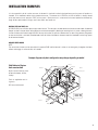
INSTALLATION EXAMPLES
It is the responsibility of the installer to ensure all ductwork is sized and installed as designed to ensure the system will perform as
intended. All air movement devices have a performance curve. The amount of air (CFM) that an HRV will deliver is directly related
to the total external static pressure (E.S.P.) of the system. Static pressure is a measure of resistance imposed on the blower by
length of duct work/number of fittings used in duct work, duct heater etc.
DUCTING FIFTH PORT UNITS (R)
All PHRVR HRV’s have a fifth duct port on top or side of the unit. This duct port is for both defrost and the recirculation mode. A motorized
damper installed in the port closes during defrost or recirculation temporarily blocking the incoming fresh air-stream, allowing the warm
air from the house to circulate through the HRV. You may wish to duct this port to a common clean air room (living room or dining room)
so when recirculation is activated, household odors from the kitchen, bathroom or basement won’t be introduced into the living spaces
of the home environment.
RADIANT HEATED HOMES
NOTE:
The recirculation function can be accessed with a optional 5MR intellitek control. It allows air to move gently throughout the home
without exchanging air to the outside, until needed.
Example diagram only-duct configuration may change depending on model
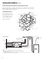
Fully Dedicated System
(new construction)
Exhaust
Bathroom
Bedrooms
Central Control - optional
Fresh air to living room
Stale air drawn from key areas
of home (bathroom, kitchen,
laundry)
Fresh air supplied to main living areas
HRV must be balanced
180
0m
m
HRV
Fresh Air
460 mm
Exhaust Air
17
INSTALLATION EXAMPLES (CONT'D)
Example diagram only-duct configuration may change depending on model
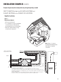
DIRECT CONNECTION of the SUPPLY AIR STREAM to the FURNACE COLD AIR RETURN
(Stale air drawn from key areas of home)
Partially Dedicated System
Exhaust
Central Control - optional
Stale air drawn from key areas of
home (bathroom, kitchen, laundry)
Bathroom
Bedrooms
Return Air
Furnace thermostat
Fresh air supplied to main living
areas via the forced air system.
HRV must be balanced
HRV
Connection
180
0m
m
HRV
Fresh Air
Exhaust Air
* Ducts connection may
vary depending on model
Outdoors
460 mm
Return Air
Exhaust Air from various parts of home.
i.e. bathrooms (if required),
kitchens (if required)
1m
(3’-3”) min.
recommended
Cool Air
Return
* Unit is normally balanced on HIGH speed with furnace blower ON.
NOTES:
1.Furnace blower may be required to operate when HRV is on to provide good air distribution.
2.Weatherhood arrangement is for drawing purposes only. 6’ (2m) minimum separation recommended.
18” (460mm) above grade minimum.
3.Due to the differences in pressure between the HRV and the equipment it is being connected to, the HRV’s airflow must be confirmed
on site, using the balancing procedure found in the installation manual.
18
INSTALLATION EXAMPLES (CONT'D)
Example diagram only-duct configuration may change depending on model
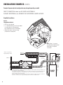
DIRECT CONNECTION of both the HRV SUPPLY AIR STREAM and
EXHAUST AIR STREAM to the FURNACE COLD AIR RETURN
Simplified Installation
Option 1
(Return/Return Method)
• HRV must be balanced
• It is mandatory that the furnace blower
run continuously or HRV operation
be interlocked with the furnace blower
• Check local codes/authority having
jurisdiction for acceptance
Note: Option 1 is the preferred/recommended method
when doing a simplified
installation
* Ducts connection may
vary depending on model
Return Air
40”
Min.
Outdoors
1m
(3’-3”) min.
recommended
NOTES:
Cool Air
Return
1. Furnace blower may be required to operate when ventilation from HRV is required. The furnace should be set to
run continuously or interlocked with HRV.
2. A minimum separation of 39 inches (1m) is recommended between the two direct connections.
3. The exhaust air connection should be upstream of the supply air connection to prevent exhausting any fresh air.
4. Weatherhood arrangement is for drawing purposes only. 6’ (2m) minimum separation recommended. 18” (460
mm) above grade minimum.
5. Due to the differences in pressure between the HRV and the equipment it is being connected to, the HRV’s airflow must be confirmed on site, using the balancing procedure found in the installation manual.
* Unit is
normally
balanced
on HIGH
speed
with
furnace
blower
ON.
19
INSTALLATION EXAMPLES (CONT'D)
Example diagram only-duct configuration may change depending on model
DIRECT CONNECTION of both the HRV SUPPLY AIR STREAM &
EXHAUST AIR STREAM to the FURNACE COLD AIR RETURN & SUPPLY AIR SIDE
Simplified Installation
Option 2
(Supply/Return Method)
• HRV must be balanced
• It is recommended that the furnace blower
run continuously or HRV operation
be interlocked with the furnace blower
• Check local codes /authority having
jurisdiction for acceptance
Note: Option 1 is the preferred/recommended method
when doing a simplified
installation
* Ducts connection may
vary depending on model
Return Air
1m
(3’-3”) min.
Outdoors
recommended
Cool Air
Return
NOTES:
1. Furnace blower may be required to operate when ventilation from HRV is required. The furnace should be set to
run continuously or interlocked with HRV.
2. The exhaust air connection should be upstream of the supply air connection to prevent exhausting any fresh air.
3. Weatherhood arrangement is for drawing purposes only. 6 feet (2m) minimum separation recommended.
18 inches (460 mm) above grade minimum.
4. Due to the differences in pressure between the HRV and the equipment it is being connected to, the HRV’s airflow must be confirmed on site, using the balancing procedure found in the installation manual.
20
1m
(3’-3”) min.
recommended
* Unit is
normally
balanced
on HIGH
speed
with
furnace
blower
ON.
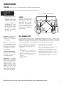
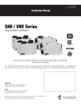
AIR FLOW BALANCING
CAUTION
• If the unit’s airflows are not properly balanced...
- The unit may not operate at it’s maximum efficiency.
- Heat recovery core damage may occur.
- The unit’s use could cause negative or positive pressure in your home causing cold air to enter or other combustible equipment to backdraft.
- The unit may not defrost properly.
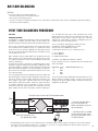
PITOT TUBE BALANCING PROCEDURE
PITOT TUBE
BALANCING PROCEDURE
The following is a method of field balancing an HRV using a Pitot tube,
advantageous in situations when flow stations are not installed in the
ductwork. Procedure should be performed with the HRV on high speed.
The first step is to operate all mechanical systems on high speed, which
have an influence on the ventilation system, i.e. the HRV itself and the
forced air furnace or air handler if applicable. This will provide the maximum pressure that the HRV will need to overcome, and allow for a more
accurate balance of the unit.
Drill a small hole in the duct (about 3/16), three feet downstream of any
elbows or bends, and one foot upstream of any elbows or bends. These
are recommended distances but the actual installation may limit the
amount of straight duct.
The Pitot tube should be connected to a magnehelic gauge or other
manometer capable of reading from 0 to 0.25 in. (0-62 Pa) of water,
preferably to 3 digits of resolution. The tube coming out of the top of the
pitot is connected to the high pressure side of the gauge. The tube coming out of the side of the pitot is connected to the low pressure or reference side of the gauge.
Insert the Pitot tube into the duct; pointing the tip into the airflow. For
general balancing it is sufficient to move the pitot tube around in the duct
and take an average or typical reading. Repeat this procedure in the
other (supply or return) duct. Determine which duct has the highest
airflow (highest reading on the gauge). Reduce this airflow using either
the electronic balancing system (if applicable) or damper. The flows
should now be balanced. Actual airflow can be determined from the
gauge reading. The value read on the gauge is called the velocity pres-
sure. The Pitot tube comes with a chart that will give the air flow
velocity based on the velocity pressure indicated by the gauge. This
velocity will be in either feet per minute or meters per second. To
determine the actual airflow, the velocity is multiplied by the cross
sectional areas of the duct being measured.
This is an example for determining the airflow in a 6" duct.
The Pitot tube reading was 0.025 inches of water.
From the chart, this is 640 feet per minute.
The 6" diameter (D) duct has cross sectional area (A) of
A = 3.14 x (D/24) 2
A = 3.14 x (6/24) 2
A = 0.196 or about 0.2 ft2
The airflow is then: 640 ft/min x 0.2 ft2 = 128 cfm
For your convenience, the cross sectional area of some common round
duct is listed below:
DUCT DIAM. (inches)
5
0.14
6
0.20
7
0.27
8
0.35
CROSS SECTION AREA (sq ft.)
The accuracy of the airflow reading will be affected by how close to any
elbows or bends the readings are taken. Accuracy can be increased
by taking an average of multiple readings as outlined in the literature
supplied with the Pitot tube.
Place pitot tube a minimum of 18" from blower elbows.
Magnehelic
* Pitot tube should be kept at
least 12” away from fans
elbows and dampers to ensure
accurate reading.
* A calibration decal is included
to place over electronic balancing system adjustments after it
has been balanced.
Note: D
uct connections may
vary, depending on model.
Magnehelic
• The balancing procedure consists of measuring the exhaust air leaving the system and the supply air entering the system and ensuring that
these two are equal. A deviation of 10% or less is acceptable. In such cases, it is recommended to have a greater amount of exhaust air
than supply air as so to increase the supply air’s temperature.
21
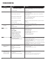
AIR FLOW BALANCING (CONT'D)
AIRFLOW STATION (GRID) METHOD
B
1 For this flow measuring station, cut
the duct and place the flow
measuring station between each
station. Make sure that the flow
measuring station’s air direction
arrow points in the direction of the
airflow. Secure the flow measuring
station with duct tape.
18”
(457 mm)
18”
(457 mm)
Measure
here
Measure
here
22
2 Before taking the reading, make sure
that the magnehelic gauge is level
and at 0. Refer to the flow
measuring station’s chart to
determine your unit’s airflow velocity.
• To avoid airflow
turbulence and incorrect
readings, the airflow
velocity should be
measured on steel
ducting a minimum of
18” (457 mm) from the
unit or elbow and before
any transition.
3 Adjust the “Supply Air Out” damper
until you reach the desired velocity.
Follow the previous steps to adjust the
“Exhaust Air Out” damper, if needed.
MAINTENANCE
CAUTION
MAKE SURE UNIT IS UNPLUGGED BEFORE ATTEMPTING ANY MAINTENANCE WORK
The following components should also be inspected regularly and well maintained.
PRACTICAL
TIPS
•To prevent electrical shock,
check that the unit is
unplugged before doing
any repairs or maintenance.
• A yearly inspection is
recommended to ensure
the efficiency and troublefree use of your system.
Run through the system
and verify the different
operating modes.
The motor - The motors are
factory balanced and lubricated for life. They require
no maintenance.
The unit - The inside of the
unit should be vacuumed
yearly. Be careful not to
damage any of the mechanical components and electrical connections.
The drain pan and drain line Units with drain lines should
have their line and connection checked regularly.
Outside hoods - The outside
hoods need to be checked
every season to make sure
there are no leaves or insects
blocking the airflow. Check
regularly that there are no
pollutants near the intake
hood. Make sure they are
clear of any snow accumulation during the winter months.
Filters need to be checked regularly
FILTERS
The filters (2) need to be
checked and cleaned every
three months or when they
appear dirty. Wash in warm
sudsy water (mild detergent)
or use a soft brush vacuum.
The filters should be replaced
when they can no longer be
cleaned properly.
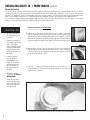
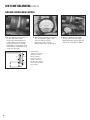
HEAT RECOVERY CORE
The heat recovery core needs to be checked and cleaned every six months. The core can be
cleaned using a mild soap and water. Rinse thoroughly. Handle with care. Hot water and a strong
detergent will damage the heat recovery core. It is recommended to clean the core in the summer
or when the temperature is mild. Never clean the heat recovery core during winter.
Clean Core and Filters Every 3-6 Months.
Unplugged before doing any repairs or
maintenance
a) Open access door.
b) Carefully grip ends of core and pull evenly out
ward. Core may be snug, but will slide
out of the channel.
c) Once removed from the cabinet remove filters.
d) Wash core in warm soapy water (do not use dishwasher).
e) Install the clean filters.
f) Install clean core.
To Install the Clean Core and Filters.
a) First mount the bottom flange of the core guide into the
bottom channel approximately 1/4” (6mm).
b) Mount the left or right side flange of the core guide
approximately 1/4 “ (6mm) followed by the other side.
c) Mount the top flange of the core guide into the top
channel approximately 1/4” (6mm).
d) With all four corners in place and the core straight and
even, push hard in the center of the core until the core
stops on the back of the cabinet.
NOTE: Some products may not be exactly as illustrated in Installation, Operation and Maintenance manual.
23
TROUBLESHOOTING
Problem
Causes
Solutions
Air is too dry
Dehumidistat control is set too low
Increase the desired level of humidity. Change ventilation mode from
continuous mode to standby.
HRV out of balance
Balance HRV
Dehumidistat control is set too high
Reduce the desired level of humidity. Combine this step with use of continuous exchange mode.
Sudden change in temperature
Wait until outside temperature stabilizes (winter). Heating will also
improve situation.
Storing too much wood for heating
Store a majority of your wood outside. Even dried, a cord of wood contains more than 20 gallons of water.
Air is too humid
Dryer vent exhaust is inside home
HRV out of balance
Open curtains or blinds. Bay or bow windows may require mechanical
method.
Balance HRV
Well sealed basement door is closed
Open the door or install a grill on the door.
Persistent condensation
on window
Improper adjustment of dehumidistat
control
HRV out of balance
Reduce the desired level of humidity. Combine this with the use of continuous exchange mode.
Balance HRV
Poor Air Flows
-1/4” (6mm) mesh on the outside hoods
is plugged
-Filters plugged
-Core obstructed
-House grilles closed or blocked
-Dampers are closed if installed
-Poor power supply at site
-Ductwork is restricting HRV
-Improper speed control setting
-HRV airflow improperly balanced
-Clean exterior hoods or vents
-Remove and clean filter
-Remove and clean core
-Check and open grilles
-Have electrician check supply voltage at house
-Check duct installation
-Increase the speed of the HRV
-Have contractor balance HRV
Supply air feels cold
-Poor location of supply grilles, the airflow
may irritate the occupant
-Outdoor temperature extremely cold
-Locate the grilles high on the walls or under the baseboards, install
ceiling mounted diffuser or grilles so as not to directly spill the supply
air on the occupant (eg. Over a sofa)
-Turn down the HRV supply speed. A small duct heater (1kw) could be
used to temper the supply air
-Placement of furniture or closed doors is restricting the movement of
air in the home
-If supply air is ducted into furnace return, the furnace fan may need to
run continuously to distribute ventilation air comfortably
-Balanced HRV
HRV and / or Ducts
Frosting up
-HRV air flows are improperly
balanced
-Malfunction of the HRV defrost
system
-Note: minimal frost build-up is expected on cores before unit initiates
defrost cycle functions
-Have HVAC contractor balance the HRV
Condensation or Ice
Build Up in Insulated
Duct to the Outside
-Incomplete vapor barrier around
insulated duct
-A hole or tear in outer duct covering
Poor air circulating near windows
24
Arrange outside vent for dryer.
-Tape and seal all joints
-Tape any holes or tears made in the outer duct covering
-Ensure that the vapor barrier is completely sealed.
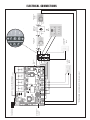
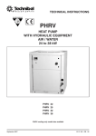
Custom defrost
mode jumper
selection
3 position mode
selection switch
-+
* Wiring diagram of complete unit inside of access panel
U
(Open & Closes contact when HRV/ERV is ON/OFF)
Accessory Control Contact
3 wires
Air Quality
Sensor
Diagnostic
LED
2 wires
(up to 5 timers)
15-minute timer
Dehumidistat
2 wires
5MR
EDF5 or 2EDF2
wire (not shown)
and /
or
Mechanical
Crank Timer
2 wires
(1 only)
and /
or
Dehumidistat
On/Off
4 wires
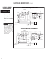
ELECTRICAL CONNECTIONS
25
ELECTRICAL CONNECTIONS (CONT'D)
ELECTRICAL CONNECTION TO A FURNACE
StandardFurnace
Accessory
Control
Contact
Standard
Interlock
Wiring
THERMOSTAT
TERMINALS
PRACTICAL TIPS
Caution:
• Never connect a 120 volt AC circuit to the terminals of the Accessory Control Contacts. Only use the low voltage class
2 circuit of the furnace blower
control.
FOUR
WIRE
W
R
G
Y
TWO WIRE
heating only
W
R
HRV
ELECTRONIC BOARD
G
C
Y
For a Furnace Connected to a
Cooling System:
• On some older thermostats,
energizing the R and G terminals at the furnace has the
effect of energizing Y at the
thermostat and thereby turning on the cooling system. If
you identify this type of thermostat, you must use the
“Alternate Furnace Interlock Wiring”.
FURNACE
24-VOLT
TERMINAL BLOCK
TWO
WIRE
COOLING SYSTEM
AlternateFurnace
Accessory
ControlWiring
Contact
Alternate
Interlock
THERMOSTAT
TERMINALS
FOUR
WIRE
W
R
G
Y
TWO WIRE
heating only
W
R
G
HRV
ELECTRONIC BOARD
WIRE JOINT
C
Y
FURNACE
24-VOLT
TERMINAL BLOCK
TWO
WIRE
26
COOLING SYSTEM
27
If you want to know your local dealer, contact:
Toronto
1155 B, Barmac Drive
North York, ON M9L 1X4
(T) 416.744.7206
(F) 416.744.7210
[email protected]
Halifax
3607, Strawberry Hill
Halifax, NS B3K 5A8
(T) 902.454.8684
(F) 902.453.5875
[email protected]
powrmatic
Ottawa
Québec
Montréal
162, Elm Street
365, Fortin
9500 BLVD. Ray-Lawson
Ottawa, ON K1R 6N5 Vill-Vanier, QC G1M 1B2
Anjou, QC H1J 1L1
(T) 613.230.7160
(T) 418.683.2708
(T) 514.493.6400
(F) 613.230.0685
(F) 418.683.8860
(F) 514.493.8722
[email protected] [email protected]
[email protected]
Item #: 401370
Rev Date: 020410
28