1
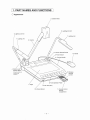
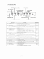
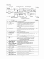
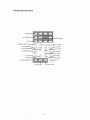
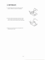
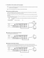
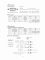
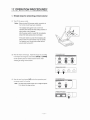
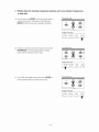
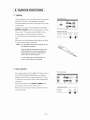
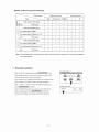
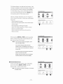
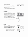
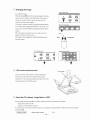
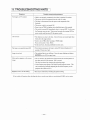
I
E: L 111.I: 0
VISUAL PRESENTER
HV-7000SX
INSTRUCTION
MANUAL
Please read this instruction manual carefully before using this Visual Presenter and keep it
for future reference.
www.touchboards.com205WestwoodAve.LongBranch.NJ077401-866-942-6273Sales@touchboards.com
11. PART NAMES
o Appearance
AND FUNCTIONS
I
3, Camera Head
6, Lighting Unit Arm
6, Lighting Unit Arm
7, Lighting Unit
14, Monitor Bracket Socket
5, Power Switch
4, Column Lock
Release Button
10, Wireless
Remote
Control
(Press this button to
raise/fold the
Colurnn.)
1, Stage
13, Mic Jack (MIC)
12, Infrared Sensor
11, Remote Control
Storage
Compartment
-6-
o Front Operation
Panel
19. Posi/Nega Conversion Button
22. Pause Button
17. Lighting Buttons
21. Zoom Buttons
18. Input Selection Buttons
-
eo
UPPER
POSUr-.EGA
...
AUTO F
2X
-
BASE
MAIN/MODE
16. Magnification Button
24. Focus Buttons
Function
RfoorePcg3
double the image size.
P.26
Part Name
Magnification
Button
25. Auto Focus Button
23. Image Rotation Button
20. Color/B&W Selection Button
16
L1
...
REal
To electronically
The image is scrolled with the direction buttons.
17
Lighting Buttons
[ <- ], [ -+
J
(Direction Buttons)
To turn ON/OFF the lighting unit.
P.20
When the image size is doubled, the image is scrolled in the arrow
direction.
18
Input Selection Buttons
To change the input line.
P.20
Main/Mode Button
If the monitor is not compatible with SXGA, this mode can be
P.21
switched in the order of SXGA
-+
XGA
-+
SVGA
---+
VGA by
changing the main body resolution.
19
Posi/Nega Conversion Button
[ ---+ ]
(Direction Button)
To show negative films.
P.24
When the image size is doubled, the image is scrolled in the arrow
direction.
20
Color/B&W Selection Button
[ ---+ ]
(Direction Button)
To present black-and-white
material, such as documents.
P.24
When the image size is doubled, the image is scrolled in the arrow
direction.
21
Zoom Buttons
To change the image size.
22
Pause Button
To temporarily hold the image.
P.25
23
Image Rotation Button
To rotate the image. Each time this button is pressed, the image
P.24
24
Focus Buttons
To adjust focus (powered).
P.23
25
Auto Focus Button
To focus automatically.
P.22
rotates counterclockwise
by 90·.
This is of one-shot auto focus system (FOCUS FREE)
-7-
P.22
o Rear Panel
27. AC Outlet
26. Power Cord
Receptacle
30. Mouse Control Terminal
29. Infrared Sensor
35. Audio-out
Terminal
33. Analog RGB Output Terminal
36. Video-in
Terminal
38. Audio-in
Terminal
1
1
..•...
.~
OJ
1 V:::O.9A
28. DC Output Terminal
,
e
[Q) e
~
31. RS-232C Terminal
Part Name
26
27
28
39. Audio-in
Terminal 2
34. Video-out Terminal
S-Video (mini DIN 4P)/
Composite-Video
(RCA pinjack)
32. USB Terminal
RtaemPcg3
Function
Power Cord Receptacle [AC IN]
AC Outlet
To connect the power cord.
To supply power up to 400W (Not interlocked with the power switch).
DC Output Terminal
[OUTPUT]
To output 12VDC. Any applicable equipment up to O.9A can be
connected.
The optional LCD Color Monitor (LM-SOlIN)
or
ELMO Desk-top Presenter (HD-80XG) can be connected with the
supplied DC cable.
Note: Do not connect
29
any equipment
other than ELMO HD-
80XG.
The light receiver of the wireless remote control. When operating
Infrared Sensor
P.ll
the Presenter from behind, aim the wireless remote control at this
light receiver.
30
Mouse Control Terminal
To connect the supplied mouse.
31
[MOUSE CONTROL]
RS-232C Terminal
[RS-232C]
Note: A serial type mouse is connected.
To connect a PC with an RS-232C cable to control the Presenter from
32
USB Terminal
[USB]
the rc
Note: This terminal is disabled if the USB terminal is used
for controlling the Presenter.
To connect the supplied USB cable to control the image transfer and
the Presenter by using the supplied CD-ROM [Image Mate for USB].
Note: This terminal
33
Analog RGB Output Terminal
[OUTPUT-RGB OUT]
34
Video-out Terminal
[OUTPUT-S-VIDEQlVIDEOj
35
is disabled
if the RS-232C terminal
is
used for controlling the Presenter.
To connect RGB input equipment, such as an LCD Projector and a
Multi-SYNC Monitor, to outnut the image.
To connect a NTSC/PAL conformable monitor, such as a TV
monitor and the optional LCD Color Monitor (LM-SO IIN), to
S- Video (mini DIN 4P)
Composite-Video (ReA pinjack)
output the image.
Audio-out Terminal
To connect audio input equipment to output the audio.
rOUTPUT-AUDIO]
36
Video-in Terminal I
Video signal from this terminal is output through the analog RGB
37
[INPUT-RGB1 ]
Video-in Terminal 2
output terminal when input selection is set at RGB 1.
Video signal from this terminal is output through the analog RGB
[INPUT-RGB2]
Audio-in Terminal 1
[INPUT-AUDIO (L I R)1]
output terminal when input selection is set at RGB2.
38
39
Audio-in Terminal 2
[INPUT-AUDIO
(L I R)2]
Audio signal from this terminal is output through the audio-out
terminal when input selection is set at RGB I.
Audio signal from this terminal is output through the audio-out
terminal when input selection is set at RGB2.
-8-
P.31
o Wireless
Remote Control
40. MENU
41. POINTER
43. Directions
42.2X
~
45. IMAGE ROTATION
~44.PAUSE
46. POSI/NEGA
49. BASE
47. COLOR/B&W_,...-...,;-...:_~c......
~ __ ~~-t_48.UPPER
50. MAIN/MODE
~~
~
52. RGB2
'-li;;;;;;"-"';;;=~+-51. RGB1
~~~
".---:::::::...
•••••-56. FAR
•.••••
~-L 55. NEAR
4--1--57.
58. IRIS NORMAL
59. IRIS OPEN
60. IRIS CLOSE
-9-
AF
I 4. SETTING UP
I
(I) Unfold the lighting unit arms fully until they come to the
deadend.
Unfold arm 1 and then arm 2 as illustrated.
(2) Press the column lock release button, and raise the column
until the column lock release button returns to the original
position.
Make sure that the column has been locked properly.
(3) Plug the power cord into the power cord receptacle of the
Presenter and the AC outlet.
-12 -
o Connection to the monitor and the projector
Note:
Be sure to turn OFF the power supply to all equipment before making any connections to protect the Presenter
and all the connected equipment.
Note:
Hold the cable plug part when connecting or disconnecting the cables .
• Connection
to the RGB-in terminal
Connect the ROB output terminal of the Presenter to the ROB input terminal of the equipment with the supplied
ROB cable or a ROB connection cable available on the market.
If the display image shifts from the center, manually adjust the horizontallvertical
equipment.
positions through the connected
If vertical stripes appear on the screen with the use of video projector, it may be improved by manually adjusting the
dot-clock frequency of the projector.
Note:
I Reference
The resolution of the Presenter can be selected according to the resolution of the equipment to be
connected.
Page
I
. Resolution
selection
P.21
Projector
AUDIO(lJR)1
@o
OJ
• Connection
Monitor
AUOIO(UR)2
@o
to the composite video-in terminal
Use the supplied RCA video/audio cable.
Monitor
AUOIO(VAII
@o
OJ
• Connection
AUOI()(lfl'l)2
@o
to the S-video-in terminal
Connect the S-video-out terminal (mini DIN 4P) of the Presenter to the S-video-in terminal of the monitor.
For the S-video mode, use the supplied 4P mini DIN cable or an S-video connection cable available on the market.
If the equipment to be used is provided with a Y/C separate connector, a conversion adapter is necessary.
~
OJ
[oj
Monitor
•
[QJ~@
AUOIO(l.lRll
@o
e
12V""1:l.9A
AUDIO(lJR}2
@o
~
~
-13 -
o RGB input signal
• Signal assignment
Input signal
5
4
3
2
o
0
0
0
®®®CV®
o 0 000
Video signal
0
Analog
Horizontal synchronizing
15 14 13 12 11
Vertical synchronizing
DSUB 15P shrinking terminal
(Female)
signal
signal
Composite syncronizing
signal
O.7V(p-p)
75Q
TIL level
(positive / negative polarity)
TIL level
(positive / negative polarity)
TIL level
(positive / negative polarity)
• Pin arrangement
Pin No.
Name
Pin No.
Name
Pin No.
Name
1
Video input (Red)
6
GND (Red)
11
GND
2
Video input (Green)
7
GND (Green)
12
NC
3
Video input (Blue)
8
GND (Blue)
13
Horizontal synchronizing/
4
NC
9
NC
5
GND
10
GND
o RGBoutput
composite synchronizing signal
14
Vertical synchronizing signal
15
NC
signal
• Signal assignment
(DSUB 15P shrinking terminal)
Pin No.
Name
Pin No.
Name
Pin No.
Name
1
Video output (Red)
6
GND (Red)
11
GND
2
Video output (Green)
7
GND (Green)
12
NC
3
Video output (Blue)
8
GND (Blue)
13
Horizontal synchronizing signal
4
NC
9
NC
14
Vertical synchronizing signal
5
GND
10
GND
15
NC
.Connection
of analog RGB cable
Presenter side
(DSUB 15P)
RGB input terminal
unit side
(BNC)
DSUB 15P shrinking
terminal (Male)
Video output (Red)
2 3 4 5
0 0
0
0
Video output (Green)
2
Video output (Blue)
3
0
R signal
4
0
Green
®CV®®®
0 0
Red
GND
0 0
11 12 13 14 15
5
GND (Red)
6
GND (Green)
7
GND (Blue)
8
G signal
Blue
B signal
9
GND
10
GND
11
synchronizing
signal
13
Vertical synchronizing
signal
14
12
Horizontal
15
Horizontal synchronizing signal
0
Vertical synchronizing signal
0
-14
-
I 5. OPERATION PROCEDURES
o Simple
I
steps for presenting printed material
(I) Turn ON the power switch.
Notes: . Before turning ON the power switch, connection
to
the monitor should have been completed .
. The indication
operation
lamp (green LED) on the front
panel shows the initial setting condition
of
each function of the Presenter.
After the power switch is turned ON, the indication
lamp of the main camera only is illuminated .
. If the power switch is turned ON immediately
being turned OFF, the Presenter
For restarting,
seconds
after
may not operate.
turn ON the power switch several
after turning OFF.
(2) Place the object on the stage. Adjust the image size according
Front operation panel
...
to the object size using the zoom buttons [TELE] and [WIDE]
•• Z Z
••
.--TElE
PAUSE
on the operation panel or wireless remote control, while
watching the image on the monitor.
IrvtAGE
Wireless
(3) Press the auto focus button [AF] on the front operation panel
NEAR
L..-.-
ROTATION
Front operation panel
••
••
ZOOM--o
WIOE
Note:
The auto focus function works up to a height of approx.
10 cm above the stage surface.
FAR
OCVS
~
,
Wireless remote control
-17-
FOCUS
remote control
AUTO FOCUS
or remote control for focusing.
ZOOM-----,
WIDE
....
FAR
-----.J
o Simple steps for showing transparent
material, such as overhead transparency
or slide film
(1) Press the base button [BASE] on the front operation panel or
wireless remote control. The indicator of the base button
[BASE] will blink, and the built-in baselight will light up.
Front operation panel
- Y...
e
-
POSIlf>..'EC-.A
UPPER
o
2X
o
COt...CR/B&W
BASE
•••
Wireless remote control
POSI/NEGA COlOR/B&W
UPPER
BASE
,--0
__0__0_.
(2) To present a nega film, press the posi/nega conversion button
[POSVNEGA]
on the front operation panel or wireless
_S~
-
Front operation panel
•••
RGIlI
--
UPPER
D
remote control to change the mode to nega.
e
...
BASE
RGB2
Wireless remote control
POSI/NEGA COLOR/8&W
UPPER
BASE
~._o__ o__ o-----,
(3) To turn OFF the baselight, press the base button [BASE] on
Front operation panel
- ••
the front operation panel or wireless remote control.
•••
2X
•••
UPPER
Y
...
BASE
POSVNEGA
o
o
co...ORt8&W
Wireless remote control
POSI/NEGA COLOR/B&W
UPPER
BASE
,--o
__ o_o__ ~
-18-
o Storing the Presenter
Note:
The Presenter can not be stored with the LCD monitor
(optional)
attached.
monitor (optional)
Before storing, detach the LCD
and monitor bracket (optional),
if connected.
(1) Turn OFF the power switch, and unplug the power cord and
the video cable.
(2) Press the column lock release button, and fold down the main
column.
Note:
The illustration
column.
shows the storage position of the
Never apply excessive
force to the column.
(3) Fold down the lighting unit arms 3 and 4. Be sure to fold
down arm 3 first as per the illustration.
-19 -
I
6. VARIOUS FUNCTIONS
I
o Lighting
The upper lighting unit for presenting material such as printed
matter and 3-D object, and the baseJight for presenting
transparent material, such as slide, and negative film, are built
in the Presenter.
Depending on the material to be presented, press the button
[UPPER] or [BASE] on the front operation panel or wireless
remote control. The indication lamp will blink for a few
Front operation panel
- a.a
-
UPPER
Wireless remote control
POSI/NEGA COLOR/B&W
seconds, and then the fluorescent lamp will light up.
POSIf\.'EC..A
2X
UPPER
BASE
L-O--°---------cCf-Cf
To turn OFF the lamp, press the button for the respective
lamp.
It has been so set before shipment that the lighting unit lights
up when the power supply is turned ON.
Notes:
. It is impossible
the baselight
to have the upper lighting unit and
lit up together .
. When the lightness of the material surface is not
sufficiently
high or a 3-D object is presented,
sharp image with good color rendering
a
can be
obtained with the upper lighting unit .
. To reduce glare, attach enclosed
stickers, as
shown, to the outside ends, of toplights.
o Input selection
Front operation panel
The respective images from two different A V sources, such as
•.•
PC and ELMO Presenters [HD-80XG], can be alternately
R(,,'l81
~~
presented on the Monitor by simply selecting the A V source
~~
.... -
XGA SVGA VGA
!
I
I
•••
-
by pressing the input selection button without changing cable
connections.
RG62
Press the input selection button [RGB1] I [RGB2] on the
I
MAINJM)QE
front operation panel or wireless remote control.
When the input is selected, the signal is outputted as shown in
Wireless remote control
MAIN/MODE
the following page.
L--...O
__
- 20-
RGBl
~._~
RGB2
• Table of video-in/out
terminal selections
Video-out terminal
Input
~
r±
Main camera video signal
ill.....!
1-«
~z
Mic.
Monaural
Main cameravideo signal
L
RGB
Composite
S-VIDEO
0
0
0
-
-
-
-
-
0
0
-
0
0
-
-
R
G
B
1
Audio-out terminal
R
Ext. video signal1
RGB1
0
-
-
-
-
Ext. audio signal1
Stereo1 (LI R)
-
-
-
0
0
Mic.
Monaural
-
-
-
0
0
-
0
0
-
-
Main cameravideo signal
R
G
Ext. video signal2
RGB2
0
-
-
-
-
B
2
Ext. audio signal2
Stereo2 (L / R)
-
-
-
0
0
Mic.
Monaural
-
-
-
0
0
Note:
The Composite-Video Terminal and the S-Video Terminal receive the image from the main camera regardless
of the input selection.
o Resolution
selection
,
Front operation panel
When the built-in camera/mode
button [MAIN/MODE]
,
on the
•••
ROO
front operation panel or wireless remote control is pressed, the
~
~
resolution of the built-in camera is switched.
I
- -. ....
SXGA
,
If the monitor is not compatible with SXGA, the resolution of the
built-in camera is switched to other in the order of SXGA XGA -
SVGA -
R-_OO_2
'1'
Wireless remote control
is pressed.
Then, the LED of the selected resolution of all 4 LEDs on the
button [MAIN/MODE]
on the front
operation panel lights up to indicate the selected resolution.
-21-
SVGA
PAUSE
VGA
1
~~,_---~---R-OT-AT-~~
VGA each time the built-in camera/mode
button [MAIN/MODE]
built-in camera/mode
L-
•••
••
•• ••
XGA
o Zoom
Front operation panel
Press the zoom button [TELE] on the front operation panel or
wireless remote control, and the image will gradually be
enlarged.
AtJTOF
.•.
r-ZOOM----'
TRE
WIDE
-7. ••
D
••
NEAR
~
FOCUS
--'
FAA
Wireless remote control
_b------l
AA
~_D_WIDE
_D_NEAR
I
Front operation panel
Press the zoom button [WIDE] on the front operation panel or
AUTO F
r---ZOOM--'
TElE
WlOE
•• 7.-
wireless remote control, and the image will be gradually
reduced.
••
t>.EAR
L..--
D
FOCUS
FAR
----.J
Wireless remote control
lL---b_
ELE
_~=----=b=EAR
--=6=-1
o Focus
.Auto
Focus
To operate Auto-Focus,
Front operation panel
press the auto focus button [AF]
on the front operation panel or wireless remote control, and
the Auto-Focus will be activated.
While the auto-focus is in operation, the indication lamp
ZOOM----'
WIDE
••••
•• ••
t'EAA.
L--
blinks until the object is brought into focus.
FOCUS
FAA
---I
Wireless remote control
-22 -
,
AUT
,----TELE
FOCU
The Presenter features a one-push auto focus function.
Once
focusing is completed, the auto focus function is released, and
the focused position maintains unchanged. (FOCUS FREE)
To obtain sharper image, zoom in on the object in the auto-
Front operation panel
focus mode while pressing the zoom button [TELEJ on the
AUT
F
r-ZCX)M----'
f£LE
WIOE
front operation panel or wireless remote control.
-'!'
m _
However, the objects listed below may not be brought into
NEAR
'---
focus in the auto focus mode. In these cases, use the manual
focus mode.
FOCUS
----'
•
FAR
Wireless remote control
Objects bearing little contrast
TELE
Objects with fine repeated patterns, such as lateral stripes
and cross stripes
NEAR
WIDE
FAR
.,---CJ
__ c)_CJ~
Objects glittering or reflecting strong light
Objects with bright background, or excessive contrast
Objects in a dark picture plane
Objects located near and far away at the same time
Objects in motion
Front operation panel
-"- -.,-
If the focus button [NEAR] or [FAR] on the front operation
panel or wireless remote control is pressed during the auto
focus, the auto focus will be released.
Notes:'
The auto focus functions
up to approx. 10cm
NEAR
'---
above the stage surface.
of out of focus.
FOCUS
•••
•
FAR
-----J
Wireless remote control
. If the camera head gets heavy shock by
accident, there is a possibility
AUTO F
r--ZOOM-o
TaE
WlOE
In
such a case, once turn the power OFF and then
re-set to ON .
1L---~_cS_~~
. It may take some time to bring the camera into
focus in the auto focus mode.
Roughly bring the camera into focus manually
and then press the auto focus button [AF].
Front operation panel
• Powered Manual Focus
To focus on any part of the material, such as 3-D material,
press the focus button [NEAR] or [FAR] on the front
-- ••••
...
PAUSE
'----ZOOM--'
TELE
WIDE
9
CD
-~-~-
operation panel or wireless remote control.
Note: The manual focus works up to approx. 10cm above
the stage surface.
IMAGE ROTATION
NEAR
Wireless remote control
- 23-
L.-
FAR
FOCUS
--..J
o PosilNega
conversion
Front operation panel
-
To show a negative film.
lPPER
Press the posi/nega conversion button [POSI! NEGA] on
o
POSI/NEGA
o
the front operation panel or wireless remote control, and the
-&-
o
image will be converted accordingly.
ca..OO'8&W
BASE
•••
To return to the normal (POST) mode, press the posi/nega
conversion button [POSI!
NEGA] again.
••
....
RGe2
Wireless remote control
POSI/NEGA COLOR/B&W
UPPER
BASE
~,.---o__ o_o---...J
o Color/B&W
selection
Front operation panel
To present the B&W (Black&White)
D
material such as
monitor, set to color mode for normal use.
To change to B&W mode, press the colorlB&W selection
o
button [COLOR I 8&W] on the front operation panel or
••••
wireless remote control.
selection button [COLOR!
8&W] again.
-yO
ca...aV8&W
BASE
Wireless
To return to normal (COLOR) mode, press the colorlB&W
f>OSIJt£GA
UP""R
documents in sharper image with no color blur on the
-~
••-
RGel
X(3.0
RGe2
remote control
POSI/NEGA COLOR/B&W
UPPER
BASE
L--O
__ ~'_O__ O_
o Image rotation
..•
When the image rotation button [IMAGE ROTATION] on
the Front Operation Panel or Wireless Remote Control is
pressed, the image rotates.
Each time the image rotation button [IMAGE ROTATION]
is pressed, the image rotates counterclockwise
by 90°.
••
•• •• ••
PAUSE
~~
XGA SVGA VGA
F' .• •• -
,
'I'
,
MAlN/~
-41IMAGE ROTATION
~ZOOM
TElE
NEAR
'---
FOCUS
Wireless remote control
When the image is rotated by 90° or 270° , the screen can be
scrolled in the up/down direction.
For further information,
refer to "Video pointer" on P.2S.
IMAl'f ROTATI(l\I
PAUSE
~_O__
Mouse
- 24-
-------,
o Iris
Wireless remote control
The iris can be manually adjusted.
AF
To open the iris, press the manual iris button [OPEN].
C)
To close the iris, press the manual iris button [CLOSE].
In the manual mode, the iris is fixed regardless of the change in
lightness of object.
The initial setting is "auto iris."
Note:
For the information of adjusting by means of the OSD,
see P.29 .
o Video pointer
When the pointer button [POINTER] on the wireless remote
Wireless remote control
control is pressed or the left button of the mouse is clicked, the
video pointer appears.
The video pointer is moved by using the direction buttons on the
wireless remote control or front operation panel of the Presenter
or by clicking and dragging the left button of the mouse.
When the pointer button [POINTER] on the wireless remote
Mouse
control is pressed or the left button of the mouse is clicked, the
video pointer disappears.
Note:
The video pointer is switched to the moving pointer
when the image is electronically magnified or rotated
(90' / 270' ) and the screen is scrolled.
o Pause
When the pause button [PAUSE] on the front operation panel or
Front operation panel
wireless remote control is pressed, the image of the main camera
::
is stored in pause mode.
When the pause button [PAUSE] is pressed again, the pause
mode is released.
..
-le- ...
PAUSE
IMAGE
RQTATI()I\,I
- -•.
.--ZOOM----,
TELE
WlDE
NEAR
L--
Note: Ifthe image is paused, the pause is released by
switching the resolution or rotating the image. When the
image is paused, Color/B&W switching is disabled.
-25 -
FOCUS
FAR
-----l
ro~ct?-------Wireless remote control
o Enlarging
the image
Front operation panel
,
To double the image.
.•.
-
When the button [2X] on the front operation panel or wireless
remote control is pressed or the right button of the mouse is
clicked, the image is doubled, and at the same time, the
scrolling (moving) pointer appears.
The screen is scrolled (moved) by using the direction buttons
UPPER
o
SASE
CQLffi/B&W
o
o
2X
•••
POSIINEGA
••
Wireless remote control
or by clicking and dragging the left button of the mouse. The
screen can be scrolled within the shooting area of the built-in
camera.
When the pointer is placed at the corner of the screen, the
Mouse
image is scrolled toward the corner.
The image can be enlarged only within the shooting area of
Scroll
the main camera.
+\
E"'acgemoo'
U
Front operation panel
...
2X
.••
PQSI/I\'EG/\
UPPER
o
o
o
COLCfVB&W
BASE
•••
o LCD monitor
+
••
+
bracket socket
LCD monitor
The LCD monitor bracket socket is used for attaching an
LCD monitor (optional) with an LCD monitor bracket
(optional).
For the connection method and cables, refer to the
instruction manual of the LCD monitor.
o About the PC software
LCD monitor
bracket
"Image Mate for USB"
When the application [Image Mate for USB) is installed, the following operation are enabled:
. Image data transfer to the PC
Operation of the Presenter by the PC
For further detail, refer to the installation manual for the application [Image Mate for USB) and the file [rnanual.pdf]
in the
CD-ROM.
I Reference
Page
I
P.30
. USS/RS-232C selection
- 26-
I 9. TROUBLESHOOTING
Symptom
No Images on TV monitor
HINTS
Possible cause/countermeasure
• Cable is not properly connected to the video-in terminal of monitor.
• The power cord is disconnected
from the wall AC outlet.
• The plug is disconnected from the power cord receptacle of the
Presenter.
• The power switch is not turned ON.
• Zoom is set at TELE to display only white/black part of the material.
• The switch is turned ON immediately after it is turned OFF. In (his case,
the Presenter may not start. Wait several seconds after turning OFF the
power switch, and then turn ON the power switch.
Out of focus
• The object is too close to the lens. Check if it does not stand higher than
IOcm above the stage surface.
• Zoom is set at TELE after focusing at WIDE angle.
Focus on the point of max. TELE.
• In the auto-focus, focusing is difficult in some cases.
The lamp is not quickly turned ON
• For protection purposes, the lamp is turned ON after preheating for 2
seconds. This is not a fault.
Image is too dark
• The ambient light is not sufficient.
Press the upper lighting unit button
[UPPER] to turn ON the upper lamp.
Moire pattern appears on the screen
image
• This is caused by the interference fringe between the meshed pattern of
the object and the CCD elements. This is normal.
This may be reduced by changing the projecting range.
• Vertical stripes may appear on the liquid crystal projector screen. This
can be reduced by manually adjusting the dot clock frequency on the
projector side. (Refer to P.13)
Brightness tone is off the setting
• This may be reduced by, switching the gamma setting.
If the trouble still remains after checking the above, consult your dealer or an authorized ELMO service center.
-35 -