1
M
MBER 917.255441
OWNER'S
MANUAL
o Assembly
o Operation
Customer Responsibilities
®Service and Adjustments
• Repair Parts
\
CAUTION:
Read and follow
all safety rules and instructions
before operating
this equipmen[
SAFETY RULES
Safe Operation
Practices for Ride-On Mowers
IMPORTANT: THIS CUTTING MACH INE IS CAPABLE OF AMPUTATING HANDS AND FEET AND THROWING OBJECTS.
FAILURE TO OBSERVE THE FOLLOWING SAFETY INSTRUCTIONS COULD RESULT IN SERIOUS INJURY OR DEATH°
L
GENERAL
•
Read, understand, and follow all instructions in the manual
and on the machine before starting..
Only allow responsible adults, who are familiar with the
instructions, to operate the machine_
Clear the area of objects such as rocks, toys, wire, etc._,
which could be picked up and thrown by the blade.
Besure the area is clearof other people before mowing, Stop
machine if anyone enters the area,
Never carry passengers.
Do not mow in reverse unless absolutely necessary. Always
look down and behind before and while backing.
Be aware of the mower discharge direction and do not point
it at anyone. Do not operate the mower without either' the
entire grass catcher or the guard in place.
Slow down before turning.
Never leave a running machine unattended. Always turn off
blades, set parking brake, stop engine, and remove keys
before dismounting..
Tum off blades when not mowtng_
Stop engine before removing grass catcher or unclogging
chute..
Mow only in daylight or good artificial light.
Do not operate the machine while under the influence of
alcohol or drugs..
Watch for traffic when operating near or crossing roadways.
Use extra care when loading or unloading the machine into
a trailer or truck
°
•
•
•
=
•
°
•
•
o
•
•
•
•
Ii.
SLOPE
OPERATION
i11. CHILDREN
Tragic accidents can occur if the operator is not alert to the
presence ofchildren. Children are often attracted to the machine
and the mowing activity, Neverassume that children will remain
where you last saw them,
*
•
Keep childrenout of the mowing area and under the watchful
care of another responsible adult.
Be alert and turn machine off if children enter the area_
o
Before and when backing, look behind and down for small
children,
°
Never carry children, They may fail otf and be seriously
injured or interfere with safe machine operation_
Never alIow children to operate the machine.
Use extra care when approaching blind corners, shrubs,
trees, or other objects that may obscure vision,
°
°
IV. SERVICE
°
°
•
OPERATION
°
Slopes are a major factor related to loss-of-control and tipover
accidents which can result in severe injury or death. Alt slopes
require extra caution, if you cannotback upthe slope or ifyou feel
uneasy on it, do not mow it.
,,
DO:
°
°
°
•
°
•
Mow up and down slopes, not across
Remove obstacles such as rocks, tree limbs, etc
Watch for holes, ruts, or bumps_ Uneven terrain could
overturn the machine. Tall grass can hide obstacles°
•
Useslow speed. Choose a low gear so that you will not have
to stop or shift while on the slope.,
°
Follow the manufacturer's recommendations for wheel
weights or counterweights to improve stabiiityo
,
Use extra care with grass catchers or other attachments
These can change the stability of the machine,
°
Keep all movement on the slopes slow and gradual Do not
make sudden changes in speed or direction."
°
Avoid starting or' stopping on a slope. If tires tose traction,
disengage the blades and proceed slowly straight down the
slope.,
DO NOT:
°
Do not turn on slopes unless necessary, and then, turn slowly
and gradually downhill, if possible.
•
Do not mow near drop-offs, ditches, or embankments., The
mower could suddenly turn over if a wheel is over the edge
of a cliff or ditch, or if an edge caves in.,
•
Do not mow on wet grass. Reduced traction could cause
sliding,
°
Do not try tostabilize the machine by putting your foot on the
ground.
°
Do not use grass catcher on steep slopes.
•
°
Use extracare in handlinggasoline and other fuels. They are
flammable and vapors are explosive_
Use only an approved container.
Never remove gas cap or' add fuel with the engine
running, Allow engine to cool before refueling, Do not
smoke.
Never refuel the machine indoors.
Never store the machine or fuel container inside where
there is an open flame, such as a water heater°
Never run a machine inside a closed area.
Keep nuts and bolts, especially blade attachment bolts, tight
and keep equipment in good condition..
Never tamper with safety devices
Check their proper
operation regularly..
Keep machine free of grass, leaves, or other debris build-up.
Clean oil or fuel spillage_ Allow machine to cool before
stodngo
Stop and inspect the equipment if you strike an object.
Repair, if necessary, before restarting,.
Never make adjustments or' repairs with the engine running.
Grass catchercomponents are subject towear, damage, and
.deterioration, which could expose moving parts or allow
objects to be thrown. Frequently check components and
replace with manufacturer's recommended parts, when necessary_
Mower blades are sharp and can cut. Wrap the blade(s) or
wear gloves, and use extra caution when servicing them..
Check brake operation frequently_ Adjust and service as
required.
..................
I
A
i H llJu,Jllu
tant safety
precautions.
It means
CAUTION!!!
BECOME ALERT!i!
YOUR
Look!or
symbolto point out imporSAFETY this
IS INVOLVED.
, ,, ,, ,,,,,,,,,
CAUTION:
Always disconnect
spark
plug wire and place wire where it cannot
contact spark plug in order to prevent
accidental
startin_t when setting up,
transporting,
adjusting
or making
repairs.
2
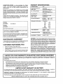
PRODUCT
CONGRATULATIONS
on your purchase of a Sears
Tractor.. It has been designed, engineered and manufactured to give you the best possible dependability and
performance°
Should you experience any problem you cannot easily
remedy, please contact your nearest Sears Authorized
Service Center/Department,
We have competent, wetltrained technicians and the proper tools to service or repair
this unito
Please read and retain this manual The instructions will
enable you to assemble and maintain your unit property_
Always observe the "SAFETY RULES"..
MODEL
NUMBER
SPECIFICATIONS
HORSEPOWER:
t2,5
GASOLtN E CAPACITY
AND TYPE:
5 QUARTS
UNLEADED REGULAR
OIL TYPE (API-SG):
SAE 30 (above 32°F)
SAE 5W-30 (below 32°F)
OIL CAPACITY:
3.0 PINTS
SPARK PLUG:
(GAP: .0XX")
CHAMPION RJ-19LM
STD361458
VALVE CLEARANCE:
INTAKE:
..005"- .007"
EXHAUST: _009" - .0t 1"
GROUND SPEED (MPH):
FORWARD:
1st
2nd
3rd
4th
5th
6th
REVERSE:
917°255441
SERIAL
NUMBER
DATEOF PURCHASE
THE MODELAND SERIAL NUMBERS WILL BE FOUND
ON A PLATE UNDER THE SEAT°
YOU SHOULD RECORD BOTH SERIAL NLJMBERAND
DATE OF PURCHASE AND KEEP IN A SAFE PLACE
FOR FUTURE REFERENCE..
MAINTENANCE
RESPONSIBILITIES
o
Read and observe the safety rules.
o
Follow a regular schedule in maintaining, caring for and
using your unit,
Follow the instructionsunder"Customer Responsibilities" and "Storage" sections of this owner's manual
=
TIRE PRESSURE:
FRONT:
REAR:
14 PSI
t2 PSt
CHARGING SYSTEM:
3 AMPS BATTERY
5 AMPS HEADLIGHTS
BLADE BOLT TORQUE:
30-35 FT..LBS.
WARNING: This unit isequipped with an internalcombustion engine and should not be used on or near any unimproved forest-covered, brush-covered or grass-covered
land unless the engine's exhaust system is equipped with
a spark arrester meeting applicable local or state laws (if
any).. If a spark arrester is used, it should be maintained in
effective working order by the operator_,
AGREEMENT
A Sears Maintenance Agreement is available on this producto Contact your nearest Sears store for details..
CUSTOMER
1_.02
1_.35
210
3.14
4.OO
5._!2
1.58
In the state of California the above is required by law
(Section 4442 of the California Public Resources Code).
Other states may have similar laws., Federal laws apply on
federal lands° A spark arrester for the muffler is available
through your nearest Sears Authorized Service Center/
Department (See REPAIR PARTS section of this manual),
LIMITED TWO YEAR WARRANTY ON ELECTRIC START RIDING EQUIPMENT
For two (2) years from the date of purchase, if this riding equipment is maintained, lubricated and tuned up according to the
instructions in the owner's manual, Sears will repair or replace, free of charge, any parts found to be defective in material or
workmanship.
This Warranty does not cover:.
•
•
•
-
Expendable items which become worn during normal use, such as blades, spark plugs, air cleaners and belts..
Tire replacement or repair caused by punctures from outside objects, such as nails, thoms, stumps, or glass°
Repairs necessary because of operator abuse, negligence, improper storage or accident or the failure to maintain the
equipment according to the instructions contained in the owner's manual
Riding equipment used for commercial or rental purposes..
LIMITED
90 DAY WARRANTY
ON BATTERY
For ninety (90) days from date of purchase, if any battery included with this tiding equipment proves defective in material or
workmanship and our testing determines the battery will not hold a charge, Sears will replace the battery at no charger
WARRANTY SERVICE 1S AVAILABLE BY RETURNING THE RIDING EQUIPMENT TO THE NEAREST SEARS SERVICE
CENTER/DEPARTMENT IN THE UNITED STATES.
This Warranty gives you specific legal rights, and you may also have other rights which may vary from state to state.
SEARS, ROEBUCK
AND CO., D/817 WA, HOFFMAN
3
ESTATES,
ILLINOIS
60179
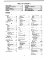
TABLE OF CONTENTS
SAFETY RULES ............................................................. 2
OPERATION ........................................................... 11_14
PRODUCT SPECIFICATIONS ....................................... 3
MAINTENANCE SCHEDULE ...................................... 15
CUSTOMER RESPONSIBILITIES ..................... 3, 15-19
SERVICE AND ADJUSTMENTS ............................ 20-25
WARRANTY
....................................................................
3
STORAGE ....................................................................
26
TABLE OF CONTENTS ................................................. 4
TROUBLESHOOTING ............................................ 27-28
INDEX ..............................................................................
4
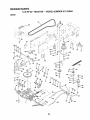
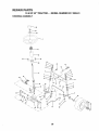
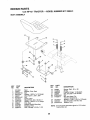
REPAIR PARTS - TRACTOR ................................. 30-47
TRACTOR ACCESSORIES ........................................... 5
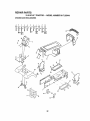
REPAIR PARTS ,_ENGINE ..................................... 48-52
ASSEMBLY .............................................................. 7-10
PARTS ORDERING/SERVICE ................... BACK PAGE
INDEX
A
E
O
Accessories .......................................................
5
Electrical:
Oil:
Adjustments:
Interlocks and Relays ........................
24
Cold Weather Conditions ............
13,17
Brake .............................................. 22
Schematic .............................................
29
Engine ................. ....................................
17
Carburetor .......................................25
Wiring Diagram ...................................
30
Storage ........................................................
26
Mower:
Engine:
Operation .....................................................
11-14
Front-To-Back .....................................
21
Air Filter .................................................
18
Operating Mower ..........................................
13
Side-To-Side ....................................
21
Air Screen .....................................................
18
Options:
Throttle Control Cable .................. 24
Cooling Fins, Engine ............................
18
Accessodes ..............................................
5
Air Filter, Engine ..............................................
18
Oil Change ......................................................
17
Spark Attester ..................................
3,40
Air Screen, Engine ........................................
18
Oil Level .................................................
13,17
P
Assembly ........................................................
7-10
Oil Type ...................................................
17
Parking Brake ........................................
11-i2
B
Preparation ......................................13
Parts Bag .................................................................
6
Battery:
Repair Parts .................................
48-52
Pads, Replacement/Repair ................
30-47
Charging ..........................................................
8
Starting ...............................................
14
Product Specifications ....................................
3
Cleaning ......................................................
17
Storage ................................................
26
R
Installation .......................................................
9
F
Levels ......................................................
8,17
Filters:
Repair Parts ..............................................
30-47
Preparation ...........................................
8
Air .............................................................
18
S
Starting with Weak Battery .......... 23
Fuel ..............................................................
19
Safety Rules ..............................................................
2
Storage .......................................................
26
Fuel:
Seat ........................................................................
8
Term_als ......................................................
!7
Type ...............................................................
13
Service and Adjustments .....................
20-25
Boils:
Sto rage ........................................................
26
Brake .................................................................
22
Motion Drive
Fuse ......................................................................
24
Carburetor
.....................................................
25
Removal/Replacement ................
22
G
Fuse .........................................................
24
Mower Blade Drive
Gauge Wheels ..................................................
9
Hood
Removal/Installation
.............
24
Removal/Replacement ...................
22
H
Motion Drive Belt
Blade:
Hood Removal/Installation .......................
24
Removal/Replacement ............22
Sharpening ...........................................
16
Mower
Blade Drive Belt
L
Replacement ...................................16
Removal/Replacement ...................
22
Leveling Mower Deck .........................................
21
Brake Adjustment ............................................
22
Mower Adjustment:
Lubrication Chart ..................................................
15
C
Front-to-Back ......................................
21
M
Carburetor Adjustment .....................................
25
Side=to-Side ..........................................
21
Maintenance Schedule ........................ 15
Controls, Tractor, .................................................
11
Mower
Installation
..................................
20
Mower:
Customer Responsibilities ..................
15-19
Mower Removal ................................
20
Adjustment,
Front-to-Back
.............
2
1
Engine:
Tire Care ....................................
8,16,23
Air Filter .................................................
18
Adjustment, Side-to-Side ...............
21
Slope
Guide
Sheet
................................55
Blade Sharpening ................................
16
Air Screen, Engine .........................
18
Spark Piugs .................................................
19
Blade Replacement ................................
16
Battery .........................................17
Specifications
......................................................
3
Cutting Height .........................................
12
Cooling Fins, Engine .................18
Starting the Engine ....................................
13-14
Installation
............................................
20
Engine Oil ..............................................
!7
Steering Wheel ..................................................
7,23
Fuel Filter ..................................................
19
Operation ..............................................
13
Stopping the Tractor, ......................................
12
Remova!
...................................................
20
Spark Plugs .............................................
19
Storage ........................................................................
26
Tractor:
Mowing Tips .............................................
14
T
Muffler ............................................................
19
Blades ................................................................
16
Thrott(eControl' Cab(e Adjustment ......24
Lubrication Chart ...........................
!5
Spark Arrestor ....................................
3,40
Tires ...............................................................
8,t6,23
Mulchel: Plate .....................................................
10
Maintenance Schedule ................
15
Trouble
Shooting
Chart
.......................
27-28
Tire Care ....................................
8,16,23
Cutting Height, Mower _..........................12
Transaxle Repair Parts .....................46-47
W
Warranty ................................................................
3
Wiring Diagram ..........................................
30
Wiring Schematic .............................................
29
4
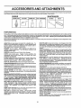
ACC
AND ATTACHMENTS
These accessories and attachments were available throughmost Sears retail outlets and service centers when the tractorwas purchased.
Most Sears stores can order these items for you when you provide the model number of your tractor°
ENGINE
SPARK PLUG
MAINTENANCE
GAS CAN
ENGINEOIL
FUEL STABILIZER
BLADES
BELTS
PERFORMANCE
Sears offers a wide variety of attachments that fit your tractor. Many of these are listed belowwith brief explanations of howthey can help
you, This list was current at the time of publication; however, it may change in future years - more attachments may be added, changes
may be made in these attachments, or some may no longer be available or fit your model, Contact your nearest Sears store for the
accessories and attachments that are available for your tractor.
Most of these attachments do not require additional hitches or conversion kits (those that do are indicated) and are designed for easy
attaching and detaching
SNOW BLADE forsnow removal only. 14-inch high, 42-inch wide
blade clears 38-inch path when angled left or right,, Raises, lowers
with side lever, Adjustable skids; replaceable, reversible scraper
bar_ (Use with tire chains and wheel weights andlor rear drawbar
weight.)
SNOWTHROWER has 40-inch swath.. Drum4ype auger handles
powdery and weVheavy snow. Mounts easily with simple pin
arrangement. Discharge chute adjusts from tractor seat.. 6qnch
diameter spout discharges snow 10 to 50 feel Lift controlled at
tractor seat. (Use with chains and wheel weights and/or rear
drawbarweight.)
SPRAYERS use 12-volt DC electric motor that connects to the
tractor battery or other 12-volt source_ Includes booms for
automatic spraying and hand held wand for spot spraying. Wand
has adjustable spray pattern. For applying herbicides, insecticides, fungicides and liquid fertilizers,
SPREADER/SEEDERS make seeding, fertilizing, and weed kilF
ing easy. Broadcast spreaders are also useful for granular deicers and sand.
SWEEPERS let you collect grass clippings and leaves.
TILLER has 5 hp engine and 36-inch swath to prepare seed beds,
cultivate and compost garden residue,. Tilter has its own built-in
lift anddepth control system and does NOT require a sleeve hitch°
Fits any lawn, yard or garden tractor° Simply hook up to the tractor
drawbar and go! Optional
accessories convert unit for
dethatching, aerating, hillingooowithout tools.
TIRE CHAINS are heavy duty; closely spaced extra-large cross
links give smooth ride, outstanding tract=on.
TRACTOR CAB has heavy duty vinyl fabric over tubular steel
frame, ABS plastic top; clear plastic windshield offers 360 degree
visibility, Hinged metal doors with catch. Keeps operator warm
and dry. Remove vinyl sides and windshields for use as sun
protector in summery Optional accessories include; tinted/
tempe red solid safety glass windshield with hand operated wiper;
12-volt amber caution light for mounting on cab top..
VACS for powerful collection of heavy grass clippings and leaves..
Optional wand attachment to pick up debris in hard4o-reach
places, VAC/CHIPPER includes a chipper-shredder.
WEIGHT BRACKET for drawbar for snow removal applications.
Uses (1) 55 lb..weight.
WHEEL WEIGHTS for rear wheels provide needed traction for
snow removal or doztng heavy materials.
AERATOR promotes deep root growth for a healthy lawn.. Tapered 2,5-inch steel spikes mounted on 10-inch diameter discs
puncture holes in soil at close intervals to let moisture soak in.,
Steel weight tray for increased penetration..
BAGGER lets you collect grass clippings and leaves for a
healthier, nearer looking lawn. Two Permanex containers hold
30-gallon plastic bags..
BUMPER protects front end of tractor from damager
CARTS make hauling easy° Variety of sizes available, plus
accessories such as side panel kits, tool caddy, cart cover,
protective mat and dolly..
CORING AERATOR takes small plugs out of soil to allow moisture and nutrients to reach grass roots. 36-inch swath. 24
hardened steel coring tips, 150 Ib. capacity weight tray,.
EASY OIL DRAIN VALVE makes oil changes easier, faster.
FRONT NOSE ROLLER cantersin front of mower deck to reduce
chances of "scalping" on uneven terrain.
GANG HITCH lets you tow 2 or 3pull-behind attachments at once,
such as sweepers, dethatchers, aerators (not for use with rollers,
carts or other heavy attachmenls)o
GAUGE WHEELS on both sides of the mower deck reduce
chances of"scalping" on uneven terrain_ For mower decks notso
equipped°
MULCH RAKE/DETHATCHER loosens soil and flips thatch and
matted leaves to lawn surface for easy pickup.. Twenty spring fine
teeth° Useful topreparebare areasforseeding. Available for front
or rear mounting.
HIGH PERFORMANCE REEL-ACTION
SPRING TINE DETHATOHER covers 36-inch wide path and
tosses thatch into large hopper Mounts behind tractor.
MULCHING CLOSE-OUT PLATE KIT, once installed, lets you
mulch, discharge or bag clippings (bagger optional) without
changing blades. For mod,,elsnot equipped as 3-in-! Convertible
mowers. See MOWER in the Repair Parts section of this
manual,
RAMP TOPS AND FEET let you load and unload tractor from a
pickup truck Use with 2 x 8 or2 x 10 lumber.
ROLLER for smoother lawn surface, 36-inch wide, 18-inch
diameter water-tight drum holds up to 390 Ibs, of weight., Rounded
edges prevent harm to turf, Adjustable scraper automatically
cleans drum.
5
....... : ..........................................
illllllllll
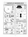
Parts Bag contents
i Ill
III
i ii,i
..........
shown full size
llllluulmlll
Parts packed separately
'llll
in carton
O
Seat
Metal
(2)
Screws
Sheet
#10-16 x t/2
O
(1) Locknut 3/8_24
(1) Large Flat Washer
(1) Shoulder Bolt 5/16-18
Steering
Wheel
Battery
Steering
Boot
(1) Hex Bolt 1/2-13 x 1
t
I
I
I
Owner's Manual
Parts Bag
I
..........
:: ......
ii iiil,,r'rll
ii,lull"
L_I
Parts bag contents
(1) Lock Washer t/2
(2) Shoulder
Bolts
@
(2) Screws #10 x 5/8
(2) Locknuts
3/8-16
Steering
Wheel
Insert
(2) Lock Washers #10
,,i,i
i,ill
not shown full size
©
(1) Washer 17/32 x 1-3/16 x 12 Gauge
t tuitttt
(_(2)
Washers
3/8
x 7/8
x 14 Gauge
Steering
Wheel
Adapter
(2) Gauge
Wheels
(2) Weld Nuts #10 L_J
(2) Washers 3/16 x 3/4 x 16 Gauge
i i
i llll
LJ
.............
k
Assemblys
,
!
t
I
I
(2) Hex Nuts 1/4-20
t
,,
_
f
t
(2) Washers 9/32 x 5/8 x 16 Gauge
..................
', "_..........
.......................
(2) Hex Bolts 1/4-20 x 3/4
&
Bushing
Steering
(@
15 ° Slope Sheet
(2) Lock Washers ...
!/4
6
Battery Caps
and Instructions
IIm
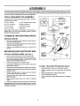
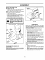
ASSEMBLY
Your new tractor has been assembled at the factory with exception of those parts left unassembled for shipping purposes+
To ensure safe and proper operation of your tractor all parts and hardware you assemble must be tightened securely. Use
the correct tools as necessary to insure proper tightness_
TOOLS
REQUIRED
FOR ASSEMBLY
A socket wrench set will make assembly easier Standard
wrench sizes are listed.
(I) 5/16" wrench
(1) 3/4" Socket w/drive rachet
(2) 7/16" wrenches
Phillips Screwdriver
(1) 1/2" wrench
Tire pressure gauge
(1) 9/16" wrench
Utility knife
When right or left hand is mentioned in this manual, it
means when you are in the operating position (seated
behind the steering wheel)+
WHEEL
TO REMOVE
TRACTOR
FROM CARTON
,,
°
Remove all accessible loose parts and parts cartons
from carton (See page 6).
Cut, from top to bottom, along lines on all four corners
of carton, and lay panels flat,,
STEERING
SHAFT
POSITION)
Check for any additional loose parts or cartons and
remove.
BEFORE ROLLING
ATTACH STEERING
TRACTOR
SCREW
TABS
STEERING
BOOT
UNPACK CARTON
•
BUSHING
ADAPTER
OFF SKID
WHEEL (See Fig. 1)
°
Slide the steering bushing over the steering shaft++
=
Raise steering shaft forward until screw holes in dash
line up with steering bushing. Install two (2) sheet
metal screws and tighten securely,
=
°
Position steering boot over steering shafL
Place tabs of steering boot over tab slots in dash and
push down to secure.
o
°
Slidesteeringwheeladapterontouppersteeringshaft,,
Position front wheels of the tractor so they are pointing
straight forward
•
Position steering wheel so cross bars are horizontal
(reff to right) andslide onto adapter.
°
Assemble large flat washer and 3/8-24 Iocknut and
tighten securely.
=
Snap steering wheel insert into center of steering
wheel+
FIG. 1
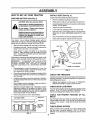
TO ROLL
TRACTOR
OFF SKID
(See Fig. 8)
Raise attachment lift lever to its highest position+
=
•
.
°
° Remove protective plastic from tractor hood and grill+
IMPORTANT:CHECK FOR AND REMOVE ANY STAPLES
tN SKID THAT MAY PUNCTURE TIRES WHERE UNIT IS
TO ROLL OFF SKID,
7
Release parking brake by depressing clutch/brake
pedal+
Place gearshift lever in neutral (N) position.
Roll unit backwards off skid+
Remove banding holding discharge guard up against
tractor+
LY
HOW TO SET UP YOUR
PREPARE
.........................
BATTERY
/
i
TRACTOR
INSTALL
SEAT (See Fig. 3)
Adjust seat before tighteningadjustment boll
(See Fig. 2)
....................
CAUTION: Wear eye and face shield.
Wash hands or clothing immediately if
accidentally in contactwith battery acid.
°
=
Remove cardboard packing on seat pan°
Place seat on seat pan and assemble shoulder bolt.
•
Assemble adjustment bolt, lockwasher and flatwasher
loosely. Do not tighten.
Tighten shoulder boltsecureiy.
•
Do not smoke. Fumes from charged
battery acid are explosive.
Read the instructions included with the
battery vent caps. Always wear gloves,
clothing and goggles to protect your
hands, skin and eyes.
°
=
Lower seat into operating position and sit on seat.
Slide seat untit a comfortable position is reached which
allows you to press clutchfbrake pedal all the way
down
°
Get off seat without moving its adjusted position.
•
Raise seat and tighten adjustment bolt securely
Your tractor has a battery charging system which is
sufficient for norma! use° However, periodicchargingofthe
battery with an automotive charger will extend its life_
o
See instructions packed with vent caps in parts bag.
•
Fill battery with acid_ Fill each cell until it reaches the
bottom of the vent weltso Do not overfill.
°
Allow battery to stand and settle for at least thirty
minutes,. After standing, check the battery cell acid
level If below the vent wefts, add more acid until the
correct level is reached_
SEAT
SEAT PAN
SHOULDER
BOLT
While battery is standing (after adding acid) and later, while
battery is being charged, continue with assembly of unit.,
IMPORTANT:
TO MAXIMIZE
THE LIFE OF YOUR
BATTERY, IT IS NECESSARY THAT THE BATTERY BE
CHARGED
BEFORE
USE. FAILURE
TO CHARGE
BATTERY CAN RESULT IN A SHORTENED
BATTERY
LiFE
•
°
.
,
o
•
LOCK WASHER
ADJUSTMENT
BOLT
Charge battery at a rate of 6 amperes for I hour_ Use
a 12 volt battery charger. Observe all safety precautions required for battery charging..
Check the acid level after the battery is charged. If the
acid has fallen below the correct level, add distilled or
iron free water_
FIG. 3
CHECK TIRE PRESSURE
The tires on your tractor were ovednflated at the factory for'
shipping purposes. Correct tire pressure is important for'
best cutting performance.
Install the vent caps to cover the vent welt& Wash the
top of the battery with water to remove any acid, then
wipe dry°
Check battery case for leakage to make sure that no
damage has occurred in handling
Dispose of excess battery acid° Neutralize acid for
disposal by adding it to two gallons of water in a five
gallon plastic container. Stir-with a wooden or' plastic
paddle while adding baking soda until the addition of
more soda causes no more foaming_
Follow instructions on how to install battery.
CUT AWAY VIEW
/i,
LARGE FLAT WASHER
•
Reduce tire pressure to PSI shown in "PRODUCT
SPECIFICATIONS" on page 3 of this manual°
CHECK DECK LEVELNESS
For best cutting results, mower housing should be properly
leveled. See "TO LEVEL MOWER HOUSING" in the
Service and Adjustments section of this manual.
CHECK
BELTS
VENTCAP
FOR PROPER
POSITION
OF ALL
See the figures that are shown for replacing motion and
mower blade drive belts in the Service and Adjustments
section of this manual. Verify that the belts are routed
correctly.
BATTERY
CHECK BRAKE SYSTEM
LEVEL
FIG. 2
After you learn how to operate your'tractor, check to see
that the brake is properly adjusted, See ''TO ADJUST
BRAKE" in the Service and Adjustments section of this
manual
8
LY
,,,
INSTALL BATTERY
,
, ,,
,,,
,,
,,,, ,,,,,,,
,,,
, ,
(See Figs. 4 and 5)
i =ill=
/
ijl=
CAUTION: Do not short battery terminals. Before installing battery, remove
metal bracelets, wristwatch bands,
rings, etc.
Positive terminal must be connected
first to prevent sparking from accidental grounding.
•
Lift seat to raised position°
Open battery box door.
•
Be sure battery drain tube is attached to battery box.
•
Lower battery into battery box with battery terminals
toward front of uniL
•
First connect RED battery cable to positive (+) terminal
with hex bolt, flat washer, lock washer and hex nut as
shown. Tighten securely,.
Connect BLACK grounding cable to negative (-) terminal with remaining hex bolt, flat washer, lock washer
and hex nut° Tighten securely_
•
°
BATTERY
BOX DOOR
VENT CAPS
Close battery box door°
FIG. 5
Open battery box door for:
o Inspection for secure connections (to tighten hardware)°
°
°
Inspection for corrosion_
Testing battery°
ASSEMBLE GAUGE
DECK (See Fig. 6)
.
Jumping (if required)_
o
Periodic charging
Assemble gauge wheels with tractor on a flat level surface.
° Adjust mower to desired cutting height (See 'q-O ADJUST MOWER CUTTING HEIGHT" in the Operation
section of this manual).
o With mower in desired height of cut position, gauge
wheels should be assembled so they are slightly off the
ground° Install gauge wheel in appropriate hole with
shoulder bolt, 3/8 washer, and 3/8-16 Iocknut and
tighten securely,
° Repeat for opposite side installing gauge wheel in
same adjustment hole.
BATTERY
BOX DOOR
NEGATIVE
(BLACK) CABLE
POSITIVE
(RED) CABLE
GAUGE WHEEL
MOUNTING
BRACKET
LOCK WASHER
HEX
BOLT
3/8-16
LOCKNUT
3/8 WASHER
POSITIVE (+) TERMINAL
WHEELS
GAUGE WHEEL
NEGATIVE (-) TERMINAL
FIG. 4
9
_
TO MOWER
L
illl
iilll
ill
i i i
ill
ill
ill
ill
illlllllllllllll
MBLY
l llll
INSTALL
MULCHER
(See Figs. 7A & 7B)
,
llllllllllllllll,lllllllllllllllll
ill ii
PLATE
DEFLECTOR
SHIELD
Install two latch hooks to mulcher plate using screw,
washer, lock washer, and weld nut as shown.,
NOTE: Pre=assemble weld nut to latch hook by inserting
weld nut from the top with hook pointingdown°
•
=
Tighten hardware securely..
Raise and hold deflector shield in upright position
°
=
Place front of mulcher plate over front of mower deck
opening and slide into place, as shown_
Hook front latch into hole on front of mower deck.,
=
Hook rear latch into hole on back of mower deck_
LATCH
HOOKS
CAUTION: Do not remove discharge
guard from mower. Raise and hold
guard when attaching mulcher plate
and allow it to rest on plate while in
operation.
WELD NUT FROM THE TOP
FIG. 7B
/ CHECKLIST
HOOK POINTS DOWN
BEFORE YOU OPERATE AND ENJOY YOUR NEW
TRACTOR, WE WISH TO ASSURE THA T YOU RECEIVE
THE BESTPERFORMANCE AND SATISFACTION FROM
THIS QUALITY PRODUCT.
WELD
PLEASE REVIEW THE FOLLOWING CHECKLIST:
LOCK
WASHER
/
All assembly instructionshave been completed..
/
No remaining loose parts in carton.
/
Battery is property prepared and charged. (Minimum
1 hour at 6 amps).
Seat is adjusted comfortably and tightened securely_
LATCH
/
LOCK
WASHER
WASHER
HOOK
4" All tires are properly inflated. (For shipping purposes,
the tires were overinflated at the factory),.
WELD
NUT
/
,/
WASHER
Be sure mower deck is properly leveled side-to-side/
front-to-rear for best cutting results.. (Tires must be
proper_y inflated for leveling)°
Check mower and drive belts. Be sure they are routed
properly around pulleys and inside all belt keepers°
/
MULCHER
PLATE
Check wiring_ See that all connections are still secure
and wires are properly clamped_
WHILELEARNING HOW TO USE YOUR TRACTOR, PAY
EXTRA A TTENTION TO THE FOLLOWING IMPORTANT
ITEMS.:
_._...
SCREW
FIG. 7A
TO CONVERT
DISCHARGING
TO BAGGING
/
/
Engine oil is at proper level°
Fuel tank is filled with fresh, clean, regular unleaded
gasoline_
/
Become familiar with all controls - their location and
function° Operate them before you start the engine,
,/' Be sure brake system is in safe operating condition.
OR
Simply remove mulcher plate and store in a safe place.
Your mower is now ready for discharging or' installationof
optional grass catcher accessory.
10
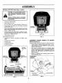
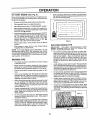
READ THIS OWNER'S
MANUAL AND SAFETY RULES BEFORE OPERATING
YOUR TRACTOR
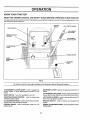
Compare the illustrations with you r tractor to familiarize yourself with the locations of various controls and adjustments_ Save
this manual for future reference°
IGNITION
SWITCH
LIFT LEVER PLLINGER
LIGHT
ATTACHMENT
LIFT LEVER
THROTTLE/CHOKE
CONTROL
ATTACHMENT
LEVER
I\1
CLUTCH/BRAKE
PEDAL
!
!
PARKING BRAKE
HEIGHT
ADJUSTMENT
KNOB
GEARSHIFT
LEVER
FIG, 8
Our tractors conform to the safety standards of the American National Standards Institute,,
ATTACHMENT CLUTCH LEVER: Used to engage the
mower blades, or other attachments mounted to your
tractor.,
GEARSHIFT LEVER: Selects the speed and direction of
tractor_
ATTACHMENT LIFT LEVER: Used to raise and lower the
mower deck or other attachments mounted to your tractor°
LIFT LEVER PLUNGER: Used to release attachment lift
lever when changing its position.
LIGHT SWITCH: Turns the headlights on and off,,
THROTTLE/CHOKE CONTROL:
controlling engine speed,
Used for starting and
CLUTCH/BRAKE PEDAL: Used fordeclutching and brak*
ing the tractor and starting the engine,,
IGNITION SWITCH:
engine,,
PARKING BRAKE: Locks clutch/brake pedal into the
brake position.
HEIGHTADJUSTMENT
cutting height_
11
Used for starting and stopping the
KNOB: Usedto adjustthe mower
OPERATION
i,,,..................
,,, .....................................
, .........
.
m
ititu
trill
tit
i=/
..........
t ttlqtttqttt
L i
tit
tt
Itllltltltll
iiit ti
The operation of any tractor can result in foreign objects thrown into the eyes, which
can result in severe eye damage. Always wear safety glasses or eye shields while
operating yourtractor or performing any adjustments or repairs. We recommend a wide
vision safety mask for over the spectacles or standard safety glasses.
I
till
......................................
_...........
t t
It
IIIttttti........
i,,_,
II
I
Itlllttlttt
HOW TO USE YOUR TRACTOR
=
Start tractor with clutch/brake pedal depressed and
gearshift lever in neutral IN) position.
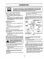
TO SET PARKING
•
Move gearshift and range shift levers to desired position.
BRAKE
(See Fig. 9)
•
Depress clutch/brake pedal intofull "BRAKE" position
and hold.
•
Place parking brake lever in "ENGAGED" positionand
release pressure from clutch!brake pedal Pedal should
remain in "BRAKE" position,. Make sure parking brake
will hold vehicle secure.
STOPPING
•
Slowly release clutch/brake pedal to start movemenL
IMPORTANT;
BRING TRACTOR TO A COMPLETE STOP
BEFORE SHIFTING OR CHANGING GEARS. FAILURE
TO DO SO WILL SHORTEN THE USEFUL LIFE OF YOUR
TRANSAXLE,_
THROTTL_
CHOKE
CONTROL
(See Fig. 9)
MOWER BLADES •
"DISENGAGED"
_OSITION
Move attachment clutch lever to "DISENGAGED" position,.
GROUNDDRIVE-
PARKING BRAKE
'ENGAGED"POSITION
"BRAKE"
POSITION
° Depress clutch/brake pedal into full"BRAKE" position,,
•
Move gearshift lever to neutral IN) position.
ENGINE •
At-I"ACHMENT CLUTCH LEVER
"ENGAGED" POSITION
GEARSHIFT
LEVER
Move throttle control to slow () posItion_
NOTE: Failure to move throttle control to slow 0 position
and allowing engine to idle before stopping may cause
engine to "backfire",,
•
Turn ignition key to "OFF" position and remove key.
Always remove key when leaving tractor to prevent
unauthorized use.
=
Never use choke to stop engine_
CLUTCHJBRAKE PEDAL
"DRIVE" POSITION
TO ADJUST MOWER CUTTING
(See Fig. 9)
Always operate engine at full throttie_
Operating engine at less than full throttle reduces the
battery charging rate,
•
Full throttle offers the best bagging and mower performance_
TO MOVE
FORWARD
°
Turn knob clockwise (F*I) to raise cutting heighL
•
Turn knob counterclockwise (_)
heighL
to lower cutting
The cutting height range is approximately 1-1/2" to 4'L The
heights are measured from the ground to the blade tip with
the engine not running. These heights are approximate
and may vary depending upon soil conditions, height of
grass and types of grass being mowed,
(See Fig. 9)
.
HEIGHT
The cutting height is controlledbyturning the heightadjustment knob in desired direction.
CAUTION: Always stop tractor completely, as described above, before leaving the operator's position; to empty
grass catcher, etc.
CONTROL
KNOB
FIG. 9
NOTE; Under certain conditions when tractor is standing
idle with the engine running, hot engine exhaust gases may
cause "browning" of grass. To eliminate this possibility,
always stop engine when stopping tractor on grass areas°
TO USE THROTTLE
HEIGHT ADJUSTMENT
•
The average lawn should be cut to approximately 2-1/2
inches during the cooJ season and to over 3 inches
during hot months. For healthier and better looking
lawns, mow often and after moderate growth,.
°
For best cutting performance grass over 6 inches in
height should be mowed tw co,, Make the first cut
relatively high; the second to desired height,,
AND BACKWARD
(See Fig, 9)
The direction and speed of movement is controlled by the
gearshift lever°
12
OPERATI
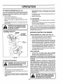
TO OPERATE
MOWER (See Fig, '10)
Your tractor is equipped with an operatorpresence sensing
switch. Any attempt by the operator to leave the seat with
the engine running and the attachment clutch engaged will
shut off the engine°
= Select desired heightof cut
°
Lower mower with attachment lift control.
°
=
i_
°
Move gearshift lever to 1st gear. Be sure you have
allowed room for tractor to roll slightly as you restart
movement.
•
To restart movement, slowly release parking brake and
clutch/brake pedal°
Make all turns slowly,.
=
TO TRANSPORT
Start mower blades by engaging attachment clutch
control,.
TO STOP MOWER BLADES - disengage attachment
clutch control
without either the entire grass catcher,
on mowers so equipped, or the dis*
CAUTION: Do not operate the mower
charge guard in place.
-
Raise attachment lift to highest position with attachment lift control..
-
When pushing or towing your tractor, be sure gearshift
lever is in neutral (N) position,.
•
Do not push or tow tractor at more than five (5) MPH.
NOTE: To protect hood from damage when transporting
your tractor on a truckor a trailer, be sure hood is closed and
secured totractoro Use an appropriate means of tying hood
to tractor (rope, cord, etc.),.
BEFORE
CHECK
STARTING
ENGINE
THE ENGINE
OIL LEVEL
(See Fig, 16)
•
The engine in your tractor has been shipped, from the
factory, already filled with summer weight oil.
•
=
Check engine oil with tractor on level ground.,
Remove oil fill cap/dipstick and wipe clean, reinsert the
dipstick and screw cap tight, wait for a few seconds,
remove and read oil level° If necessary, add oil until
"FULL" mark on dipstick is reached,. Do not overfill.
°
For cold weather operation you should change oil for
easier starting (See "OIL VISCOSITY CHART" in the
Customer Responsibilities section of this manual)_
°
To change engine oil, see the Customer Responsibilities section in this manual.
ADD GASOLINE
°
Fill fuel tank,. Use fresh, clean, regular unleaded
gasoline.. (Use of leaded gasotine will increase carbon
and lead oxide deposits and reduce valve life),
IMPORTANT: WHEN OPERATING IN TEMPERATURES
BELOW 32°F(0°C), USE FRESH, CLEAN WINTER GRADE
AsOMNE TO HELP INSURE GOOD COLD WEATHER
STARTING.
FIG. '10
TO OPERATE
,,,,,,
ON HILLS
CAUTION: Do not drive up or down
hills with slopes greater than 15° and
do not drive across any slope.
•
Choose the slowest speed before starting up or down
hills.
•
Avoid stopping or changing speed on hills°
•
If slowing is necessary, move throttle control lever to
slower position.
if stopping is absolutely necessary, push clutch!brake
pedal quickly to brake position and engage parking
brake.
•
WARNING: Experience indicates that alcohol blended
fuels (called gasohot or using ethanol or methanol) can
attract moisture which leads to separation and formation of
acids during storage. Acidic gas can damage the fuel
system of an engine while in storage. To avoid engine
problems, the fuel system should be emptied before storage of 30 days or longer. Drain the gas tank, start the
engine and let it run until the fuel lines and carburetor are
empty. Use fresh fuel next season. See Storage Instructions for additional information.
Never use engine or
carburetor cleaner products in the fuel tank or permanent
damage may occur_
illll
ii i IHHH
.......................
CAUTION: Fill to bottom of gas tank
filler neck. Do not overfill. Wipe off any
spilled oil or fuel. Do not store, spill or
use gasoline near an open flame.
'13
TO START
ENGINE
(See Fig. 9)
°
When starting engine for the first time or if engine has run
out of fuel, it will take extra cranking time to move fuel from
the tank to the engine°
=
Depress clutch/brake pedal and set parking brake.
o
Place gearshift lever'in neutral iN) position_
°
•
Move attachment clutch to "DISENGAGED" position,
Move throttle control lever' to choke its,J) positionfor
coldengine start. Forwarm engine start, move throttle
control to fast (,_) position.
•
Insert key intoignitionand turnkey clockwiseto"START"
position and release key as soon as engine starts, Do
not run starter continuously for more than fifteen
seconds per minute. If engine does not start after
several attempts, move throttle control to fast (_)
position, wait a few minutes and try again,.
•
When engine starts, move throttle control to desired
position_
•
Allow engine to warm up for a few minutes before
engaging drive or'attachments.
FIG. 11
MULCHING
°
Mower' should be properly leveled for best mow!ng
performance. See 'TO LEVEL MOWER HOUSING in
the Service and Adjustments section of this manual
The left hand side of mower should be used for trimming.
°
',
•
Drive so that clippings are discharged onto the area
that has been cut. Have the cut area to the right of the
machine This will result in a more even distribution of
clippings and more uniform cutting,
When mowing large areas, start by turning to the right
so that clippings will discharge away from shrubs,
fences, driveways, etco After one ortwo rounds, mow
in the opposite direction making left hand turns until
finished (See Fig. 11 ).
°
if grass is extremely tall, it should be mowed twice to
reduce load and possible fire hazard from dried clippings. Make first cut relatively high; the second to the
desired heighL
•
Do not mow grass when it is wet. Wet grass will plug
mower and leave undesirable clumps. Allow grass to
dry before mowing.
°
Always operate engine at full throttle when mowing to
assure better mowing performance and proper' dis*
charge of material Regulate ground speed by selecting a low enough gear to give the mower cutting
performance as well as the quality of cut desired..
TIPS
-
The special mulching blade will recut the grass clippings many times and reduce them in size so that as
they fall onto the lawn they will disperse into the grass
and not be noticed. Also, the mulched grass will
biodegrade quickly to provide nutrients for the lawn.
Always mulch with your highest engine (blade) speed
as this will provide the best recutting action of the
blades.
•
Avoid cutting your-lawn when it iswet. Wet grass tends
to form clumps and interferes with the mulchingactiono
The best time to mow your lawn is the early afternoon,
At this time the grass has dried and the newly cut area
will not be exposed to the direct sun.
,,
For best results, adjust the mower cutting height so that
the mower cuts off only the top one-third of the grass
blades (See Fig. 12)_ For extremely heavy mulching,
reduce your width of cut and mow slowly°
o
Certain types of grass and grass conditions may require that an area be mulched a second time to completely hide the clippings. When doing a second cut,
mow across or perpendicular to the first cut path,
,,
Change your cutting pattern from week to week., Mow
north to south one week then change to east to west the
next week. This will help prevent matting and graining
of the lawn.
MOWING TIPS
Tire chains cannot be used when the mower housing
is attached to unit.
MOWING
IMPORTANT:
FOR BEST PERFORMANCE, KEEP
MOWER HOUSING FREE OF BUILT-UP GRASS AND
TRASH, CLEAN AFTER EACH USE_
NOTE." If at a high altitude (above 3000 feet) or in cold
temperatures (below 32°F), the carburetor fuel mixture
may need to be adjusted forbestengine performance° See
"TO ADJUST CARBURETOR" in the Service and Adjustments section of this manual.
*
When operating attachments, select a ground speed
that will suit the terrain and give best performance of
the attachment being used..
MAX
FIG, 12
14
1/3
CUSTOMER
'""""'''''"
"'
" '"'""
"
''
'" ''""
RESPONSiBiLiTiES
'""
......................
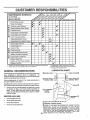
MAINTENANCE
SCHEDULE
AS YOU COMPLETE
FILL IN DATES
.REGULARSERV1CE
.__.F'_
.......
_,_
_F__,
_,._ _q,_ ,q,_ A "t-; ,-4.
_" ,.4"; _
_,
_
£,4¢ ¢_¢ _ ¢ _,,";
£_ _.4_ _,_£
SERVICE
DATESVICE
[£
£_
Check Brake Operation
_
T
CheckTire Pressure
Check for 'LooseFasteners
tp/
_
a
Sharperv'ReplaceMower Blades
_1'4
T
0
Check Batte,rY,,,,LeveltRecharge
Clean Battery and Terminals
t##'
tp/
R
CheckTransaxle cooling
c
'_'"
$/
....
_/ ...............................
€,o,
v'
.......
,
"_"
Adjust
BladeBeii'isiTension'
Adjust Motion Drive Belt(s) Tension
Check Engine Oil Level
Change
Engine
I/'5
=tl/
Oil
E C!eanAirF!.!ter
U
G
Clean Air Screen
...............
InspectMuffler/SparkArrester
I
Repl'aceOil Filter (if equipped)
N
Clean Engine coo!!ng Fins
Replace SparkPlug
:
: _'
_#'
...............
!_,3
if
....... _2'
........
V'2
tp/
...........
61_,2
__2 ........................
{b#j' 6/
ReplaceAir Filter Paper Cartridge
Replace
_/2
Fuel Filter
1 - Change more o{ten when operating under a heavy load or in high ambient temperatures
2 - Service more often when operating In didy er dusty condilions
GENERAL
"
3 - If equipped with oil filter, change o_| every 50 hours
4 _ Repface blades more ei'ten when mewing in sandy soil
5 - 1!equlpped with adjustable system
LUBRICATION
RECOMMENDATIONS
CHART
(_)SPtNDLE
The warranty on this tractordoes not cover items that have
been subjected to operator abuse or negligence, To
receive full value from the warranty, operator must maintain
tractor as instructed in this manual.
(_
Some adjustments will need to be made periodically to
properly maintain your tractor.
FRONT
BEARING
;PINDLE ZERK (_)
ZERK
All adjustments in the Service and Adjustments section of
this manual should be checked at least once each season..
®
Once a year you should replace the spark plug, clean
or replace air filter, and check blades and belts for
wear. A new spark plug and clean air filter assure
proper air-fuel mixture and help your engine run better
and last longer..
BEFORE
EACH
@
CLUTCH
PIVOT(S)
USE
•
Check engine oil level
Check brake operation_
•
•
Check tire pressure.
Check for loose fasteners,.
:RENT WHEEL (_)
BEARING ZERK
iEARSHIFT (_
PIVOTS
®
SAE 30 OR 10W30 MOTOR OIL API - SG
(_) GENERAL PURPOSE GREASE
15
® REFER TO CUSTOMER RESPONSIBILITIES "ENGINE" SECTION
IMPORTANT:
DO NOT OIL OR GREASE THE PIVOT POINTS
WHICH HAVE SPECIAL NYLON BEARINGS
VISCOUS LUBRICANTS WILL ATTRACT DUST AND DIRT THAT WILL SHORTEN
THE LIFE OF THE SELF-LUBRICATiNG
BEARINGS,
IF YOU
FEEL THEY MUST BE LUBRICATED,
USE ONLY A DRY, POWDERED GRAPHITE TYPE LUBRICANT
SPARINGLY
TRACTOR
'_
BLADE
Always observe safety rules when performingany mainte-
MANDREL
\
rlanceo
.,...,._
ASSEMB LY
BRAKE OPERATION
If tractor requires more than six (6) feet stopping distance
at high speed in highest gear, then brake must be adjusted.,
(See "TO ADJUST BRAKE" in the Service and Adjustments section of this manual).,
TRAILING
FLAT WASHER_
TIRES
.
EDGE
LOCK WASHER*_
Maintainproper air pressure in all tires (See "PRODUCT SPECIFICATIONS" on page 3 of this manual)°
o
Keep tires free of gasoline, oil, or insect control chemicals which can harm rubber.
°
Avoid stumps, stones, deep ruts, sharp objects and
other hazards that may cause tire damage.
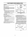
HEX BOLT
(GRADE
*A GRADE 8 HEAT TREATED BOLT CAN BE
IDENTIFIED BY SIX LINES ON THE BOLT HEAD°
FIG. 13
BLADE CARE
For best results mower blades must be kept sharp_ Replace bent or damaged bladeso
BLADE REMOVAL
TO SHARPEN
Care should be taken to keep the blade balanced_ An
unbalanced blade willcause excessive vibration and eventual damage to mower and engine.
(See Fig. 13)
.
Raise mower to highest position to allow access to
blade&
•
Removehexbolt,
blade°
=
Install new or resharpened btade with trailing edge up
towards deck as shown_
=
Reassemble hex bolt, lock washer and flat washer in
exact order as shown_
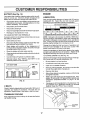
BLADE (See Fig. 14)
lockwasher and flat washersecuring
°
The blade can be sharpened with a file or on a grinding
wheel. Do not attempt to sharpen while on the mower.
°
To check blade balance, you will need a 5/8" diameter
steel bolt, pin, or a cone balancer. (When using a cone
balancer, follow the instructions supplied with balancer).
Slide blade on to an unthreaded portion of the steel bolt
or pin and hold the bolt or pin parallel with the ground.
If blade is balanced, it should remain in a horizontal
position. If either end of the blade moves downward,
sharpen the heavy end until the blade is balanced.
•
°
Tighten bolt securely (30-35 Ft. Lb& torque)_
IMPORTANT: BLADE BOLT IS GRADE 8 HEAT TREATED.
NOTE: We do not recommend sharpening blade- but ifyou
do, be sure the blade is balanced.
NOTE: Do not use a nail for balancing blade. The lobes of
the center' hole may appear to be centered, but are not.
CENTER HOLE
FIG. 14
16
/
/
ii,i
CUSTOMER
BATTERY
SIBILITIES
ENGINE
(See Fig. 15)
"Yourtractor has a battery charging system which is sufficient for normal use° However, periodic charging of the
battery with an automotive charger wil! extend its life,,
•
Acid solution level in each battery cell should be even
with bottoms of vent wells. Add only distilled or iron free
water if necessary. Do not overfiiL
.
Keep battery and terminals cleam
.
•
Keep battery bolts tight.
Keepvent capstight and smallvent holestn caps open,
•
Recharge at 6 amperes for I hour,
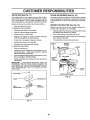
LUBRICATION
Only use high quality detergent oil rated with API service
classification SG Select the oil's SAE viscosity grade
according to your expected operating temperature.,
SAE VISCOSITY
:_0_ .......
, 0..
Corrosion and dirt on the battery and terminals can cause
the battery to "leak" power,
°
-
Open battery box door,
Disconnect BLACK battery cable first then RED battery cable and remove battery from tractor°
•
Wash battery with solution of four tablespoons of
baking soda to one gallon of water. Be careful not to get
the soda solution into the cells.
°
=
Rinse the battery with plain water and dry,
Clean terminals and battery cable endswith wire brush
until bright°
Coat terminals with grease or petroleum jelly,,
=
soo........
, 80.
_0o
°_,....
BEFORE NEXT OiL CHANGE
NOT_" Although multi-viscosity oils (5W30, 10W30 etc
improve starting in cold weather, these multi-viscosity oils
wilt result in increased oil consumption when used above
32°F. Check your engine oil level more frequently to avoid
possible engine damage from running low on oil,,
Change the oil after the first two hours of operation and
every 25 hours thereafter or at least once a year if the
tractor is not used for 25 hours in one year,,
Check the crankcase oil level before starting the engine
and after each eight (8) hours of operation,, Tighten oil fill
cap/dipstick securely each time you check the oil level,
TO CHANGE ENGINE OIL (See Fig 16)
Determine temperature range expected before oil change,,
All oil must meet API service classification SG_
Reinstall battery (See "INSTALL BATTERY" in the
Assembly section of this manual),.
VENT CAP
CUT AWAYVIEW
3o° 3=o,.o_
TEMPERAT'L/RE RANGE ANTiCiPATEO
TO CLEAN BATTERY AND TERMINALS
GRADES
VENT
WELL
BATTERY
CELL ACID
LEVEL
•
Be sure tractor is on level surface.
=
°
Oil will drain more freelywhen warm.
Catch oil in a suitable container,,
•
Remove oil fill cap/dipstick, Be careful not to allow dirt
to enter the engine when changing oil
=
°
Remove drain plug.
After oil has drained completely, replace oil drain plug
and tighten securety_
.
Refill engine with oil through oil fill dipstick tube, Pour
slowly. Do not overfill,, For approximate capacity see
"PRODUCT SPECIFICATIONS" on page 3 of this
manual
°
Use gauge on oil fill cap/dipstick for checking level Be
sure dipstick cap is tightened securely for accurate
reading,, Keep oil at "FULL" line on dipstick,
FIG. 15
V-BELTS
Check V-belts for deterioration and wear after 100 hours of
operation and replace if necessary,, The belts are not
adjustable,, Replace belts if they begin to slip from wear.,
TRANSAXLE
CAP/DIPSTICK
COOLING
Keep transaxle free from build_up of dirt and chaff which
can restrict coolingo
OIL DRAIN
PLUG
FIG. 16
'17
ill,,
CUSTOM
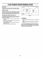
AIR FILTER (See Fig. 17)
CLEAN AIR SCREEN
Your' engine will not run properly using a dirty air fUter_
Clean the foam pre-cleaner after every 25 hours of operation or every season. Service paper cartridge every 100
hours of operatiort or every season, whichever'occu rs firsL
Air screen must be kept free of dirt and chaff to prevent
engine damage from overheating. Clean with awire brush
or compressed air to remove dirt and stubborn dried gum
fibers,
Service air cleaner more often under dusty conditions.
ENGINE COOLING
•
Remove knob(s) and cover..
TO SERVICE PRE-CLEANER
(See Fig. 18)
FINS (See Fig. 18)
Remove any dust, dirt or oil from engine cooling fins to
prevent engine damage from overheating_
-
Slide foam pre-cleaner off cartridge.
o
Wash it in liquid detergent and water'..
•
•
Squeeze it dry in a clean cloth..
Saturate it in engine oil. Wrap it in clean, absorbent
cloth and squeeze to remove excess oil.
°
•
Use compressed air' or stiff bdstle brush to thoroughly
clean engine cooling fins_
•
If very dirty or damaged, replace pre-cleaner.
.
To reassemble, reverse above procedure.
•
•
Reinstall pre-cleaner over cartridge_
°
Reinstall cover and secure with knob(s).
TO SERVICE CARTRIDGE
Remove screws from btower housing and lift housing
and dipstick tube assembly off engine,
Cover oil fill opening to prevent entry of dirt,
SCREWS
BLOWER
HOUSING
k
SCREWS
•
o
Remove cartridge nut.
Carefully remove cartridge to prevent debris from entering carburetor. Clean base carefully to prevent
debris from entering carburetor.
° Clean cartridge bytapping gently on flat surface. If very
dirty or' damaged, replace cartridge,
o Reinstall cartridge, nut, precleaner, cover and secure
with knob(s)..
IMPORTANT:
PETROLEUM SOLVENTS, SUCH AS
KEROSENE, ARE NOT TO BE USED TO CLEAN THE
CARTRIDGE.. THEY MAY CAUSE DETERIORATION OF
THE CARTRIDGE. DO NOT OIL CARTRIDGE. DO NOT
USE PRESSURIZED
AIR TO CLEAN OR DRY
CARTRIDGE.
AIR SCREEN
DIPSTICK
TUBE
ASSEMBLY
PLUG
COVER KNOB
ENGINE COOLING FINS
FIG. 18
COVER
CARTRIDGE NUT
PAPER
CARTRIDGE
FIG. 17
18
,.,.,,.., ,,,.,, ,,, ,,
CU
, ,,,,,,,,,,,
,
...............
ER RESPONSiBiLiTiES
MUFFLER
CLAMP_
Inspect and replace corroded muffler and spark arrester (if
equipped) as it could create a fire hazard and/or damage.
SPARK
CLAMP
PLUGS
Replace spark plugs at the beginning of each mowing
season or after every I00 hours of operation, whichever
occurs first. Spark plug type and gap setting are shown in
"PRODUCT SPECIFICATIONS" on page 3 of this manual,.
IN-LINE FUEL FILTER
FUEL _
FILTER ....
(See Fig. 19)
_
J
FIG. 19
The fuel _ter should be replaced once each season. If fuel
filter becomes clogged, obstructing fuel flow to carburetor,
replacement is requiredr
CLEANING
•
With engine cool, remove filter and plug fuel line
sections,.
•
.
Place new fuel filter in position in fuel line with arrow
pointing towards carburetor_.
Clean engine, battery, seat, finish, etc. of all foreign
matter,.
=
o
Be sure there are no fue! line leaks and clamps are
properly positioned.
immediately wipe up any spilled gasoline,.
Keep finished su rfaces and wheels free of all gasoline,
oil, etc..
•
Protect painted surfaces with automotive type wax.
°
We do not recommend using a garden hose to clean your
tractor unless the electrical system, muffler, air filter and
carburetor are covered to keep water out., Water in engine
can result in a shortened engine life.
'19
CAUTION:
,
=
•
o
•
BEFORE PERFORMING ANY SERVICE OR ADJUSTMENTS:
Depress clutch/brake pedal fully and set parking brake.
Place gearshift lever in neutral (N) positiom
Place attachment clutch in "DISENGAGED" position.
Turn ignition key "OFF" and remove key.
Make sure the blades and all moving parts have completely stopped.
Disconnect spark plug wire from spark plug and place wire where it cannot come in contact with
plug.
TRACTOR
TO REMOVE MOWER
CLUTCH LEVER
(See Fig. 20)
RETAINER
lING
CLUTCH ROD
Mower will be easier to remove from the right side of tractor.
.
•
Place attachment clutch in "DISENGAGED" position..
Move attachment lift lever forward to lower mower to its
lowest position,
°
Ro!l belt off engine pulley_
°
Disconnect clutch rod from clutch lever by removing
retainer spring.
=
Disconnect anti-sway bar from chassis bracket by
removing retainer' spring_
Disconnect suspension arms from rear deck brackets
by removing retainer springs.
Disconnect front links from deck by removing retainer
springs.
°
°
SUSPENSION
ARMS
SPRINGS
3OTH SIDES)
RETAINER
SPRING
•
Raise lift lever to raise suspension arms,, Slide mower
out from under' tractor,,
IMPORTANT:
IF AN ATTACHMENT OTHER THAN THE
MOWER IS TO BE MOUNTED TO THE TRACTOR, THE
R,H, AND LH, SUSPENSION ARMS MUST BE REMOVED
FROM TRACTOR,.
ANTI-SWAY
BAR
Raise attachment lift iever to its highest position°
•
Slide mower undertractor with dischargeguardto right
side of tractor,,
•
°
Lower lift fever to its lowest position.
Install mowerin reverse order of removal instructions_
RETAINER
SPRINGS
(BOTH SIDES)
FIG. 20
TO INSTALL MOWER (See Fig. 20)
.
ENGINE
PULLEY
2O
SERVICE AND ADJUSTMENTS
Hil,,i
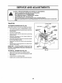
TO LEVEL MOWER
i i
i illill
HOUSING
SIDE-TO-SIDE ADJUSTMENT (See Figs° 2I and 22)
•
Raise mower to its highest position°
•
Atthe midpoint of both sides of mower, measure height
from bottom edge of mowerto ground. Distance "A" on
both sides of mower should be the same or within I/4"
of each other._
If adjustment is necessary, make adjustment on one
side of mower only.
°
To raise one side of mower, tighten lift Iink adjustment
nut on that side°
B
To lower one side of mower, loosen lift link adjustment
nut on that side.
NOTE: Three futl turns of adjustment nut will change
mower height about 1/8".
•
Recheck measurements after adjusting_
BOTTOM
BOTTOM EDGE
OF MOWER TO
EDGE
OF MOWER TO
GROUND
L
II
iiiiiiiiiiii i I
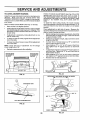
FRONT-TO-BACK ADJUSTMENT (See Figs. X3 and X4)
IMPORTANT: DECK MUST BE LEVEL SIDE-TO-SIDE, IF
THE FOLLOWING FRONT-TO-BACK ADJUSTMENT IS
NECESSARY, BE SURE TO ADJUST BOTH FRONT LINKS
EQUALLY SO MOWER WILL STAY LEVEL SIDE-TOo
SIDE_
To obtain the best cutting results, the mower housing
should be adjusted so that the front is approximately t/4" to
3/4" lower than the rear when the mower is in its highest
position,,
Check adjustment on right side of tractor_ Measure distance"D" directly in front and behind the mandrel at bottom
edge of mower housing as shown.
•
Before making any necessaryadjustments, checkthat
both front linksare equal in length,. Both links should
be approximately 10-3/8".
•
If links are not equal in length, adjust one link to same
length as other iink_
° To lower front of mower loosen nut "E" on both front
links an equal number of turns°
° When distance "D" is 1/4" to 3/4" lower at front than
rear, tighten nuts "F" against trunnion on both front
links.
•
To raise front of mower, loosen nut"F' from tnmnion or}
both front links, Tighten nut "E" on both front links an
equal number of turns.
•
When distance "D" is '1/4" to 3/4" lower at front than
rear, tighten nut"F" against trunnion on both front links_
•
Recheckside-to-sideadjustmenL
Adjust the mower while tractor is parked on level ground or
driveway_ Make sure tires are properly inflated (See
"PRODUCT SPECIFICATIONS" on page 3 of this manual).
If tires are over or underinflated, you will not properly adjust
your mower.,
•
.................. IIII'III'IIHL'J'J'ii
MANDREL
FIG. 23
FIG, 21
BOTH FRONT LINKS MUST BE EQUAL IN LENGTH
NUT
NUT "F"
LIFT LINK ADJUSTMENT
NUT
FIG. 22
FRONT LINKS
21
TRUNNION
FIG. 24
"E"
SERVICE AND ADJUSTMENTS
.......
........... _.............
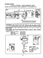
TO REPLACE
MOWER
BLADE
DRIVE
BELT
t l it ii
...............
m
ll,lll ll/
iH
Hi
i
WITHPARKINGBRAKE"ENGAGED"
(See Fig. 25)
The mower blade drive belt may be replaced withouttool&
Park the tractor on level surface° Engage parking brake,,
BELT REMOVAL•
Remove mower' from tractor (See "TO REMOVE
MOWER" in this section of this manual)°
o
Work bett off both mandrel pulleys and idler pulleys.
o
Pull best away from mower.
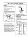
NUT"A"
JAM NUT
BELT INSTALLATION °
InstaEInew belt in reverse order of removal.
•
Make sure belt is in all pulley grooves and inside all belt
guides_
IATING
MANDREL
PULLEY
ARM
FIG. 26
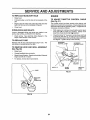
TO REPLACE
(See Fig. 27)
IDLER
MOTION DRIVE BELT
Park the tractor on level surface. Engage parking brake.
For assistance, there is a belt installation guide decal on
bottom side of left footrest.
MANDREL
PULLEY
Remove mower (See 'q_o REMOVE MOWER" in this
section of this manual°)
°
•
•
Remove
Remove
Pull belt
upwards
er&
upper belt keeper,
belt from stationary idler and clutching id[eL
slack toward rear' of tractor_ Remove belt
from transaxle pulley by deflecting belt keep-
.
Pullbelt toward front of tractor and remove downwards
from around engine pulley_
°
Install new belt by reversing above procedure,.
IMPORTANT: MAKE SURE UPPER BELT KEEPER IS
POSITIONED PROPERLY BETWEEN LOCATOR TABS.
FIG. 25
TO ADJUST
•
BRAKE (See Fig. 26)
Your tractor is equipped with an adjustable brake system
which is mounted on the right side of the transaxle_
ENGI
PULLEY
If tractor requires more than six (6) feet stopping distance
at high speed in highest gear',then brake must be adjusted._
•
Depress clutch/brake pedal and engage parking brake,
°
Measure distance between brake operating arm and
nut "A" on brake rod.
•
If distance is other than 1-1/2", disengage parking
brake, loosen jam nut and turn nut "A" until distance
becomes 1-1/2. Retighten jam nut against nut A,
°
.
Engage parking brake and recheck distance.
Road test tractor for proper stopping distance as stated
above_ Readjust if necessary,. If stopping distance is
still greater than six (6) feet in highest gear, further
maintenance is necessary. Contact your nearest authorized service center!department.
LOCATOR
TABS
CLUTCHING
IDLER
_ER BELT
KEEPER
IDLER
TRANSAXLE
PULLEY
FIG. 27
22
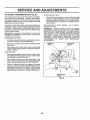
;ERViCE AND ADJUSTMENTS
iiiiii
TO ADJUST
i
i
STEERING
iiiii
ii
iiiiiii
L
iiiii
i
iiii
i
i
l
L II
WHEEL ALIGNMENT
i
The front wheel toe-in and camber are not adjustable on
your tractor° If damage has occurred to affect the front
wheel toe4n or camber, contact your nearest authorized
service center/department.
Remove axle cover, retaining ring and washers to allow
wheel removal (rear wheel contains a square key - Do
not lose),.
°
Repair tire and reassemble,
•
On rearwheels only: align grooves in rear wheel hub
and axleo Insert square key,,
°
Replace washers and snap retaining ring securely in
axle groove°
Replace axle cover,
=
n l i u ....................................
TO ATTACH JUMPER CABLES ° Connect each end of the RED cable to the POSITIVE
(+) terminal of each battery, taking care not to short
against chassis,.
•
Connect one end of the BLACK cable to the NEGATIVE (-) terminal of fully charged battery.
•
Connect the other end of the BLACK cable to good
CHASSIS GROUND, away from fuel tank and battery,
TO REMOVE CABLES, REVERSE ORDER •
°
BLACK cable first from chassis and then from the fulty
charged battery.
RED cable last from both batteries..
WASHERS
POSITIVE
RETAINING
RING
Q
AXLE COVER
J
If your battery is too weak to start the engine, it should be
recharged,.
If "jumper cables" are used for emergency
starting, follow this procedure:
IMPORTANT: YOUR TRACTOR IS EQUIPPED WITH A 12
VOLT NEGATIVE GROUNDED
SYSTEM°
THE OTHER
VEHICLE
MUST ALSO BE A 12 VOLT NEGATIVE
GROUNDED SYSTEM.
DO NOT USE YOUR TRACTOR
BATTERY TO START OTHER VEHICLES,
TO REMOVE WHEEL FOR REPAIRS
(See Fig. 28)
•
LL
ateexplosivegases, Keepsparks, flame
and
smokingLead-acid
materials batteries
away from
batCAUTION:
generteries, Always wear eye protection
when around batteries.
FRONT WHEEL TOE-IN/CAMBER
Block up axle securely,
I
TO START ENGINE WITH A WEAK BATTERY
(See Fig, 29)
If steering wheel crossbars are not horizontal (left to right)
when wheels are positionedstraightforward, remove steering wheel and reassemble per instructions in the Assembly
section of this manual.
.
ILLL
TERMINAL
NEGATIVE TERMINAL
I
"_"_ SQUARE KEY
(REAR WHEEL ONLY)
FIG. 28
CABLES
CHARGED
BATTERY
POSITIVE TERMINAL
NEGATIVE TERMINAL
FIG. 29
23
S
A
USTIVl
A
.......................
TO REPLACE
HEADLIGHT
BULB
ii
ENGINE
•
Raise hood.
•
Pull bulb holder out of the hole in the backside of the
grill.
TO ADJUST THROTTLE
(See Fig. 31)
•
Replace bulb in holder and push bulb holder securely
back into the hole in the backside of the grill.,
Close hood_
The throttle control has been preset at the factory and
adjustment should notbe necessary,, Check adjustment as
described below before loosening cable. If adjustment is
necessary, proceed as follows:
°
INTERLOCKS
AND RELAYS
=
Loose or damaged wiring may cause your tractor to run
poorly, stop running, or prevent it from starting_
°
Check wiring. See electrical wiring diagram in the
Repair Parts section of this manual.,
TO REPLACE
FUSE
HOOD
AND GRILL
CABLE
With engine not running, move throttle control lever
from slow (-_) to choke (l\l) position. Slowly move
lever' from choke (N) to fast (.€_) position_
Check that holes"A" in governor controf lever and hole
in governor plate line-up. If holes "A" are not aligned,
loosen clamp screw and move throttle cable until holes
are aligned. Tighten clamp screw securely.,
Replace with 30 amp automotive-type plug-in fuse., The
fuse holder is located behind the dash_
TO REMOVE
CONTROL
GOVERNOR
CONTROLLEVER
GOVERNOR
CONTROL
PLATE
ASSEMBLY
(See Fig. 30)
o
Raise hood.
o
°
Unsnap headlight wire connector.
Stand in front of tractor° Grasp hood at sides, tilt toward
engine and fift off of tractor:,
•
To replace, reverse above procedures..
HOLES
"A"
CLAMP
SCREW
HOOD
FIG. 31
HEADLIGHT
WIRE
CONNECTOR
FIG. 30
24
THROTI'LE
CABLE
SERVICE AND ADJUSTNIENTS
TO ADJUST
CARBURETOR
(See Fig. 32)
ACCELERATION TEST -
The carburetor has been preset at the factory and adjustment should not be necessary_ However, minor adjustment may be required to compensate for differences in fuel,
temperature, altitude or Ioado If the carburetor does need
adjustment, proceed as follows:
•
In general, turning idle mixture valve in (clockwise) decreases the supply of fuel to the engine giving a leaner fuel/
air mixture. Turning the idle mixture valve out (counterclockwise) increases the supply of fuel to the engine giving
a richer fuel!air mixture..
High speed stop is factory
damage may result.
PRELIMINARY SETTING -
•
adjusted..
Air cleaner assembly must be assembled to the carburetor when making carburetor adjustments,
Be sure the throttle control cable is adjusted properly
(see above).
i
THROTTLE
LEVER
With engine off turn idle mixture valve in (clockwise)
closing it finger tight and then turn out (counterclockwise) 1 full turn°
FINAL SETTING Start engine and allow to warm for five minutes.. Make
final adjustments with engine running and shift/motion
control lever in neutral (N) position,
•
Move throttle control lever to slow (._) position. With
finger, rotate and hold throttle lever against idle speed
screw.. Turn idle speed screw to attain 1750 RPM
°
While still holding throttle lever against idle sp.eed
screw, turn idle mixture valve in (clockwise) until engine begins to die and then turn out (counterclockwise)
until engine runs rough° Turn valve to a point midway
between those two positions. Release throttle lever°
Do not adjust
IDLE SPEED
SCREW
•
•
(,_) to fast (,_)
turn idle mixture
Repeat test and
engine acceler-
IMPORTANT:
NEVER TAMPER
WITH THE ENGINE
GOVERNOR,
WHICH IS FACTORY SET FOR PROPER
ENGINE SPEED.. OVERSPEEDINGTHE
ENGINE ABOVE
THE FACTORY
HIGH
SPEED
SETTING
CAN BE
DANGEROUS., IF YOU THINK THE ENGINE-GOVERNED
HtGH SPEED NEEDS ADJUSTING,
CONTACT YOUR
NEAREST
AUTHORIZED
SERVICE
CENTER/
DEPARTMENT, WHICH HAS PROPER EQUIPMENT AND
EXPERIENCE
TO
MAKE
ANY
NECESSARY
ADJUSTMENTS,
IMPORTANT:
DAMAGE TO THE NEEDLE VALVE AND
THE SEAT tN CARBURETOR
MAY RESULT IF SCREW IS
TURNED IN TOO TIGHT.
•
Move throttle control lever from slow
position_ if engine hesitates or dies,
valve out (counterclockwise)
1/8 turn,
continue to adjust, if necessary, until
ates smoothlyo
IDLE MIXTURE
VALVE
FIG. 32
25
STORAGE
ENGINE
Immediately prepare your tractor for storage at the end of
the season or' if the tractor will not be used for' 30 days or
more.
..........
illlll
ii
i
FUEL SYSTEM
illnill
IMPORTANT:
IT IS iMPORTANT
TO PREVENT
GUM
DEPOSITS
FROM FORMING
IN ESSENTIAL
FUEL
SYSTEM PARTS SUCH AS CARBURETOR, FUEL FILTER,
FUEL HOSE, OR TANK DURING STORAGE,
ALSO,
EXPERIENCE
INDICATES THAT ALCOHOL
BLENDED
FUELS (CALLED GASOHOL OR USING ETHANOL OR
METHANOL) CAN ATTRACT MOISTURE WHICH LEADS
TO SEPARATION AND FORMATION OF ACIDS DURING
STORAGE.
ACIDIC GAS CAN DAMAGE THE FUEL
SYSTEM OF AN ENGINE WHILE IN STORAGE.
gasoline in the tank inside a building
where fumes may reach an open flame
orAUTION:
spark. Never
Allow store
the engine
the tractor
to cool
with
before storing in any enclosure.
i_
.....
i iiiiiii I
,,
i
.......................
;:,
.......
................
TRACTOR
Remove mower from tractor' for winter storage. When
mower is to be stored for a period of time, clean it thoroughly, remove all dirt, grease, leaves, etc. Store in a
clean, dry area.
=
Clean entire tractor (See"CLEANING"in the Customer
Responsibilities section of this manual).
=
Inspect and replace belts, if necessary (See belt replacement instructionsin the Service and Adjustments
section of this manual).
Lubricate as shown in the Customer Responsibilities
section of this manual.
o
Be sure that all nuts, bolts and screws are securely
fastened. Inspect moving parts for damage, breakage
and wear'. Replace if necessary.
°
After a period of time in storage, battery may require
recharging.
=
•
°
Start the engine and let it run until the fuel lines and
carburetor are empty.
Never use engine or carburetor cleaner products in the
fuel tank or permanent damage may occur_
Use fresh fuel next season.
°
NOTE: Fuel stabilizer is an acceptable alternative in
minimizing the formation of fuel gum deposits during storage_ Add stabilizer to gasotine in fuel tank or storage
container. Always follow the mix ratio found or_ stabilizer
container. Run engine at least 10 minutes after adding
stabilizerto allow the stabilizer to reachthe carburetor. Do
not drain the gas tank and carburetor if using fuel stabilizer_
ENGINE OIL
Drain oil (with engine warm) and replace with clean engine
oil.. (See "ENGINE" in the Customer Responsibilities
section of this manual).
BATTERY
Fully charge the batter:/for storage_
Drain the fuel tank.
•
Touch up all rusted or' chipped paint surfaces; sand
lightly before painting.
•
=
CYLINDERS
To help prevent corrosion and power leakage during
long periods of storage, battery cables should be
disconnected and battery cleaned thorough ly (sea"TO
CLEAN BATTERY AND TERMINALS" in the Customer Responsibilities section of this manual).
°
Remove spark plug(s)_
=
Pour' one ounce of oil through spark plug hole(s) into
cylinder(s).
Turn ignitionkey to"START" position for a few seconds
to distribute oil
°
°
After cleaning, leave cables disconnected and place
cables where they cannot come in contact with battery
terminals.
Replace with new spark plug(s)_
OTHER
°
Be sure battery drain tube is securely attached.
°
Do not store gasoline from one season to another'.
=
if battery is removed from tractor for storage, do not
store battery directly on concrete or damp surfaces.
o
Replace your gasoline can if your can starts to rust.
Rust and/or dirt in your gasoline will cause problems..
•
If possible, store your tractor indoors and cover' it to
give protection from dust and dirt..
•
Cover your tractor with a suitable protective cover that
does not retain moisture. Do not use plastic. Plastic
cannot breathe which allows condensation to form and
witl cause your tractor to rust_
IMPORTANT: NEVER COVER TRACTOR WHILE ENGINE
AND EXHAUST AREAS ARE STILL WARM..
26
,LILILILILILIIII
II
TROU
IIUIIUIIIJ
LIIIIJ
HOOTING POINTS
PROBLEM
CAUSE
CORRECTION
Will not start
1
2,
3,,
4,
5.
6.
7,
Out of fuel,
Engtne not =CHOKED" properly
Engine flooded,
8adspark plug,
Dirty air filter.
Dirty fuel filter
Water in fuel
1,
Fill rue! tank
2,
3
4
5.
6.
7,
8,
9.
10,.
Loose or damaged wiring
Carburetor out of adjustment,
Engine valves out of adjustment
8.,
9,
10
See "TO START ENGINE" In Operation section,
Watt several minutes before attempting to stsrt.
Replace spark plug,
Clean/replace air filter..
Replace fuel filter,
Drain fuel tank and carburetor, refiII tank with fresh
gasoline and replace fuel filter,
Check all wiring,
Contact an authorized service facll_ty
Contact an aulhodzed service facility
Hard to start
1..
2,
3,
4.
5.
6.,
7.
8,
Dirty air filler
Bad spark plug,,
Weak or dead battery.
Dirty fuel filter..
Stale or dirty fuel,
Loose or damaged wiring,
Carburetor out of adjustment.,
Engine valves out of adjustment.
1.
2
3
4
5,
6,
7.
8,
Clean/replace air filter.,
Replace spark plug.
Recharge or replace battery
Replace fuel filter.
Drain fuel tank and refill wilh fresh gasoline
Check all wiring
Contact an authorized service facility,
Contact an authorized service facility,
Engine will not turn over
1.,
2,
3.
4,
5
6o
7,,
8,
9,
Clutch/brake pedal not depressed
Attachment clutch Is engaged,.
Weak or dead battery,
Blown fuse
Corroded batlery terminals.,
Loose or damaged widng,
Faulty ignition switch.,
Faulty solenoid or starter,
Faulty operator presence swtich(es)
1.
2,
3,
4,
5
6
7,
8
9,
Depress clutcr',Jbrakepedal,
Disengage attachment clutch.
Recharge or replace battery
Rap{ace fuse
Clean battery term{nals
Check aft widng
ChecWreplace lgntfion switch,
Check/replace solenoid or starter,
Contact an authorized service facility,,
Engine clicks but will not
start
1
2
3.
4,
Weak or dead battery.
Corroded battery terminals
Loose or damaged wldng
Faulty solenoid or starter
1,
2,
3,
4,
Rechargeor replace battery
Clean battery terminals,
Check allwidng.
Check/replace solenoid or starter
Loss of power
1.
2,
3
4,,
5,
6,
7.,
8,
9,
Cutting too much grass/too fast
Throttle In "CHOKE" position,
Build-up of grass, leaves and trash under mower
Dirty air filter.
Low oil levelld{rty o_L
Faulty spark plug,,
Dirty fuel ftiter.
Stale or dirty fuel
Water in fuel
1
2
3
4
5.
6
7,
8..
9.
Set tn "Higher Cut" pesittordreduce speed,
Adjust throttle control,
Clean underside of mower housing
Clean/replace air filter,,
Cheek oll levellchange oil
Clean and regap or change spark plug.
Replace fuel filter
Drain fuel tank and refifi with fresh gasoline,
Drain fuel tank and carburetor, refiII tank with fresh
gasoilne and replace fuel filter,
Connect and tighten spark plug wire
Clean engine air screen/fins
Clean/replace muffler,
Check all widng
Contact an authorized service facility.
Contact an authorized service facility.
t0,
11.
12,
I3
14,
15.
Excessive vibration
Spark plugwlre loose,
Dirty engine a_r screen!fins
Dirty!clogged muffler,
Looseor damagedwirlng,
Carburetor out of adjustment
Engine valves out of adjusimenL
I
2
Worn, bent or toose blade,
Bent blade mandrel
3.
Loose/damaged part(s)
10,
11,
t2.
t3
t4
15
t,
2.
3.
27
Replace blade, Tighten blade bolt.
Replace blade msndreL
Tighten loose part(s) Replace damaged parts
ill
TROUBLESHOOT
iiill/i,i
i i ,,...,,
i i ii
CAUSE
Engine continues to run
when operator leaves seat
with attachment clutch
1,
Faulty operator-safety presence control system_
1.
2,
3..
4,,
5,
Worn, bent or loose blade.
Mower deck not teveL
Buildup of grass, leaves, and trash under mower,
Bent blade mandrel
Clogged mower deck vent holes from buildup of
grass, leaves, and trash around mandrels
Mower blades wlll not
rotate
1
2,
3,
4,
Obstruction in clutch mechanism,
Womldamaged mower drive belt,
Frozen Idler pulley.
Frozen blade mandrel,
Poor grass discharge
1,
2,
3,
4.
5.
6,
7
8,
9
10.
11
illl.
ii
G POINTS
....
PROBLEM
illllll,
ii H,Hllll
CORRECTION
1,,
Check wiring, switches and connections, If not
corrected, contact an authorized service facility,
1,,
5,
Replace blade. Tighten biade boil.,
Level mower deck,
Clean underside of mower housing
Replace blade mandrel
Clean around mandrels to open vent holes
engaged
Poorcut-uneven
i
_, =,1Hiill
lll L LH==l,,H=
Engine speed too slow_
Travel speed tee fast.
Wet grass.
Mower deck not level
Lowluneven tire air pressure
Worn, bent or loose blade,,
Buildup of grass, Ieaves and trash under mower,
Mower drive belt worn,.
Blades Improperly installed
improper blades used_
Clogged mower deck vent hotes from buildup of
grass, leaves, and trash around mandrels_
2.
4,.
1,
Remove obstruction.
2,,
3
4
Replace mower drive bell
Replace idler pultey
Replace blade mandrel.
1
2
Place throttle control In "FAST" position,
Shift to slower speed,
Allow grass to dry before mowing.
LeveJ mower deck,
Check tires for proper air pressure,
Replace/sharpen blade Tighten blade bolt,,
Clean underside of mower housing
Replace mower ddve beLt.
Reinstall blades sharp edge down,
Replace with blades listed in tilis manual,
Clean around mandrels to open vent holes,
4.
5,.
6,
7
8,
9,-
10.
11,
llll
Headlight(s) not working
(tf so equipped)
1
2
3
4
5
Switch is "OFF"
Bulb(s) burned out
Faulty light switch
Loose or damaged wiring
Blown fuse,.
1.
Turn switch "ON",,
2
3,
4.
5,
Replace bulb(s)
Check/replace tight swilch
Check wiring and connections,
Replace fuse,
Battery will not charge
1,
2,
3
4
Bad battery cell(s).
Poor cable connections..
Faulty regurator (if so equipped)
Faulty alternator
1,
2,
Replace battery.
Check/cLean all connections
Replace regulator
Reptace altematoro
1
Engine throttle control not set at "SLOW"
position for 30 seconds before stepping engine
t
,,,,, ,,,,
.....
H
3,.
4.
,,,,............................
_,,,
Engine "backfires"
when turning engine
"OFF"
28
Move throttte control to "SLOW" position and allow
to idle for 30 seconds before stoppfng engine
12.5 HP 42" TRACTOR -- MODEL NUMBER 917.255441
SCHEMATIC
111°
BATTERY
I ......
RED
RED
FUSE 30 AMP,
STARTER
WHITE
I
i
I
WH!_E
BLACK
D
I
SOLENOID
i
(PEDAL UP)
i...... ;-i
I
I
SEAT SWITCH
(NOT OCCUPIED)
[-'3
CLUTCH 1BRAKE
f'_--L__
I
_
I
I
t
I
I
I,O
BLACK
_LACK
I-
I
i
I
SWITCH
O_
I
ql
ATT'MENT CLUTCH
(CLUTCH OFF)
SLACK
GROUNDING
CONNECTOR
SLACK
q
IGNITION
UNIT
_
CHARGING SYSTEM OUTPUT
3 AMP DC @ 3600 RPM
SPARK
PLUG
28 VOLTS AC MtN. @ 3600 RPM
(CHARGING SYSTEM DISCONNECTED)
RED
I
LtGHT|NG SYSTEM
5 AMP AC @ 3_
M
rriin
B
OUTPUT
DIODE
i ALTERNATOR
I
I
j
NOTE
t4 VOLTS AC MIN @ 360D RPM {LIGHTS OFF)
YOUR TRACTOR IS EQUIPPED
WITH A SPECIAL ALTERNATOR
5
SYSTEM° THE LIGHTS ARE
NOT CONNECTED TO THE
BATTERY, BUT HAVE THEIR
i
I
OWN ELECTRICAL SOURCE.
BECAUSE OF THIS, THE
IGNITION SWITCH
I ......
I
BRIGHTNESS OF THE LIGHTS
POSITION
CIRCUIT
WILL CHANGE WiTH ENGINE
SWITCH
_-(O
_
f-_ 7
..............
r
.........
SPEED. AT IDLE THE LIGHTS
OFF
M + G
(OFF)
__j
I z
WILL DIM. AS THE ENGINE IS
HEADLIGHTS
ON
B+L
SPEEDED UP, THE LIGHTS WILL
WIRING
INSULATED
CLIPS
START
B+ S+ L
BECOME THEIR BRIGHTEST°
NOTE: IF WIRING INSULATED CLIPS
WERE REMOVED FOR SERVICING OF
NON-REMOVABLE
---O--REMOVABLE
UNIT, THEY SHOULD BE REPLACED TO
CONNECTIONS
CONN ECTIONS
PROPERLY SECURE YOUR WIRING,,
I
29
REPAIR PARTS
12.5 HP 42" TRACTOR - - MODEL NUMBER 917.255441
ELECTRICAL
22
21
4O
I
23
I
I
42
36 38
35
8
2O
/
/
/
/
!
/
j
I
25
'I
/
1
i
2
3O
REPAIR PARTS
12.5 HP 42" TRACTOR
-- MODEL
NUMBER
917.25544'1
ELECTRICAL
KEY
NO.
1
PART
NO.
121265X
2
3
4
5
6
7
8
9
19
20
21
74760412
STD55t025
STD55!125
12t264X
STD541025
I09238X
129965
109596X
STD551125
73350400
136850
22
23
24
26
26
28
29
30
31
32
33
34
35
36
37
38
39
40
41
42
43
44
70
4152J
STD551225
4799J
132202
108824X
4207J
121305X
140399
140400
141226
140403
110712X
108236X
STD601005
I04445X
140336
109553X
140414
71110408
!3t563
t38406
73640400
140413
DESCRIPTION
Battery, 12 Volt, 25 Amp
1/4-20 UNC x 1!2
Bolt, Hex Head 1/4-20 unc x 3/4
Washer
Washer
Caps, Battery
Nut
Tube, Plastic, 12"
Box, Battery
Clamp, Hose
Washer, Lock
Nut, Hex, Jam 1/4-20 UNC
Harness, Light Socket
(Includes Key # 33)
Bulb, Light
Washer
Cable, Battery, 6 Gauge, Red, 11"
Cable, Battery, 6 Gauge, Red, 43"
Fuse, 30 Amp
Cable, Ground, 6 Gauge, Black, 12"
Switch, Plunger
Switch, Ignition
Nut, Ignition
Cover, Key Switch
Key, Ignition
Switch, Light
Bracket, Clutch Switch
Screw
Switch, Interlock, Clutch, 2 Terminal
Bracket, Interlock Switch
Switch, interlock, Clutch, 4 Terminal
Harness, Ignition
Bolt, Hex Head, Fin,_
Cover, Terminal, Red
Solenoid
Nut
Harness Engine B&S/Tec Dual
NOTE: AI! component dimensions given in U,,S, inches
1 inch = 25_4 mm
31
REPAIR PARTS
12.5 HP 42" TRACTOR
- - MODEL
NUMBER
917.255441
CHASSIS AND ENCLOSURES
A
B
C
O
E
F
G
I
L
P
21
11
Q
_26
17
30
33
13
"=G
37
31
34
32
REPAIR PARTS
12.5 HP 42" TRACTOR-CHASSIS
MODEL
NUMBER
917.255441
AND ENCLOSURES
KEY
NO.
PART
NO.
1
2
3
6
7
8
9
'10
11
12
13
14
15
140341
140356
17490612
140169
17490612
2751R
140637X013
5479J
122795X
121794X
126276X
17490608
74180512
16
17
!8
!9
21
22
24
25
26
28
29
30
31
32
33
34
35
36
37
38
39
51
53
58
STD541431
131445X459
126938X
17521310
122933X
124479X
STD523710
19131312
STD54t437
140137
124029X
140001X459
136619
17490612
105465X459
105464X459
STD533707
STD541437
105466X
139886
139887
19'131216
72I 40608
11050600
DESCRIPTION
Chassis Assembly
Drawbar
Screw, Thd.. Rollo 3/8-16 x 3/4
Saddle
Screw, Thdo Roll. 3/8-16 x 3/4
Clip,Line Fuel
Dash
Plug, Button
Panel, Dash, L.H_
Cover, Access
Panel, Dash, R.Ho
Screw Thdrol 3/8-16 x 1/2
Screw, Machine, Truss Head
5/16-18 UNC x 3/4
Nut
Hood Assembly
Bumper, Hood
Screw, Sitd Hex Hd w/PI Washer
Rivet, Ratchet, Nylon
Washer, Nylon ..28x .,75 x _19
Bolt
Washer 13/32 x t3/16 x 12 Gauge
Nut
Grill
Lens, Headlight Bar, Clear
Fender
Bracket, Fender
Screw, Thdrol 3/8-16 x 3/4
Footrest, LH.
Footrest, Roll
Bolt
Nut
Pad, Footrest, Ribbed
Pivot Bracket Assembly, L.H.
Pivot Bracket Assembly, R.H_
Washer 13/32 x 3/4 x 16 Gauge
Bolt, Carriage 3/8-16 x 3/4
Washer, Lock, External Tooth
NOTE: All component dimensions given in U.So inches
1 inch = 25.4 mm
33
_PAm_ PA_TS
DRIVE.
12.5 HP 42" TRACTOR
" " MODEL NUMBER
917.255441
66
17
18
2O
/
26
27
71
REPAIR PARTS
12,5 HP 42" TRACTOR
- - MODEL
NUMBER
917,255441
DRIVE
KEY
NO.
PART
NO.
142603
2
3
4
5
6
8
10
tl
12
13
t 10422X
t23666X
12000028
121520X
17490512
141OO3
76020416
105701X
19151216
71040412
14
t5
16
!7
18
19
20
21
22
23
24
25
26
27
28
29
3O
31
32
33
34
35
36
37
38
39
4O
41
42
43
44
45
46
STD551125
74780544
STD541431
121520X
STD523710
STD54!437
I 7490512
106933X
130804
STD541437
STD541237
106888X
STD551 O37
STD561210
140448
124236X
130807
127275X
STD523107
STD541431
122424X
120183X
STD551062
STD571810
123674X
STD523727
4470J
109070X
19131312
STD541437
105706X
110812X
12000039
DESCRIPTION
Transaxle, Dana, 6 Speed,
Model Number 4360-79
Spring, Extension, Brake
Pulley, Transaxle
Ring, Retainer
Strap, Torque, R.H.
Screw, Thdo, Roll. 5/16-18x3/4
Lever, Shift
Pin, Cotter
Washer, Shift Plate
Washer !5/32 x 3/4 x 16 Gauge
Bolt, Hex Head, Fin°
!/4-28 UNF x 3/4 Grade 8
Washer
Bolt, Hex Head 5/16-18 x2-3/4
Nut, Crownlock 5/16-18 UNC
Strap, Torque L.H.
Bolt
Nut
Screw, Thdo, Rollo 3/8-16 x 3/4
Knob
Rod, Brake
Locknut
Nut
Spring, Brake Rod
Washer
Pin
Rod, Parking Brake
Cap, Parking Brake, Red
Bracket, Transaxle
Keeper, Belt, Loll..
Bolt
Nut
Shaft Assembly, Foot Pedal
Bearing, Nylon
Washer
Roll Pin
Pulley, idler, Flat
Bolt
Spacer, Split .395 x °59
Keeper, Belt, Retainer
Washer 13/32 x 13/16 x 12 Gauge
Nut
Bearing, Nylon
Washer, Hardened
Ring, Kiip
KEY
NO.
PART
NO.
47
48
49
50
51
52
53
54
55
56
57
58
59
60
61
62
63
64
127783
123789X
123205X
STD523715
STD541437
STD551037
1057!0X
STD561210
105709X
STD561210
130801
127274X
140312
19t31312
17490612
8883R
140186
71170764
65
66
67
68
69
70
71
72
73
74
75
76
77
78
80
81
82
83
84
85
86
87
88
89
90
95
100
STD551143
129921
STD523710
19131312
STD541437
134683
STD523710
19132012
STD541437
109502X
121749X
STD581075
123583X
121748X
131488
136932
123782X
19171216
132182
73530400
71208
19212016
12000008
139964
124346X
17490612
19111216
DESCRIPTION
Pulley, Idler, V-Groove, Plastic
Bellcrank Assembty
Retainer, Belt
Bolt
Nut
Washer
Link, Clutch
Pin
Spring, Clutch Return
Pin
V-Belt, Ground Drive
Keeper, Belt, RoHo
Keeper, Belt, Center Span
Washer 13/32 x I3t16 x 12 Gauge
Screw, Thd., Roll. 3/8-16 x 3/4
Cover, Pedal
Pulley, Engine
Bolt, Hex Head, Fin.
7/16-20 x 4 Grade 5
Washer
Keeper, Belt, Engine, L.H,_
Bolt
Washer 13/32 x 13/16 x I2 Gauge
Nut
Guide, Mower Drive Belt, RH.
Bott
Washer 13/32 x 1-1/4 x 12 Gauge
Nut
Spacer, Split .80 x .94
Washer 25/32 x 1-1/4 x 16 Gauge
E-Ring
Key, Square 2.0 x .I845/o1865
Washer 25/32 x 1-5/8 x 16 Gauge
Arm, Shift
Shaft Assembly
Spring, Torsion
Washer 17/32 x 3/4 x 16 Gauge
Tie Rod
Nut, Nylock
Bushing, Pivot
Washer
E-Ring
Console, Shift, 6 Speed, N/Ignition
Nut, Self-Threading, Washer Hd 1/4
Screw, Thd,., Roll. 3/8-16 x 3/4
Washer 11/32 x 3/4 x 16 Ga°
NOTE: All component dimensions given in U.S. inches
1 inch = 25°4 mm
35
REPAIR PARTS
12.5 HP 42" TRACTOR
STEERING
- - MODEL
NUMBER
917.255441
ASSEMBLY
47
14
33
16
!
32
43
11
12
34
!
10
36
35
/ //
t!
45
REPAIR PARTS
12.5 HP 42" TRACTOR - - MODEL NUMBER 917.255441
STEERING
ASSEMBLY
KEY
NO.
PART
NO.
1
2
3
4
5
6
7
8
9
10
11
!2
13
14
15
16
17
!8
I9
20
21
22
133741
142033
135227
135228
6266H
12t748X
19272016
12000029
3366R
130468
STD551137
73610600
110438X
74011056
73901000
132624
132614
57079
124035X
126684X
STD551125
71070410
23
24
25
26
27
28
29
3O
31
32
33
34
35
36
37
38
39
4O
41
42
43
44
45
46
47
127501
109816X
124036X
12000029
136874
6266H
17490612
STD551137
73610600
130465
126847X
19131416
STD561210
132196
STD611005
133742
19133808
STD541537
104820X
124417X
121749X
121746X
12000029
121232X
6855M
DESCRIPTION
Steering Wheel
Front Axle Assembly
Spindle Assembly, LoH_
Spindle Assembly, RH.
Bearing, Race, Thrust, Hardened
Washer 25/32 x 1-5/8 x 16 Gauge
Washer 27/32 x 1-1/4 x 16 Gauge
Ring, Klip
Bearing, Steering Column
Link, Drag
Washer, Lock
Nut, Hex, Fin. 3/8-24 UNF
Spacer, Bearing, Front Axle
Bolt, Hex Head 5/8-11 UNC x 3-1/2
Nut, Lock, Flange 5/8-11 UNC
Pin, Axle 5/8 x 1.5511o54
Shaft Assembly, Steering
Washer, Thrust .515 x °750 x 4033
Support, Shaft
Washer, Shim 1/4 x 5/8 x .062
Washer
Screw, Hex Socket Head
1/4-20 x 5/8
Pittman Shaft Assembly
Nyliner, Snapdn
Bracket, Steering
Ring, Klip
Gear, Sector
Bearing, Race, Thrust, Hardened
Screw, Thd, Roll. 3/8-16 x 3/4
Washer, Lock
Nut, Hex, Fin._ 3/8-24 UNF
Rod, Tie
Bushing, Link, Drag
Washer 13/32 x 7/8 x 16 Gauge
Pin
Bushing, Steering
Screw
Insert, Steering Wheel
Washer 13/32 x 2-3/8 x 8 Gauge
Gripco Nut
Adaptor, Steering Wheel
Boot, Steering Shaft
Washer 25/32 x 1-1/4 x 16 Gauge
Washer 25/32 x 1-5/8 x 16 Gauge
Ring, Klip
Cap, Spindle
Fitting, Grease
NOTE; All component dimensions given in U_S. inches
1 inch = 25_4 mm
37
REPAIR PARTS
12.5 HP 42" TRACTOR
-- MODEL
NUMBER
917.255441
SEAT ASSEMBLY
KEY
NO,
PART
NO.
1
2
3
4
5
6
7
8
9
10
12
13
14
t27438X
140551
STD523710
19131610
140407
STD541437
124181X
t7490616
19131614
140552
121246X
121248X
72050411
KEY'
NO.
DESCRIPTION
Seat
Bracket, Pivot, Seat
Bolt
Washer' 13/32 x I x 10 Gauge
Clip, Push-In °375 x.250
Nut
Spring, Seat
Screw, Thd., Roll. 3/8-16× 1
Washer t3/32 x 1 x 14 Gauge
Pan, Seat
Bracket, Switch Mounting
Bushing, Snap
Bolt, Carriage 1/4-20 x 1-3/8
PART
NO.
15
16
17
21
22
23
134300
121250X
123976X
139888
STD541431
74780814
24
25
26
19171912
127018X
STD551150
DESCRIPTION
Spacer', Split .28 x °88
Spring
Locknut, Flange 1/4 Grade 5
Bolt, Shoulder 5/16-18 UNC
Nut
Bolt, Hex Head, Fin.
1/2-13 x 7/8 Grade 5
Washer 17/32 x 1-3/16 x 12 Gauge
Bolt, Shoulder 5/16-18 x .62
Washer, Lock
NOTE: All component dimensions given in USo inches
1 inch = 25.4 mm
38
REPAIR PARTS
12.5 HP 42" TRACTOR - - MODEL NUMBER 917.255441
DECALS
18
9
13
6
3
7
7
4
I6
10
19
5
11
8
12
13
21
14
KEY
NO.
't
2
3
4
5
6
7
8
9
10
PART
NO.
138955
127908
143735
143736
132674
133644
136332
133178
128314
137537
WHEELS
DESCRIPTION
Decal,
Decal,
Decal,
Decal,
Decal,
Decal,
Decal,
Decal,
Decal,
Decal,
Operating Instruction
HP, Engine
Hood,R.H.
Hood,L.H.
Grill, LT4000
Customer Maintenance
Side Panel, IC Gold
Mower, 3 In One
Fender, Craftsman
Caution, English
KEY
NO.
11
12
13
14
16
17
18
19
21
----
PART
NO.
4900J
109199X
131473
136830
140837
133179
132268
131265
138836
138311
144385
144386
DESCRIPTION
Decal, Clutch/Brake, English
Decal, V-Belt Drive Schematic
Decal, Chassis, 6 Speed/42"
Decal, V-Belt Schematic
Decal, Parking Brake Saddle
Decal, MowerQC System
Decal, Insert, Steering Wheel
Decal, Lightbox, Grill
Decal, Dash Lawn Tractor Sit
Decal, Lift Handle
Owner's Manual, English
Owner's Manual, Spanish
& TIRES
KEY
NO.
1
2
3
4
PART
NO.
59192
65139
t06222X
59904
106732X427
278H
9040H
106108X427
106268X
7152J
104757X
DESCRIPTION
Valve Cap, Tire
Stem, Valve
Tire, Front
Tube, Front Tire
(Not Provided, Service Item Only)
Rim, Front
Fitting, Grease (Front Wheel Only)
Bearing, Flange (Front Wheel Only)
Rim, Rear
Tire, Rear
Tube, Rear Tire
(Not Provided, Service Item Only)
Cap, Axle
REPAIR PARTS
12.5
HP 42" TRACTOR
--
MODEL
NUMBER
917,255441
ENGINE
1
27
H
D
25
,_
36
F
3
14
15
6
32
/
38
37
_'_
34
_÷'_
29
23
OPTIONAL
Spark
............................
EQUIPM
Arrester
,,
HH HHm
ENT
I'1111111
3O
B
D
E
F
G
H
I
22
18
2O
19
4O
21
REPAIR PARTS
12.5 HP 42" TRACTOR - - MODEL NUMBER 917.255441
ENGINE
KEY
NO.
PART
NO.
1
2
132759
177204t0
3
137418
6
11
12
13
t4
15
16
17
18
19
20
21
22
23
24
25
26
125593X
STD551131
71070512
137348
13280324
13200300
STD551237
17490620
136718
105839X
105838X
STD551025
123650X
128953X
STD601005
126842X
17030808
27
29
30
31
32
33
34
35
105037X
137180
127057X
109202X
123549X
123487X
124028X
17490412
36
37
38
19091416
137040
---
DESCRIPTION
Control, Throttle
Screw, Hex Head, Thread Cutting
1/4-20 x 5/8
Engine, B&S, 12.5HP ICQ Dual 1 VT
Model No,,286707, Type NOo 0441-01
Gasket, Exhaust
Washer, Lock
Screw, Hex Cap Head 5/16-18 x 3/4
Muffler
Nipple, Pipe 3/8 NPT x 3
Elbow, Standard 90 °, 3/8-18 NPT
Washer
Screw, Thd. Roll. 3/8-16 x 1-1/4
Shield, Heat
Receptacle, t/4 Turn
Retainer, 1/4 Turn
Washer
Stud, t/4 Turn
Shield, Heat
Screw
Shield, Heat, Hood
Screw, Spiderloc, Hex Head
#8 x 1/2 AB
Strip, Foam
Arrestor, Spark
Strip, Foam
ank, Fuel
Cap Assembly, Fuel Tank, Vented
Clamp, Hose
Bushmg, Snap, Fuel Line
Screw, Hex Washer Head, Thd., Roll
1/4-20 x 3/4
Washer 9/32 x 7/8 x 16 Gauge
Line, Fuel
Plug, Oil Drain
(Order From Engine Manufacturer)
NOTE: All component dimensions given in US, inches
1 inch = 25°4 mm
41
REPAIR PARTS
12.5 HP 42" TRACTOR - - MODEL NUMBER 917.255441
MOWER LIFT
7
6
6
13
19
20
13
15
32
161718
20
19
15
13_
32
42
20
REPAIR PARTS
12.5 HP 42" TRACTOR
- - MODEL
NUMBER
917.255441
MOWER LIFT
KEY
NO.
PART
NO.
1
2
3
4
5
6
7
8
10
11
12
13
14
15
16
I7
18
136973
122507X
105767X
120000O2
19211621
120183X
125631X
122365X
122512X
139865
139866
4939M
135563
127218
73350800
130171
73800800
19
20
2!
22
23
24
25
26
27
28
29
30
31
32
139868
3146R
19151216
12O00037
110807X
19131016
2876H
76020308
126971X
73350600
138057
110810X
1403O2
73810600
DESCRIPTION
Lift Lever Inner Wire Assembly
Shaft Assembly, Lift
Pin, Groove
E-Ring
Washer 21/32 x I x 2t Gauge
Bearing, Nylon
Grip, Handle, Fluted
Button, Plunger, Red
Spring
Link, Lift, Loll.
Link, Lift, RH.
Retainer Spring
Pin, Roll, Slotted 5/16 x 1,.25
Link, Front
Nut, Hex, Jam 1/2-13 UNC
Trunnion
Locknut, Hex, with Washer Insert
1/2-13 UNC
Arm, Suspension, Rear
Retainer Spring
Washer 15/32 x 3/4 x 16 Gauge
Ring, Klip
Nut, Special
Washer 13/32 x 5/8 x 16 Gauge
Spring
Pin, Cotter 3/32 x 1/2
Rod, Adjust, Lift
Nut, Hex, Jam 3/8-16 UNC
Knob, Infinite Height Adjustment
Trunnion, Depth Stop
Bearing, Pvt Uft Spherical
Nut, Lock 3/8-28 w/Nylon insert
NOTE: All component dimensions given in U.S. inches
1 inch = 25.4 mm
43
REPAIR PARTS
12.5 HP 42" TRACTOR--
MODEL
NUMBER
917.255441
42" MOWER DECK
76
77
68
103
102
O6
105
21
113
24
\
119
22
25
26
2
_'111
28
118
44
27
REPAIR PARTS
12.5 HP 42" TRACTOR
- - MODEL
NUMBER
917.255441
42" MOWER DECK
KEY
NO.
PART
NO.
1
2
3
4
4A
5
6
7
8
9
10
11
t2
13
140081
STD533107
138017
138440
132827
STD624008
130832
7380O500
85O857
STD551137
140296
134149
129895
137645
!4
15
16
17
18
19
2O
21
22
23
24
25
26
27
28
29
30
31
32
33
34
35
36
37
40
4!
43
44
45
46
48
49
50
128774
110485X
140329
72110610
72!40505
73800500
!36888
STD541431
'134753
13'1267
105304X
123713X
110452X
130968
191110'16
13149.1
138776
129963
12986t
137266
STD533717
!33835
131494
19131316
STD541437
133551
!40083
140088
STD624003
137729
133944
133940
131340
DESCRIPTION
Mower Housing
Bolt
Bracket Assembly,Sway Bar, Front
Bracket Assembly, Sway Bar
Bolt, Shoulder
Retainer Spring
Arm, Suspension, Rear
Locknut 5/16-18
Bolt, Hex 3/8-24 x 1.25 Grade 8
Washer, Lock
Washer, Hardened
Blade, Mulching
Beating, Ball
Shaft Assembly, Mandrel, Vented
(Includes Key Number 6)
Housing, Mandrel, Vented
Bearing, Ball, Mandrel
Stripper, Vented Mower Deck
Bolt, Carriage 3/8q6 x 1-1/4
Bolt, Carriage 5/16-18 x 5/8
Locknut 5/16-18
Baffle, Vortex
Nut
Stiffener, Bracket
Bracket, Deflector
Cap, Sleeve
Spring, Torsion, Deflector
Nut, Push
Shield, Deflector
Washer 1t/32 x 5/8 x 16 Gauge
Rod, Hinge
Screw Thdrol Hex Head Zinc Mwr
Washer, Spacer
Pulley, Mandrel
Nut, Toplock, Flanged
Bolt
Fastner, Christmas Tree
Pulley, Idler, Fiat
Washer 13/32 x 13/16 x 16 Gauge
Nut
Rod, Pivot, with Nibs
Rod, Clutch, Secondary, with Nibs
Guard, Mandrel, L.H.
Retainer
Screw, Thd. Roll 1/4-20 x 5/8
Washer, Hardened
Roller Assembly, Cam Follower
Bolt, Shoulder #10-24 Grade 5
KEY
NO.
PART
NO.
51
52
53
54
55
56
57
58
59
67
68
71
72
73
74
75
76
77
78
79
80
81
82
101
102
103
104
105
106
111
112
113
1!4
115
116
117
118
119
--
STD541410
139888
131845
133943
140084
122052X
140090
140086
141O43
106932X
140067
142427
131870
127847
121748X
12000029
128903
127845
140334
127498
128759
73350600
142028
136420
71161010
19061216
STD55t110
13O758
2029J
140353
132262
74760512
73510500
721105O4
137644
133957
73930600
19121414
130794
--
140475
DESCRIPTION
Locknut
Bolt, Shoulder 5/16-18 UNC
Arm Assembly, Pad, Brake
Washer, Hardened
Arm, Idler
Spacer, Retainer
Keeper, Belt LH Front
Spring, Torsion, Brakes
Guard, TUV, Idler
Knob, Round 3/8-16 UNC
V-Belt
Rod, Ctutch, Primary
Spring, Return
Arm, Clutch, Secondary
Washer 25/32 x 1-5/8 x 16 Gauge
Ring, Klip
Bolt, Shoulder 3t8-16 UNC x 1.44
Keeper, Spring
Arm, Clutch, Primary
Bushing, Large, Brass
Spring, Mower Clutch
Nut, Hex Jam 3/84 6 Unc
Trunnion, Adj. 3/8-16 x 1.30
Mulcher Cover
Screw
Washer #10
Washer, Lock
Latch Assembly, Bagger
Nut, Weld
Bracket, Gauge, Wheel LoHo
Bracket, Gauge, Wheel R.Ho
Bolt, Hex Head 5/16-18 UNC x 3/4
Nut, Hex, Keps 5/16-18 UNC
Bolt, Carriage 5/16 UNC x t/2
Bolt, Shoulder
Wheel, Gauge
Nut, Centeflock 3/8-16
Washer 3/8 x 7/8 x 14 Gauge
Mandrel Assembly (Includes Key
Numbers 8-10, t2-15, 31 and 32)
Mower Deck, Complete (Standard
Deck, Does Not Include Mulcher
Plate or Gauge Wheel
Components, Key Noso 101-106
and 111-119)
NOTE: All component dimensions given in Uo& inches
! inch = 25.4 mm
45
REPAIR PARTS
12.5 HP 42" TRACTOR
DANA TRANSAXLE
- - MODEL
NUMBER
917.255441
- MODEL NUMBER 4360-79
21
22
/
19 11
24
2O
25
31
26
32
27
33
34
36
35
12
37
19
52
53
40
6
41
42
54
6
17
45
46
47
48
59
19
61
72
52
46
REPAIR PARTS
12.5 HP 42" TRACTOR - - MODEL NUMBER 917.255441
DANA TRANSAXLE
KEY PART
NO. NO.
1
2
142671
2274J
3
4
5
6
7
8
9
10
11
12
13
14
15
16
17
t8
19
20
21
22
23
24
25
26
27
28
29
30
31
32
33
34
35
36
37
38
134400
105904X
t05905X
138235
134399
134791
138241
142672
134793
142673
120415X
142674
138234
110078X
105909X
t05910X
t05911X
142675
138246
138236
73810500
142676
224_J
105916X
120470X
110070X
142677
142681
120405X
108980X
120406X
134796
105925X
2232J
108978X
!I0079X
39
40
!24639X
!20472X
- MODEL NUMBER 4360-79
KEY PART
NO. NO.
DESCRIPTION
Housing, Upper
Screw, Self-Tapping, Large
1/4-20 x ,.734
Ball, Detent
Spring, Detent
Screw, Set
Kit, Shifter Assembly
Boot, Shifter
Screw, Tapping w/Sealer
Square Ring
Ring, Retaining
* Assembly, Kit, Shim ,.625 Shaft
Bearing, Flange
Washer, Plain _632 x 1.,38x 046
Key, Woodruff,#9
Assembly, Kit, Input Shaft
Pinion, Bevel, 14Teeth
Ring, Retaining
Chain, 24 Pitches
Bearing, Flange
Gear, Spur, 14 Teeth
Collar, Clutch
Assembly, Kit, Clutch Keys
Locknut 5/16_24
Shaft, Intermediate
Key, Woodruff, #61
Ring, Retaining
Sprocket, 18 Teeth
Spacer
Gear, Spur, 37Teeth
Gear, Spur, 35 Teeth
Gear, Spur, 30 Teeth
Gear, Spur, 25 Teeth
Gear, Spur, 22 Teeth
Gear, Spur, 19 Teeth
Washer, Plain °640 x 1.37 x .061
Washer, Plain .632 x 1_00 x .026
Spacer .630 x 1.00 x.169
Assembly, Gear, Combination of
12 Teeth and 35 Teeth
Shaft, Idler
Spacer °635 x .875 x .755
41
42
43
44
45
46
47
48
49
50
51
52
53
54
55
56
57
58
59
60
61
62
63
64
65
66
67
105928X
110084X
134394
120473X
142678
142679
120407X
106589X
120408X
105937X
2226J
134401
2264J
120474X
110081X
105941X
110071X
120952X
110082X
120475X
142680
120961X
7294J
108989X
120953X
120954X
t34799
68
69
70
71
138244
108996X
120956X
106596X
72
73
120951X
120416X
*
**
DESCRIPTION
Sprocket, 9 Teeth
Gear, Bevel, 42 Teeth
* Assembly, Kit, Shim .750 Shaft
Shaft, Drive
Gear, Spur, 12 Teeth
Gear, Spur, 15 Teeth
Gear, Spur, 20 Teeth
Gear, Spur, 25 Teeth
Gear, Spur, 28 Teeth
Gear, Spur, 31 Teeth
Washer, Plain _632 x t.00 x .060
Washer, Neoprene
Washer, Plain .758 x 1.25 x o031
Axle, L,.H,
Gear, Miter, 15 Teeth
Ring, Retaining
Gear, Spur, 32 Teeth
Shaft, Cross
Gear, Miter, 15 Teeth
Axle, R,H.
Housing, Lower
Puck, Friction
Disc, Brake
Spacer
Jaw, Brake
Pin, Dowel
Screw, Self-Tapping, Large
5/16-18 x 2.25
Lever, Actuating
Washer, Plain .32! x 1.00 x .055
Bracket, Anti-Rotation
Screw, Self-Tapping, Large
5/16-18 x 1.44
Puck, Friction
Grease
Use in combinations to maintain proper clearances
Order Key No. 15
NOTE: All component dimensions given in U.S, inches
! inch = 25.4 mm
47
REPAIR PARTS
12.5
HP 42" TRACTOR
BRIGGS & STRATTON
- - MODEL
NUMBER
917.255441
ENGINE - MODEL NUMBER 286707, TYPE NUMBER 0441-01
65;7
663
757
,¢v
523
383
422
*SPECIAL TOOLS REQUIRED TO INSTALL.
48
358 GASKET
SET
.......!
S.a_
REPAIR PARTS
12.5 HP 42" TRACTOR - - MODEL NUMBER 917.255441
BRIGGS & STRATTON
ENGINE - MODEL NUMBER 286707, TYPE NUMBER
0441-01
618
611
127
O
535
52
224
164
_
445
123
137
663
49
REPAIR PARTS
12.5 HP 42" TRACTOR
BRIGGS & STRATI'ON
- - MODEL
NUMBER
917.255441
ENGINE - MODEL NUMBER 286707, TYPE NUMBER
0441-01
:310
Housing Length --_
803
_4
801
NOTE:
To Identify Brlggs and Stratton manufactured
starter motors, measure the housing length.
......
KEY NUMBER
Ill
309
Motorand
310
Thru Bolt
311
Brush
510
Drive
544
801
802
Armature Drive End Cap End CapAssy.
MANUFACTURER Drive Assy. Assembly Assembly Assembly Assembly
Briggs& Housing
Stratton Length
t2V
3_21/32"
394805
*Includes Brush Set
**Includes
#398003
#280104
#4g0467
#94288
94003
Clutch Assembly
Gear
Retainer and Pin
Roll Pin
395538
490421_
390837
(KeyNumber 513)
(KeyNumber 783)
(Key Number 876)
(Key Number 896)
46S
068
1044
(_
5O
Illl
75
Assembly
Commutator
394856
395537*
803
Housing
Assembly
j 398159
REPAIR PARTS
12.5 HP 42" TRACTOR-BRIGGS & STRATTON
KEY PART
NO. NO.
1
2
490450
399265
3
5
7
8
9
10
!1
12
391086
494240
271866
391406
278O3
94621
280100
271916
271997
271996
94622
94239
495162
94196
494238
291675
94624
492326
13
15
16
18
20
22
23
24
25
26
27
28
29
31
32
33
34
35
36
37
40
41
42
222698
394661
394662
394663
394664
391780
392331
391781
391782
39t783
260924
299691
391286
490348
490469
222299
92909
262246
262247
65906
26828
224502
221596
292260
93630
MODEL NUMBER 917.255441
ENGINE - MODEL NUMBER 286707, TYPE NUMBER
KEY PART
NO. NO.
DESCRIPTION
Cylinder Assembly
Bearing, Cylinder (Requires Speciat
Tools For Installation)
* Seal, Oil
Head, Cylinder
* Gasket, Cylinder Head
Breather Assembly
Gasket, Valve Cover
Screw, Seres
Tube, Breather
* Gasket, Crankcase Cover !/64"
* Gasket, Crankcase Cover ..005"
* Gasket, Crankcase Cover .009"
Screw, Cylinder Head 3"
Plug, Oil Drain
Crankshaft
Key, Timing Gear
Base, Engine
* Sea!, Oil
Screw, Sems, Base Mounting
Flywheel and Ring Gear Assembly,
Magneto
Key, Flywheet
Piston Assembly, Standard
Piston Assembly .0t0" Oversize
Piston Assembly ..020" Oversize
Piston Assembly .030" Oversize
Ring Set, Piston, Standard
Ring Set, Piston, Chrome, Standard
Ring Set, Piston _010" Oversize
Ring Set, Piston ..020" Oversize
Ring Set, Piston .030" Oversize
Lock, Piston Pin
Pin Assembly, Piston, Standard
Pin Assembly, Piston ..005"Over
Rod Assembly, Connecting
Rod Assembly, Connecting
.020" Undersize Crankpin Bore
Lock, Connecting Rod Screw
Screw, Connecting Rod
Valve, Exhaust
Valve, Intake
Spring, Intake Valve
Spring, Exhaust Valve
Guard, Flywheel
Retainer, Intake Valve
Rotocoil, Exhaust Valve
Retainer, Exhaust Valve Rotocoil
45
46
51
262248
212897
272465
52
272554
53
75
78
95
98
'104
105
106
108
t 18
121
94637
224061
938O5
94098
4958OO
231789
231855
231854
22454O
494383
495799
123
125
127
130
131
133
137
138
141
142
94616
495706
147
t64
171
187
188
201
209
216
219
231794
213819
281051
393815
93535
262767
260871
262766
49O815
224539
494379
494381
281165
281164
494380
494537
494499
0441-01
DESCRIPTION
Tappet-Valve
Gear, Cam
*** Gasket, Carburetor
(Carburetor to Elbow)
* Gasket, Carburetor
(Elbow to Cylinder)
Stud, Carburetor Mounting
Washer, Spring
Screw, Sems
** Screw, Throttle
Screw, Idle Speed
** Pin, Float Hinge
** Valve Assembly, Inlet Needle
Inlet Valve Seat
Valve, Choke
** Valve, Needle
Carburetor Overhaul Kit
(includes Items marked ** and ***)
Screw, Elbow Mounting
Carburetor Assembly
** Ptug, Welch (Sold in Kit Only)
Valve, Throttle
Shaft and Lever, Throttle
Float, Carburetor
*** Gasket, Float Bowl
*** Washer, Float Bowl Screw
** Shaft and Lever, Choke
** Nozzle/Jet, Carburetor
High Altitude Kit:
231796
Pilot Jet, High Altitude
281164
Seal, Bowl Screw
** Pilot, ,Jet
Carburetor, Elbow
Nut, Air Cleaner Mounting
Line, Fuel, 11" (Cut To Suit)
Screw, Sems 3/4"
Link, Governor
Spring, Governor
Link, Choke
Oil Slinger, Governor Gear and
Bracket Assembly
* Included in Gasket Set (494241)
** Included in Carburetor Overhaul Kit (495799)
*** Included in both Carburetor Overhaul Kit (495799)
and Carburetor Gasket Set (494385)
NOTE: All component dimensions given in U.S. inches
1 inch = 25.4 mm
51
REPAIR PARTS
12.5 HP 42" TRACTOR - - MODEL NUMBER 917.255441
BRIGGS & STRATTON
KEY PART
NO. NO.
222
494887
224
225
227
230
232
240
265
284
304
305
94729
231058
493935
94742
262785
394358
221535
94326
224504
94619
306 224545
307 94623
3O8 491490
309
333
334
337
492341
93381
802592
346 93705
356 494328
358 494241
363
383
422
423
445
455
467
468
474
482
523
524
525
535
537
552
562
592
601
611
614
615
19203
89838
224390
93984
493909
222561
493903
222562
393474
93621
495230
68838
280741
272403
281106
231597
92613
231082
93053
494451
93306
93307
ENGINE - MODEL NUMBER
286707, TYPE NUMBER 0441-01
KEY PART
NO. NO.
DESCRIPTION
Plate, Governor Control
(Choke-A-Matic)
Screw, Sem, Air Cleaner
Crank, Governor', 1/4" Diameter
Lever Assembly, Governor
Washer, Governor Crank, 1/4" I.D.
Spring, Governor Link
Filter, Fuel
Clamp, Casing
Screw, Air Cleaner
Housing, Blower, Red
Screw, Sems, Blower Housing
Mounting
Shield, Cylinder
Screw, Sems, Cylinder Shield Mtg,
Cover, Cylinder Head
Motor, Starting, 12 Volt
(See Chart on Illustrated Pages
for Replacement Parts)
Armature, Magneto
Screw, Sems, Armature Mounting
Plug, Spark, (1-7/8" or47 mm)
(Resistor Type)
Screw, Hex Head
Wire, Ground
Gasket Set
(Includes all items marked *)
Puller', Flywheel
Wrench, Spark Plug
Clamp, Oil FillerTube
Screw, Sems
Cartridge, Air Cleaner
Cup, Screen Mounting
Knob, Air Cleaner
Screen, Flush Rotating
Stator, Alternator, Dual Circuit
Screw, Sems
Cap and Dipstick, Oil Filler
Seal, Filler Tube
Tube, Oil Filler
Element, Air Cleaner
O-Ring, Air-Cleaner
Bushing, Governor Crank, I/4" t.D.
Bolt, Governor Lever'
Nut, Hex #10-24
Clamp, Fuel Pipe
Fuel Inlet Tube
Cotter, Hair Pin
Retainer, E-Ring
618 262803
634 281168
634A 491323
634B 281167
635 66538
646 224546
657 93496
663 94620
668 280848
726 392134
727 490324
728
729
741
757
758
759
761
842
847
851
869
870
871
872
875
877
94627
281159
262135
212359
399891
298909
93875
270920
490474
221798
261463
210940
261961
281104
494237
393456
955
965
975
977
94642
94108
494378
494385
987 281166
1005 280687
1006 224413
1044 94673
RPM Settings:
DESCRIPTION
Spdng, Choke Return
** Seal, Choke Shaft
* Seal, Governor
Washer, Throttle Shaft
Elbow, Spadc Plug
Brace, Air Cleaner'
Screw, Sems
Screw, Hex Head
Spacer'
Gear, Ring
(Includes Mounting Parts)
Cover, Starter
(Includes Mounting Screws)
Screw, Seres
Clip, Lead Wire
Gear, Timing
Link, Counterweight
Counterweight Assembly
Pin, Counterweight
Screw, Counterweight
Seal, Oil Filler Cap
Fill Group, Oil
Terminal, Ignition Cable
Seat, Intake Valve, Standard
Seat, Exhaust Valve, Standard
Guide, Exhaust Valve
Cover, Air Cleaner'
Body, Air Cleaner
Diode and Connector Assembly,
Dual Circuit
** Screw, Fuel Bowl
Locknut, Air Cleaner Mounting
Bowl Assembly, Carburetor
Carburetor Gasket Kit
(Includes items marked ***)
** Seal, Throttle Shaft
Fan, Flywheel
Retainer, Fan
Screw, Shoulder, Hex Head
Low Speed: 1550-1950
High Speed: 3200-3400
* Included in Gasket Set (494241)
** Included in Carburetor Overhaul Kit (495799)
*** Included in both Carburetor Overhaul Kit (495799)
and Carburetor Gasket Set (494385)
NOTE; All component dimensions given in U.S,. inches
1 inch = 25°4 mm
52
ill illll
..........................................................
, ,
,,i illl
;ERVICE NOTES
.........
,,
53
, ,,,,,, ,111111111
illl
iiii
i
illl
54
0
.3
..I
i
-1-
/
/
U.I
0
0
Z_
Q
/
/
W
no
>.._
..Jp-
zo
OZ
U.
o_
tU
It,
0
0
Z
m
"1',
o
m
I:1:
0
/
/
iii
a
/
m
Z
0
/
/
UJ
/
W
//
/
Or)
:=_
£RRFTZMRN®
OWNER'S
NI
AL
MODEL NO.
917.255441
12.5 HP |C
ELECTRIC START
3 in One Convertible
42" MOWER
6 SPEED TRANSAXLE
LAWN TRACTOR
Each tractor has its own model number,. Each engine has
its own model number_
The model number for' your tractor will be found on the
model plate located under the seat.
The model number for your engine will be found on the
blower housing of the engir|e,,
All parts listed herein may be ordered from any Sears,
Roebuck and Co. Service Center/Departmer_t and most Retail Stores,,
IF YOU NEED
REPAIR SERVICE
OR PARTS:
FOR REPAIR SERVICE, CALL
THIS TOLL FREE NUMBER:
1-800-4-REPAIR
(1-800..473-7247)
WHEN ORDERING REPAIR PARTS, ALWAYS GIVE THE
FOLLOWING INFORMATION:
" PRODUCT- TRACTOR
" MODEL NUMBER - 917.255441
o ENGINE MODEL NO. - 286707 TYPE NO. 0441-01
° PART NUMBER
° PART DESCRIPTION
FOR REPLACEMENT PARTS
INFORMATION AND
ORDERING, CALL THIS
TOLL FREE NUMBER:
1-800-FON-PART
(1-800-366-7278)
144385
Rev. 1
03o01.94
Your Sears merchandise has added value when you
consider Sears has service units nationwide staffed with
Sears trained technicians.., professional technicians
specifically trained to insure that we meet our pledge to
you, we service what we sell.
Printed in U.S,A.
...............................
II'll_t
.......................................................................................... .................