1
CRaFrs
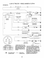
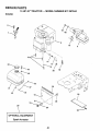
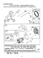
MODEL NUMBER 917.257644
OWNER'S
_ne
• Assembly
= Operation
• Customer Responsibilities
= Service and Adjustments
• Repair Parts
CAUTION:
Read and follow
all safety
rules
TM
Convetr'tlble
and instructions
I IIIIIIII
IIIIII
IIIIIIIII
MANUAL
IIIIIII
IIII
before
operating
this
equipment.
IIII
IP
SAFETY
Practices RULES
for Ride-On
Safe Operation
Mowers
IMPORTANT:
THIS CUTTING MACHINE IS CAPABLE OF AMPUTATtNG
HANDS AND FEETAND THROWING
FAILURE TO OBSERVE THE FOLLOWING
SAFETY INSTRUCTIONS
COULD RESULT IN SERIOUS INJURY
I.
GENERAL
•
Read, understand, and foi!ow all instructions in the manual
and on the machine before starting.
Only allow responslbie adults, who are familiar with the
instructions, to operate the machine.
Clear the area of objects such as rocks, toys, wire, etc.,
which could be picked up and thrown by the blade,
Be sure the area isclear of other peopte before mowing. Stop
machine if anyone enters the area,
Never carry passengers.
De not mow in reverse unless absolutely necessary. AIways
look down and behind before and while backing.
Be aware of the mower discharge direction and do not point
it at anyone. Do not operate the mower without either the
entire grass catcher or the guard in place.
Slow down before turning.
Never leave a running machine unattended. Always turn off
b_ades, set parking brake, stop engine, and _emove keys
before dismounting.
Turn off btades when not mowing.
Stop engine before removing grass catcher or unclogging
chute..,
•
•
•
•
•
=
•
•
°
•
•
,
,
•
it.
OPERATION
I!1. CHILDREN
Tragic accidents can occur if the operator is not alert to the
presence of children. Children are often attracted to the machine
and the mowing activity. Neverassume that children will remain
where you last saw them.
*
•
Before and when backing, look behind and down for small
children.
•
Never carry children. They may fall eft and be ssdously
injured or interfere with safe machine operation.
Never allow children to operate the machine.
Use extra care when approaching blind comers, shrubs,
trees, or other objects that may obscure vision.
•
°
iV.
SERVICE
•
Use extra care in handling gasotine and other fuels. They are
flammable and vapors are explosive.
•
°
SLOPE
•
OPERATION
Slopes are a major factor retated to loss-of-control and tipover
accidents, which can resutt in severe injury or death. All slopes
require extra caution. !f you cannot back up the slope or if you feel
uneasy on it, do not mow it.
•
DO:
•
Mow up and down stopes, not across.
Remove'. _bstac_es such as rocks, tree timbs, etc.
,
Watch for hotes, ruts, or bumps.
Uneven terrain could
overturn the machine. Tatl grass can hide obstacles.
Use slow speed. Choose a low gear so that you will not have
to stop or shift while on the stope.
Foilow the manufacturer's
recommendations
for wheel
weights or counterweights to improve stability.
Use extra care with grass catchers or other attachments.
These can change the stability of the machine.
Keep all movement on the slopes slow and gradual Do not
make sudden changes in speed Jr direction.
Avoid starting or stopping on a slope. If tires lose traction,
disengage the btades an_ proceed siowty straigt_t down the
slope.
•
•
•
•
•
Keep children out of the mowing area and under the watchful
care of another responsible adult.
Be alert and turn machine off if children enter the area.
°
Mow only in daytight or good artificial light.
Do not operate the machine while under the influence of
alcohol or drugs.
Watch for traffic when operating near or crossing roadways.
Use extra care when {ceding or unloading the machine into
a trailer or truck.
•
•
•
•
o
-
Use only an approved container.
Never remove gas cap or_ add fuel with the engine
running. Atlow engme to cool before refueling. Do not
smoke,
Never refuel the machine indoors.
Never store the machine or fuel container inside where
there is an open flame, such as a water heater.
Never run a machine inside a closed area.
Keep nuts and bolts, especially btade attachment botts, tight
and keep equipment {n good condition.
Never tamper with safety devices.
Check their proper
operation regularly.
Keep machine free of grass, Ieaves, or other debds build-up.
C{ean oil or fuel spillage.
Allow machine to coot before
stonng.
Stop and inspect the equipment ;f you stdke an object.
Repair, if necessary, before restarting.
Never make adiustments or repairs with the engine runnin_
Grass catcher components are subject to wear, damage, and
deterioration, which coutd expose moving parts or allow
objects to be thrown. Frequently check components and
reptace with manufacturer's recommended parts, when necessary.
Mower blades are sharp and can cut. Wrap the blade(s) Jr
wear gtoves, and use extra caution when servicing them.
Check brake operation frequently. Adjust and service as
required.
Look for this symbol to point out important
safety
precautions,
It means
CAUTION!!!
BECOME ALERT!!!
YOUR
Ul
SAFETY IS INVOLVED.ii
DO NOT:
°
•
•
°
,
ii ii
Do not turn on slopes unless necessary, and then, turn slowly
and gradually downhill, if possible.
Do not mow near drop-offs, ditches, or embankments. The
mower could suddenly turn over if a wheat is over the edge
of a ctiff or ditch, or if an edge caves in.
Do net mow on wet grass. Reduced traction could cause
sliding.
De not try to stabilize the machine by putting your foot on the
ground.
Do not use grass catcher on steep slopes.
OBJECTS.
OR DEATH.
&
i
H
,,,,,,,,
,,,,,,,,,,,,,,,,,,,
i
CAUTION:
Always
disconnect
spark
plug wire and place wire where it cannot
contact spark plug in order to prevent
accidental
starting
when setting
up,
transporting,
adjusting
or making
repairs.
i
2
i
i
J
i
PRODUCT
CONGRATULATIONS
on your purchase of a Sears
Tractor. It has been designed, engineered and manufactured to give you the best possible dependability and
performance.
Should you experience any problem you cannot easily
remedy, please contact your nearest Sears Authorized
Service Center/Department.
We have competent, welltrained technicians and the proper tools to service or repair
this unit.
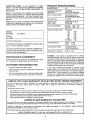
MODEL
NUMBER
HORSEPOWER:
15.0
GASOLINE CAPACITY
AND TYPE:
5 QUARTS
UNLEADED
,,,
Please read and retain this manual. The instructions will
enable you to assemble and maintain your unit properly.
Always observe the "SAFETY RULES".
SPECIFICATIONS
,,,, ,,,
OIL TYPE (API*SF!SG):
SAE 30 (above 32°F)
SAE 5W-30 (below 32°F)
0iL, CAPACITY:
3.0 PINTS
i SPARK PLUG:
CHAMPION
i (GAP: .0,30")
STD361458
VALVE CLEARANCE:
INTAKE:
EXHAUST:
GROUND SPEED (MPH):
FORWARD:
1st
2rid
3rd
4th
5th
6th
REVERSE:
917.257644
SERIAL
NUMBER
OATEOFPURCHASE
THE
MOOELANO
SER ALNUMBERS
W LLBE
FouND
ON
A
PLATE
UNDER
THE SEAT.
YousHouLD
RECORD
BOTH
SERIAL
NUMBER
ANO
0ATE
OFPURCHASE
AND
KEEP
ZN
ASAFE
P CE
IFOR
FUTURE
REFERENCE.
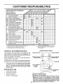
MAINTENANCE
CUSTOMER
is available on this prodstore for details.
RESPONSIBILITIES
•
Read and observe
-
Follow a regular schedule
using your unit.
•
Follow the instructions
under "Customer
Responsibilities" and "Storage" sections of this owner's manual.
............
,, ......
LIMITED
,,
the safety
rules.
in maintaining,
....,,,,
iii1,11111
i i
i
iii
TWO YEAR WARRANTY
.005 ° - _007"
.009" - .01 t"
1.02
t .35
2.t0
3.14
4.00
5.12
1.58
TIRE PRESSURE:
FRONT:
REAR:
14 PSI
12 PSI
CHARGING SYSTEM:
3 AMPS BATTERY
5 AMPS HEADLIGHTS
BLADE BOLTTORGUE:
30-35 FT. LBS.
In the state of California the above is required by Iaw
(Section 4442 of the California Public Resources Code).
Other states may have similar laws. Federal laws apply on
federal lands. A spark arrester for the muffler is available
through your nearest Sears Authorized Service Center/
Department (See REPA!R PARTS section of this manual),
caring for and
,,i,i
RJ-19LM
WARNING:
This tractor is equipped with an internal
combustion engine and should not be used on or near any
unimproved forest-covered, brush-covered or grass*covered land untess the engine's exhaust system is equipped
with a spark arrestor meeting applicable local or state laws
(if any). tf a spark arrester is used, it shoutd be maintained
in effective working order by the operator.
AGREEMENT
A Sears Maintenance
Agreement
uct. Contact your nearest Sears
REGULAR
,
,IHI
I
IIIIIIIIIIIIII
II
ON ELECTRIC
START RIDING EQUIPMENT
For two (2) years from the date of purchase, if this riding equipment is maintained, lubricated and tuned up according to the
instructions in the owner's manua|, Sears will repair or replace, free of charge, any parts found to be defective in matedal or
wo rkmanship.
This Warranty does not cover.
•
•
•
Expendable items which become worn during normal use, such as blades, spark ptugs, air cleaners and belts.
Tire replacement or repair caused by punctures from outside objects, such as nails, thorns, stumps, or glass.
Repairs necessary because of operator abuse, negligence, improper storage or accident or the faiiure to maintain the
equipment according to the instructions contained in the owner's manual.
Riding equipment used for commercial or rental purposes.
°
LIMITED
90 DAY WARRANTY
ON BATTERY
For ninety (90) days from date of purchase, if any battery included with this dding equipment proves defective in material or
workmanship and our testing determines the battery will not hoid a charge, Sears will replace the battery at no charge.
WARRANTY SERVICE
CENTER/DEPARTMENT
IS AVAILABLE BY RETURNING
IN THE UNITED STATES.
THE RIDING EQUIPMENT
TO THE NEAREST
SEARS
This Warranty gives you specific legal dghts, and you may also have other rights which may vary from state to state.
SEARS,
m,ii
iii
i
ii
ROEBUCK
ii
iiiiiiiii
i
iii
AND CO., Df817 WA, HOFFMAN
iiiii
ii
iii
iiiiiiiiiiiiiiiiiiiiiii
ESTATES,
iii
ILLtNOfS
iii
80179
.........
SERVICE
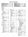
TABLE OF CONTENTS
SAFETY RULES ............................................................
2
PRODUCT SPECIFICATIONS ......................................
3
CUSTOMER RESPONSIBILITIES ..................... 3, 15-19
WARRANTY ..................................................................
3
TABLE OF CONTENTS .................................................
4
INDEX ............................................................................
4
TRACTOR ACCESSORIES ..........................................
5
ASSEMBLY .............................................................
7-10
OPERATION ...................................................
....... 11-14
MAINTENANCE SCHEDULE .....................................
15
SERVICE AND ADJUSTMENTS ........................... 20-25
STORAGE ...................................................................
26
TROUBLESHOOTING ...........................................
27-28
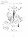
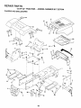
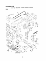
REPAIR PARTS - TRACTOR ................................
30-47
REPAIR PARTS - ENGINE ....................................
48-53
PARTS ORDERING/SERVICE .................. BACK PAGE
INDEX
A
Accessories ............................................
5
Adjustments:
Brake ...........................................
22
Carburetor ...................................
25
Mower:.
Front-To-Back ........................ 21
Side-To-Side .......................... 21
Throttle Control Cable ................. 24
Air Filter, Engine .................................
18
Air Screen, Engine ............................. 18
Assembly .........................................
7-10
B
Battery:
Charging .......................................
Cleaning ......................................
Connecting ....................................
Starting with Weak 8artery .........
Storage .......................................
Terminals ....................................
Botts:
Motion Ddve
Removal/Replacement
...........
Mower Blada Dnve
RemovagRepfacement ...........
B{ade:
Sharpening ..................................
Replacement ...............................
Brake Adjustment ...............................
C
8
17
8
23
26
17
22
22
16
16
22
Carburetor Adjustment ....................... 25
Controls, Tractor ................................
11
Customer Responsibilities ............. l 5-19
Engine:
Air F}lter ...................................
18
Air Screen, Engine .................. t8
Battery .....................................
l7
Cco{ing Fins, Engine ............... 18
Engine Oit ...............................
17
Fuel Filter ................................
19
Spark Plugs ............................. 19
Tractor:.
Blades .....................................
16
Lubrication Chart ..................... 15
Maintenance Schedu|e ........... 15
Tire Care ......................... 9,16,23
Cutting Height, Mower ....................... t2
E
Electrical:
Interlocks and Relays ................. 24
Schematic ...................................
29
Wiring Diagram ........................... 30
Engine:
Air Filter .......................................
18
Air Screen ...................................
18
Cooling Fins, Engine ................... 18
Oi_Change ..................................
!7
Oil Level ................................. 13,17
Oil Type .......................................
17
Preparation ................................. t3
Repair Parts ........................... 48-53
Starting ........................................
14
Storage .......................................
26
O
Oit:
Cold Weather Conditions ....... 13, t7
Engine .........................................
17
Storage .......................................
26
Operation ......................................
11-14
Operating Mower ................................ 13
Options:
Accessodes .................................
5
Spark Arrester .......................... 3,49
P
Parking Brake ................................
11-12
Parts Bag .............................................
6
Parts, Replacement/Repair
........... 30-47
Product Specifications ...... ._................... 3
R
F
Filters:
RepairParts i_..][.
...............
.i
..........
30-47
Air................................................
18
S
Fuel .............................................
tg
Safety Rules .........................................
2
Fuei:
Beat ...........................................
8
Type ............................................
13
Serviceand Adlustments ..............
20-25
Storage .......................................
26
Brake ......................................
22
Fuse ...................................................
24
Carburetor..................................
25
G
Fuse ......................................
2€
Gauge Wheels ..................................... g
Hood Removal/Installation
.......... 24
H
Motion Dnve Belt
Hood Removal/installation ................. 24
Removal/Replacement
........... 22
Mower Blade O,dva Be_!
L
Removal/Replacement
........... 22
Leveling Mower Deck ......................... 21
Mower Adiustment:
Lubdcation Chart ................................
15
Front-!o-Back ......................... 21
M
Side-to-Side ........................... 2I
Maintenance Schedute ...................... 15
Mower Installation ....................... 20
Mower:.
Mower Removal .......................... 20
Adjustment, Front-to-Back .......... 2!
T_re Care ............................. g,I 6,23
Adjustment, Side4o-Side ............ 21
Slope Guide Sheet ............................. 55
Blade Sharpening ....................... 16
Spark Plugs ........................................
lg
Blade Replacement ..................... 16
Specifications ...................................
3
Cutting Height ............................. 12
Starting
the
Engine
.......................
13-14
instaliation ................................... 20
Steedng Wheel ................................
7,23
Operation .................................... 13
Stopping the Tractor ........................... t2
Removal ......................................
20
Storage ........................................
25
Mowing Tips .......................................
14
T
Muffler................................................
I9
Throttle
Contrei
Cable
Adjuetment ..... 24
Spark Arrestor .......................... 3,40
Tires ...........................................
9,16,23
Mulcher Plate.....................................
I0
Trouble Shooting Chart .................. 27-28
Transaxle Repair Parts .................
46.47
W
Warranty ...............................................
;3
Wiring Diagram .................................
30
Wiring Schematic ...............................
29
4
ACCESSORIES
,,,H
................
,
i=
AND ATTACHMENTS
=
_
,,n
..............
,,n
u,,,,n
=,
._u _ul
These accessories and attachments were available through most Sears retail cutters and service centers when the tractor was purchased.
Most Sears stores can order these items for you when you provide the model number of your tractor.
ENGINE
SPARK PLUG
MAINTENANCE
GAS CAN
ENGINE OIL
FUEL
STAB UZER BLADES
BELTS
PERFORMANCE
Sears offers a wide variety of attachments that fit your tractor.
you. This list was current at the time of publication; however,
may be made in these attachments, or some may no longer
accessories and attachments that ate available for your
Most of these attachments de not require additional hitches
attaching and detaching.
Many of these are Jlsted beiew with brief explanations of how they can help
it may change in future years - more attachments may be added, changes
be avai]abte or fit your model. Contact your nearest Sears store for the
tractor.
or conversion kits (those that do are indicated) and _,re dcsignc_ for easy
AERATOR promotes deep root growth for a healthy fawn. To*
pered 2.5-inch steel spikes mounted on 10-inch diameter discs
puncture holes in soil at close _ntervals to let moisture soak iq.
Steet weight tray for increased penetration.
BAGGER lets you collect
grass ctippings and leaves for a
healthier, nearer looking lawn. Two Permanex containers hold
30-gallon plastic bags.
BUMPER protects front end of tractor from damage.
CARTS make hauting easy. Variety of sizes available, ptus
accessories such as side panel kits, toot caddy, cart cover,
protective mat and doily.
CORING AERATOR takes smatl plugs out of soil to allow moisture and nutrients to reach grass roots. 36-inch swath, 24
hardened steel codng tips. 150 lb. capacity weight tray.
EASY OIL DRAIN VALVE makes ell changes easier, faster.
FRONT NOSE ROLLER canters infront of mower deck to reduce
chances of =scalping" on uneven terrain.
GANG HITCH lets you tow 2 or 3 pull-behind attachments at once,
such as sweepers, dethatchers; aerators (not for use with rollers,
carts or other heavy attachments).
GAUGE WHEELS on both sides of the mower deck reduce
chances of "scalping" on uneven terrain. For mower decks not so
equipped.
MULCH RAKF_JDETHATCHER Ioosens soil and ftips thatch and
matted leaves to lawn surface for easy pickup. Twenty spdng tine
teeth. Useful to prepare bare areas for seeding. Available for front
or rear mounting.
HIGH PERFORMANCE
REEL-ACTION
SPRING TINE DETHATCHER covers 36qnch wide path and
tosses thatch into large hopper. Mounts behind tractor.
MULCHING CLOSE-OUT PLATE KIT, once installed, lets you
mulch, discharge or bag clippings (bagger optional) without
changing blades. For models not equipped as 3-in-t Convertible
mowers.
See "MOWER" in the Repair Parts section of this
manual.
RAMP TOPS AND FEET let you load and unload tractor from a
pickup truck. Use with 2 x 8 or 2 x I0 lumber.
ROLLER for smoother lawn surface.
36-1nch wide, 18qnch
diameterwater-tight
drum holds up to 390 tbs. of weight. Rounded
edges prevent harm to turf. Adjustable scraper automatically
cleans drum.
SNOW BLADE forsnow removal onty, 14-inch high, 42-inch wide
btade clears 38-inch path when angted left or right. Raises, lowers
with side Iever. Adjustable skids; repteceable, reversible scraper
bar. (Use with tire chains and wheet w_,ights and/or rear drawbar
weight.)
SNOWTHROWER has 40-inch swath. Drum-type auger bandies
powdery and wet/heavy snow. Mounts easily with simple pin
arrangement. Discharge chute adjusts from tractor seal 6-inch
diameter spout discharges snow 10 to 50 feet. Lilt controlled at
tractor seat, (Use with chains and wheel weights and/or rear
drawbar weight.)
SPRAYERS use 12-volt OC electric motor that connects to the
tractor battery or other 12.vott source_ Includes booms for
automatic spraying and hand held wand for spot spraying. Wand
has adjustal3te spray pattern. For apptying herbicides, ineecti*
cides, fungicides and Iiquid fertilizers.
SPREADEFUSEEDERS make seeding, fertilizing, and weed FdlF
ing easy. Broadcast spreaders are also useful for granular deicers and sand.
SWEEPERS Iet you collect grass ctippings and leaves.
TILLER has 5 hp engine and 36-inch swath to prepare seed beds,
cultivate and compost garden residue. Tiller has its own buittqn
Iift and depth control system and does NOT require a sleeve hitch.
F_tsany lawn, yard or garden tractor. Simply hook up to the tractor
drawbar and go! Optional
accessories
convert unit for
dethatching, aerating, hiIling...without too{s.
TIRE CHAINS are heavy duty; cicseiy spaced extra-large cross
links give smooth ride, outstanding traction.
TRACTOR CAB has heavy duty vinyl fabric over tubutar steel
frame, ABS piastic top; ctear plastic windshield offers 360 degree
visibility. Hinged metal doom with catch. Keeps operator warm
and dry. Remove vinyl sides and windshields Ior use as sun
protector in summer. Optional accessories
include: tinted/
tempered sotid safety glass windshield with hand operated wiper;,
12-volt amber caution light for mounting on cab top.
VACS for powerful collection of heavy grass ciippingsand leaves.
Optional wand attachment to pick up debris in hard-to-reach
places. VAC/CHIPPER inctudes a chipper-shredder.
WF.JGHT B RACKET for drawbar for snow removal applications.
Uses (1) 55 lb. weight.
WHEEL WEIGHTS for rear wheels provide needed traction for
snow removal or dozing heavy materials.
,,=
,,
,
,,,,n,,, u
...............
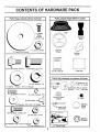
Parts Bag contents
,
shown full size
,, =
, =
,,,,,,,u
Parts packed separately
...............
,
, =
=
Screws
Metal
#10-16 x 1/2
Steering
Boot
(1) Locknut 3/8-24
Steering
Wheel
(1) Large Fiat Washer
u
,, =r
,,
Hi1
(1) Shoulder 8o/t 5116-18
Mulcher
Plate
,,,,,,,, u,
(1) Hex Bolt 1/2-13 x 1
©WHOPSManual
Parts Bag
Parts bag contents
......
_1
(1) Lock Washer
I7/32 x 1-3/16 x 12 Gauge
,,,1n, ,,,,,1
__WS
(2} Shoufder
Botts
\
,
full size
t'_"_
(2) Washers
3/8
(2) Centerlock Nuts
,,,,uu@
#10 X 518
n
not shown
H,, uu
i_._//(2) Gauge _._
"---_
Wheels
_
(2) Lock Washers
#10
Steering Wheet
Adapter
nni
,,,,,,,,,
1/2
i/f-_'_
1) Washer
,nn=
Seat
(2) Sheet
,11
in carton
_
,,, in
(2) L_tch Hook
Assemblys
(2) Keys
Steering
Wheel
insert
(2) Hex 80 ts 1/4-20 × 3/4
Steering
Bushing
(2) Hex Nuts l/4-20
12) Washers
................
9/32 x 5/8 x ! 6 Gauge
(2 ! Loc!{ Washers
I/4
.
!5 °
•
i ,11111
ii
ii
i,illU i i
ii i
,
iiirlii i
i
HllUU III
II1'1'11111'1
III II I
I
I
ASSEMBLY
11111
,Rrlllllll
illUl,ii iiii
iiii
i
,,,
,,,,,,,,,,,,, u
i,i
',Hill
ii
iiii
I
lUl
I
iiiiiiiiiiiii
Your new tractor has been assembled at the factory with exception of those parts left unassembted for shipping purposes.
To ensure safe and proper operation of your tractor all parts and hardware you assemble must be tightened securely. Use
the correct tools as necessary to insure proper tightness.
TOOLS
REQUIRED
FOR ASSEMBLY
A socket wrench set wittmake assembly easier. Standard
wrench sizes are listed.
(1) 5/16" wrench
(!)
3/4" Socket w/dnve rachet
(2) 7/16" wrenches
Phillips Screwdriver
(1) 1/2" wrench
Tire pressure gauge
(1) 9/16" wrench
Utility knife
When right or left hand is mentioned in this manual, it
means when you are in the operating position (seated
behind the steering wheel).
BUSHING
TO REMOVE TRACTOR
UNPACK
FROM CARTON
CARTON
•
Remove all accessible loose parts and parts cartons
from carton (See page 6),
•
Cut, from top to bottom, atong lines on atl four comers
of carton, and lay panels fiat.
°
Check for any additional loose parts or cartons and
remove.
BEFORE ROLLING TRACTOR
ATTACH
SCREW'
STEERING
WHEEL
PosmoN)
OFFSKID
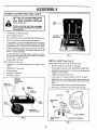
(See Fig, 1)
-
Slide the steering bushing over the steenng shaft.
.
Raise steering shaft forward until screw holes in dash
line up with steering bushing.
Install two (2) sheet
metal screws and tighten securely.
•
Posit{on steering boot over steering shaft.
•
Ptace tabs of steering boot over tab slots in dash and
push down to secure,
•
Slide steering wheel adapter onto upper steedng shaft.
,
Position front wheels of the tractor so they are pointing
straight forward.
,
Position steering wheel so cross bars are horizontal
(left to right) and siide onto adapter.
•
Assemble large flat washer and 3/8-24 iocknut and
tighten securely.
•
Snap steering wheel insert into center of steering
wheel.
•
Remove prote_ive ptast_c from tractor hood and grill.
IMPORTANT:CHECK FOR AND REMOVE ANY STAPLES
IN SKID THAT MAY PUNCTURE TIRES WHERE TRACTOR
tS TO ROLL OFF SKID.
SLOT
F]G. t
TO ROLL
TRACTOR
OFF SKID (See Fig. 8)
Raise attachment lift tever to its highest position.
•
•
•
•
Release parking brake by depressing clutch/brake
pedal.
Place gearshift lever in neutral (N) position.
Rotl tractor backwards off skid,
Remove banding holding discharge guard up against
tractor.
ASSEMBLY
HH,= ='===========
= == n
CONNECT
BATTERY
=
(See Figs. 2 and 3)
CAUTION: Do not short battery terminals. Before connecting battery, remove metal bracelets,
wristwatch
bands, rings, etc.
SEAT
PAN
Positive terminal must be connected
first to prevent sparking from accidental grounding.
,,n,
i
in=
•
Lift seat pan to raised position.
•
Open battery box door.
o
°
Be sure battery drain tube is attached to battery box.
Remove terminal protective caps and discard.
-
If this battery is put into service after month and year
indicated on labet (label tocated between terminals)
charge battery for minimum of one hour at 6-10 amps.
-
First connect RED battery cable to positive (+) terminal
with hex bolt, flat washer, lock washer and hex nut as
shown. Tighten securely.
•
Connect BLACK grounding cable to negative (-) terminalwith remaining hex bolt, flat washer, lock washer
and hex nut. Tighten securely.
°
Ctose battery box door.
lnspectien
FIG. 3
INSTALL
Open battery box door for:
•
BOX DOOR
for secure connections
(to tighten hard-
SEAT (See Fig. 4)
Adjust seat before tightening adjustment bolt.
ware).
°
Remove cardboard packing on seat pan.
-
Inspection for corrosion.
=
PIace seat on seat pan and assemble shoulder boff,.
•
Testing battery.
=
o
Jumping ({f required).
Assemble adiustment bolt, lock washer and flat washer
Ioosety. Do not tighten.
,
Periodic charging.
.
Tighten shoulder bolt securely.
-
Lower seat into operating position and sit on seat.
•
Slide seat until a comfortable position is reached which
allows you to press dutch/brake pedal all the way
down.
°
Get off seat without moving its adjusted position.
°
Raise seat and tighten adjustment bolt securely.
DISCARD
• TERMINAL
PROTECTIVE
CAPS
(RED) CABLE
POSITIVE
t
HEX
NUT
LOCK
WASHER
FLAT
WASHER
\
SHOULDER
BOLT
VENT
BOLT
SEAT PAN
SEAT_
NEGATIVE
(BLACI_ CABLE
_
RG. 2
ADJUSTMENT
BOLT
LOCK WASHER
LARGE FLAT WASHER
F{G. 4
iiii
ii ,llllllll
.........,.,,,,,,,,,,,,,,,,,,,,,,,,
illli
i
"
i
i
, ....
ASSEMBLY
ill
CHECK
,1111_1
i
iiii
¸ i
i
i
iii
TIRE PRESSURE
The tires on your tractor were ovefinflated at the factory for
shipping purposes. Correct tire pressure is important for
best cutting performance.
•
DECK LEVELNESS
FOR
PROPER
POSITION
OF
ALL
See the figures that are shown for replacing motion and
mower blade ddve belts in the Service and Adjustments
section of this manual
Verify that the belts are routed
correctly.
CHECK
BRAKE
i
i
iiiiiiiii
WHEELS
iii
TO
iiiiii
MOWER
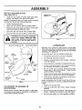
•
Adjust mower to desired cutting height (See "TO ADJUST MOWER CUTTING HEIGHT"in the Opera,on
section of this manual).
•
With mower in desired height of cut position, gauge
wheels should be assembled so they are slightlyoff the
ground, install gauge wheel in appropriate hole with
shoulder bolt, 3/8" washer and 3/8-16 locknut and
tighten securely.
•
Repeat for opposite side insta!ling gauge wheel in
same adjustment hole.
For best cutting results, mower housing should be properly
leveled. See "TO LEVEL MOWER HOUSING" in the
Service and Adjustments section of this manual.
CHECK
BELTS
iiii
Assemble gauge wheets with tractor on a flat level surface.
Reduce tire pressure to PSi shown in "PRODUCT
SPECIFICATIONS
on page 3 of this manual.
CHECK
i
ASSEMBLE
GAUGE
DECK (See Fig. 5)
GAUGE WHEEL
MOUNTING
BRACKET
t
'_.,
SYSTEM
After you learn how to operate your tractor, check to see
that the brake is property adjusted.
See "TO ADJUST
BRAKE" in the Service and Adjustments section of this
manual.
SHOULDER
FIG. 5
BOLT
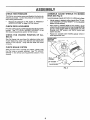
INSTALL MULCHER
(See Figs. 6 & 7)
*
PLATE
DEFLECTOR
Install two tatch hooks to mulcher plate using screw,
washer, lock washer, and weld nut as shown.
NOTE: Pre-assemble weld nut to latch hook by inserting
weld nut from the top with hook pointing down.
o
Tighten hardware securely.
.
Raise and hold deflector shield in upright position.
=
°
Place front of mulcher plate over front of mower deck
opening and s_ide into place, as shown.
Hook front latch into ho_e on front of mower deck.
*
Hook rear latch into hole on back of mower deck.
= = 11,11
=
i
=
LATCH
HOOKS
ill=
guard from mower. Raise and hold
guard when Doattaching
CAUTION:
not remove
mulcher
discharge
plate
and allow it to rest on plate while in
operation.
t_
,,,,,=,=, ,,
FTG. 7
,,,
WELD NUT FROM THE TOP
,/CHECKLIST
HOOK POINTS DOWN
BEFORE YOU OPERATE AND ENJOY YOUR NEW
TRACTOR, WE WISH TO ASSURE THAT YOU RECEIVE
THE BEST PERFORMANCE AND SA TISFA CTION FROM
THIS QUALITY PRODUCT.
WELD
NUT
PLEASE REVIEW THE FOLLOWING
LOCK
WASHER
SCREW
CHECKLIST:
•/
All assembly instructions have been completed.
,/
No remaining loose parts in carton.
J
Battery is properly prepared and charged.
! hour at 6 amps).
LATCH
(Minimum
,," Seat is adiusted comfortably and tightened securely.
,/
AII tires are properly inflated. (For shipping purposes,
the tires were ovednflated at the factory).
.J
i3e sure mower deck is proper!y reveled side-to-side/
front-to-rear for best curing results. (Tires must be
properly inflated for leveling).
Check mower and drive belts. E]e sure they are routed
properly around pulleys and inside all be_t keepers.
LOCK
WASHER
WASHER
/
WASHER
/
MULCHER
PLATE
_._
SCREW
WHILE LEARNfNG HOW TO USE YOUR TRACTOR, PAY
EXTRA A TTENTION TO THE FOLLOWING tMPORTA,Nq"
ITEMS:
FIG. 6
TO CONVERT
DISCHARGING
TO BAGGING
Check wiring. See that all connections are still secure
and wires are property cJamped.
OR
Simply remove mutcher ptate and store in a safe place.
Your mower is now ready for clischarging or installation of
optional grass catcher accessory.
,/
Engine oil is at proper tevet.
/
Fuel tank is filled with fresh, clean, regutar unleaded
gasoline.
Become familiar with atl controls - their tocation and
function. Operate them before you start the engine.
/
/
10
Be sure brake system is in safe operating
condition.
ii
iiiiiii
i
,11
iii
ii r
i
iiiir
......
i
i
i
ii
OPERATION
ml
iii
i
L
i
nll,i ii
.
ii
im..iMi
•
KNOW YOUR TRACTOR
READ THIS OWNER'S
MANUAL
AND SAFETY
RULES
BEFORE
OPERATING
YOUR
TRACTOR
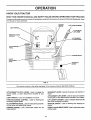
Compare the illustrations with your tractorto familiarize yourseff with the locations of vadous controls and adjustments, Save
this manual for future reference.
IGNITION
SW1TCH
LIFT LEVERPLUNGER
ATTACHMENT
LIFT LEVER
THROTTLE/CHOKE
CONTROL
ATTACHMENT
.UTCHLEVER
CLUTCH/BRAKE
PEDAL
PARY*JNG BRAKE
HEIGHT
ADJUSTMENT
KNOB
GEARSHIFT
L_"VER
FIG. 8
Our tractors conform to the safety standards of the American NationaJ Standards Institute,
GEARSHIFT LEVER: Selects the speed and direction of
tractor.
ATTACHMENT CLUTCH LEVER: Used to engage the
mower blades, or other attachments mounted to your
tractor.
LIGHT SWTTCH: rums
ATTACHMENT LiFT LEVER: Used to raise and lower_e
mower deck or other attachments mounted to your tractor.
the headlights on and off.
THROTFLFJCHOKE
CONTROL:
controlling engine speed.
LIFT LEVER PLUNGER: Used to release attachment lift
lever when changing its position.
Used for starting and
CLUTCH/BRAKE PEDAL: Used fordectutchingandbraking the tractor and starting the engine.
IGNITION SWITCH:
engine.
PARKING BRAKE:
brake position.
HEIGHTADJUSTMENT
cutting height.
Locks clutch/brake
pedal into the
11
Used for starting and stopping the
KNOB: Usedto adjustthe mower
,u
,11
i,
,,,,,,11
i,
_
_
i
i
i
,lUl,,ll,
Tit
i
iiiii
iiiii
,
,
,
i,iii
OPERATION
,llll
i
i,,m
,...................
mill
,, ,
i,iiii iiiiiii i
,1,1,
,u
HIIIII
.,,,,,,,,,,,,,.,,,,,,,,,,,,,11111
i iiiii
iii
IIHII i
, ,
,u
Ul
,11
i,iii
ii
i iii
i
i
=l i
i i
i ,
ii
iii
iii
iii
]
,
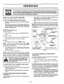
The operation of any tractor can result in foreign objects thrown into the eyes, which can
result in severe eye damage. Always wear safety glasses or eye shields while operating your
tractor or performing any adjustments or repairs. We recommend a wide vision safety mask
for over the spectacles or standard safety glasses.
HOW TO USE YOUR TRACTOR
TO
SET
PARKING
BRAKE
(See Fig. 9)
•
Depress c{utchibrake pedal into full =BRAKE" position
and hold.
•
Place parking brake lever in "ENGAGED" position and
release pressure from ctutchJbrake pedal. Pedal should
remain in "BRAKE" position. Make sure parking brake
witl hold vehicle secure.
STOPPING
GROUND
•
•
Move gearshift and range shift levers to desired position.
Slowly release clutch!brake pedal to start movement
IMPORTANT: BRING TRACTOR TO A COMPLETE STOP
BEFORE SHIFTING OR CHANG{NG GEARS. FAILURE
TO DO SO WILL SHORTEN THE USEFUL LIFE OF YOUR
TRANSAXLE.
(See Fig. 9)
PARKING
"BRAKE"
POSITION
Depress clutch/brake pedal into full "BRAKE" posKion.
•
ATTACHMENT CLUTCH
"ENGAGED"
POSITION
lever to neutral (N) position.
Move throttle control to slow (-,lib)
position.
•
Turn ignition key to "OFF' position and remove key,
Always remove key when leaving tractor to prevent
unauthorized use.
-
Never use choke to stop engine,
CLUTCH/BRAKE
PEDAL
"DRIVE" POSITION
H
i
, m,IHIIIII
Ilml,,,,ll,
TO ADJUST MOWER
(See Fig. 9)
i
ii umH
ii
TO USE THROTTLE
......... .,,,,
•
Operating engine at less than full throttle reduces the
battery charging rate.
•
Futl throttle offers the best bagging and mower performance.
FORWARD
AND
HEIGHT
Turn knob clockwise (f'-'_l) to raise cutting height.
°
Turn knob counterclockwise
height.
()f"_)
to lower cutting
•
The average lawn should be cutto approximately 2-I/2
inches during the cool season and to over 3 inches
during hot months. For healthier and better looking
lawns, mow often and after moderate growth.
•
For best cutting performance, grass over 8 inches in
height should be mowed twice. Make the first cut
relatively high; the second to desired height.
BACKWARD
(See Fig. 9)
The direction and speed of movement
gearshift lever,
CUTTING
The cutting height range is approximately 1-t/2" to 4". The
heights are measured from the ground to the blade tip with
the engine net running. These heights are approximate
and may vary depending upon soil conditions, height of
grass and types of grass being mowed.
(See Fig. 9)
Always operate engine at full throttle.
TO MOVE
KNOB
•
..........
CONTROL
\
HEIGHT ADJUSTMENT
The cutting height is controlled by turning the height adjustment knob in desired direction.
III
pletely, as described above, before leaving
the operator's
to empty
CAUTION:
Always position;
stop tractor
comgrass catcher, etc.
l&
"DISENGAGED"
POSITION
FIG. 9
NOTE: Under certain conditions when tractor is standing
idle with the engine running, hot engine exhaust gases may
cause "browning" of grass. To eliminate this possibility,
always stop engine when stopping tractor on grass areas.
i,
BRAKE
PosrTION
GEARSHIFT
LEVER
/'_-_.
NOTE:
Failure to move throttle control to slow (,,i@)
position and allowing engine to idle before stopping may
cause engine to "backfire".
iii
LEVER
po-
DRIVE -
°
Move gearshift
ENGINE -
!
|
i
I
I
Start tractor with clutch/brake pedal depressed and
gearshift lever in neutral (N) position.
THROTTLE]
CHOKE
CONTROL
Move attachment clutch lever to "DISENGAGED"
sition.
!
•
MOWER BLADES °
ii
iiiii
is controlled by the
12
i
iu,,,,,,,rll
i
II
i
,
lUlll,llll,
jib,ill
• •. ............... ,
,nnln
,inn
,,,
OPERATION
.
nil
i i
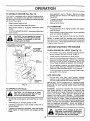
TO OPERATE
., ............. ,,,,,,
MOWER
u
(See
inn
i,,,i
Fig. 10)
Your tractor is equipped with an operator presence sensing switch. Any attempt by the operator to leave the seat
with the engine running and the attachment clutch engaged
witi shut off the engine,
•
°
Select desired height of cut.
Lower mower with attachment lift control.
,
Start mower blades by engaging
control.
•
TO STOP MOWER BLADES - disengage attachment
clutch control.
Ill
attachment
i
.IH
ii
ATTACHMENT CLUTCH LEVER
"DISENGAGED"
POSITION
i.iiinn
111111
nl
I
I =
Move gearshift lever to 1st gear. Be sure you have
allowed room for tractor to roll slightly as you restart
movement.
•
To restart movement, slowly release parking brake and
clutch/brake pedal.
•
Make all turns slowly.
•
Raise attachment lift to highest position with attachment lift control.
•
When pushing or towing your tractor, be sure gearshift
lever is in neutral (N) position.
•
Do not push or tow tractor at more than five (5) MPH.
NOTE: To protect hood from damage when transporting
your tractor on a truck or a trailer, be sure hood is closed and
secured to tractor. Use an appropriate means of tyinghood
to tractor (rope, cord, etc.).
nl
BEFORE
*ENGAGED"
POSITION
irllll
TO TRANSPORT
clutch
CAUTION: Do not operate the mower
without either the entire grass catcher,
on mowers so equipped, or the discharge guard in place.
ii u
i
•
nl
&
,i,u,,,in
ATTACHMENT
LEVER
HIGH POSt33ON
CHECK
STARTING
ENGINE
THE ENGINE
OIL LEVEL (See Fig. 15)
o
The engine in your tractor has been shipped, from the
factory, already filled with summer weight oi!.
•
•
Check engine oil with tractor on level ground.
Remove oil fill capfdipstick and wipe clean, reinsert the
dipsticJ< and screw cap tight, wait for a few seconds,
remove and read oil level If necessary, add oil until
"FULL" mark on dipstick is reached. Do not overfill.
•
For cold weather operation you should change oil for
easier starting (See "OIL VISCOSITY CHART" in the
Customer Responsibilities section of this manual).
•
To change engine oil, see the Customer Responsibilities section in this manual,
ADD GASOLINE
•
Fill fuel tank. Use fresh, ctean, regular unleaded
gasoline. (Use of leaded gasoline will increase carbon
and lead oxide deposits and reduce valve life).
IMPORTANT: WHEN OPERATING rN TEMPERATURES
BELOW 32°F(0°C), USE FRESH, CLEAN WINTER GRADE
GASOLINE TO HELP INSURE GOOD COLD WEATHER
STARTING,
DISCHARGE
GUARD
RG. 10
TO OPERATE
ON HILLS
"_::-_
i,iii
I
_
! _
I U
i ,,,,i,iiin
,i,nn
i
i
ii
i
WARNING:
Experience indicates that alcohol b{ended
fuels (catled gasohot or using ethanol or methanol) can
attract moisture which Ieads to separation and formation of
acids during storage. Acidic gas can damage the fuel
system of an engine while in storage. To avoid engine
problems, the fuel system should be emptied before storage of 30 days or longer. Drain the gas tank, start the
engine and let it run until the fuel }ines and carburetor are
empty. Use fresh fuel next season. See Storage instructions for additional information.
Never use engine or
carburetor cJeaner products in the fuet tank or permanent
damage may occur.
iii
CAUTION:
Do not drive up or down
hills with slopes greater than 15° and
do not clrive across any slope.
_J
iiiiii
ii, ,i
i
,
inl I
i
•
Choose the slowest speed before starting up or down
hills.
•
Avoid stopping or changing speed on hills.
•
If slowing is necessary, move throttle control Iever to
s_ower position.
•
If stopping is absolutely necessary, push clutch/brake
pedal quickly to brake position and engage parking
brake.
I _BIL
I O
i^
13
filler neck. Do not overfiii. Wipeoffany
spilled oil or fuel Do not store, spill or
gasoline near an open flame.
o.oJo,o
.o.=. I
TO START
ENGINE
(See Fig. 9)
•
When starting engine for the first time or if engine has run
out of fuel, it wi}l take extra cranking time to move fuel from
the tank to the engine,
•
Depress clutch/brake
•
Place gearshift lever in neutral (N) position.
°
Move attachment clutch to "DISENGAGED"
•
Move throttle control lever to choke (rxI) position for
cold engine start. For warm engine start, move throttle
control to fast (,,t_) position.
pedal and set parking brake.
position,
•
Insert key into ignition and turn key clockwiseto"STAR'F'
position and release key as soon as engine starts. Do
not run starter continuously for more than fifteen
seconds per minute. If engine does not start after
several attempts, move throttle control to fast (,f_)
position, waft a few minutes and try again.
.
When engine starts, move throttle control to desired
position.
•
Allow engine to warm up for a few minutes before
engaging drive or attachments.
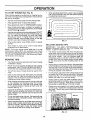
FIG. 11
MULCHING
MOWING
TIPS
IMPORTANT:
FOR BEST PERFORMANCE,
KEEP
MOWER HOUSING FREE OF BUILT-UP GRASS AND
TRASH. CLEAN AFTER EACH USE.
NOTE: If at a high altitude (above 3000 feet) or in cold
temperatures (below 32_F), the carburetor fuel mixture
may need to be adjusted forbest engine performance. See
"70 ADJUST CARBURETOR" in the Service and Adjustments section of this manual.
MOWING
When operating attachments, select a ground speed
that wilt suit the terrain and give best performance of
the attachment being used.
-
The special mulching blade will recut the grass dippings many times and reduce them in size so that as
they fail onto the lawn they wiiI disperse into the grass
and not be noticed. Also, the mulched grass will
biodegrade quickly to provide nutrients for the lawn.
Always mulch with your highest engine (blade) speed
as this will provide the best recutting action of the
blades,
•
Avoid cutting your Iawn when it is wet. Wet grass tends
to form clumps and interferes with the mulching action.
The best time to mow your lawn is the early afternoon.
At this time the grass has dried and the newly cut area
wilt not be exposed to the direct sun.
TIPS
•
Tire chains cannot be used when the mower housing
is attached to tractor.
•
Mower should be properly leveled for best mowing
performance. See "TO LEVEL MOWER HOUSING" in
the Service and Adjustments section of this manual.
=
The left hand side of mower should be used for trimming.
o
•
Drive so that ctippir_gs are discharged onto the area
that has been cut. Have the cut area to the right of the
machine. This will result in a more even distribution of
clippings and more uniform cutting.
For best results, adjust the mower cutting height so that
the mower cuts off only the top one4hird of the grass
blades (See Fig. 12). For extremely heavy mulching,
reduce your width of cui and mow slowly.
•
,
When mowing large areas, start by turning to the right
so that clippings wilt discharge away from shrubs,
fences, driveways, etc. After one ortwo rounds, mow
in the opposite direction making left hand turns until
finished (See Fig. 11 ).
Certain types of grass and grass conditions may require that an area be mulched a second time to completely hide the clippings. When doing a second cut,
mow across or perpendicular to the first cut path.
•
Change your cutting pattern from week to week, Mow
north to south one week then change to east to west the
next week. This will help prevent matting and graining
of the lawn.
•
If grass is extremely tall, it should be mowed twice to
reduce Ioad and possibte fire hazard from dried clippings. Make first cut relatively high; the second to the
desired height.
•
Do not mow grass when it is wet. Wet grass will plug
mower and leave undesirable clumps. Allow grass to
dry before mowing.
°
Always operate engine at full throttle when mowing to
assure better mowing performance and proper discharge of material Regulate ground speed by selecting a low enough gear to give the mower cutting
performance as well as the quality of cut desired.
F1G. 12
14
,,,ll
ilu
,,ill
i,lu
i
i¸ i
i
unnll
j
i
n
CUSTOMER
.............
Ill
MAINTENANCE
nil°'
II
ii
T
Check
Brake
Tire Pressure
i,
...........,,,,
,,,,,,,
I
I
II
J
Check
Battery
0
CIean
Batteq_' and Terminals
R
JCheck TranSaxie
Inspect
I
N
Drive Belt(s)
..........
_-
,
......
Tension
Air Filter Paper
Fuel Fitter
more
often when
more
often
w_en
w*th oil
filter,
GENERAL
mere
''[
If
IIIIIIII
----
I
.........................
' "
i i....'ii'
_,,
J
I_2
I
if
cttetlge
often when
v'[v'
I...........
!
Cartridge
tn dirty
a heavy
or dusty
oil eve.,y
50 _ours.
mowing
in se_cly
load or in aigh ameient
ternperatunss,
cor'ldit_ons.
soil.
I ....
5 - _fequi#pee _
ediuet_Ote sy_ern.
6 - Not required if equi#ped w_tt_mainterlancs-free
battery.
7 - 3]ghten front a._depivot boft to 35 _4bs. rnax_munl.
Do not ove_i_ten.
LUBRICATION
(_)SP!NOLE
ZERK--_
BEARING ZER_ _
All adjustments in the Service and Adjustments section of
this manual should be checked at least once each season.
(_
)ATTACHMENT"k,.
CLUTCH
EACH USE
Check engine oi! leveI.
-
Check brake operation.
•
Check tire pressure.
Check for Ieose fasteners.
CHART
t..._q
® F_ONT
W.E_L_."'_
Once a year you should repiace the spark plug, ctean
or replace air filter, and check blades and belts for
wear. A new spark ptug and clean air filter assure
proper air-fuel mixture and heip your engine run better
and last fonger.
:
vsi
.........
ii[_
RECOMMENDATIONS
•
.....
1
I
'
Operating under
ooerat_ng
"
]
Some adjustments witl need to be made periodically to
properly maintain your tractor.
BEFORE
I
_s
The warranty on this tractor does not cover items that have
been subjected to operator abuse or negligence.
To
receive full vatue from the warranty, operatormustmaintain
tractor as instructed inthis manual.
,
,
if
l/
=
.......
Replace
bia_es
V'
Oit Filter (If equipped)
2 - Service
'11 I1'1
..................
V ....
Arrestor
Repiace
4 - Aepiace
,,,,,,,,,,,,i
)
.......,:
CIeanEng'neO°°HngF'ns
Reptace
Spark Plug
3 - If equipoed
,,,,,,,,,
I_
Oil Level
I . Char_je
i =,rll
DATES
'V',
Cooling
Air Screen
Repiace
illll
_"
LaveVReoharge
Muffler/Spark
llJ,
v' '
Adio°tBla,eBe,t,,)Teo,ion
......
Clean
i
I/,
,,
T
G
Inll
Ii
cA u .oo,,on
o.o.
N
iirlrll i,i ¸
If
CheckfO,LooseFa,tene_
Check" Engine
i
/__;'_';_._'SERV_CE
Operation
Motion
ii
/__o_f
R '"S'hamerVF_eplace
Mower atades
Adjust
iii
__Y
_Eau_R
SERWCB
Check
iiiii
RESPONSIBILITIES
SCHEDULE
FILL IN DATES
AS YOU COMPLETE
illU,lnll
1"--SPINDLE
ZERK (_
............
_"_--_"
_RO_WHEEL
®
2..........
F-'-t
._'
! I
ENGINE (_)
":::::::::=:::'
__
_
_
/
[
........_
___._"_
\
I
i_["_GEARSHIFT
PINTS
(_) SAE 30 OR 10W30 MOTOR OIL
(_) GENERAL
PURPOSE GREASE
(_) REFER TO CUSTOMER
RESPONSIBILITIES
"ENGINE"
SECTION
IMPORTANT:
DO NOT OIL OR GREASE
THE PIVOT POINTS
WHICH HAVE SPECIAL NYLON _EARINGS.
VISCOUS
LUBRICANTS WILL ATTRACT
DUST AND DIRT THAT WILL SHORTEN
THE LIFE OF THE SELF-LUBRICATING
BEARINGS.
IF YOU
FEEL THEY MUST BE LUBRICATED,
USE ONLY A DRY, POW15
OERED
GRAPHITE
TYPE LUBRICANT
SPARINGLY.
iJ,,IVnUl,
IIII
,11111111
,.,
I,
,,,,,,,, ,, ,,,',,,u,
irllnn
CUSTOMER
u_u m
,
i
,,lun
..........
viii
ii1,1111,111111
i.v,,.,
, i
,
,
lUl
RESPONSIBILITIES
I
i i
nnlnl
I
Ill
,
PlIIII,
,llln
I
nlu
,,
n
,
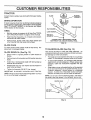
TRACTOR
BLADE
Always observe safety rules when performing any maintenance.
\\
BRAKE
_'_
MANDREL
__
ASSEMBLY
OPERATION
If tractor requires more than six (6) feet stopping distance
at high speed in highest gear, then brake must be adjusted.
(See "TO ADJUST BRAKE" in the Service and Adjustments section of this manual).
TIRES
•
Maintain proper air pressure in all tires (See "PRODUCT SPECIFICATIONS" on page 3 of this manual).
°
Keep tires free of gasoline, oi!, or insect control chemicals which can harm rubber.
•
Avoid stumps, stones, deep ruts, sharp objects and
other hazards that may cause tire damage.
BLADE
FIG. 13
CARE
For best results mower blades must be kept sharp.
place bent or damaged blades,
,_LADE
•AO..D,,.EA..RE..EO
eE
eY.,X.NES
O. °eL.CAN
REMOVAL
Re-
TO SHARPEN
Raise mower to highest position to a{Iow access to
blades.
I
Remove hex bolt, lock washer and fiat washer secudng
biade.
o
Instatl new or resharpened blade with trailing edge up
towards deck as shown.
s
Reassemble hex bolt, lock washer and flat washer in
exact order as shown.
(See Fig. 14)
Care should be taken to keep the blade balar_ced. An
unbalanced blade will cause excessive vibration and eventual damage to mower and engine.
(See Fig, 13)
-
BLADE
•
The blade can be sharpened with a file or on a gdnding
wheel. Oo not attempt to sharpen while on the mower.
*
To check blade balance, you will need a 5/8" diameter
steel bolt, pin, or a cone batanoer. (When using a cone
bafancer, follow the instructions supplied with balarIce 0.
-
•
Tighten bo{t securely (30-35 Ft. Lbs. torque).
IMPORTANT: BLADE £OLT IS GRADE 8 HEATTREATED.
NOTE: We do not recommend sharpening blade- but if you
do, be sure the blade is balanced.
SJide blade on to an unthreaded portion of the steel bolt
or pin and hold the bolt or pin para{leJ with the ground.
;f blade is balanced, it should remain in a horizontal
position. If either end of the blade moves downward,
sharpen the heavy end until the b_ade is balanced.
NOTE: Do not use a nait for balancing blade. The lobes of
the center hote may appear to be centered, but are not.
CENTER HOLE
FIG. 14
16
/
/
,,,,
i ,ml ii, i i
i
i
n
n,
i
u
......................
CUSTOMER
i
i
u
nn
i
nl
i .i, n i Ul
.u,
in
•
Keep battery and terminals dean,
•
Keep battery botts tight,
•
Keep small vent holes open (See "CONNECT BATTERY" in the Assembty section of this manual).
•
Recharge at 6-10 amperes for I hour,
Open battery box door.
Disconnect BLACK batter,/cabie first then RED battery cable and remove battery from tractor.
•
Wash batten! with solution of four tablespoons of
baking soda to one gallon of water. Be careful not to get
the soda solution into the ceils.
•
Rinse the battery with plain water and dry.
•
Clean terminals and battery cable ends with wire brush
until bright.
•
Coat terminals with grease or petroleum ietty.
•
Reinstall battery (See "CONNECT
Assembly section of this manuat).
iiiii i
•
Be sure tractor is on level surface.
•
Oil will drain more freely when warm.
•
Catch oil in a suitable container.
•
Remove oil fill cap/dipstick. Be careful not to allow dirt
to enter the engine when changing oil.
•
•
Remove drain piug.
After oit has drained completely, replace oil drain plug
and tighten securely.
•
Refill engine with oil through oil fill dipstick tube. Pour
slowly. Do not overfill, For approximate capacity see
"PRODUCT SPECIFICATIONS"
on page 3 of this
manual,
•
Usa gauge on oil fill cap/dipstick for checking level. Be
sure dipstick cap is tightened securely for accurate
reading. Keep oil at "FULL" fine on dipstick.
BATTERY" in the
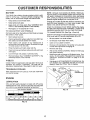
COOLING
Keep transaxie free from build-up of dirt and chaff which
can restrict cooling.
ENGINE
LUBRICATION
Only use high quatity detergent oil rated with APt service
classification SF or SG, Seiect the oil's SAE viscosity grade
according to your expected operating temperature,
0*
-20°
TEMPERATURE
30"
,tO'*'
RANGE
32 _
FIG. 16
GRADES
40*
0_
AN33O=PATED
80=
_0"
BEFORE
20'*
NEXT
30_
OiL
i
Determine temperature range expected before oil change.
All oil must meet API service classification SFor SG.
Check V-belts for deterio ration and wear after 100 hours of
operation and replace if necessary. The botts are not
adjustable, Replace belts if they begin to slip from wear.
_20"
n
TO CHANGE ENGtNE OIL (See Figs. 15 and 16)
V-BELTS
-30"
i
Check the crankcase oil level before starting the engine
and after each eight (8) hours of operation. Tighten oil fitl
cap/dipstick securely each time you check the oil IeveL
Corrosion and dirt on the battery and terminals can cause
the battery to "leak" power.
•
........,,,,,_,,,,,,,,,,,,,,,,,,
Change the oil after the first two hours of operation and
every 25 hours thereafter or at least once a year if the
tractor is not used for 25 hours in one year.
TO CLEAN BATTERY AND TERMINALS
•
ii
NOTE: Although multFviscosity oils (5W30, 10W30 etc.)
improve starting in cold weather, these multi-viscosity oils
will result in increased oil consumption when used above
32°F. Check your engine oil level more frequently to avoid
possible engine damage from running low on oil.
Your tractor has a battery charging system which is sufficient for normal use. However, pedodic charging of the
battery with an automotive charger will extend its life.
SAE VISCOSITY
.
RESPONSIBILITIES
i
BATTERY
TRANSAXLE
u
CHANGE
FIG. 15
17
H •
=
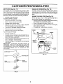
AIR FILTER
=,=
H I,,,,,HHU
, =,,,,H,= =
(See Fig. 17)
CLEAN
Your engine will not run _roperly using a dirty air filter.
Clean the foam pre-cleaner after every 25 hours of operation or ever,/season.
Service paper cartridge every 100
hours of operation or every season, whichever occurs first.
,,,H =
, ,,,=,,,,= ,,,,,,,,
AIR SCREEN
=
==
,=' =
,
i,,i
(See Fig. 18)
Air screen must be kept free of dirt and chaff to prevent
engine damage from overheating. Clean with a wire brush
or compressed air to remove dirt and stubborn dried gum
fibers.
Service air cleaner more often under dusty conditions.
ENGINE
•
Remove knob(s) and cover.
TO SERVICE PRE-CLEANER
COOLING
FINS (See Fig. 18)
Remove any dust, dirt or oil from engine cooling fins to
prevent engine damage from overheating.
•
Slide foam pre-cieaner off cartridge.
•
Wash it in liquid detergent and water.
•
Squeeze it dry in a clean cioth.
•
Cover oil fill opening to prevent entry of dirt.
•
Saturate it in engine oil. Wrap it in ctean, absorbent
cloth and squeeze to remove excess oil.
°
Use compressed air or stiff bristle brush to thoroughly
clean engine cooling fins.
•
If very dirty or damaged, replace pro-cleaner.
•
To reassemble, reverse above procedure.
•
Reinstatl pre-cteaner over cartridge,
Remove screws from blower housing and lift housing
and dipstick tube assembty off engine.
BLOWER
HOUSING
°
Reinstal! cover and secure with knob(s).
TO SERVICE CARTRIDGE
SCREWS
•
Remove cartridge nut.
o
Carefully remove cartridge to prevent debris from on*
tering carburetor.
Clean base carefully to prevent
debris from entering carburetor.
o
Clean cartridge by tapping gently on flat surface. If very
dirty or damaged, replace cartridge.
AIR SCREEN
•
Reinstall cartridge, nut, precteaner, cover and se_:ure
with knob(s).
IMPORTANT:
PETROLEUM SOLVENTS, SUCH AS
KEROSENE, ARE NOT TO 8E USED TO CLEAN THE
CARTRIDGE. THEY MAY CAUSE OETERIORAT1ONOF
THE CARTRIDGE. DO NOT OIL CARTRIDGE. DO NOT
USE PRESSURIZED
AIR TO CLEAN
OR DRY
CARTRIDGE.
COVER
PLUG
KNOB-"-"
ENGINE COOLING
FiNS
r
FIG. 18
COVER
CARTRIDGE
NUT
PAPER
CARTRIDGE
FiG, 17
18
=,H==,
=
i=ll=
M
=
CUSTOMERRESPONSIBILITIES
MUFFLER
CLAMP
Inspect and replace corroded muffler and spark arrester (if
equipped) as it could create a fire hazard and/or damage.
SPARK
PLUGS
Replace spark plugs at the beginning of each mowing
season or after every 100 hours of operation, whichever
occurs first. Spark ptug type and gap setting are shown in
"PRODUCT SPECIFICATIONS" on page 3 of this manual.
IN-LINE
FUEL FILTER
FUEL
FILTER
(See Fig. 19)
F|G. 19
The fuel _ter should be replaced once each season, if fuel
filter becomes clogged, obstructing fuel flow to carburetor,
replacement is required.
CLEANING
•
With engine cool, remove filter and plug fuel fine
sections.
•
•
Place new fuel filter in position in fuel Iine with arrow
pointing towards carburetor.
Clean engine, battery, seat, finish, etc. of all foreign
matter.
o
•
Be sure there are no fuel tine leaks and clamps are
propedy positioned.
Keep finished surfaces and wheels free of sit gasoiine,
oil, etc.
•
Protect painted surfaces with automotive
'_
Immediately wipe up any spilled gasoline.
type wax.
We do not recommend using a garden hose to ctean your
tractor unless the eJectdcal system, muffler, air filter and
carburetor are covered to keep water out. Water in engine
can result in a shortened engine life.
19
, i.i
i.
.
i
,._rl.
i.-i
i
ii.,.
I
n
JI
=¸1==
.i
ii
Hn
SERVICE AND ADJUSTMENTS
_.tUUl i i
H
HI
ii
nl
_
n ..uH
i
i i
CAUTION:
•
o
•
•
,
,H,
i
i
i
iiii
Hpl
.umn
.,....J,l..,m
nUl
i
n
BEFORE PERFORMING
. ii
,,,,,,,11
ii
i
Ul
ii
H,I,Hn
..n.
I I
I
.......
ANY SERVICE OR ADJUSTMENTS:
Depress clutch/brake pedal fully and set parking brake.
Place gearshift lever in neutral (N) position.
Place attachment clutch in "DISENGAGED" position.
Turn ignition key "OFF" and remove key.
Make sure the blades and all moving parts have completely stopped.
Disconnect spark plug wire from spark plug and place wire where it cannot come in contact with
plug.
.i
n
i
1.1.1,
.
i
ii,
,,...,
,,,,,,,,,,
H.,..,i
TRACTOR
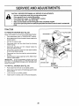
TO REMOVE
MOWER
(See Fig. 20)
CLUTCH
Mower will be easier to remove from the dght side of tractor.
•
•
PIace attachment dutch in "DISENGAGED" position.
Move attachment lift Iever forward to lower mower to its
lowest position.
•
Roll bett off engine puItey.
•
Disconnect clutch rod from clutch lever by removing
retainer spring.
•
Disconnect anti-sway bar from chassis bracket by
removing retainer spring.
•
Disconnect suspension arms from rear deck brackets
by removing retainer springs.
•
Disconnect front links from deck by removing retainer
springs,
•
Raise lift lever to raise suspension arms. Slide mower
out from under tractor.
IMPORTANT;
IF"AN ATTACHMENT OTHER THAN THE
MOWER IS TO BE MOUNTED TO THE TRACTOR, THE
R.H. AND L,H, SUSPENSION ARMS MUST BE REMOVED
FROM TRACTOR.
RETAINER
SPRING
RETAINER
SPRINGS
TO INSTALL
n,,
MOWER
{BOTH SII_ES)
(See Fig. 20)
°
Raise attachment lift lever to its highest position.
,
Slide mower undertractorwfth
side of tractor.
,
°
Lower !ift Iever to its Iowest position.
Install mower in reverse order of removal instructions.
FIG. 20
discharge guard to right
2O
•
,i H nH I¸
II
II
,I
,1'11111,l'lnll
I
IIn
NllU
ii
ji,nl
n
I¸
II
.
iiinl
ill
,,u
I
I
'U
ILU
SERVICE AND ADJUSTMENTS
llll
HII,nl
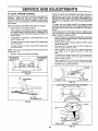
TO LEVEL
,I,II'IlU
I
MOWER
.....
....
ll,Hl",l II n
HOUSING
ADJUSTMENT
TO obtain the best cutting results, the mower housing
should be adjusted so that the front is approximate{y 1/4" to
3/4" lower than the rear when the mower is in its highest
position.
Check adjustment on right side of tractor, Measure distance "D" directly in front and behind the mandrel at bottom
edge of mower housing as shown.
•
Befo re making any necessary adjustments, check that
both front links are equal in length. Both links should be
approximately 10-3/8".
•
If links are not equal in length, adjust one rink to same
length as other link.
•
To Sower front of mower Ioosen nut "E" on both front
links an equal number of turns.
•
When distance "D" is 1/4" to 3/4" lower at front than
rear, tighten nuts "F" against trunnion on both front
Iinks.
•
To raise front of mower, ioosen nut =F' from trunnion on
both front links. Tighten nut "E" on both front links an
equal number of turns.
When distance "D" is 1/4" to 3/4 = lower at front than
rear, tighten nut "F" against trunnion on both front Iinks.
Recheck side4o-side adjustment.
(See Figs. 21 and 22)
-
Raise mower to its highest position.
•
At the midpoint of both sides of mower, measure height
from bottom edge of mower to ground. Distance"A" on
both sides of mawer she uld be the same o r within 1/4"
of each other.
-
If adjustment is necessary, make adjustment on one
side of mower only.
•
To raise one side of mower, tighten Iift tink adjustment
nut on that side.
•
To tower one side of mower, loosen lift link adjustment
nut on that side.
NOTE: Each futl turn of adjustment nut will change mower
height about 1/8".
•
Recheck measurements
after adiusting.
BOTTOM EDGE
QF MOWER TO
GROUND
II,lllUn
FRONT-TO-BACK ADJUSTMENT (See Figs. 23 and 24)
IMPORTANT: DECK MUST BE LEVEL SIDE-TO-SIDE. IF
THE FOLLOWING FRONT-TO-SACK ADJUSTMENT tS
NECESSARY, BE SURE TO ADJUST BOTH FRONT LINKS
EQUALLY SO MOWER WILL STAY LEVEL SIDE-TOSIDE.
Adjust the mower while tractor is parked on level ground or
driveway.
Make sure tires are properly inflated (See
"PRODUCT SPECIFICATIONS" on page 3 of this manual).
If tires are over or undednflated, you will not properly adjust
your mower.
SIDE-TO-SIDE
I
BOTTOM EDGE
OF MOWER TO
GROUND
A
GROUND LINE
FIG. 21
LJFT LINK
ADJUSTMENT
NUT
FIG. 22
FRONT UNKS
21
TRUNNION
FIG. 24
SERVICE AND ADJUSTMENTS
u
i_ ,,,,n
,
i=
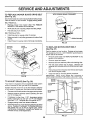
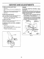
TO REPLACE
(See Fig. 25)
,, ,= H
=
MOWER
BLADE
n,nHi
DRIVE
=
IH= ,,,,,,,m
U
=
,,
I,,,,,,,,,n
IH
,'m
,,
=
=,=
WITH PARKING BRAKE "ENGAGED"
BELT
The mower blade drive belt may be replaced without tools.
Park the tractor on level surface. Engage parking brake,
BELT REMOVAL •
Remove mower from tractor (See =TO REMOVE
MOWER" in this section of this manual).
•
Work belt off both mandrel pulleys and idler pulleys.
•
Pull belt away from mower.
BELT INSTALLATION
-
JAM NUT
•
lnstaIi new belt in reverse order of removal.
•
Make su re belt is in all pulley grooves and inside a!l belt
guides.
°
NUT =A"
_
OPERATING
ARM
Instait mower in reverse order of removal instructions.
FIG. 26
MANDREL
PULLEY
IDLER
PULLEYS
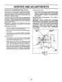
TO REPLACE
MOTION
DRIVE
BELT
(See Fig. 27)
Park the tractor on tevel surface. Engage parr,ring brake.
For assistance, there is a bett instatlation guide decal on
bottom side of Ieft footrest.
MANDREL
PULLEY
BRAKE
Remove mower (See "TO REMOVE MOWER" in this
section of this manual.)
.
Remove upper be{t keeper.
•
*
Remove beft from stationary idler and clutching idler.
Pull beit stack toward rear of tractor.
Remove belt
upwards from transaxte pulley by deflecting belt keepers.
.
Pull belt toward front of tractor and remove downwards
from around engine puIley.
°
Install new belt by reversing above procedure.
IMPORTANT: _,4AKE SURE UPPER BELT KEEPER !6
POStT;ONED PROPERLY BETWEEN LOCATOR TABS,
F_G. 25
TO ADJUST
*
PULLEY
(See Fig. 26)
CLUTCHING
IDLER
Your tractor is equipped with an adjustable brake system
which is mounted on the right side of the transaxte.
if tractor requires more than six (6) feet stopping distance
at high speed in highest gear, then brake must be adjusted.
*
Depress clutch/brake pedal and engage parking brake.
-
Measure distance between brake operating arm and
nut "A" on brake rod.
-
If distance is other than 1-1/2", disengage parking
brake, loosen jam nut and turn r_ut "A" until distance
becomes 1-1/2". Retighten jam nut against nut "A_.
.
Engage parking brake and recheck distance.
•
Road test tractor for proper stopping distance as stated
ai_ove. Readjust if necessary, if stopping distance is
still greater than six (6) feet in highest gear, further
maintenance is necessary, Contact your nearest authorized service center/department.
KEEPER
FIG. 27
22
i i
,
,u,
i
u
lU,ll,
,inn
,ill
i
i,,lll
i
i
ii
i i
i,
i
lu
i
i
ill
i
,,,
SERVICE AND ADJUSTMENTS
ii1,, i
i
TO ADJUST
,111
ipl i
STEERING
,Hi
WHEEL
ii i
ilnnm
ALIGNMENT
•
i
BATTERY
illl ,nnl
ii
n t ,,,11,,
Lead-acid batteriesgener.
and smoking materials away from batate explosivegases. Keep sparks, flame
teries.
Always wear eye protection
when around batteries,
.............................................
_
The front wheel toe-in and camber are not adjustable on
your tractor. If damage has occurred to affect the front
wheel toe-in or camber, contact your nearest authorized
service centeddepartment.
FOR
illlll
ENGINE WITH A WEAK
. ................................
_
CAUTION:
TOE-IN/CAMBER
TO REMOVE WHEEL
(See Fig. 28)
,i
(See Fig. 29)
section of this manual.
WHEEL
i i,m,i
TO START
If steering wheel crossbars are not honzontal (left to nght)
when wheels are positioned straight forward, remove steering wheel and reassemble per instructions in the Assembty
FRONT
i
i
If your battery is too weak to start the engine, it should be
recharged.
If "jumper cables" are used for emergency
starting, follow this procedure:
IMPORTANT:
YOUR UNIT IS EQUfPPED
WITH A 12
VOLT NEGATIVE
GROUNDED
SYSTEM.
THE OTHER
VEHICLE
MUST ALSO
BE A 12 VOLT
NEGATIVE
GROUNDED
SYSTEM.
OO NOT USE YOUR TRACTOR
BATTERY TO START OTHER VEHICLES.
REPAIRS
Block up axle securely.
•
Remove axle cover, retaining ring and washers to allow
wheel removal (rear wheei contains a square key - Do
. not iose).
•
Repair tire and reassemble.
TO ATTACH JUMPER CABLES •
•
On rear wheels only: align grooves in rear wheet hub
and axle. Insert square key.
,
•
Replace washers and snap retait_ing ring securely in
axle groove.
•
•
Replace axle cover.
Cor=_qecteach end of the RED cabie to the POSITIVE
(+) terminal of each battery, taking care not to short
against chassis.
Connect one er_d of the BLACK cable to the NEGATIVE (-) terminal of fully charged battery.
Connect the other end of the BLACK cable to good ,,
CHASSIS GROUND, away from fuel tank and battery.
TO REMOVE CABLES, REVERSE ORDER ,
BLACK cable first from chassis and then from the fully
charged battery.
°
RED cable last from both batteries.
WASHERS
NEGATIVE
POSITIVE TERMINAL
RETAINING
RING
TERMINAL
Q
AXLE COVER
I
_SQUARE
KEY
(NEAR WHEEL ONLY)
FIG. 28
CHARGED
BATTERY
POSITIVE
NEGATIVE
TERMINAL
FIG. 29
23
TERMINAL
Ill
I
.............................................
SERVICE
ill i
TO REPLACE
•
•
i rl ,ul
ii
HEADLIGHT
AND ADJUSTMENTS
i
,lllllU
i'11111iil!l
•
AND RELAYS
Check wiring. See electrical wiring diagram in the
Repair Parts section of this manual.
TO REPLACE
FUSE
J,l,,llll
I
I
HI
CONTROL
CABLE
•
With engine not running, move throttle control lever
from slow (,=b) to choke (N) position. Slowly move
lever from choke (["4) to fast (,t_) position.
o
Check that holes =A" in governor control lever and hole
in governor plate line-up. If holes "A" are not aligned,
loosen clamp screw and move throttle cable until holes
are aligned. Tighten clamp screw securely.
GOVERNOR
CONTROLLEVER
Replace with 30 amp automotive-type plug-in fuse. The
fuse holder is located behind the dash.
TO REMOVE HOOD AND GRILL
(See Fig, 30)
...............
The throttle control has been preset at the factory and
adjustment should not be necessary. Check adjustmentas
described below before loosening cable. If adjustment is
necessary, proceed as follows:
Loose or damaged wiring may cause your tractor to run
poorly, stop running, or prevent it from starting.
•
iii1,,,,11[111111
TO ADJUST THROTTLE
(See Fig. 31)
Rep{ace bulb in holder and push bulb holder securely
back into the hole in the backside of the grill,
Close hood.
INTERLOCKS
,11,
ENGINE
BULB
Raise hood.
Pull bulb holder out of the hole in the backside of the
grill.
•
i
GOVERNOR
CONTROL PLATE
ASSEMBLY
,
Raise hood.
•
Unsnap headlight wire connector.
•
Stand in front of trector. Grasp hood at sides, titt toward
engine and lift off of tractor.
•
To replace, reverse above procedures.
HOLES"A"
CLAMP
SCREW'
HOOD
FIG. 31
HEADUGHT
WIRE
CONNECTOR
FIG. 30
24
THRO'I-TL_
CABLE
TO ADJUST CARBURETOR
(See Fig. 32)
ACCELERATION
TEST
-
The carburetor has been preset at the factory and adjustment should not be necessary. However, minor adjustment may be required tocompensate for differences in fuet,
temperature, altitude or load. If the carburetor does need
adjustment, proceed as follows:
•
In general, turning idle mixture valve in (clockwise) decreases the supply of fuel to the engine giving a leaner fuetJ
air mixture. Turning the idle mixture valve out (counterclockwise) increases the supply of fuel to the engine giving
a richer fuel/air mixture.
High speed stop is factory adjusted.
Do not adjust damage may result.
IMPORTANT:
NEVER TAMPER
WiTH THE ENGINE
GOVERNOR,
WHICH IS FACTORY
SET FOR PROPER
ENGINE SPEED. OVERSPEEDtNG
THE ENGINEABOVE
THE
FACTORY
HIGH
SPEED
SETTtNG
CAN BE
DANGEROUS,
IF YOU THINKTHE
ENGINE-GOVERNED
HIGH SPEED NEEDS ADJUSTING,
CONTACT
YOUR
NEAREST
AUTHORIZED
SERVICE
CENTER/
DEPARTMENT,
WHICH HAS PROPER EQUIPMENT
AND
EXPERIENCE
TO
MAKE
ANY
NECESSARY
ADJUSTMENTS.
IMPORTANT: DAMAGE TO THE NEEDLE VALVE AND
THE SEAT IN CARBURETOR MAY RESULT _FSCREW IS
TURNED iN TOO TIGHT.
PRELIMINARY
SETTING -
•
Air cleaner assembly must be assembled to the carburetor when making carburetor adjustments.
-
Be sure the throttle control cable [s adjusted propedy
(see above).
Move throttle control lever from slow
position.
If engine hesitates or dies,
valve out (counterclockwise)
1/8 turn.
continue to adjust, if necessary,
until
ates smoothly.
THROTTLE
LEVER
IDLE SPEED
SCRE"N
°
With engine off turn idle mixture valve in (clockwise)
closing it finger tight and then turn out (counterclockwise) 1 full turn.
F_NAL SETTING •
Start engine and allow to warm for five minutes. Make
final adjustments with engine running and shift/motion
control lever in neutral (N) position.
•
Move throttle control lever to stow (._) position. With
finger, rotate and hold throttle lever against idle speed
screw. Turn idle speed screw to attain 1750 RPM.
•
While still holding throttle Iever against idle speed
screw, turn idle mixture valve in (clockwise) until engine begins to die and then turn out (counterclockwise)
until engine runs rough, Turn valve to a point midway
between those two positions. Release throttle lever.
RG. 32
25
(,a_) to fast (_,)
turn idle mixture
Repeat test and
engine acceler-
ENGINE
Immediately prepare your tractor for storage at the end of
the season or if the tractor wilt not be used for 30 days or
more.
.
. ................
i
[[
[[
[i
[[[[[
[[[[[
[
[
i
[il[j
gasoline in the tank inside a building
where fumes may reach an open flame
or spark.
Allow the engine to cool
before storing in any enclosure.
n,,n
,11 r
FUEL SYSTEM
_
i
IMPORTANT:
iT IS IMPORTANT TO PREVENT GUM
DEPOSITS FROM FORMING IN ESSENTIAL FUEL
SYSTEM PARTS SUCH AS CARBURETOR, FUEL FILTER,
FUEL HOSE, OR TANK DURING STORAGE.
ALSO,
EXPERIENCE INDICATES THAT ALCOHOL BLENDED
FUELS (CALLED GASOHOL OR USING ETHANOL OR
METHANOL) CAN ATTRACT MOISTURE WHICH LEADS
TO SEPARATION AND FORMATION OF ACIDS DURING
STORAGE.
ACIDIC GAS CAN DAMAGE THE FUEL
SYSTEM OF AN ENGINE WHILE IN STORAGE.
J
I
!
,,,,u,,
TRACTOR
Remove mower from tractor for winter storage. When
mower is to be stored for a pedod of time, clean it thoroughty, remove all dirt, grease, leaves, etc, Store in a
clean, dry area.
•
Clean entire tractor (See"CLEANING" in the Customer
Responsibilities section of this manual).
•
Inspect and replace belts, if necessary (See belt replacement instructions in the Service and Adiustments
section of this manuat).
•
Lubricate as shown in the Customer Responsibilities
section of this manual.
•
Be sure that all nuts, bolts and screws are secureiy
fastened. Inspect moving parts for damage, breakage
and wear. Replace if necessary.
,
Touch up all rusted or chipped paint surfaces; sand
lightly before painting,
Fully charge the battery for storage.
*
After a pedod of time in storage, battery may require
recharging.
,
,,
Drain the fuel tank.
•
Start the engine and Iet it run until the fuel Iines and
carburetor are empty.
•
Never use engine or carburetor cleaner productsin the
fuel tank or permanent damage may occur,
Use fresh fuel next season.
•
NOTE:
Fuel stabilizer is an acceptable aftemative in
minimizing the formation of fuel gum deposits during storage. Add stabilizer to gasotine in fuel tank or storage
container. Atways foitow the mix ratio found on stabilizer
container. Run engine at Ieast 10 minutes after adding
stabilizer to attow the stabilizer to reach the carburetor, Do
not drain the gas tank and carburetor if using fuel stabilizer.
ENGINE
OIL
Drain oil (with engine warm) and replace with clean engine
oil. (See "ENGINE" in the Customer Responsibilities
section of this manual).
BATTERY
.
•
CYLINDERS
To hetp prevent corrosion and power leakage during
iong periods of storage, battery cables should be
disconnected and battery cteaned thoroughly (see "TO
CLEAN BATTERY AND TERMINALS" in the Customer Responsibifities section of this manuat).
After cleaning, leave cables disconnected and place
cables where they cannot come in contact with battery
terminals.
-
Remove spark ptug(s).
-
Pour one ounce of oil through spark plug hole(s) into
cylinder(s).
•
Turn ignition key to "START" position for a few seconds
to distribute oil.
o
Replace with new spark plug(s).
OTHER
•
Be sure battery drain tube is securely attached.
•
Do not store gasoline from one season to another.
•
If battery is removed from tractor for storage, do not
store battery directly on concrete or damp surfaces.
=
Replace your gasoline can if your can starts to rust,
Rust and/or dirt in your gasoline will cause problems.
•
if possible, store your tractor indoors and cover it to
give protection from dust and dirt.
o
Cover your tractor with a suitable protective cover that
does not retain moisture. Do not use plastic. Plastic
cannot breathe which allows condensation to form and
will cause your tractor to rust.
IMPORTANT: NEVER COVER TRACTOR WHILE ENGINE
AND EXHAUST AREAS ARE STILL WARM.
26
i ii
i,irl,l_,H,
i I
.....................................
_
TROUBLESHOOTING
.
inl
CAUSE
Will not start
i
iiii
iii
t.
Out of fue!.
1.
Fitl fuel tank.
Engine not "CHOKED" properly.
Engine flooded.
Bad spark ptug.
Dirty air filter.
Dirty fuel filter.
Water in fuel.
2.
3.
4.
5.
6.
7.
See "TO START ENGINE7 in Operation section.
Wait several minutes before attempting to starL
Replace spark ptug.
Clean#apiece air filter.
Replace fuel filter.
Drain fuel tank and carburetor, refill tank with fresh
gasolineand replace fuel filter.
Check all wiring,
Contact an authorized service facility.
Contact an authorized service facility.
iii
jl
Engine clicks but will not
start
,i
i,u, i
1.
2.
3.
4.
Cluto}'vbrake pedat not depressed.
Attachment clutch iS engaged.
Weak or dead battery.
Blown fuse.
5.
6.
7.
8.
9.
t.
2.
3.
4.
1.
2.
3.
4.
5.
&
7.
8.
9.
10.
11.
12.
I3.
14.
I5.
Excessive
i
,,,,
vibration
Clean/replace air filter.
Replace spark plug.
Recharge or replace battery.
Replace fuel filter.
Drain fuel _n_[ and refi_fwith fresh gasoline.
Check all widng.
Contact an autho#zed service facility.
Contact an authenzed service facility.
....
i
i
Corroded battery terminals.
Loose or damaged widng.
Faulty ignition switch.
Fautty sotenoid or starter.
FauRy operator presence switch(as),
1.
2.
3.
4.
5.
&
7.
8.
9.
Depress cfutctvbreke pedal
Disengage attachment clutch.
Recharge or replace battery.
Replace fuse.
Clean t3attery terminals.
Check a_lwiring.
Check/replace _gnitIon switch.
Check/replace solenoid or starter.
Contact an authorized service facJlity.
Weak or dead battery.
Corroded battery terminals.
Loose or damaged widng.
Faulty Solenoid or starter.
I.
2.
3.
4.
Recharge or replace battery.
Clean battery terminals.
Check all wi#ng.
Check/replace sotenoid or starter.
1.
2.
3.
4.
5.
6.
7.
8.
g.
Set in "Higi']er Cut" posi#onireduoa speed.
Adjust Enrottle control
Clean underside of mower housing.
Clean!replace air filter.
Check nil leveVchange oil.
Clean and regap or change spark plug.
Replace fuel filter.
Drain fuel tank and refill with fresh gasoline.
Drain _el tank and carburetor, refill tank withfresh
,IHI
,,,Jl
Loss of power
iiii
1.
2.
3.
4.
5.
6o
7.
8.
Dim/air filter.
Bad spark piug.
Weak or dead battery.
Dirty fuel filter.
Stale or dirty fuel.
Loose or damaged winng.
Carburetor out of adiustment`
Engine valves out of adjustment.
ii,l,lUUll
imll
i
8.
9.
t0.
i
Engine will not turn over
,u
Loose or damaged wiring,
Carburetor out of edtustmant
Engine valves out of adjuemnent`
1.
2.
3.
4.
5.
6.
7.
8.
iiii
CORRECTION
iii
Hard to start
,,i
POINTS
2.
3.
4.
5.
6.
7.
8.
9,
10.
i
II I'1
iiiii
PROBLEM
rill, i
. ........
ii,nl
i
Cutting too much grm_,Wtoo fast.
Thro_e in "CHOKE" pealtJen.
Build-up of grass, leaves and trash under mower.
Dirty air filter.
Low aif tevet/d|mi oil.
Fautty spark plug.
0itly fuet Alter.
Stale or dirty fuel.
Water in fuel
10.
11.
12.
13.
14.
I5.
Spark plug wire Jcese.
Dirty engine air screerVfins.
Oittytc_ogged muffler.
Lc'_se or damaged widng.
Carburetor out of adjustment`
Engine valves out of adjusm_nt.
gasoline and re#lace fuet filter.
Connect and i_ghtan spark plug wire.
Clean engine air screen/fins.
Clean/replace muffler.
Check all wiring.
Contact an authorized service fas_ltty.
Contact an authorized service facility.
,,...........
t.
2.
Wen, bent or loose blade.
Bent blade mandrel.
3.
Loose/damaged
1.
2.
3.
part(s).
27
Replace blade. T_ghten blade bolt.
Replace blade mandrel.
T;ghten Ioose part(s). Replace damaged
parts.
u
,111
iii
nlrlrl
unl
i
i/
nn
nlu
i
t
, iiiiiiiiii
TROUBLESHOOTING
iii
i
iii
i
i i
i
ii,n
n
iii
,i,ii
i
i i
,llUUll
i
iii
CAUSE
Engine contfnuee to run
when operator _eaves seat
with attachment ctutch
engaged
!.
Fau{_ _emto_safe_
Poorcut-uneven
1.
2.
3.
4.
Worn, bent or loose blade.
Mower deck net level
Buildup of gm_, leaves, and trash under mower.
Bent biade mandrel
5.
Clogged mower deck vent holes from buildup of
grass, leaves, and trash around mandrels.
iiii HIll
I
jlnl
r,nl
iii
,in
POINTS
i
in
iiiii
nnlnllllUl
n
i
iiii
n
ml
presence_ntmt s_em.
1.
Check w#ing, switches and connections.
|f not
corrected, contact an authorized so.ice facility.
1.
2.
Replace blade. Tighten blade bolt.
Levelrm_wer deck.
3.
4.
5.
Clean undersideofmower housing.
Reptace blade mandrel.
Clean around mandrels to open vent ho_s.
1.
Obstruction
incfutch mechanism,
1,
Remove 0bstructJon.
2.
3.
4.
Worn/damaged mower dnve beit.
Frozen idler puttey.
Frozen btade mandrel
2.
3.
4,
Repiece mower dr_ve belt.
Replace idler pulley.
Replace btade mandrel.
1.
2.
3.
4.
Engine speed too slow.
Travel speed too fast.
Wet grass.
Mower deck not level
1.
2.
Place thro_e comrol in "FAS'P position.
Shift to slower speed.
3.
4.
Atlow gra_ to dry before mowing.
Level mower deck.
5.
6.
7.
8.
Low/uneven tire air pressure.
Worn, bent or loose blade.
Buildup of grass, leaves and trash under mower.
Mower drive belt worn.
9.
10,
t 1.
Btades improperly installed.
Improper biades used.
CIogged mower deck vent holes from buildup of
gross, leaves, _d tm_sh around mandrels.
,,,,, ......
Poor grass discharge
ii
iiu
CORRECTION
PROBLEM
Mower b;adee wiJl not
fof_te
,,i,n
ii
,In
,Ill
i
i i
JI
Headlight(s) not working
(if so equipped)
ii,
Battery witl not charge
5.
6.
7.
&
9.
10.
1 t,
Check tires for proper sir pressure.
Replace/sharpen blade. T'iginten blade bolt.
Clean underside of mower housing.
Replace mower drive belt.
Rsinstai_ blades sharp edge down.
Replace with blades J{sted in _is manual.
Clean around m&ndrais to open vent hotes.
I
1.
Switch is "OFF*'.
I.
rum switch "ON'.
2.
3.
4-,
5.
Butb(s) burned out.
Faulty light switch.
Loose or damaged widng.
Blown fuse.
2.
3.
4.
5.
Repiace bulb(s).
ChecK/replace light switCh.
Chec_ wiring and connec_ons.
F_e_tace fuse.
iiiiiiiiiii
,,,,,,,,,,.,,,,,,, i
1.
2.
_ad battery ca#(S).
Po{3r cable connections,
3,
4.
Faulty regulator [if so equipped).
Faulty sitemator.
_.
2,
3,
4.
i
1.
Engine throttle control not set at 'BLOW*
position for 30 seconds before stepping engine.
28
t.
,
I,HI rll I
Reptace battery.
ChecK/clean aJl connections.
Replace regulator.
Replace attemator.
Jl iii
Engine "backfires"
when turning engine
,,OFF =
_ .....
iii
i1,11
iiii
i
i
Move thro_e control tO "SLOW" position and aJlow
to idle for30 seconds before stopping engine,
i
15 HP 42" TRACTOR
- - MODEL NUMBER
917.257644
SCHEMATIC
RED
o111o
"( I"
BUICK
BATTERY
RED
RED
w_rrE
,
REED
_
FUSE 30 AMP.
STARTER
CLUTCH
/BRAKE
_;L_O;
(PEDAL UP)
IGNITION
SWITCH
,,........
,
I
(
-----]
I
---
°_°_
t ____._
:o
81.ACK
sEAT
SW,TCH
1 ........
(NOT OCCUPIED)
(>}........
ATT'MENT CLUTCH
(CLUTCH OFF)
GROUNDING
CONNECTOR
e
IGNITION
UNIT
BLACK
©
SPARK
PLUG
tt
•
/'3
I
8LUH
1
Q-L_LL_AJ €,
r ......
=1Iii,
III
1
AFTER FIRE SOLENOID
meg
'......'
ORANG_
_(_
BmOWN
c
BLAC_
R
_EAOUGHT I_t
SW_TCH (OFF)
IGNr[1ON SWITCH
POSmON
j
oN
CIRCUIT
B.L ...........
NON-REMOVABLE
CONNECTIONS
WIRING INSULATED
CLIPS
NOTE: IF WIRING INSULATED
CUPS WERE REMOVED FOR
SERVICING OF UNIT, THEY
SHOULD BE REPLACED TO
PROPERLY SECURE YOUR
WIRING
_
REMOVABLE
CONNECTIONS
29
___2->_EADLIGHTS
NOTE
YOUR TRACTOR IS EQUIPPED WITH
A SPECIAL ALTERNATOR SYSTEM.
THE LIGHTS ARE NOT CONNECTED
TO THE BATTERY, BUT HAVE THEIR
OWN ELECTRICAL SOURCE.
BECAUSE OF THIS, THE BRIGHTNESS
OF THE LIGHTS WILL CHANGE WITH
ENGINE SPEED. AT iDLE THE LIGHTS
WILL DIM. AS THE ENGINE IS
SPEEDED UP, THE LIGHTS WILL
BECOME THEIR BRIGHTEST.
•
REPAIR PARTS
15 HP 42" TRACTOR
- - MODEL
NUMBER
917.257644
ELECTRICAL
22
21
41
36 38
35
39
\
2
1
f
I
i
]
30
REPAIR
PARTS
15 HP 42" TRACTOR
-- MODEL
NUMBER
917.257644
ELECTRICAL
KEY
NO.
PART
NO.
1
2
3
4
6
7
8
9
15
t6
t9
20
21
123899X
747604!2
STD551025
STD551125
STD541025
109238X
144940
109596X
144935
144939
STD551125
73350400
136850
22
23
24
25
26
28
29
30
31
32
33
34
35
36
37
38
39
40
41
42
43
44
70
4152J
STD551225
4799J
124503X
108824X
4207J
!21305X
144921
140400
141226
140403
110712X
I08236X
STD601005
104445X
140336
109553X
140414
71110408
131563
138406
73640400
140422
NOTE:
DESCRIP_ON
Battery Service W/Caps
Bolt, Hex Head 1/4-20 unc x 3/4
Washer
Washer
Nut
Tube, Plastic, 12"
Case, Battery W/2 Holes WiBrty
Cramp, Hose
Screw Cap Hex Nylon 3/8-16 x 1
Nut Clip Fast 3/8
Washer, Lock
Nut, Hex, Jam I/4-20 UNC
Harness, Light Socket
(Includes Key # 33)
Bulb, Light
Washer
Cabte, Battery, 6 Gauge, Red, t 1"
Cable, Battery, 6 Gauge, Red, 45"
Fuse, 30 Amp
Cable, Ground, 6 Gauge, Black, 12"
Switch, Plunger
Switch, Ignition
Nut, ignition
Cover, Key Switch
Key, Ignition
Switch, Light
Bracket, CIutch Switch
Screw
Switch, Interlock, Clutch, 2 Terminal
Bracket, Interlock Switch
Switch, Interlock, Clutch, 4 Terminal
Harness, Ignition
Bott, Hex Head, Fin.
Cover, Terminal, Red
Sofenoid
Nut Keps Hex 1/4-20 UNC
Harness Engine B&S
All component dimensions given in U.S. inches
1 inch = 25.4 mm
31
REPAIR PARTS
15 HP 42" TRACTOR
CHASSIS
- - MODEL
NUMBER
917.257644
AND ENCLOSURES
17
21
_4
21
26
18
25
29
16
1
28
26
33
10
3
39
32
26
t4
REPAIR PARTS
15 HP 42" TRACTOR
CHASSIS
- .. MODEL NUMBER
917.257644
AND ENCLOSURES
KEY
NO.
PART
NO.
1
2
3
4
5
6
7
8
9
10
11
t2
13
14
15
140341
140356
17490612
19131216
11050600
140169
126842X
126471X
140637X013
72140608
135464
11030400
126276X
17490608
74180512
16
17
18
19
21
22
24
25
26
27
28
29
30
31
33
34
35
38
39
t00
--
STD541431
131445X459
126938X
17521312
!22933X
124479X
STD523710
19131312
STD541437
17030808
140137
124029X
140001X459
136619
!05465X459
105484X_59
STD533707
139886
139887
105037X
5479J
NOTE:
DESCRIPTION
Chassis Assembly
Drawbar
Screw, Thd. Roll. 3/8-16 x 3/4
Washer 13/32 x 3/4 x 16 Gauge
Washer, Lock, Extemat Tooth
Saddle
Shield Ht Hood Kohi/Dia Engine
Clip Insulator .406 Mtg Hole
Dash
Bott, Cam'age 3/8-16 x 3/4
Panel, Dab,h, L.H.
Washer Lock I/4 lnt/Ext Tooth
Panel, Dash, R.H.
Screw Thdrol 3/8-16 x 1/2
Screw, Machine, Truss Head
5/16-18 UNC x 3/4
Nut
Hood Assembly
Bumper, Hood
Screw, Sftd. Hex Hd. w/Pl Washer
Rivet, Ratchet, Ny!on
Washer, Nylon .28 x .75 x .t9
Bolt
Washer 13/32 x 13/18 x 12 Gauge
Nut
Screw Spidedock Hex Hd #8-1/2
Gdll
Lens, Headlight Bar, Clear
Fender
Bracket, Fender
Footrest, L.H,
Footrest, R.H.
Bolt
Pivot Bracket Assembly, LH.
Pivot Bracket Assembly, R.H.
Strip Foam 18"
Plug, Button
All component dimensions given in U.S. inches
1 inch = 25.4 mm
33
REPAIR PARTS
15 HP 42" TRACTOR
" " MODEL NUMBER 917.257644
DRIVE
1
72
56
84
65
56 j
21
87
18
5
34
61
26
75
34
REPAIR PARTS
15 HP 42"
TRACTOR
- - MODEL
NUMBER
917.257644
DRIVE
KEY
NO.
1
PART
NO.
142603
2
3
4
5
6
6
10
11
12
13
110422X
123666X
12000028
121520X
17490512
141003
76020416
105701X
19151216
71040412
14
15
16
18
19
21
22
24
25
26
27
28
29
30
31
32
34
35
36
37
38
39
40
41
42
44
45
STD551125
74780544
STD541431
STD523710
STD541437
106933X
130804
STD541237
106888X
STD551037
STD56121Q
140448
124236X
130807
127275X
STD523107
122424X
120183X
STD551062
STD571810
123674X
STD523727
4470J
109070X
19131312
105706X
II0812X
DESCRIPTION
Transaxle, Dana, 6 Speed,
Mode! Number 4360-79
Spring, Extension, Brake
Pulley, Transaxle
Ring, Retainer
Strap, Torque
Screw, Thd., Roll 5/16-18 x 3/4
Lever, Shift
Pin, Cotter
Washer, Shift Plate
Washer 15/32 x 3/4 x 16 Gauge
Bolt, Hex Head, Fin.
1/4-28 UNF x 3/4 Grade 8
Washer
Bolt, Hex Head 5/16-18 x 2-3/4
Nut, Crownicck 5/16-t8 UNC
Boft
Nut
Knob
Rod, Brake
Nut
Spring, Brake Rod
Washer
Pin
Rod, Parking Brake
Cap, Parking Brake, Red
Bracket, Transax{e
Keeper, Bett, L.H.
Bolt
Shaft Assembly, Foot Pedal
Bearing, Nylon
Washer
Rotl Pin
Putley, idler, Flat
Bott
Spacer, Split .395 x .59
Keeper, Belt, Retainer
Washer 13/32 × 13/I6 × 12 Gauge
Bearing, Nylon
Washer, Hardened
KEY
NO.
PART
NO.
46
47
48
49
50
51
52
53
55
56
57
58
59
61
62
63
64
12000039
127783
123789X
123205X
STD523715
STD541437
STD541431
105710X
105709X
STD523712
130801
127274X
140312
17490612
8883R
140186
71170764
65 ST0551143
66
129921
70
134683
72
19132012
74
109502X
75
121749X
76 STD581075
77
123583X
78 121748X
80 131488
81 136932
82 123782X
83 19171218
84
132182
85 73530400
86 71208
87 19212016
88 12000008
89 139964
90
124346X
100 19111216
DESCRIPTION
Ring, Klip
Pulley, Idler, V-Groove, Plastic
8ellcrank Assembly
Retainer, Belt
Bolt
Nut Crown Lock 3/8-16 UNC
Nut Crown Lock 5/16-18 UNC
Link, Ctutch
Spring, Clutch Return
Bolt Fin He× 3/8-16 x 1-t/4
V-Belt, Ground Drive
Keeper, Belt, R.H.
Keeper, Belt, Center Span
Screw, Thd., Roll 3/8-16 x 3/4
Cover, Pedal
Pulley, Engine
Bolt, Hex Head, Fin.
7/16-20 x 4 Grade 5
Washer
Keeper, Belt, Engine, LH.
Guide, Mower Ddve Belt, R.H.
Washer 13/32 x 1-1/4x !2 Gauge
Spacer, Split .80 × .94
Washer 25/32 x 1-l/4 x 16 Gauge
E-Ring
Key, Square 2.0 × .1845/.1865
Washer 25/32 x 1-5/8 x I6 Gauge
Arm, Shift
Shaft Assembty
Spdng, Torsion
Washer 17/32 x 3/4 x 16 Gauge
Tie Rod
Nut, Ny_ock
Bushing, Pivot
Washer
E-Ring
Console, Shift, 6 Speed, N/Ignition
Nut, Self-Threading, Washer Hd 1/4
Washer tl/32 x 3/4 x 16 Go.
NOTE: All component dimensions given in U.S. inches
! inch = 25.4 mm
35
REPAIR PARTS
15 HP 42" TRACTOR
STEERING
- - MODEL NUMBER
917.257644
ASSEMBLY
47
36
14
REPAIR PARTS
15 HP 42" TRACTOR
STEERING
- - MODEL NUMBER
917.257644
ASSEMBLY
KEY
NO.
PART
NO.
1
2
3
4
5
6
7
8
9
10
11
12
13
14
15
16
17
18
19
20
21
22
139768
142033
135227
135228
6266H
121748X
19272016
12000029
3366R
130468
STD551137
73610600
110438X
74011056
73901000
132624
132614
57079
I24035X
126684X
STD551125
71070410
23
24
25
26
27
28
29
30
32
36
37
38
39
40
41
42
43
46
47
127501
109816X
124036X
126847X
136874
19131416
1749O612
STD561210
130465
132196
STD611005
139769
19133808
STD541537
104820X
124-417X
121749X
t21232X
8855M
NOTE:
DESCRIPTION
Steedng Wheel
Front Axle Assembly
Spindle Assembly, L.H.
Spindle Assembly, R.H.
Beadng, Race, Thrust, Hardened
Washer 25t32 x 1-5/8 x 16 Gauge
Washer 27/32 x 1-1/4 x 16 Gauge
Ring, Klip
Bearing, Steering Column
Link, Drag
Washer, Lock
Nut, Hex, Fin. 3/8-24 UNF
Spacer, 8earing, Front Axle
Bolt, Hex Head 5/8-11 UNC x 3-1/2
Nut, Lock, Flange 5/8-11 UNC
Pfn, Axle 5/8 x t.56/1.54
Shaft Assembly, Steedng
Washer, Thrust .515 × .750 x .033
Support, Shaft
Washer, Shim t/4 x 5/8 x .062
Washer
Screw, Hex Socket Head
1/4-20 x 5/8
Pittman Shaft Assembly
Nytiner, Snap-In
Bracket, Steering
Bushing, Link, Drag
Gear, Sector
Washer 13/32 x 7/8 x t6 Gauge
Screw, Thd., Roll. 3/8-16 x 3/4
Fin
Rod, Tie
Bushing, Steedng
Screw
Insert, Steerfng Wheel
Washer 13/32 x 2-3/8 x 8 Gauge
Gripco Nut
Adaptor, Steedng Wheel
Boot, Steering Shaft
Washer 25/32 × lq/4× 16 Gauge
Cap, Spindle
Fitting, Grease
Allcomponent dimensions given inU.S. inches
1 inch = 25.4 mm
37
REPAIR PARTS
15 HP 42" TRACTOR
- - MODEL NUMBER
917.257644
SEAT ASSEMBLY
j8
10
KEY
NO,
PART
NO.
1
2
3
4
5
6
7
8
9
I0
t2
13
14
127438X
140551
STD523710
19131610
145006
STD541437
124181X
17490616
19131614
140552
12!246X
121248X
72050411
71
DESCRIPTION
Seat
Bracket, Pivot, Seat
Bolt
Washer 13/32 x 1 x 10 Gauge
Clip, Push-{n Hinged
Nut
Spring, Seat
Screw, Thd., Roll 3/8-16 x 1
Washer 13/32 x 1 x 14 Gauge
Pan, Seat
Bracl(et, Switch Mounting
Bushing, Snap
B(31t,Carriage 1/4-20 x 1-3/8
KEY
NO.
PART
NO.
15
16
17
21
22
23
134300
12!250X
t23976X
139888
ST0541431
74780814
24
25
26
19171912
1270t8X
STD551t50
DESCRIPTION
Spacer, Sptit .28 x .88
Spring
Locknut, Flange 1/4 Grade 5
Bolt, Shoulder 5t16-18 UNC
Nut
Bolt, Hex Head, Fin.
1/2-13 x 7/8 Grade 5
Washer 17/32 x 1-3/16 x 12 Gauge
Bolt, Shoulder 5/16-18 x .62
Washer, Lock
NOTE: All component dimensions
1 inch =25.4 mm
38
given in U.S, inches
REPAIR PARTS
15 HP 42" TRACTOR
-- MODEL
NUMBER
917.257644
DECALS
13
6
3
18
7
7
1
18
4
16
10
19
5
\
11
8
12
t3
14
KEY
NO.
1
2
3
4
5
6
7
8
9
!0
11
12
PART
NO.
138955
142239
143735
143736
132674
!33644
142235
133178
128314
137537
4900J
109!99X
WHEELS
15
KEY
NO.
DESCRIPTION
Decal,
Decat,
Decal,
Decal,
Decal,
Decal,
Decal,
Decal,
Decal,
Decal,
Decal,
Decat,
Operating _nstruction
B&S Diamond rCiGold OHV
Hood, R.H.
Hood, L.H.
Grill, LT4000
Customer Maintenance
Side Panel, IC Gctd
Mower, 3 fn One
Fender, Craftsman
Caution, English
Clutch/Brake, English
V-Belt Drive Schematic
PART
NO.
I3
t4
15
131473
136832
!05466X
16
t7
18
19
21
----
140837
133179
142234
131265
138836
138311
145418
145419
DESCRIPTION
Decal, Chassis, 5 Speed/42"
Decal, V-Belt Schematic
Decal, Pad Footrest Rbr Sq
Craftsman
Decal, Parking Brake Saddle
Decal, Mower QC System
Decal, Ins. Hood 15HP OHV White
Decal, Lightbo×, Grill
Decal, Dash Lawn Tractor St[
Decal, Lift Handle
Owner's Manual, English
Owner's Manual, Spanish
& TIRES
KEY
NO.
1
2
3
4
11
39
PART
NO.
59192
65139
!06222X
59904
5
6
7
8
9
10
106732X427
278H
9040H
106t08X427
106266X
7152J
11
104757X
DESCRIPTION
Valve Cap, Tire
Stem, Valve
Tire, Front
Tube, Front Tire
(Not Provided, Service Item Only)
Rim, Front
Fitting, Grease (Front Wheel Only)
Bearing, Ftange (Front Wheel Only)
Rim, Rear
Tire, Rear
Tube, Rear "Rre
{Not Provided, Service Item Only)
Cap, Axle
_EPAI_ PART8
ENGINE
15 HP 42', TRACTOR.
" MODEl.
NUMBER
917.257644
2
13
4
8
31
40
3O
29
2O
REPAIR PARTS
15 HP 42" TRACTOR--
MODEL NUMBER
917.257644
ENGINE
KEY
NO.
PART
NO.
1
2
132759
17720410
3
140590
4
13
14
15
16
18
19
20
21
22
23
24
29
30
31
32
33
37
38
137352
125593X
13280324
13200300
STD551237
136718
105839X
105838X
STD551025
123650X
128953X
STD601005
137180
127057X
109202X
123549X
t23487X
137O40
---
40
44
124028X
17490412
46
62
72
78
19091416
STD55!131
71070512
17490620
NOTE:
DESCRIPTION
Control, Throttle
Screw, Hex Head, Thread Cutting
!/4-20 x 5/8
Engine, B&S, 15Hp Diamond Turbo
Screen Model No. 28N707,
Type NO. 0160-01
Muffler
Gasket, Exhaust
Nipple, Pipe 3/8 NPT x 3
Elbow, Standard 90 °, 3/8-18 NPT
Washer
Shietd, Heat
Receptacle, 1/4 Turn
Retainer, 1/4 Turn
Washer
Stud, 1/4 Turn
Shieid, Heat
Screw
Arrestor, Spark
Pinch Weld, Hood
Tank, Fuel
Cap Assembly, Fuel Tank, vented
Cramp, Hose
Line, Fuel
Plug, Oil Drain
(Order From Engine Manufacturer)
Bushing, Snap, Fuet Line
Screw, Hex Washer Head, Thd., Roll.
1/4-20 x 3/4
Washer 9/32 x 7/8 x 16 Gauge
Washer, Lock
Screw, Hex Cap Head 5/16-18 x 3/4
Screw, Thd., RoIL &J8-!8 x 1-1/4
All component dimensions given in U.S. inches
1 inch = 25.4 mm
41
REPAIR PARTS
15 HP 42" TRACTOR
MOWER
- - MODEL NUMBER
917.257644
LIFT
7
22
21
_2
•
3
3°
\
11
13
19
13
2O
15
32
161718
2O
19
13---_
15
32
42
20
REPAIR PARTS
15 HP 42" TRACTOR
MOWER
- - MODEL NUMBER
917.257644
LIFT
KEY
NO.
PART
NO.
1
2
3
4
5
6
7
8
t0
11
12
13
15
16
17
18
136973
122507X
105787X
12000002
19211621
120183X
125631X
122365X
122512X
139865
139866
4939M
127218
73350800
130171
73800800
19
20
21
22
23
24
25
26
27
28
29
30
31
32
139868
3!46R
19151216
12000037
110807X
19131016
2876H
76020308
126971X
73350600
138057
110810X
140302
73810600
DESCRIPTION
Lift Lever Inner Wire Assembly
Shaft Assembly, Lift
Pin, Groove
E-Ring
Washer 21/32 x 1 x 21 Gauge
Bearing, Nylon
Gdp, Handte, Fluted
Button, Plunger, Red
Spdng
Link, Lift, LH.
Link, Lift, R.H.
Retainer Spnng
Link, Front
Nut, Hex, Jam 1/2-t3 UNC
Trunnion
Locknut, Hex, with Washer Insert
1/2-13 UNC
Arm, Suspension, Rear
Retainer Sp#ng
Washer 15/32 x 3/4 x 16 Gauge
Ring, Klip
Nut, Special
Washer 13/32 x 5/8 x 16 Gauge
Spnng
Pin, Cotter 3/32 × I/2
Rod, Adjust, Lift
Nut, Hex. Jam 3/8-16 UNC
Knob, Infinite Height Adjustment
Trunnion, Depth Stop
Bearing, Pvt_ Lift Spherical
Nut, Hex 3/8-24 w/Nylon Insert
NOTE: All component dimensions given in U.S. inches
1 inch = 25.4 mm
43
REPAIR PARTS
15 HP 42" TRACTOR
MOWER
- - MODEL NUMBER
917.257644
DECK
76
68
77
37
74'
73
46
71
t
105
s6_
52
34
.33
32
31
45
105
106
21
113 111
114
2">
24
25
\
26
2
16
28
_"
29
,18
18
J
J
17
1
113
44
27
REPAIR PARTS
15 HP 42" TRACTOR
MOWER
- - MODEL
NUMBER
917.257644
DECK
KEY
NO.
PART
NO.
1
2
3
4
5
6
8
9
10
11
12
13
144393
STD533107
138017
138440
STD624008
130832
850857
STD551137
140296
134149
129895
!37645
I4
15
16
17
18
19
20
21
22
23
24
25
26
27
28
29
30
31
32
33
34
35
36
37
41
42
43
44
45
46
48
49
50
51
52
53
128774
110485X
140329
72110610
72140505
132827
136888
STD541431
134753
131267
105304X
123713X
110452X
130968
19111016
131491
138776
129963
129861
137266
STD533717
133835
131494
19131316
133551
STD541437
140083
140088
STD624003
137729
133944
133940
131340
STD54t410
139888
131845
DESCRIPTION
Mower Housing
Bolt
Bracket Assembly,Sway Bar, Front
Bracket Assembly, Sway Bar
Retainer Spring
Arm, Suspension, Rear
Bolt, Hex 3/8-24 x 1.25 Grade 8
Washer, Lock
Washer, Hardened
Blade, Mulching
Bearing, Ball
Shaft Assembly, Mandre{, Vented
(Includes Key Number6)
Housing, Mandrel Vented
Beadng, Bail, Mandrel
Stripper, Vented Mower Deck
Bolt, Carriage 3/8-16 x 1-1/4
Bolt, Carriage 5/16-18 x 5/8
Bait, Shoulder
Baffle, Vortex
Nut Crowntock 8/16-18 UNC
Stiffener Bracket
Bracket, Deflector
Cap, Sleeve
Spring, Torsion, Deflector
Nut, Push
Shield, Deflector
Washer 11/32 x 5/8 x 16 Gauge
Rod, Hinge
Screw Thdrol Hex Head Zinc Mwr
Washer, Spacer
Putley, Mandrel
Nut, Topiock, F!anged
Boit
Fastner, Christmas Tree
Pu{fey, Idler, Flat
Washer 13/32 x 13/t6 × 16 Gauge
Rod, Pivot, with Nibs
Nut Crowntocl< 3/8-18 UNC
Rod, Clutch, Secondary, with Nibs
Guard, Mandrel, L.H.
Retainer
Screw, Thd. Roll 1/4-20 x 5/8
Washer, Hardened
Roller Assembly, Cam Follower
Bott, Shoulder #10-24 Grade 5
Locknut
Bolt, Shoulder 5/16-18 UNC
Arm Assembly, Pad, Brake
KEY
NO.
PART
NO.
54
55
56
58
59
67
68
71
72
73
74
75
76
77
78
79
80
81
82
83
84
85
92
101
102
103
104
105
106
t tI
112
113
114
115
t16
It7
1!8
119
121
--
133943
140084
122052X
140086
141043
106932X
144200
142427
131870
127847
121748X
12000029
128903
127845
140334.
127498
128759
73350600
142028
120958X
144394
72140620
STD541437
136420
71161010
19061216
STD551110
130788
2029J
140353
132262
17490512
73510500
72! 10504
137844
133957
73930600
19121414
143723
130794
--
145411
DESCRIPTION
Washer, Hardened
Arm, Idler
Spacer, Retainer
Spring, Torsion Brakes
Guard, TUV Idler
Knob, Round 3/8-16 UNC
V-Belt
Rod, Clutch, Pdmary, with Nibs
Spring, Return
Arm, Clutch, Secondary
Washer 25/32 x 1-5/8 x 16 Gauge
Ring, KIip
Bolt, Shoufder 3/8-!6 UNC x 1.44
Keeper, Spring
Arm, Clutch, Primary
Bushing, Large, Brass
Spring, Mower Clutch
Nut, Hex Jam 3/8-16 Unc
Trunnion, Adj.
Washer Sintered
Keeper Belt Idler Fixed
Bolt Carriage 3/8-16 x 2-1/2 Gr. 5
Nut
Mulcher Cover
Screw
Washer #10
Washer, Lock
Latch Assembly, Bagger
Nut, Weld
Bracket, Gauge, Wheel L.H.
Bracket, Gauge, Wheel R.H.
Screw Thdrol 5/16-18 x 3/4
Nut, Hex, Keps 5/'16-i8 UNC
Bolt, Carriage 5/16 UNC x I/2
Bcit, Shoulder
Wheel, Gauge
Nut, Centedock 3/8-16
Washer 3/8 × 7/8 × 14 Gauge
Bracket
Mandrel Assembly (}nciudes Key
Numbers 8-10, 12-15, 31 and 32)
Mower DecK, Complete (Standard
Deck, Order Separately Muloher
PIate and Gauge Wheel
Components, Key Nos. 101-106
and 111-121)
NOT1=: All component dimensions
1 inch = 25.4 mm
45
given in U.S. inches
REPAIR PARTS
15 HP 42" TRACTOR
DANA
TRANSAXLE
26
- MODEL
NUMBER
- - MODEL NUMBER
917.257644
4360-79
31
37
52
49
5O
51
52
REPAIR PARTS
15 HP 42" TRACTOR
DANA
TRANSAXLE
KEY PART
NO. NO.
1
2
142671
2274.1
3 134400
4 1059Q4X
5 105905X
6 138235
7 134399
8 134791
9 138241
10 142672
11 134793
12 142573
13 120415X
14 142674
15
138234
16 110078X
17 105909X
18 105910X
19 105911X
20
142675
21
138246
22
138236
23 73810500
24
142676
25 2244J
26
!05916X
27
t20470X
28
110070X
29
142677
30
142681
31
120406X
32
108980X
33
120406X
34
134796
35
105925X
36 2232J
37
108978X
38
110079X
39
40
!24639X
t20472X
- MODEL
NUMBER
..- MODEL
NUMBER
917.257644
4360-79
KEY PART
NO, NO.
DESCRIP_ON
Housing, Upper
Screw, Self-Tapping, Large
1/4-20 × .734
Bail, Detent
Spring, Detent
Screw, Set
Kit, Shifter Assembly
Boot, Shifter
Screw, Tapping w/Sealer
Square Ring
Ring, Retaining
"Assembly, Kit, Shim .625 Shaft
Bearing, Flange
Washer, Plain .632 x 1.38 x .046
Key, Woodruff, #9
Assembly, Kit, Input Shaft
Pinion, Bevel, !4 Teeth
Ring, Retaining
Chain, 24 Pitches
Bearfng, Flange
Gear, Spur, 14 Teeth
Collar, Clutch
Assembly, Kit, Clutch Keys
Locknut 5/18-24
Shaft, Intermediate
Key, Woodruff, #61
Ring, Retaining
Sprocket, 18 Teeth
Spacer
Gear, Spur, 37 Teeth
Gear, Spur, 35 Teeth
Gear, Spur, 30 Teeth
Gear, Spur, 25 Teeth
Gear, Spur, 22 Teeth
Gear, Spur, I9 Teeth
Washer, Plain .640 x 1.37 x .061
Washer, Plain .632 x 1.00 x .026
Spacer .830 x 1.00 x .169
Assembly, Gear, Combination of
12 Teeth and 35 Teeth
Shaft, Idler
Spacer .635 x .875 x .755
41
42
43
44
45
46
47
48
49
50
51
52
53
54
55
56
57
58
59
80
61
62
63
64
65
66
67
!05928X
110084X
134394
120473X
142678
142679
120407X
106589X
120408X
105937X
2226J
134401
2264J
120474X
110081X
105941X
1t0071X
120952X
1t0082X
t20475X
142680
12096tX
7294J
108989X
120953X
120954)(
134799
68
69
70
71
138244
108996X
120956X
106596X
72
73
120951X
120416X
"
"*
DESCRIP_ON
Sprocket, 9 Teeth
Gear, Bevel, 42 Teeth
* Assembly, Kit, Shim .750 Shaft
Shaft, Ddve
Gear, Spur, 12 Teeth
Gear, Spur, !5 Teeth
Gear, Spur, 20 Teeth
Gear, Spur, 25 Teeth
Gear, Spur, 28 Teeth
Gear, Spur, 31 Teeth
Washer, Plain .632 x 1.00 x .060
Washer, Neoprene
Washer, Plain .758 x 1.25 x .031
Axle, L.H.
Gear, Miter, t5 Teeth
Ring, Retaining
Gear., Spur, 32 Teeth
Shaft, Cross
Gear; Miter, 15 Teeth
Axle, R.H.
Housing, Lower
Puck, Friction
Disc, Brake
Spacer
Jaw, Brake
Pin, Dowel
Screw, Self-Tapping, Large
5/16-18 x 2.25
Lever, Actuating
Washer, PIain .321 x 1.00 × .055
Bracket, Anti-Rotation
Screw, Self-Tapping, Large
5/16-!8 x 1:44
Puck, Friction
Grease
Use in combinations
to maintain proper clearances
Order Key No. 15
NOTE: Al! component dimensions given in U.S. inches
1 inch = 25.4 mm
47
REPAIR PARTS
15 HP 42" TRACTOR
BRIGGS
& STRATTON
ENGINE
- MODEL
-- MODEL NUMBER
NUMBER
28N707,
917.257644
TYPE NUMBER
0160-01
615_)
230
634A
63_
238
J
"_ REQUIRES SPECIAL TOOLS
TO INSTALL
SEE REPAIR
INSTRUCTION
MANUAL
337
35
Q
1022
7
166
_13
1034
294
1022
45
1029
1
1026
48
REPAIR PARTS
15 HP 42" TRACTOR
BRfGGS
& STRATTON
- - MODEL NUMBER
ENGINE
- MODEL NUMBER
95
634
28N707,
917.257644
TYPE NUMBER
016001
H
127
138
106 987
117
105
, ...............
104
51
137
,
634B
52
142
147
1033 VALVE oVERHAUL
1",.,_
CARSURE'rOR
OVER.AUL
KIT
KIT
i
46
_32
i
15
130
9_5 987 i
634B
137
947
REQUIRES SPECIAL TOOLS
TO INSTALL SEE REPAIR
INSTRUCTION MANUAL
49
REPAIR PARTS
15 HP 42" TRACTOR
BRIGGS
& STRATTON
ENGINE
- - MODEL NUMBER
- MODEL NUMBER
28N707,
523
L
668
468
1006
5O
917.257644
TYPE NUMBER
0160-01
REPAIR PARTS
15 HP 42" TRACTOR
BRIGGS
& STRATTON
ENGINE
- - MODEL NUMBER
- MODEL NUMBER
28N707,
917.257644
TYPE NUMBER
222
0160-01
877
°
265
240
601
209
i
_
,i
,i
,,i
i,i
i
,ll i,l,i
801
513
310
544
•._o,_ _
* tnc_uaes #398003
#280104
#495877
#94288
Ctutct_Assembty
Gear
Retainer"and Pfn
R_|I Pin
(Ref. NO. 513)
(Ref. No. 783)
(Ref. No. 876)
CRef. NO. 896)
'Ref. No, 728)
51
REPAIR PARTS
15 HP 42" TRACTOR
BRIGGS
& STRATI'ON
KEY PART
NO. NO.
1
2
3
5
7
8
9
t0
11
12
13
15
18
18
20
22
23
24
25
26
27
28
29
32
32A
33
34
35
37
40
45
46
51
496412
399265
391086
495858
272614
495735
27803
94621
281246
271916
271997
271996
94728
94239
495162
94196
494238
291675
94624
492326
222698
495860
495977
495978
495979
495854
495852
495851
495855
260924
299691
391288
494504
495490
94695
94648
495856
495857
262811
224502
224641
262411
494433
272465
ENGINE
- MODEL
- .. MODEL
NUMBER
NUMBER
28N707,
KEY PART
NO. NO.
DESCRIPTION
Cylinder Assembly
Bearing, Cylinder
* Seal, Oil
Head, Cylinder
"** Gasket, Cylinder Head
Breather Assembly
* Gasket, Valve Cover
Screw, Sems
Tube, Breather
"Gasket, Crankcase Cover, .015"
"Gasket, Crankcase Cover, .005"
"Gasket, Crankcase Cover, .009"
Screw, Cylinder Head
Plug, Oil Drain
Crankshaft
Timing Gear Key
Base, Engine
"Sea!, Oil
Screw, Seres, Base Mounting
Fiywheef and Ring Gear Assembly,
Magneto
Key, Flywheel
Piston Assembly, Standard Size
Pfston Assembly, .010" Oversize
Piston Assembly, .020" Oversize
Pfston Assembly, .030" Oversize
Ring Set, Piston, Standard Size
Ring Set, Piston, .010" Oversize
Ring Set, Piston, .020" Oversize
Ring Set, Piston, .030" Oversize
Loc_, Piston Pin
Pfn Assy., Piston, Standard Siz8
Pin Assy., Piston, .005" Oversize
Rod Assembly, Connecting
Rod Assembly, Connecting,
.020" Undersize Crankpin Bore
Screw, Hex Washer Head, 1-57/64
Screw, He× Washer Head, 1-5/8
Valve, Exhaust
Valve, Intake
S#nng, Valve
Guard, Flywheef
Retainer, Valve Spdng
Tappet, Valve
Gear, Cam
"_" Gasket, Carburetor (Carburetor to
EIbow) (Also Included in Gasket
Set, Part Number 495993)
917.257644
TYPE NUMBER
0160-01
DESCRIP'F1ON
52
272569
53
75
78
95
98
104
105
106
108
117
118
121
123
125
127
130
131
133
137
138
141
142
147
164
168
171
187
188
192
201
209
216
2t9
222
224
225
94637
224061
94832
94098
495800
231789
231855
231854
224540
231858
495932
495799
94616
495935
--224539
494379
494381
281165
281164
495931
231859
231794
214053
94555
281051
393815
94627
492160
262787
260695
262766
490815
495611
94729
231058
*
**
"*"
/nctuded in Gast_et Set (495993)
Included in Carburetor K;t (495799)
Included in both Gasket Set (495993) and
Valve Overhaui Kit (495992)
tncfuded {n Gasket Set (495993), Carburetor Kit
(495799) and Carburetor Gasket Set (494385)
....
**" Gasket, Carburetor
(Elbow to Cylinder)
Stud, Carburetor Mounting
Washer, Spring
Screw, Pan Head
*_ Screw, Throttle
Screw, ldle Speed
** Pin, Float Hinge
"* Valve Float
"Seat, InletValve
Vafve, Choke
"*Jet, Needle Valve
VaNe, Needle
Carburetor Overhaul Kit
Screw, Elbow Mounting
Carburetor Assembly
"Plug, WeJch (Sold in Kit Oniy)
Vaive, Throttle
Shaft and Lever, Throttte
Float, Carburetor
.... Gasket, Float Bowt
.... Washer, Bowt
Shaft and Lever, Choke
"Nozzle, Carburetor
"Pilot, Jet
EIbow, Carburetor
Stud, Rocker Arm
Nut, Air CIeaner Mounting
Une, Fuet (11" Long, Cutto Suit)
Screw, Sems
Screw Assembly, Rocker Arm
Link, Governor
Spring, Govemor
Link, Choke
Gear, Governor
Plate, Governor Control
Screw, Sems, Air Cleaner
Crank, Governor
NOTE: Atl component dimensions given ;n U.& inches
1 inch = 25.4 mm
52
REPAIR
PARTS
15 HP 42" TRACTOR
BRIGGS
& STRATTON
KEY PART
NO. NO.
227
230
232
238
240
265
284
284A
294
304
305
493935
94742
262785
262836
394358
221535
94326
94073
810068
496280
94729
308
307
333
334
337
348
356
358
363
383
423
445
455
467
468
474
482
523
524
525
535
637
552
562
592
601
611
814
6t5
618
834
634A
634B
635
546
557
224696
94623
495859
93381
491055
93705
496070
495993
19203
89838
94073
493909
222561
493903
494439
393474
93621
495230
68838
496113
272403
281106
231597
92813
231082
93053
493496
93306
93307
262803
28t 168
491323
281167
280872
224546
93496
ENGINE
- - MODEL
- MODEL NUMBER
NUMBER
28N707,
TYPE NUMBER
KEY PART
NO. NO.
DESCRIPTION
Lever Assembly, Governor
Washer, Governor Crank
Spring, Governor Link
Cap, Valve
F{Jter, Fuel (In Fuet Line)
Clamp, Casing
Screw, Hex Head
Screw, Hex Head
Screw, Set
Housing, Btower
Screw. Hex, Head,
Blower Housing Mounting
Shield, Cylinder
Screw, Cylinder Shield
Armature, Magneto
Screw, Seres, Armature Mounting
Plug, Spark
Screw, Hex Head
Wire Assembly
Gasket Set
Puller, Ftywheet
Wrench, Spark Plug
Screw, Seres
Cartridge, Air Cleaner
Cup, Screen Mounting
Knob, Air Cleaner
Screen, Flush Rotating
Stator, Alternator
Screw, Seres
Cap and Dipstick, Oil Filler
"Sea!, Fitler Tube
Tube, Oil Fi!ter
Element, Filter
* O-Ring, Air Cleaner
Bushing. Governor Crank
8oJt, Governor Lever
Nut. Hex
Clamp, Fuel Pipe
Elbow, Fuel Pipe
Pin, Cotter
Retainer, E-Ring
.. Spring, Choke Return
Seal, Choke Shaft
* Seal, Governor
"* Washer, Throttle Shaft
Elbow, Spark Plug
Brace, Air Cleaner
Screw, Seres
663
668
718
726
94620
280848
230192
392134
727
741
757
758
759
781
842
847
851
868
868A
871
872
875
877
947
965
975
977
987
1005
1006
1022
1023
1028
490324
262932
213998
399891
298909
94593
270920
496415
224110
494435
272_!0
262835
281361
495862
393456
495739
94108
495933
494385
281166
281400
224413
272475
224552
494432
495136
224554
495992
495248
94673
270723
1029
1033
1034
1044
1054
RPM Settings:
*
"*
"*
....
0160.01
DESCRIPTION
Screw, Self-Tapping
Spacer
Pin, Dowel
Gear, Ring
(Includes Mounting Hardware)
Cover, Starter
Gear, Timing
Link, Counterweight
Counterweight Assembly
Pin, Counterweight
Screw, Counterweight
* Seal, Oil FiIter Cap
Fill Group, Oil
Terminal, ignition Cable
"** Seal Assembly, Valve
"* Gasket, Vatve
Bushing, Guide (Intake & Exhaust)
Cover, Air Cleaner
Body, Air Cleaner
Diode and Connector Assembly
Solenoid
Nut. Hex
Bowl Assembly, Carburetor
Carburetor Gasket Set
*" Seat, Throttle Shaft
Fan, Flywheel
Retainer, Fan
**" Gasket, Cover
Cover, Rocker Arm
Rod, Push, Intake
Rod, Push, Exhaust
Arm, Rocker
Valve Overhaul Kit
Guide Assembly, Push Rod
Screw, Hex Head
Tie, Cabte
Low: !650-1850,
High: 3200-3400
{nctuded in Gasket Set (495993)
Included in Carburetor Kit (495799)
Inctuded in both Gasket Set (495993) and
Valve Overhaul Kit (495992)
Inctuded in Gasket Set (495993), Carburetor Kit
(495799) and Carburetor Gasket Set (494385)
NOTE:
53
917.257644
AII component dimensions given in U.S. inches
1 inch = 25.4 mm
Z
0
_J
I
l-
m
Z
n-
/
0
I
O
w
/
/
I
0')
/
0
,-! I--
!
zO
U.
OZ
/
w
o,.
0
J
/8
Q
Z
i
m
0
w
0
l
Z
0
/
W
1-
/
111
/-
0
0
/
/
55
S _A/ S
CRI FTSMI:IN®
OWNER'S
MANUAL
15.0 HP iC
ELECTRIC START
3 in One Convertible
42" MOWER
6 SPEED TRANSAXLE
LAWN TRACTOR
MODEL NO.
917.257644
Each tractor has its own model number.
its own model number,
Each engine has
The model number for your tractor will be found on the
model plate tocated under the seat.
The model number for your engine will be found on the
blower housing of the engine,
All parts listed herein may be ordered from any Sears,
Roebuck and Co. Service Center/Department and most Re*
tail Stores.
IF YOU NEED
REPAIR SERVICE
OR PARTS:
WHEN ORDERING REPAIR PARTS, ALWAYS
FOLLOWING INFORMATION:
GIVE THE
• PRODUCT o TRACTOR
FOR REPAIR SERVICE, CALL
THIS TOLL FREE NUMBER:
• MODEL NUMBER - 917.257644
1-800-4-REPAIR
• ENGINE MODEL NO, - 28N707, TYPE NO. 0160-01
(1-800-473-7247)
• PART NUMBER
• PART DESCRIPTION
FOR REPLACEMENT PARTS
INFORMATION AND
ORDERING, CALL THIS
TOLL FREE NUMBER:
Your Sears memhandise has added value when you
consider Sears has ser_lic8 units nationwide stzff_d with
Sears trained technicians.,,
professional
technicians
specifically trained to insure that we meet our pledge to
you, we service what we sell.
1-800-FON-PART
(1-800..366-7278)
145418
07,12.94
Printed in U.S.A.
[111111111
IIIIIIII IIII
IIII II
I
IHII
II II
I IIIIIIIIIIIIIII
IIIIIIIIIIII IIIIIIIIIIIIIIIIIIIIIIIII
IIIIIIIIIIIIIIIIIIIIIIIII
IIII
I IIIIIIII
IIIIIIIII
IIIIIIIIIIIIIIIIII
I I
IIIIIIIIIIL
IIIIIIIIII
III
HillII