1
SEARS
®
MODEL NUMBER 91 7.252711
MANUAL
®
Assembly
Operation
Customer Responsibilities
Service and Adjustments
Repair Parts
CAUTION:
Read and follow
FOR CONSUMER
all safety
ASSISTANCE
rules and instructions
Convertible
before
operating
HOT LINE, CALL THIS TOLL FREE NUMBER:
this equipment.
1-800-659-5917
@
SAFETY RULES
Safe Operation
Practices
for Ride-On
Mowers
IMPORTANT:
THIS CUTTING MACHINE IS CAPABLE OF AMPUTATING HANDS AND FEET AND THROWING OBJECTS.
FAILURE TO OBSERVE THE FOLLOWING SAFETY INSTRUCTIONS
COULD RESULT tN SERIOUS INJURY OR DEATH.
L
•
,
•
•
•
•
•
•
,
o
•
•
=
II.
GENERAL
OPERATION
Read, understand, and follow all instructions in the manual
and on the machine before starting.
Only allow responsible adults, who are familiar with the
instructions, to operate the machine.
Clear the area of objects such as rocks, toys, wire, etc.,
which could be picked up and thrown by the blade.
Be sure the area is clear of other people before mowing. Stop
machine if anyone enters the area.
Never carry passengers.
Do not mow in reverse unless absolutely necessary. Always
look down and behind before and while backing.
Be aware of the mower discharge direction and do not point
it at anyone. Do not operate the mower without either the
entire grass catcher or the guard in place.
Slow down before turning.
Never leave a running machine unattended. Always turn off
blades, set parking brake, stop engine, and remove keys
before dismounting.
Turn off blades when not mowing.
Stop engine before removing grass catcher or unclogging
chute.
IlL CHILDREN
Tragic accidents can occur if the operator is not alert to the
presence of children.
Children are often attracted to the
machine and the mowing activity.
Never assume that
children will remain where you last saw them.
,,
Keep children out of the mowing area and under the watchful
care of another responsible adult.
•
Be alert and turn machine off if children enter the area.
o
Before and when backing, look behind and down for small
children.
•
•
IV. SERVICE
o
Mow only in daylight or good artificial light.
Do not operate the machine while under the influence of
alcohol or drugs.
Watch for traffic when operating near or crossing roadways.
Use extra care when loading or unloading the machine into
a trailer or truck.
SLOPE
"
"
OPERATION
Slopes are a major factor related to loss-of-control
and
tipover accidents, which can result in severe injury or death.
All slopes require extra caution. If you cannot back up the
slope or if you feel uneasy on it, do not mow it.
DO:
,,
•
o
°
"
',
•
=
Never carry children. They may fall off and be seriously
injured or interfere with safe machine operation.
Never allow children to operate the machine.
Use extra care when approaching blind corners, shrubs,
trees, or other objects that may obscure vision.
"
•
Mow up and down slopes, not across.
Remove obstacles such as rocks, tree limbs, etc.
Watch for holes, ruts, or bumps.
Uneven terrain could
overturn the machine. Tall grass can hide obstacles.
Use slow speed. Choose a low gear so that you will not have
to stop or shift while on the slope.
Follow the manufacturer's
recommendations
for wheel
weights or counterweights to improve stability.
Use extra care with grass catchers or other attachments.
These can change the stability of the machine.
Keep all movement on the slopes slow and gradual Do not
make sudden changes in speed or direction.
Avoid starting or stopping on a slope, tf tires lose traction,
disengage the blades and proceed slowly straight down the
slope.
°
"
,,
,'
Use extra care in handling gasoline and other fuels. They are
flammable and vapors are explosive.
Use only an approved container.
Never remove gas cap or add fuel with the engine
running. Allow engine to cool before refueling. Do not
smoke.
Never refuel the machine indoors.
Never store the machine or fuel container inside where
there is an open flame, such as a water heater.
Never run a machine inside a closed area.
Keep nuts and bolts, especially blade attachment bolts, tight
and keep equipment in good condition.
Never tamper with safety devices.
Check their proper
operation regularly.
Keep machine free of grass, leaves, or other debris build-up.
Clean oil or fuel spillage. Allow machine to cool before
storing.
Stop and inspect the equipment if you strike an object.
Repair, if necessary, before restarting.
Never make adjustments or repairs with the engine running.
Grass catcher components are subject to wear, damage, and
deterioration, which could expose moving parts or allow
objects to be thrown. Frequently check components and
replace with manufacturer's recommended parts, when nec_
essary.
Mower blades are sharp and can cut. Wrap the blade(s) or
wear gloves, and use extra caution when servicing them.
Check brake operation frequently.
Adjust and service as
required.
Look for this symbol to point out important safety precautions.
It means
CAUTION!!!
BECOME ALERT!!! YOUR
SAFETY iS iNVOLVED.
DO NOT:
"
o
•
,
Donotturnonslopesunlessnecessary,
andthen, turnslowly
and gradually downhill, if possible.
Do not mow near drop-offs, ditches, or embankments. The
mower could suddenly turn over if a wheel is over the edge
of a cliff or ditch, or if an edge caves in.
Do not mow on wet grass. Reduced traction could cause
sliding.
Do not try to stabilize the machine by putting your foot on the
ground.
Do not use grass catcher on steep slopes.
CAUTION: Always disconnect spark plug
wire and place wire where it cannot contact
spark plug in order to prevent accidental
starting when setting up, transporting,
adjusting or making repairs.
WARNING &
The engine exhaust from this product contains chemicals known to the State of California to cause cancer, birth defects, or other
reproductive
harm.
2
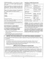
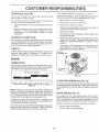
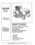
CONGRATULATIONS
on your purchase of a Sears
tractor. It has been designed, engineered and manufactured to give you the best possible dependability and
performance.
PRODUCT
Should you experience any problem you cannot easily
remedy, please contact your nearest Sears Service Center/Department.
We have competent, well-trained technicians and the proper tools to service or repair this tractor.
Please read and retain this manual The instructions will
enable you to assemble and maintain your tractor properly. Always observe the "SAFETY RULES".
MODEL
NUMBER
i
SPECNF CATJONS
HORSEPOWER:
18.0
GASOLINE CAPACITY
AND TYPE:
3.5 GALLONS
UNLEADED REGULAR
OIL TYPE (API-SF/SG):
SAE 30 (above 32°F)
SAE 5W-30 (below 32°F)
OIL CAPACITY:
W/FILTER:
W/O FILTER:
SPARK PLUG:
(GAP: .025")
CHAMPION
EXHAUST:
YOU SHOULD RECORD BOTH SERIAL NUMBER AND
DATE OF PURCHASE AND KEEP IN A SAFE PLACE
FOR FUTURE REFERENCE.
MADNTENANCE
FORWARD:
REVERSE:
AGREEMENT
TIRE PRESSURE:
FRONT:
REAR:
CHARGING SYSTEM:
15 AMPS @3600RPM
BLADE BOLT TORQUE:
30-35 F_. LBS.
Read and observe
the safety
"
Fotlow a regular schedule
using your tractor.
rules.
•
Follow the instructions
under "Customer Responsibilities" and "Storage"
sections of this owner's manual.
in maintaining,
caring for and
LNMITED TWO YEAR WARRANTY
14 PSI
10 PSI
In the state of California the above is required by law
(_Section 4442 of the California Public Resources Code).
Other states may have similar laws. Federal laws apply on
federal lands. A spark arrester for the muffler is available
through your nearest Sears Authorized Service Center
(See REPAIR PARTS section of this manual).
RESPONSIBIMTIES
o
5,6
2.5
WARNaNG:
This tractor is equipped with an internal
combustion engine and should not be used on or near any
unimproved forest-covered, brush-covered or grassocow
ered land unless the engine's exhaust system is equipped
with a spark arrester meeting applicable local or state laws
(if any). If a spark arrester is used, it should be maintained
in effective working order by the operator.
A Sears maintenance
agreement is available on this product, Contact your nearest Sears store for details.
CUSTOMER
.013" - .016"
GROUND SPEED (MPH):
DATE OF PURCHASE
THE MODELAND SERIAL NUMBERS WILL BE FOUND
ON A PLATE UNDER THE SEAT.
RV17YC
tNTAKE:
003"-006"
917,252711
SERIAL
NUMBER
4.0 PINTS
3.5 PINTS
ON CRAFTSMAN
R|DING EQUIPMENT
For two (2) years from the date of purchase, if this Craftsman Riding Equipment is maintained, lubricated and tuned up according
to the instructions in the owner's manual, Sears will repair or replace, free of charge, any parts found to be defective in material
or workmanship.
This Warranty does not cover:
Expendable items which become worn during normal use, such as blades, spark plugs, air cleaners, belts, etc.
,
Fire replacement or repair caused by punctures from outside objects, such as nails, thorns, slumps, or glass.
Repairs necessary because of operator abuse, negligence, improper storage or accident or the faiture to maintain the
equipment according to the instructions contained in the owner's manual.
Riding equipment used for commercial or rental purposes.
LIMITED 90 DAY WARRANTY
ON BATTERY
For ninety (90) days from date of purchase, if any battery included with this riding equipment proves defective in material or
workmanship and our testing determines the battery will not hold a charge, Sears will replace the battery at no charge.
IN-HOME WARRANTY SERVICE ON YOUR CRAFTSMAN RIDING EQUIPMENT IS AVAILABLE AT NO-CHARGE FOR 30
DAYS PROM THE DATE OF PURCHASE.
PLEASE CONTACT YOUR NEAREST SERVICE CENTER. AFTER 30 DAYS
FROM THE DATE OF PURCHASE, WARRANTY SERVICE IS AVAILABLE BY TAKING YOUR CRAFTSMAN RIDING EQUIPMENT TO YOUR NEAREST SEARS SERVICE CENTER. (IN-.HOME WARRANTY SERVICE WILL STILL BE AVAILABLE
AFTER 30 DAYS FROM THE DATE OF PURCHASE BUT A STANDARD TRIP CHARGE WiLL APPLY.) THIS WARRANTY
APPLIES ONLY WHILE THIS PRODUCT IS IN THE UNITED STATES.
This Warranty gives you specific legal rights, and you may also have other rights which may vary from state to state.
SEARS,
ROEBUCK
AND CO., D/817 WA, HOFFMAN
3
ESTATES,
IL 60179
TABLE OF
_AIN_['ENANCE
SERVICE
SC_ED,_J
A_
A_JUST_E_TS
LE
.....................................
...........................
STORAGE
....................................................................
TROUBLESHOOTING
............................................
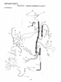
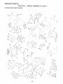
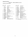
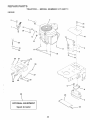
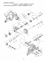
REPAIR PARTS o TRACTOR
.................................
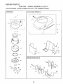
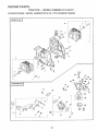
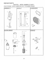
REPAIR PARTS o ENGINE ......................................
PARTS ORDERiNG/SERViCE
................ BACK
17
21
_27
28
29-30
32-49
50-55
COVER
NDE×
A
Accessories ...........................................
5
Adjustments:
Brake .............................................
23
Carburetor ...................................
27
Mower
FrontoTo-Back .......................... 22
Side-To-Side ........................... 22
Throttle Control Cable .................. 27
Air Filter, Engine ..................................
20
Air Screen, Engine ..............................
19
Assembly ..........................................
7-10
IS
Battery:
Charging ........................................
Cleaning .......................................
Starting with Weak Battery ..........
Storage .........................................
Terminals ....................................
Belt:
Motion Drive
Removal/Replacement
...........
Mower Belt(s)
Removal/Replacement
...........
Blade:
Sharpening ..................................
Replacement ................................
Brake Adjustment ................................
8
18
25
28
18
Engine:
Air Filter .......................................
20
Aim"Screen ...................................
19
Cooling Fins .................................. 20
OiI Change ...................................
19
Oil Level ........................................ 19
Oil Type ...................................
14,19
Preparation ................................... 14
Repair Parts ............................ 50-55
Starting .........................................
15
Storage ......................................... 28
F
Filter:
Air Filter ........................................
Fuel ..............................................
Fuel:
Type ............................................
Storage .......................................
Fuse ....................................................
Operation .................................
1I-16
OperaLing Mower ...........................
14
Options:
Accessories ............................
5
Spark Attester ..........................
3,40
P
ParkingBrake .............................
121--13
Parts Bag .................................
6
Parts, Replacement/Repair ............ 32..49
Product Specifications ..........................
3
R
20
20
Repair Parts ...................................
15
28
25
Safety Rules ..........................................
2
Seat ......................................
8
32-49
S
Service and Adjustments ...............
21-27
Carburetor.............................
27
Hood Removaittnstallation ..................
26
Fuse ..................................
26
24
Hood Removatlinstallation ...........
26
Motion Drive Belt
L
23
Removal!Replacement
........... 24.
Leveling Mower Deck .......................... 22
Mower Belt(s)
Lubrication:
18
Remova!/Replacement
........... 23
Chart .............................................
17
18
Mower Adjustment
Engine ........................................... I9
Frontqo-Back ........................... 22
23
Side4o-Side ............................ 22
M
Mower Removal/Installation ......... 21
C
Tire Care ..............................
8,18,28
Maintenance Schedule ....................... 17
Carburetor Adjustment ........................
27
Slope
Guide
Sheet
..........................
59
Mower:
Controls, Tractor ................................
12
Spark
Plug(s)
...............................
20
Adjustment, Front-to-Back ........... 22
Customer Responsibilities ............. 17-20
Adjustment, Sideqo-Side ............. 22
Specifications
...............................
3
Engine:
Blade
Replacement
......................
18
Starting
the
Engine
..........................
!
5
AirFilter
....................................
20
Blade Sharpening ......................
!8
Air Screen ................................
t9
Steering Wheel .............................
7,25
Cutting Height .............................
13
Cooling Fins .............................
20
Stopping the Tractor .........................
!3
Installation
..................................
21
Engine Oil ...........................
14,!9
Operation .....................................
14
Storage....................................
28
Fuel Filter .................................
20
Remova_ ........................................ 21
Spark Plug(s) ...........................
20
Mowing
Tips ........................................
16
T
Tractor:
Muffler ..................................................
20
Battery' ......................................
18
Throttle Control Cable Adjustment ...... 27
Blade.......................................
18
Spark Arrester ...........................
3,40
Tires .............................................
8,18,28
Lubrication Chart .....................
17
Treuble
Shoeting
Chart
.................
29-30
Maintenance Schedule ............ 17
O
Transaxle
..................................
!
9,48-49
TireCare .........................
8,18,28
Oil:
Transaxle.................................
19
Cold Weather Conditions ........ 13,t9
W
Cutting Height, Mower ........................ 13
Engine ..........................................
19
Warranty...................................
3
Storage .......................................
28
E
WiringDiagram .............................
32
Electrical:
Wiring Schematic ................................ 31
Interiocks and Relays .................. 26
Schematic ...............................
31
WiringDiagram ............................
32
H
4
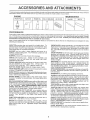
ACCESSOR!
AND ATTACH
These accessories and attachments were available through most Sears retail outlets and service centers when the tractor was purchased,
Most Sears stores can order these items for you when you provide the model number of your tractor.
ENGINE
SPARK PLUG
MAaNTENANCE
GAS CAN
ENGINE OIL
FUEL STABILIZER
A_RFILTER
8LADES
BELTS
PERFORMANCE
Sears offers a wide variety of attachments that fit your tractor.
you. This list was current at the time of publication; however,
may be made in these attachments, or some may no longer
accessories and attachments
that are available for your
Most of these attachments
attaching and detaching.
Many of these are listed below with brief explanations of how they can help
it may change in future years - more attachments may be added, changes
be available or fit your model. Contact your nearest Bears store for the
tractor.
do not require additional hitches or conversion
AERATOR promotes deep root growth for a healthy lawn. Tapered 2.54nch steel spikes mounted on !0-inch diameter discs
puncture holes in soil at close intervals to let moisture soak in.
Steel weight tray for increased penetration.
BAGGER lets you collect
grass clippings and leaves for a
heaffhier, nearer looking lawn. Two Permanex containers hold
30-gallon plastic bags.
BUMPER protects front end of tractor from damage.
CARTS make hauling easy. Variety of sizes available, plus
accessories such as side panel kits, tool caddy, cart cover,
protective mat and dolly.
CORING AERATOR takes small plugs out of soi! to allow moisture and nutrients to reach grass root& 36-inch swath. 24
hardened steel coring tips. 150 lb. capacity weight tray.
EASY OIL DRAIN VALVE makes oil changes easier, faster.
FRONT NOSE ROLLER canters in front of mower deck to reduce
chances of "scalping" on uneven terrain.
GANG HITCH lets you tow 2 or 3 pull-behind attachments at once,
such as sweepers, dethatchers, aerators (not for use with rollers,
carts or other heavy attachments).
GAUGE WHEELS on both sides of the mower deck reduce
chances of "scalping" on uneven terrain. For mower decks not so
equipped.
MULCH RAKE/DETHATCHER
loosens soil and flips thatch and
matted leaves to lawn surface for easy pickup. Twenty spring tine
teeth. Useful to prepare bare areas for seeding. Available for front
or rear mounting.
HIGH PERFORMANCE
REEL-ACTION
SPRING "FINE DETHATCHER covers 36-inch wide path and
tosses thatch into large hopper. Mounts behind tractor.
MULCHING CLOSE-OUT PLATE KiT, once installed, lets you
mulch, discharge or bag clippings (bagger optional) without
changing blades. For models not equipped as 34nol Convertible
mowers.
See "MOWER" in the Repair Parts section of this
manual.
RAMP TOPS AND FEET let you load and unload tractor from a
pickup truck. Use with 2 x 8 or 2 x 10 lumber.
ROLLER for smoother lawn surface.
36-inch wide, 18-inch
diameterwater-tight
drum holds up to 390 Ib& of weighL Rounded
edges prevent harm to tud° Adjustable scraper automatically
cleans drum.
kits (those that do are indicated) and are designed for easy
SNOW BLADE for snow removal only. 14qnch high, 48qnch wide
blade clears 42-inch path when angled left or right. Raises, lowers
with side lever. Adjustable skids; repJaceable, reversible scrape[
bar. (Use with tire chains and wheel weights and/or rear drawbar
weight.)
SNOWTHROWER has 40-inch swath. Drum-type auger handles
powdery and wet/heavy snow. Mounts easily with simple pin
arrangement. Discharge chute adjusts from tractor seat. 6-inch
diameter spout discharges snow 10 to 50 feet. Lift controlled at
tractor seat. (Use with chains and wheel weights and/or rear
drawbar weight.)
SPRAYERS use 12-volt DC electric motor that connects to the
tractor battery or other 12-volt source.
Includes booms for
automatic spraying and hand held wand for spot spraying. Wand
has adjustable spray pattern. For applying herbicides, insecticides, fungicides and liquid fertilizers.
SPREADER/SEEDERS
make seeding, fertilizing, and weed killing easy. Broadcast spreaders are also useful for granular deicers and sand.
SWEEPERS let you collect grass clippings and leaves.
TILLER has 5 hp engine and 36-inch swath to prepare seed beds,
cultivate and compost garden residue. Tiller has its own built-in
lift and depth control system and does NOT require a sleeve hitch,
Fits any lawn, yard or garden tractor. Simply hook up to the tractor
drawbar and go!
Optional
accessories
convert unit for
dethatching, aerating, hilling,..without tools.
TiRE CHAINS are heavy duty; closely spaced extra-large cross
links give smooth ride, outstanding traction.
TRACTOR CAB has heavy duty vinyl fabric over tubular steel
frame, ABS plastic top; clear plastic windshield offers 360 degree
visibility. Hinged metal doors with catch. Keeps operator warm
and dry. Remove vinyl sides and windshields for use as sun
protector in summer. Optional accessories
include: tinted/
tempered solid safety glass windshield with hand operated wiper;
12-volt amber caution light for mounting on cab top.
VACS for powerful collection of heavy grass clippings and leaves=
Optional wand attachment to pick up debris in hard-to-reach
places. VAC/CHIPPER includes a chipper-shredder.
WEIGHT BRACKET for drawbar for snow removal applications.
Uses (1) 55 lb. weight.
WHEEL WEIGHTS for rear wheels provide needed traction for
snow removal or dozing heavy materials.
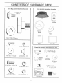
CONTE
Parts Bag contents
rl
F
shown
fu_ size
Parts packed
separately
in carton
(1) Shoulder Bolt
q
5/16 t8
Seat
Video
Cassette
i/
(1) Knob
Steering
Whee!
Mulcher
Plate
(!) Washer
17/32 x 1-3/16 x t2 Gauge
..........................
@
(2) Screws #!0 x 5/8
(2) Lock Washers
I
Manual
Parts Bag
#10
Parts bag contents
_._
(2) Washers
3/16 x 3/4 x 16 Gauge
full size
x(2)7/8
Washers
x t4 Gauge
3/8
(2) Shoulder
Bolts
(2) Weld Nuts #10
(2) CenteF
lock Nuts
@
(2) Hex Nuts 1/420
9/32 x 5/8 x "t6 Ga.
not shown
___(_
Steering
Wheel
insert
(2) Hex Bolts t/4-20 x 3/4
t
(2) Lock Washers
(2) Keys
_-(2)
\
\
(2) Gauge
Wheels
L.atch Hook
Assembty
Steering
Sleeve
1/,4
Slope Sheet
BLY
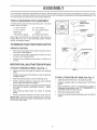
Your new tractor has been assembled at the factory with exception of those parts left unassembted for shipping purposes
To ensure safe and proper operation of your tractor, all parts and hardware you assemble must be tightened securely. Us_
the correct tools as necessary to insure proper tightness.
TOOLS
REQUIRED
FOR ASSE_BLY
-._. _
A socket wrench set will make assembly easier. Standard
wrench sizes are listed.
(1) 9/!6" wrench
(1) 1/2" wrench
Utility knife
(2) 7/16" wrench
(1) :-}/4"socket w/drive
ratchet
Tire pressure gauge
(1) Phillips Screwdriver
WHEEL
INSERT
_/LOCKNUT
i
_ LARGE FLAT
,,: :_..,..I WASRER
WHEEL
When right and left hand is mentioned in this manual, it
means when you are in the operating position (seated
behind the steering wheel).
TO REMOVE TRACTOR
UNPACK
FROM CARTON
CARTON
STEERING
WHEEL
ADAPTER
Remove all accessible loose parts and parts cartons
from carton (See page 6).
Check for any additional
remove.
_,_f'
# STEERING
1 /
<_._/
/"
/STEERING
SLEEVE
/
BEFORE ROLLING TRACTOR OFF SKID
/_S
I
/
/ 1
_'/
I
/
WHEEL
(See
Fig. 1)
I'"
/
/
i//
'- _ ._ I/
STEERING
,
loose parts or cartons and
/
ATTACH
SHAFT
/
/,_v
Cut, from top to bottom, along lines on all four corners
of carton, and lay panels flat.
•
_..._d_,
/
J/
FIG, t
,
Remove locknut and large fiat washer from steering
shaft.
•
Position front wheels of the tractor so they are pointing
straight forward.
-
Slide the steering sleeve over the steering shaft.
o
Position steering wheel so cross bars are horizontal
(left to right) and slide onto adapter.
,
o
Secure steering wheel to steering shaft with Iocknut
and large flat washer previously removed. Tighten
securely.
Release parking brake by depressing
pedal.
-
,
Snap steering
wheel.
Place freewheel control in freewheeling position to
disengage transmission (See "TO TRANSPORT" in
Operation section of this manual).
Roll tractor backwards off skid.
wheel insert into center of steering
,
Remove protective
plastic from tractor hood and grill.
IMPORTANT:
CHECK FOR AND REMOVE ANY STAPLES
IN SKID THAT MAY PUNCTURE TIRES WHERE TRACTOR
IS TO ROLL OFF SKID.
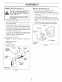
TO ROLL TRACTOR
OFF SKID (See Fig, 7)
Raise attachment lift lever to its highest position.
clutch/brake
Remove banding holding discharge guard up against
tractor.
E
CONNECT
BATTERY
(See Fig. 2)
INSTALL
CAUTION: Do not short battery terminals° Before connecting
battery, remove metal braceaets,
wristwatch
bands_ rings, etc°
Positive termina_ must
first to prevent sparking
tal grounding.
be connected
from accideno
Lift hood to raised position.
,
Open terminal access doors, remove terminal protective caps and discard.
If this battery is put into service after month and year
indicated on labe[ ([abe[ located between terminals)
charge battery for minimum of one hour at 6o10 amps.
First connect RED battery cable to positive (+.)battery
terminal with hex bolt, fial washer, lock washer and hex
nut as shown. Tighten securely_
o
LY
Connect BLACK grounding cable to negative (_) battery termina! with remaining hex boIt, flat washer, lock
washer and hex nut. Tighten securely.
Ctose terminal access door&
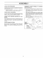
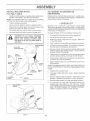
SEAT (See Fig. 3}
Adjust seat before tightening adjustment knob.
o
Remove cardboard packing on seat pan.
Ptace seat on seat pan and assemble shoulder bolt.
o Assemble adjustment knob and fiat washer loosely.
Do not tighten°
Tighten shoulde__bolt secL_rely.
Lower seat into operating position and sit on seat.
o Slide seat until a comfortable position is reached which
allows you 1o press clutch/brake pedal all the way
down.
Get off seat without moving its adiusted position.
Raise seat and tighten adjustment knob securely.
SEAT
SEAT PAN
SHOULDER
BOLT
Use terminal access doors for:
•
Inspection for secure connections
ware).
(to tighten hard_
FLAT WASHER
Inspection for corrosion.
o
ADJUSTMENT
KNOB
Testing battery.
Jumping (if required).
o
FroG.3
Periodic charging.
DISCARD
TERMINAL
PROTECTIVE
CAPS
HEX NUT
LOCK
WASHER
FLAT
WASHER
BEX
POSiTiVE
(RED)
CABLE
NEGATIVE
(BLACK)
CABLE
VENT HOLE
(KEEP CLEAN)
F_Go2
CHECK
T_RE PRESSURE
ASSEMBLE
The tires on your tractor were overinflated at the factory for
shipping purposes. Correct tire pressure is important for
best cutting performance°
DECK
FOR
POSITION
•
With mower in desired height of cut position, gauge
wheels should be assembled so they are slightly off the
ground. Install gauge wheel in appropriate hote with
shoulder bolt, 3/8 washer, and 3/8-16 Iocknut and
tighten securely.
Repeat for opposite side installing gauge wheel in
same adjustment hole.
OF ALL
See the figures that are shown for replacing motion and
mower blade drive belts in the Service and Adjustments
section of this manual. Verify that the belts are routed
correctly.
CHECK
BRAKE
MOWER:
Adjust mower to desired cutting height (See "TO AD.
JUST MOWER CU_q-tNG HEIGHT" in the Operation
section of this manual).
LEVELNESS
PROPER
TO
DECK (See Fig. 4,)
For best cutting results, mower housing should be properly
leveled. See "TO LEVEL MOWER HOUSING" in the
Service and Adjustments section of this manual
CHECK
BELTS
WHEELS
Assemble gauge wheels with tractor on a fiat level surface.
Reduce tire pressure to PSi shown in "PRODUCT
SPECIFICATIONS" on page 3 of this manual.
CHECK
GAUGE
SYSTEM
After you learn how to operate your tractor, check to see
that the brake is properly adjusted. See '"TO ADJUST
BRAKE" in the Service and Adjustments section of this
manual.
BRACKET
LOCKNUT
GAUGE
FIG, 4
9
iNSTALL MULCHER PLATE
TO CONVERt
DISCHARGING
(See Figs° 5 and 6)
Install two latch hooks to muicher plate using screw,
washer, lock washer, and weld nut as shown.
NOTE: Preoassembte weld nut to latch hook by inserting
weld nut from the top with hook pointing down.
o Tighten hardware securely,
Raise and hold deflector shield in upright position,
Place front of mulcher plate ever front of mower deck
opening and slide into place, as shown.
o Hook front latch into hole on front of mower deck,
Hook rear latch into hole on back of mower deck.
BEFC)RE YOU OPEFAtATE AND ENJOY YOUR NEW
TRACTOR, WE VVfSH 710ASSURE %HAT YOU RECEIV_
THE BEST PERFORMANCE AND SA T?SFACTION FROM
THIS QUALITY PRODUC7:
PL.E;ASE REWEW THE FOLLOWING CHECKLIST7
/
A!l assembly instructions have been completed.
and hold
/
No remaining loose parts in carton.
plate
i
Battery is properly prepared and charged.
t hour at 6 arRps).
l
Seat is adjusted comfortably and tightened securely.
i
All tiros are properly inflated. (For shipping purposes,
the tires were overinflated at the factory).
t
Be sure mower deck is properly leveled side-to-side/
frontqo-rear for best cutting results. (Tires must be
properly inflated for leveling).
/
Check mower and drive belts. Be sure they are routed
properly around pulleys and inside all belt keepers
i
Check wiring. See that all connections are still secure
and wires are properly clamped.
/
Before driving tractor, be sure freewheel control is in
drive position.
I __"
_e_n
operaf_ion
\
HOOK
LOCK
WASHER
WELD
NUT
\
/
Engine oil is at proper leve!.
,Z
Fue! tank is filled wiIh fresh, clean, regular unleaded
gasoline.
Become familiar with all controls -- their !ocation and
function. Operate them before you star1 the engine.
¢
V" Be sure brake system is in safe operating condition.
FIG. 5
V"
DEFLECTOR
SHIELD
/
f
\
\\
LATCH
HOOKS
F_G.e
(Minimum
WHILE LEARNING HOWTO USE YOUR TRACTOR, PA Y
E:XTRA A TTEN770N 70 XNE FOLLOWING IMPORTANT
/7-E?_¢S:
WASHER
MULCHER
PLATE
OR
Simply remove mulcher plate and store in a safe place.
Your mower is now ready for discharging or instaftation of
optional grass catcher accessory°
o
[_se
TO BAGGING
I0
it is important to purge the transmission before you
operate your new tractor for the first time
Fo!low
proper starting and transmission purging instructions
(See "TO START ENGINE" and "PURGE TRANSMIS-SION" in Operation section of this manual).
P
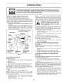
These symbols may appear on your tractor or in literature supplied with the product, Learn and understand their meanin!,
BATTERY
CAUTION OR
WARNING
REVERSE
FORWARD
FAST
SLOW
ENGINE ON
ENGINE OFF
OIL PRESSURE
CLUTCH
LIGHTS ON
LIGHTS OFF
MOWER HEIGHT
DIFFERENTIAL
LOCK
PARKING BRAKE
LOCKED
UNLOCKED
IX
FUEL
CHOKE
L
REVERSE
MOWER LIFT
NEUTRAL
ATTACHMENT
CLUTCH ENGAGED
HIGH
LOW
PARKING BRAKE
ATTACHMENT
CLUTCH DISENGAGED
HYDROSTATIC
DANGER, KEEP HANDS AND FEET AWAY
IGNmON
FREE WHEEL
(Hydro Modeis onBy)
11
KNOW YOUR TRAC fOR
READ
TH_S OWNER°S
MANUAL
AND
SAFE°_
RULES
BEFORE
OPERAT#_G
YOUR
TRACTOR
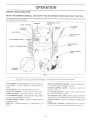
Compare the illustrations with your tractor to familiarize yourself with the bcatiens of var ous controls and adjustments.
this manual for future reference.
AMMETER
CHOKE
ATTACHMENT
SWITCR
CONTROL,
" ............
Save
CLU T'CH
"
L_FT LEVER
THROTTLE
CONTROL
PLUNGER
UGRT SW_TOR
ATTACHMENT
LEVER
PARKING
LEVER
UF'°[
RRAXE
MOTION CONTROL
LEVER
FREEWHEEL
CONTROL
F_G°7
Our tractors cenforrn to the safety standards of the American National Standards tr slitute.
ATTACHMENT CLUTCH SWITCH: Used to engage the
mower blades, or other attachrTents mounted to your
tractoL
L_GRT SW_TCH: Turns the headiights on and ell
TRROTTLE CONTROL: Used to centre', engine speed
CHOKE CONTROL: Used when starting a cold engine.
CLUTCNiBRAKE PEDAL: Used for deciutching and brak o
ing the tractor and starting the engine.
PARKING BRAKE LEVER: Locks clutch/brake pedal into
[he brake position°
A_'vIB#E7EB: Indicates charging (+) or dischargi_ 9 (-) of
HEIGHT ADJUST_,qENT KNOB: Used to release attachmen_ lift lever when changing its position,
B_OT_ON CONTROL
direction of tractor.
LEVER:
Selects the speed and
LIFT LEVER PLUNGER: Used to release attachment tift
lever when changir_g its position.
ATTACRf_'_ENT UFT LEVER: Used to raise and tower the
mower deck or other attachments mounted to your tracbr.
IGNiTiON
SWI[CR:
Used for starting and stopping the
FREEWHEEL CONTROL: Disengages trans_:ssien [or
pushir g.or siowty towing the tractor with ",n_...
en,_ine, off.
PE
The operation of any tractor can resuRt in foreign objects thrown into the eyes, which can
result in severe eye damage. A_ways wear safety glasses or eye shietds while operating
your tractor or performing any adjustments or repairs. We recommend a wide vision safety
mask over the spectacles or standard safety glasses.
HOW TO USE YOUR TRACTOR
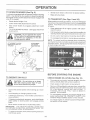
TO SET PARKING
BRAKE
NOTE: Under certain conditions when tractor is standinf:_
idle with the engine running, hot engine exhaust gases may
cause "browning" ol grass. To eliminate this possibility,
always stop engine when stopping tractor on grass areas
(See Fig. 8)
Your tractor is equipped with an operator presence sensing
switch. When engine is running, any attempt by the
operator to leave the seat without first setting the parking
brake will shut off the engine.
Depress clutch/brake pedal into full "BRAKE" position
and hold.
o
Place parking brake lever in "ENGAGED" position and
release pressure from clutch/brake pedal Pedalshould
remain in "BRAKE" position. Make sure parking brake
will hold vehicle secure.
CAUTWON: Always stop tractor como
pletely, as described above, before leavo
ing the operator's position; to empty
grass catcher, etc.
TO USE THROTTLE
CONTROL
(See Fig. 8)
Always operate engine at full throttteo
•
Operating engine at less than full throttle reduces the
battery charging rate.
o Full throttle offers the best bagging and mower peffor.
mance.
ATTACHMENT CLUTCH SWITCH
PULL OUT TO "ENGAGE"
IGNITION KEY
PUSH4NTO
"DISENGAGE"
CHOKE
CONTROL
TO USE CHOKE
CONTROL
(See Fig. 8)
Use choke control whenever you are starting a cold engine
Do not use to start a warm engine.
o To engage choke control, pull knob out. Slowly push
knob in to disengage.
TO MOVE FORWARD
(See Fig, 8)
AND BACKWARD
The direction and speed of movement is controlled by the
motion contro! lever.
•
CLUTCH/BRAKE
PEDAL"DRIVE"
POSITION
PARKING
HEIGHT
ADJUSTMENT
KNOB
BRAKE
•
"DISENGAGED"
POSITION
TO ADJUST
(See Fig. 8)
FIG. 8
STOPPING
,
,
-
THE
MOTION
CONTROL
LEVER
DOES
NOT RETURN TO NEUTRAL (N) POSITION WHEN THE
CLUTCH/BRAKE PEDAL IS DEPRESSED.
ENGINE o
Move throttle control to stow (_)
position.
NOTE: Failure to move throttle control to slow (_)
position and allowing engine to idle before stopping may
cause engine to "backfire".
o Turn ignition key to "OFF" position and remove key.
Always remove key when leaving tractor to prevent
unauthorized use.
,_
CUTTING
HEIGHT
Turn knob clockwise (f_) to raise cutting height.
Turn knob counterclockwise (_)to
lower cutting
height.
The cutting height range is approximately 1_1/2" to 4". The
heights are measured from the ground to the blade tip with
the engine not running. These heights are approximate
and may vary depending upon soil conditions, height of
grass and types of grass being mowed.
The average lawn should be cut to approximately 2-1/2
inches during the cool season and to over 3 inches
during hot months. For healthier and better looking
lawns, mow often and after moderate growth.
For best cutting performance, grass over 6 inches in
height should be mowed twice. Make the first cut
relatively high; the secorld to desired height°
clutch switch to "DISENGAGED"
Depress clutch!brake pedal into full "BRAKE" position.
Move motion control lever to neutral (N) position.
IMPOFtTANT:
MOWER
The cutting height is controlled by turning the height adjustment knob in desired direction.
(See Fig. 8)
MOWER BLADES Move attachment
position.
GROUND DRIVE -
Start tractor with motion control lever in neutral (N)
position.
Release parking brake and clutch/brake pedal.
Slowly move motion control lever to desired position.
Never use choke to stop engine.
13
TO OPERATE
MOWER
(See
Fig. 9)
Slowly move motion control lever to slowest setting°
'_our tractor is equipped with an operator presence sensing
switch. Any attempt by the operator to leave the seat with
the engine running and the attachment clutch engaged will
shut off the engine_
o
o
o
When pushing or towing your tractor, be sure to disengage
transmission by placing treewhee! controf in freewheeling
position. Free wheet centre! is located at the rear drawbar
of tractor.
Make all turns slowly.
TO TRANSPORT
Select desired height of cut.
Lower mower with attachment [ift control.
Start mower blades by engaging attachmen_ clutch
control.
TO STOP MOWER BLADES _ disengage attachment
clutch controk
(See Figs. 9 and t0}
o
Raise attachment
ment lift control
Jift to highest position with attach-
o
Pu!l freewheel contro[ knob out and hold in position by
inserting retainer spring into fowvard hole of control rod.
Do not push or tow tractor al more than two (2) MPH.
o
To reengage transmission,
reverse above procedure
NOTE: To protect hood from damage when transporting
your tractor ORa truck or a _railer, be sure hood is closed and
secured totractor. Use an appropriate means of tying hood
to tractor (rope, cord, etc.)_
ATTAC_4MENT
L_F'T LEVER
HIGH POSmON
LOW
/
DISCHARGE
GUARD
FIG. 10
[ ....
FiG. g
BEFORE
TO OPERATE
ON HILLS
CHECK
STARTING
ENGINE
THE ENGINE
OIL LEVEL
(See Fig, 16)
The engine in your tractor has been shipped, from the
factory, already filled with summer weight oil.
Check engine oil with tractor ORlevel ground
o
Choose the slowest speed before starting up or down
hills°
o
Avoid stopping or changing speed on hills.
[f slowing is necessary,
slower position.
o
Remove oil fill cap/dipstick and wipe clean, reinse_t the
dipstick and push it all the way down into the tube, wait
for a few seconds, remove and read oii levek Jf
necessary, add oil until "FULL" mark on dipstick is
reached. Do not overfi[k
move throttle control lever to
if stopping is absoJutely necessary, push clutch/brake
pedal quickly to brake position and engage parking
brake.
Move motion control lever to neutral (N) position.
iMPORTANT:
THE MOTION CONTROL LEVER DOES
NOT RETURN TO NEUTRAL (N) POSFTION WHEN THE
CLUTCH!BRAKE PEDAl__IS DEPRESSED.
°
TO resta_!:movement, slowly release parking brake and
clutch/brake pedal
14
o
For cold weather operation you should change oil for
easier slatting (See "OIL VISCOSITY CHART" in the
Customer Responsibilities section of this manual).
o
To change enghe oil, see the Customer Responsibifi_
ties section in this manual.
OPERATION
ADD GASOUNE
PURGE TRANSMISSION
o
Fill fuel tank.
Use fresh, clean, regular unleaded
gasoline. (Useof leaded gasolinewill
increasecarbon
and lead oxide deposits and reduce valve life).
mMPORTANT:
WHEN OPERATING
IN TEMPERATURES
BELOW32°F(0°C),
USE FRESH, CLEAN WINTER GRADE
GASOLINE
TO HELP INSURE GOOD COLD WEATHER
STARTING.
&
o
,
Sitting in the tractor seat, start engine. After the engine
is running, move throttle control to slow (,,_) position.
With motion control lever in neutral (N) position, slowly
disengage clutch/brake pedal.
,
Move motion control lever to full forward position and
hold for five (5) seconds. Move lever to full reverse
position and hold for five (5) seconds. Repeat this
procedure three (3) times.
(See Fig. 8)
When starting engine for the first time or if engine has run
out of fuel, it will take extra cranking time to move fue! from
the tank to the engine.
Depress clutch/brake
NOTE: During this procedure there will be no movement of
drive wheels. The air is being removed from hydraulic drive
system.
pedal and set parking brake.
Place motion control lever in neutral (N) position.
o
Move attachment clutch to "DISENGAGED"
o
Pull choke control out to choke (!\1)position for cold
engine start. For warm engine start do not use choke
control.
position.
Move throttle control to midway between fast (_)
stow (_)
positions.
o
Move motion control lever to neutral (N) position. Shut
off engine and set parking brake.
,
Engage transmission by placing freewheel control in
driving position (See "TO TRANSPORT" in this section
of manual).
,
Sitting in the tractor seat, start engine. After the engine
is running, move throttle control to half (1/2) speed
With motion control lever in neutral (N) position, slowly
disengage clutch/brake pedal.
*
Slowly move motion control lever forward, after the
tractor moves approximately five (5) feet, slowly move
motion control lever to reverse position. After the
tractor moves approximately five (5) feet return the
motion control lever to the neutral (N) position. Repeat
this procedure with the motion control lever three (3)
times.
and
Insert key into ignition and turn key clockwise to "START"
position and release key as soon as engine starts. Do
not run starter continuously for more than fifteen
seconds per minute. If engine does not start after
several al_empts, move throttle control to Past (@)
position, wait a few minutes and try again.
*
When engine starts, slowly push choke control in.
®
Move throttle control to fast (,¢_) position.
Place tractor safely on level surface with engine off and
parking brake set.
Disengage transmission by placing freewheel contro
in freewheeling position (See "TO TRANSPORT" i_'
this section of manual).
filler neck. Do not overfill. Wipe off any
CAUTION:
bottom
of gas
spilled
oil or Fill
fuet.to Do
not store,
spilltank
or
use gasoline near an open flame.
ENGmNE
:_
To ensure proper operation and performance, it is recorr
mended that the transmission be purged before operatin!:!
tractor for the first time. This procedure wilt remove any
trapped air inside the transmission which may have deveioped during shipping of your tractor.
IMPORTANT: SHOULD YOUR TRANSMISSION REQUIRL
REMOVAL FOR SERVICE OR REPLACEMENT.
!
SHOULD BE PURGED AFTER REtNSTALLATiON
BEFORE OPERATING THE TRACTOR.
WARNING:
Experience indicates that atcohot blended
fuels (called gasohol or using ethanol or methanol) can
attract moisture which leads to separation and formation of
acids during storage. Acidic gas can damage the fuel
system of an engine while in storage. To avoid engine
problems, the fuel system should be emptied before stoF
age of 30 days or longer. Drain the gas tank, start the
engine and let it run until the fuel lines and carburetor are
empty. Use fresh fuel next season. See Storage Instructions for additional information.
Never use engine or
carburetor cleaner products in the fue! tank or permanent
damage may occur.
TO START
freewhee_ _ever whi_e the engine is runCAUT!ON:
Neverengageordisengage
nit,
go
Your tractor is now purged and now ready for normai
operation.
o
Allow engine to warm up for a few minutes before
engaging drive or attachments.
IMPORTANT: COLD STARTING FOR HYDRO (BELOW
40°F)
- AFTER
STARTING ENGINE AND BEFORE
DRIVING, LET TRANSMISSION WARM UP FOR ONE (1)
MINUTE BY PLACING MOTION CONTROL LEVER IN
NEUTRAL (N) POSITION AND RELEASING CLUTCH/
BRAKE PEDAL.
NOTE: If at a high altitude (above 3000 feet) or in cold
temperatures (below 32°F), the carburetor fuel mixture
may need to be adjusted for best engine performance. See
"TO ADJUST CARBURETOR" in the Service and Adjustments section of this manual.
15
t OW NG
T PS
MULCHING
o
•
•
TNPS
_MPORTANT':
FOR BEG"[ PERFORMANCE,
KEEP
MOWER HOUSING FREE OF BUILT-.UP GRASS AND
TRASH. CLEAN AFTER EACH USE.
Tire chains cannot be used when the mower housing
is attached to tractor.
o
MOWING
Mower should be properly leveled for best mowing
performance. See "TO LEVEL MOWER HOUSING" in
the Service and Adjustments section of this manual.
The left hand side of mower should be used for trimruing.
-[he special muiching blade will recut the grass clip °
pings many times and reduce them in size so that as
they fall onto the lawn they wilt disperse into the grass
and not be noticed. Atso, the mutched grass will
biodegrade quickly to provide nutrients for the !awn.
Always mulch with your highest engine (b!ade) speed
as this will provide the best recutting action of the
blades.
Drive so that clippings are discharged onto the area
that has been cut. Have the cut area to the right of the
rnaehine. This will resu!t in a more even distribution d
clippings and mere uniform cutting,,
o
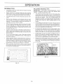
When mowing large areas, start by turning to the right
so that clippings will discharge away from shrubs,
fences, dnveways, etc. After one or two rounds, mow
in the opposite direction making left hand turns until
finished (See Fig, 11 ).
Avoid cutting your lawn when it is wet. Wet grasstends
to form clumps and interferes with the muJchhlg action.
The best time to mow your lawn is the early afternoon.
At this time the grass has dried and the newly cut area
will not be exposed to [he direct sun.
o
If grass is extrernely tall, it should be mowed twice to
reduce load and possibte fire hazard from dried clipo
pings. Make first cut relatively high; the second to the
desired height.
For best results, adjust the mower cutting height sothat
the mower cuts off only the top one4hird of the grass
blades (See Fig. 12). For extremely heavy mulching,
reduce your width of cut on each pass arid mow slowly.
o
Certain types of grass and grass conditions may require that an area be mulched a second time to completely hide the ciippings. When doing a second cut,
mow across or perpendicular to the first cut path.
o
Change your cutting pattern from week to week, Mow
north to south one week then change to east to west the
ne_ week, This wilJ help prevent matting and graining
of the lawn.
Do net mow grass when it is wet, Wet grass will plug
mower and leave undesirable clumps. Allow grass io
dry before mowing.
Always operate engine at full throttle when mowing to
assure better mowing performance and proper discharge of material. Regulate ground speed by select o
ing a low enough gear to give the mower cutting
performance as well as the quality of cut desired.
When operating attachments, select a ground speed
that will suit the terrain and give best performance of
the attachment being used°
F_Go12
(
,F_Go1 t
16
CU
LINES
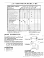
MAINTENANCE
SCHEDULE
FILL iN DATES
AS YOU COMPLETE
REGULAR SERVICE
TI
Rt
A
C
T
0
R
SERVUCE DATES
Check
Brake Operation
Check
Tire Pressure
Cheek for Loose Fasteners
Sharpen/Replace
Lubrication
Check
Mower
Blades
Chart
Battery, Level/Recharge
Clean Battery and Terminals
Check
Transaxle
Adjust
Blade Belt(s) Tension
Adjust
Motion Drive Belt(s) Tension
Check
Engine
Change
E_
NI.
G
l
N
E
Cooling
Oil Level
Engine Oil
ti2
Clean
Air Filter
Clean
Air Screen
Inspect
Muffler/Spark
Replace
Clean
Arrester
Oil Filter (If equipped)
Engine Cooling
Fins
ti
Replace
Spark Plug
Replace
Air Filter Paper Cartridge
Replace
Fuel Filter
v'
w
1 _ Change
more
often
when
2 - Service
more
often
when
3 - If equipped
4 _ Replace
GENERAL
with
blades
oil filter,
more
operating
operating
change
often
when
under
in dirty
e heav'
or dusty
oil every
50 hours.
mowing
in sandy
load or in high
ambient
temperatures.
5 _ If equipped
conditions.
with
6 - Not required
7 - Tighten
soil.
adjustable
if equipped
front axle pivot
system.
with
maintenance-free
bolt to 35 ft.-Ibs,
battery.
maximum.
Do not overtighten.
RECOMMENDATIONS
LUBRICATION
The warranty on this tractor does not cover items that have
been subjected to operator abuse or negligence,
To
receive full value from the warranty, operator must maintain
tractor as instructed in this manual.
(_)SPINDLE
CHART
ZERK_f..._.-
SP,NDLE
ZERK(_
F,ONTWNEEL@
Some adjustments will need to be made periodically to
properly maintain your tractor.
REARINGZERK _
I
_
_2# REARINGZERK
All adjustments in the Service and Adjustments section of
this manual should be checked at least once each season.
®
Once a year you should replace the spark plug, clean
or replace air filter, and check blades and belts for
wear. A new spark plug and clean air fitter assure
proper air-fuel mixture and help your engine run better
and last longer.
BEFORE
EACH
®
CLUTCH PIVOT
USE
Check engine oi! level.
o
Check brake operation.
o
Check tire pressure.
Check for Hoose fasteners,
_SAE
30 MOTOR OIL
(_GENERAL
(_F_EFER
PURPOSE
GREASE
TO CUSTOMER
RESPONStB_UTBES
"ENGINE"
SECTION
IN_PORTANT:
DO NOT OIL OR GREASE THE PfVOTPOiNTS,
WHICH HAVE SPECIAL NYLON BEARINGS.
VISCOUS LUBRiCANTS W_LL ATTRACT
DUST AND DRT THAT WILL SHORTEN
THE LiFE OF THE SELF-LUBRICATING
BEARINGS,
iF YOU
FEEL THEY MUST BE LUBRICATED,
USE ONLY A DRY, PQW_
17
DERED
GRAPHITE
TYPE
LUBRICANT
SPARINGLY,
CU
E
ES
TRACTOR
TO SHARPEN
Always observe safety rules when performing any maintenance.
Care should be taken to keep the blade balanced. An
unbalanced blade will cause excessive vibration and even°
tual damage to mower and engine.
BRAKE
OPERATION
tf tractor requires more than six (6) feet stopping distance
at hgh speed in highest gear, then brake must be adjusted.
(See "TO ADJUST BRAKE" in the Service and Ad}ustments section of this manua0.
o
BLADE
NOTE: Do not use a nail for balancing blade. The lobes of
the center' hole may appear to be centered, but are not.
CARE
For best results mower blades must be kept sharp.
place bent or damaged blades.
BLADE
To check blade balance, you witI need a 5/8" diameter
steel bolt, pin, or a cone balancer. (When using a cone
balancer, fol!ow the instructions supplied with bar
Slide blade on to an unthreaded portion of the stee! bolt
or pin and hold the bo!t or pin parailel with the ground.
If blade is balanced, it should remain in a horizontal
position, If either end of the blade moves downward,
sharpen the heavy end _ntil the blade is balanced.
Keep tires free of gasoline, oil, or insect control chemicals which can harm rubber.
Avoid stumps, stones, deep ruts, sharp objects and
other hazards that may cause tire damage.
(See Fig. 14)
The blade can be sharpened with a file or on a grinding
wheel. Do not attempt to sharpen while on the mower,
Maintain proper air pressure in all tires (See "PROD-.
UCT SPECIFICATIONS" on page 3 of this manual).
o
BLADE
REMOVAL
(See
Fig.
Re518" BOLT
OR PMN
13}
o
Raise mower to highesf position to allow access to
blades.
°
Removehexbolt,
blade.
o
Install new or resharpened blade with trailing edge up
towards deck as shown.
o
Reassemble hex bolt, lock washer and flat washer in
exact order as shown.
lockwasherandflatwashersecuring
Tighten bolt securely (30.G5 Ft° Lbs. torque).
_&'_PORTANT: BLADE BOLT IS GRADE 8 HEAT'TREATED.
NOTE: We do not recommend sharpening blade- but if you
do, be sure the blade is balanced.
MANDREL
ASSEMBLY
BLADE
\
BLADE
FIGo 14
BATTERY
Your tractor has a battery charging system which is su[fi,,
cient for normal use. However, periodic charging of the
battery with an automotive charger wi!l extend its life,
o
Keep battery and terminals clean_
o
Keep battery bolts tight.
o
Keep smaN vent holes open (See "CONNECT BAT-.
TERY" in the Assembly section of this manual).
•
Recharge at 6 amperes for t hour.
TO CLEAN BATTERY AND TERMINALS
Corrosion and dirt on the battery and terminals can cause
the battery to "leak" power.
FLAT WASHER
o
LOCK WASHE_
Open battery box door..
Disconnect BLACK battery cable first then RED battery cable and remove battery frem tractor,
o
Wash battery with solution ot four tablespoons of
baking soda to one gallon of water. Be careful not to get
the soda solution into the cells.
o
Rinse the baltery wilh ptain waI:er and dry.
_A GRADE 8 HEAT TREATED BOLT CAN BE
IDENT}F[EB BY S_X L_NES ON THE BOLT HEAD°
FIGo 13
Clean terminals and battery cable ends with wire brush
L_ntitbright.
Coat terminals with grease or petroleum jelly.
,',
Reinslail battery (See "CONNECT
Assembly section o[ this manual).
BATTERY"
in lhe
CUSTO
TRANSAXLE
RESPONSnBmLmES
COOLING
TO CHANGE ENGINE OIL (See Figs. 15 and 16)
The fan and cooling fins of transmission
clean to assure proper cooling.
Determine temperature range expected before oil chang_
All oil must meet API service classification SF or SG.
should be kept
Do not attempt to clean fan or transmission while engine is
running or while the transmission is hoL
tnspect cooling fan to be sure fan blades are intact and
clean.
Inspect cooling fins for dirt, grass clippings and other
materials. To prevent damage to seals, do not use
compressed air or high pressure sprayer to clean
cooling fins.
TRANSAXLE
o
Be sure tractor is on leve! surface.
o
o
Oi! will drain more freely when warm.
Catch oil in a suitable container.
-
Remove oil fil! cap/dipstick. Be careful not to allow di;t
to enter the engine when changing oil.
o
Remove drain plug.
After oil has drained completely, replace oil drain plu 9
and tighten securely.
PUMP FLUID
Refill engine with oil through oil fil! dipstick tube. Pour
slowly. Do not overfill. For approximate capacity see
"PRODUCT SPECIFICATIONS"
on page 3 of this
manual.
The transaxle was sealed at the factory and fluid maintenance is not required for the life of the transaxle. Should the
transaxle ever leak or require servicing, contact your nearest authorized service center/department.
Use gauge on oit fill cap/dipstick for checking level. B(_
sure dipstick is in all the way for accurate readin(_
Keep oit at "FULL" line on dipstick.
V-BELTS
Check V-belts for deterioration and wear after 100 hours of
operation and replace if necessary. The belts are not
adjustable. Replace belts if they begin to slip from wear.
OIL FILL
CAP/DIPSTICK
ENGINE
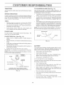
LUBRICATION
Only use high quality detergent oil rated with API service
classification S F or SG. Select the oil's SAE viscosity grade
according to your expected operating temperature.
O_L ORA_N
SAE VISCOSITY GRADES
FIG, 16
_F
"20 °
°c -3oo
0o
-20°
TEMPERATURE
30 °
-loo
RANGE
32°
40 °
60 °
o°
ANTICIPATED
lo°
BEFORE
80 °
_oo
NEXT
100 °
30°
CLEAN
40°
AiR SCREEN
(See Fig, 18)
Air screen must be kept free of dirt and chaff to prevent
engine damage from overheating. Clean with a wire brush
or compressed air to remove dirt and stubborn dried gum
fibers.
OIL CHANGE_
FIG. 15
NOTE: Although multi-viscosity oils (5W30, 10W30 etc.)
improve starting in cold weather, these multi-viscosity oils
will result in increased oil consumption when used above
32°R Check your engine oil level more frequently to avoid
possible engine damage from running low on oil.
AiR FILTER
(See Fig. 17)
Your engine will not run properly using a dirty air filter.
Clean the foam pre-cleaner after every 25 hours of opera
tion or every season. Service paper cartridge every 100
hours of operation or every season, whichever occurs firsL
Change the oi! after the first two hours of operation and
every 50 hours thereafter or at least once a year if the tractor
is not used for 50 hours in one year.
Service air cleaner more often under dusty conditions.
Checkthe crankcase oil level before starting the engine and
after each eight (8) hours of operation. Tighten oil fill cap/
dipstick securely each time you check the oil level.
Remove wing nut and cover.
•
19
Remove seal and cartridge plate.
"TO SERVICE PRE_CLEANER
ENGINE
Slide foam pre-cleaner off cartridge.
o
Wash it in liquid detergent and water.
o
Squeeze it dry in a clean cloth,
Replace the engine oil filter every season or every other oil
change if the tracter is used more than 100 hours in one
year.
o
Saturate it in engine off. Wrap it in clean, absorbent
cloth and squeeze to remove excess oil
TO SERVICE CARTRIDGE
o
OIL F_LTER
Gently tap the flat side of the paper cartridge to diso_
lodge dirt. Do not wash the paper cartridge or use
pressurized air, as this will damage the cartridge°
Replace a dirty, bent, or damaged cartridge,
o
Reinstall the pre-cleaner
paper cartridge.
(cleaned and oiled) over the
o
Reassemble air cleaner, cartridge plate, and seal
Instalt the air cleaner cover and wing nut. Tighten wing
nut 1/2 turn to 1 futl turn after nut contacts cover. Do not
overtighten.
COVER
MUFFLER
Inspect and replace corroded muffler and spark arrester (if
equipped) as it coutd create a fire hazard and/or damage.
SPARK
PLUGS
Replace spark plugs at the beginning of each mowing
season or after every 100 hours of use, whichever comes
firsL Spark plug type and gap setting is shown in "PRODUCT SPECIFICATIONS" on page 3 of this manual
IN-UNE
FUEL F_LTER
(See Fig. 19)
The fuel filter should be replaced once each season, If fuel
fiiter becomes clogged, obstructing fuel flow to carburetor,
replacement is required.
o
With engine cool, remove filter and ptug [uet line
sections.
o
Place new fuel filter in position in fuet line with arrow
pointing towards carburetor.
Be sure there are no fuel line leaks and clamps are
properly positioned.
Immediately wipe up any spilled gasoline.
CLAMP
FiG, 17
FUEL
FILTER
ENGINE
COOLING
F_NS (See Fig. 18)
Remove any dust, dirt or oil from engine cooling fins to
prevent engine damage from overheating. Engine blower
housing must be removed. Remove side panels and hood
(See "TO REMOVE HOOD AND G RILL ASSEMBL.Y"in the
Service and Adjustments section of this manual).
COOLING FiNS
(BOTH SIDES)
SCREEN
RGo 19
CLEANING
Clean engine, battery., seat, finish, etc, of all foreign
matter.
o
Keep finished surfaces and wheels free of all gasoline,
oil, etc_
o
Protect painted surfaces with automotive type wax_
We do not recommend using a garden hose to clean your
tractor unless the electrical system, muffler, air filter and
carburetor are covered to keep water out. Water in engine
can result in a shortened engine life.
\
RG. 18
E
CAUTION:
BEFORE PERFOFIMING ANY SERVICE OR ADJUSTMENTS:
®
Depress
,
,
Place motion contre_ iever in neutral (N) position.
Place attachment clutch in "DISENGAGE[}" position.
Turn ignitien key "OFF" and remove key.
Make sure the blades and aH moving parts have comp_etemy stopped,
®
,
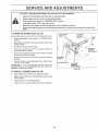
TO REMOVE
clutch/brake
Disconnect
pMug°
MOWER
pedaJ fully and set parking
brake,
spark plug wire from spark plug and place wire where it cannot come in contact with
(See Fig. 20)
SUSPENSION
ARMS
Mower will be easier to remove from the right side of tractor.
•
Place attachment dutch switch in "DISENGAGED"
position.
o Move attachment lift lever forward to lower mower to its
lowest position.
ELECTRIC
CLUTCH
PULLEY
FRONT
UNK
Roll belt off electric clutch pulley.
o
Disconnect anti-sway bar from chassis bracket by
removing retainer spring.
o
Disconnect suspension arms from rear deck brackets
by removing retainer springs.
Disconnect front links from deck by removing retainer
springs.
_ER
SPRINGS
(BOTH BIDES)
RETAINER
SPRING
Raise lift lever to raise suspension arms. Slide mower
out from under tractor.
iMPORTANT: IF AN ATTACHMENT OTHER THAN THE
MOWER DECK IS TO BE MOUNTED ON THE TRACTOR,
REMOVE THE FRONT LINKS•
TO iNSTALL
MOWER
ANT!-SWAY
Raise attachment
•
Slide mower under tractor with discharge guard to right
side of tractor.
,
Lower lift lever to its lowest position.
Install mower in reverse order of removal instructions.
RETAINER
SPRINGS
(BOTH SIDES)
FIG, 20
(See Fig. 20)
=
BAR
lift lever to its highest position.
21
D
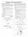
TO LEVEL
MOWER
HOUSING
FRONT°TO-BACK
Adjust the mower while tractor is parked on level ground or
driveway.
Make sure tires are properly inflated (See
"PRODUCT SPECIFICATIONS" on page 3 of this manual).
if tires are over or undednfiated, you wiJtnot properly adjust
your mower,.
SJDE.-TOoSIDE ADJUSTMENT
Raise mower to its highest position.
o
At the midpoint of both sides of mower, measure height
from bottorn edge of mower to ground. Distance"A"on
both sides of mower should be the same or within 1/4"
of each other.
Check adjustment on right side of tractor. Measure dis,_
tance"D" directly in front and behind the mandrel at bottom
edge of mower housing as shown.
Before making any necessary adjustments, check that
both front links are equal in Jength. Both links should be
approximately 10,3/8".
if adjustment is necessary, make adjustment on one
side of mower only.
o
To raise one side of mower, tighten tift !ink adjustment
nut on that side.
e
To lower one side of rnower, !oosen lift link adjustment
nut on that side.
If links are not equat in length, adjust one tink to same
tength as other link,
To lower front of mower loosen nut "E" on both front
links an equal number of turns.
NOTE: Each furl turn of adjustment nut will change mower
height about 1/8".
Recheck measurements
BOTTO_,zl EDGE
OF MOWER TO
GROUND
o
after adjusting.
r-
BOTTOM EDGE
OF MOWER TO
GROUND
q
(See Figs. 23 and 2@
To obtain the best cutting resuRs, the mower housing
should be adjusted so that the front is approximately 1/4" to
3/4" Jower than the rear when the mower is in its highest
pos)tion.
(See Figs. 21 and 22)
o
ADJUSTMENT
_4PORTANT:
DECK MUST BE LEVEL SDEZTQ-SIDE.
iF
THE FOLLOWING
FRONT,.TO-BACK
ADJUSTMENT
IS
NECESSARY,
BE SURE TO ADJUST BOTH FRONT LINKS
EQUALLY
SO MOWER
WiLL STAY LEVEL SIDE-TOSIDE.
o
\
When distance "D" is 1/4" to 3/4" lower at front than
rear, tighter_ nuts "F" against trunnion on both front
links.
To raise front of mower, loosen nut"F" from trunnion on
both front links. Tighten nut "E" on both front links an
equat number of turns.
When distance "D" is 1/4" to 3/4" lower at front than
rear, tighten nut"F" against trunnion on both front links.
Recheck side*to-side adjustment.
A T _........
W ...... 7-GROUNDUNE
FIG. 21
FIG. 23
SUSPENSION
ARM
LIFT UNK
ADJUST&']ENT
NU_[
F_Go22
NUT"E"
NUT "F ...........
-%
FRONT URKS
22
TRUNNION
FIG. 24
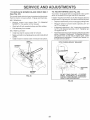
TO REPLACE
(See Fig, 25)
MOWER
BLADE
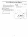
TO ADJUST
DRIVE BELT
The mower b!ade drive belt may be replaced without tools.
Park the tractor on level surface. Engage parking brake.
Remove mower from tractor (See "TO REMOVE
MOWER" in this section of this manual).
Work bett off both mandrel pulleys and idler pulleys.
o
o
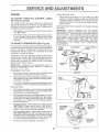
Depress clutch/brake pedal and engage parking brake.
o
Measure distance between brake operating arm and
nut "A" on brake rod.
If distance is other than 1-3/4", loosen jam nut and turn
nut "A" unti! distance becomes 1-3/4". Retighten jam
nut against nut "A".
Puff belt away from mower.
BELT INSTALLATION
(See Fig. 26)
If tractor requires more than six (6) feet stopping distance
at high speed in highest gear, then brake must be adjusted
BELT REMOVAL
o
BRAKE
Your tractor is equipped with an adjustable brake system
which is mounted on the right side of the transaxle.
o
Install new belt in reverse order of removal.
Road test tractor for proper stopping distance as stated
above. Readjust if necessary, tf stopping distance is
still greater than six (6) feet in highest gear, furthe_
maintenance is necessary. Contact your nearest au _
thorized service center.
Make sure belt is in nit pulley grooves and inside all belt
guides.
Install mower in reverse order of removal instructions.
IDLER
PULLEYS
WITH PARKING BRAKE "ENGAGED"
MANDREL
PULLEY
JAM
NUT
\
MANDREL
PULLEY
DO NOT TOUCH THIS NUT.
IF FURTHER
BRAKE
ADJUSTMENT
IS NECESSARY,
CONTACT
YOUR NEAREST
AUTHORIZED
SERWCE CENTER/DEPARTMENT
FIG. 25
FiG. 26
23
A
TO REPLACE
_See Fig. 27}
MOTION
DR_VE
E
BELT
TO ADJUST MOTION
(See Fig. 28}
Park the tractor on level surface. Engage parking brake.
For assistance, there is a belt installation guide decal on
bottom side of left footrest.
o
o
Remove mower (See "TO REMOVE MOWER" in this
section of this manual.)
Disconnect clutch wire harness.
o
Remove clutch Iocator.
o
Remove upper belt keeper.
o
Remove belt from stationary idler and clutching idler.
o
Pull belt slack toward rear of tractor. Carefully remove
be!t upwards from transmission input pulley and over
cooling fan blades_
CONTROL
LEVER
]he motion control lever has been preset at the factory and
adjustment should not be necessary.
If for any reason the motion control lever wiil not hold its
position whi!e at a selected speed, it may be adjusted at the
friction pack Iocated on the right side of transmission.
Park tractor on level surface. Stop tractor by turning
ignition key to "OFF" position, and engage parking
brake.
o
Adjust motion control lever by tightening adjustment
tocknut one half (1/2) turn.
NOTE: if for any reason the effort to move the motion
control lever becomes too excessive, reverse the above
adjustment procedure by !oosening locknut t/4 to 1/2 turn.
Pull belt toward front of tractor and remove downwards
from around electric clutch.
Road test tractor after adjustment and repeat procedure it
necessary.
o Install new bett by reversing above procedure.
_t,
J1POF_TANT: MAKE SURE UPPER BELT KEEPER IS
POSITIONED PROPERLY BETWEEN LOCATOR TABS
AND ELECTR!C CLUTCH WIRE CONNECTION
IS
SECURE_
CLUTCH LOCATOR
TABS
IDLER
STATIONAR
IDLER
\
ADJUSTMENT
LOCKNUT
TRANSMI_
IHPUTPULLEY
CLUTCH
WiRE
HARNESS
FIGo 28
TRANSB_ISS_ON
REMOVAL/REPLACEMENT
Should your transmission require
replacement, it should be purged
before operating the tractor See
SION" in Operation section of this
FIG. 27
24,
remova! for service or
after reinstaltation and
"PURGE TRANSM!S _,
manual.
SERVICE AN
TO ADJUST
STEERING
WHEEL
ALIGNMENT
TO START ENGINE WiTH A WEAK
'See Fig, 30}
If steering wheel crossbars are not horizontal 0eft to right)
when wheels are positioned straight forward, remove steering wheel and reassemble per instructions in the Assembly
section of this manual.
FRONT WHEEL
CAUTION:
i_
TOE-IN/CAMBER
The front wheel toe-in and camber are not adjustable on
your tractor, tf damage has occurred to affect the front
wheel toe--in or camber, contact your nearest authorized
service center/department.
TO REMOVE WHEEL
(See Fig. 29)
,
Repair tire and reassemble.
•
On rear wheels only: align grooves in rear wheel hub
and axle. Insert square key.
,
Replace washers and snap retaining ring securely in
axle groove.
o
Replace axle cover.
I
and smoking materiaJs away from batatee×p_osivegases.
Keepsparka, flame
reties.
A_waya wear eye protection
when around batteries.
t
i!
IMPORTANT:
YOUR TRACTOR JS EQUIPPED WITH A 12
VOLT NEGATIVE
GROUNDED
SYSTEM.
THE OTHER
VEHICLE
MUST ALSO
BE A 12 VOLT
NEGATIVE
GROUNDED
SYSTEM.
DO NOT USE YOUR TRACTOR
BATTERY TO START OTHER VEHICLES,
Block up axle securely.
Remove axle cover, retaining ring and washers to allow
wheel removal (rear wheel contains a square key - Do
not lose).
Lead-acid batteries genero
If your battery is too weak to start the engine, it should be
recharged.
If "jumper cables" are used for emergency
starting, follow this procedure:
FOR REPAIRS
,
BATTERY
TO ATTACH JUMPER CABLES Connect each end of the RED cable to the POSITIVE
(+) terminal of each battery, taking care not to short
against chassis.
Connect one end of the BLACK cable to the NEGA_
T_VE (-) terminal of fully charged battery.
Connect the other end of the BLACK cable to gooc
CHASSIS GROUND, away from fuel tank and battery
TO REMOVE CABLES, REVERSE ORDER BLACK cable first from chassis and then from the fully
charged battery.
RED cable last from both batteries.
WASHERS
RETAINING
RING
Q
AXLE COVER
"POSmVE"
(+)
"NEGATIVE"(-)
I
SQUARE KEY
(REAR WHEEL ONLY)
FIG. 29
@
L,H, PANEL
BOLT
/
F_Go30
25
ENTS
TO REPLACE
HEADUGHT
BULB
TO REMOVE HOOD AND GRmLL ASSEMBLY
(See Fig. 31)
®
Raise hood.
o
Put! bulb holder out of the hole in the backside of the
grill.
-
Replace bulb in holder and push bulb holder securely
back into the hole in the backside of the grill.
Close hood.
,
Stand in front of tractor. G rasp hood at sides, tilt toward
engine and lift off of tracton
•
To replace, reverse above procedures.
INTERLOCKS
Raise hood.
Unsnap headlight wire connector.
AND RELAYS
Loose or damaged wiring may cause your tractor to run
poorly, stop running, or prevent it from starting.
Check wiring. See electrical wiring diagram in the
Repair Parts section of this manual.
TO REPLACE
FUSE
Replace with 30 amp automotive-type plug-in fuse. The
fuse holder is located behind the dash.
HEADLIGHT
WiRE
CONNECTOR
HOOD
FIG. 31
26
E
DJ
ENGINE
TO
ADJUST
ACCELERATION
THROTTLE
CONTROL
o
CABLE
(See Fig° 32 and 33)
The thlottle control has been preset at the factory and
adjustment should not be necessary. Check adjustment as
described below before loosening cable. If adjustment is
necessary, proceed as follows:
,
(See
Fig. 34)
The carburetor has been present at the factory and adjustment should not be necessary. However, minor adjustment
may be required to compensate for differences in fuel,
temperature, altitude or load. If the carburetor does need
adjustment, proceed as follows:
Move throttle control lever from slow
position. If engine hesitates or dies,
screw out (counterclockwise)
1/8 turn.
continue to adjust, if necessary,
until
ates smoothly.
CASING
CLAMP
SCREW
adjusted.
(_)
to fast (@)
turn idle mixture
Repeat test and
engine acceter
Do not adjust-damage
STOP SCREW
SPEED CONTROL
LEVER
C,
In general, turning the adjusting needles in (clockwise)
decreases the supply of fuel to the engine giving a leaner
fuel/air mixture. Turning the adjusting needles out (coum
terclockwise) increases the supply of fuel to the engine
giving a richer fuel/air mixture.
Bt_PORTANT: DAMAGE TO THE NEEDLES AND THE
SEATS IN CARBURETOR MAY RESULT IF SCREW IS
TURNED IN TOO TIGHT.
PRELIMINARY
-
_MPORTANT:
NEVER TAMPER
WITH THE ENGINE
GOVERNOR,
WHICH IS FACTORY
SET FOR PROPEFI
ENGINE SPEED. OVERSPEEDING
THE ENGINE ABOVE
THE
FACTORY
HIGH
SPEED
SETTING
CAN
BE
DANGEROUS.
IF YOU THINK THE ENGINE-GOVERNED
HIGH SPEED NEEDS ADJUSTING,
CONTACT
YOUR
NEAREST
AUTHORIZED
SERVICE
CENTER/
DEPARTMENT,
WHICH HAS PROPER EQUIPMENT
AND
EXPERIENCE
TO
MAKE
ANY
NECESSARY
ADJUSTMENTS.
Check that speed control lever is against stop screw. If
it is not, loosen casing clamp screw and pull threttle
cable until lever is against screw. Tighten clamp screw
securely.
CARBURETOR
TEST
High speed stop is factory
may result.
With engine not running, move throttle control lever to
fast (4/_) position.
TO ADJUST
E
THROTTLE
CABLE
SETTING -
o
Be sure you have a clean air filter, and the throttle
control cable is adjusted properly (see above).
,
With engine off turn idle fuel adjusting needle in (clockwise) closing it finger tight and then turn out (counterclockwise) 1-1/4 turns.
FIG. 32
STOP
SCREW
Turn main fuel adjusting needle in (clockwise) closing
finger tight and then turn out (counterclockwise) 1 turn.
SPEED
CONTROL
LEVER
FINAL SETTING o
Start engine and allow to warm for five minutes. Make
final adjustments with engine running and shift/motion
control lever in neutral (N) position.
o
With throttle control lever in fast (@) position, turn main
fuel adjusting needle in (clockwise) until engine begins
to die then turn out (counterclockwise) until engine
runs rough. Turn needle to a point midway between
those two positions.
RG. 33
Idle sj:)eed setting o With throttle control lever in slow
(-_) position, engine should idle at 1400 RPM. if
engine idles too slow or fast, turn idle speed adjusting
screw in or out until correct idle is attained.
o
Idle fuel needle setting - With throttle control lever in
slow (._) position, turn idle fuel adjusting needle in
(clockwise) until engine begins to die and then turn out
(counterclockwise) until engine runs rough. Turn needle
to a point midway between those two positions.
o
Recheck idle speed. Readjust if necessary.
FUEL
ADJUSTING
NEEDLE
ADJUSTING
SCREW
FUEL
ADJUSTING
NEEDLE
27
F_G. 34
E
Immediately
prepareyourtractorforstorageattheendof
'heseasonor ifthetractorWillnotbeusedfor30daysor
more.
CAUTION:Neveretorethe traetorwith
gasoline in the tank insidea building
wherefumesmayreachanopenflame
or spark° A_lowthe engineto coo_
beforestoring in arryenclosureo
TRACTOR
Remove mower from tractor for winter storage. When
mower is to be stored for a period of time, clean it thor-.
ougNy, remove all di_, grease, leaves, etc. Store in a
clean, dry area.
Clean entire tractor (See "CLEANING" in the Customer
Responsibilities section of this manuai)°
Inspect and replace belts, if necessary (See belt re_
placement instructions in the Service and Adjustments
section of this manual).
o
Lubricale as shown in the Customer Responsibilities
section of this manual.
Be sure that all nuts, bolts and screws are securely
fastened. Inspect moving parts fordamage, breakage
and wear. Replace if necessary..
o
Touch up all rusted or chipped paint surfaces; sand
lightty before painting.
BATTERY
ENGMNE
FUEL SYSTEM
_aPORTANT:
IT IS IMPORTANT
TO PREVENT
GUM
DEPOSITS
FROM FORMING
tN ESSENTIAL
FUEL
SYSTEM PARTS SUCH AS CARBURETOR,
FUEL. FILTER
FUEL HOSE, OR TANK DURING
STORAGE
ALSO,
EXPERW!NCE
INDICATES
THAT ALCOHOL
BLENDED
FUELS (CALLED
GASOHOL
OR USING ETHANOL
OR
METHANOL) CAN ATTRACT MOISTURE WHICH LEADS
TO SEPARATION
AND FORMATION
OF ACIDS DURING
STORAGE.
ACIDIC
GAS CAN DAMAGE
THE FUEL
SYSTEM OF AN ENGINE WHILE IN STORAGE.
o
Drain the fuel tank_
o
Start the engine and let it run until the fuef lines and
carburetor are empty.
o,
Never use engine or carburetor cleaner products in the
fuel tank or permanent damage rnay occur.
Use fresh fuel next season.
NOTE:
Fuel stabilizer is an acceptable alternative in
minimizing the formation of fuet gum deposits during stor*
age. Add stabilizer to gasoline in _uel tank or storage
container. Always fotiow the mix ratio found on stabilizer
container. Run engine at least 10 minutes after adding
stabilizer to allow the stabilizer to reach the carburetor. Do
not drain the gas tank and carburetor if using fuel stabilizer.
ENGmNE OML
Drain oil (with engine warm) and replace with clean engine
eii. (See "ENGINE" in the Customer Responsibilities
section of this manual).
o
Fully charge the battery for storage.
o
After a period of time in storage, batten/may
recharging.
•
To help prevent corrosion and power leakage during
long periods of storage, battery cables should be
disconnected and battery" cleaned thoroughly (see "TO
CLEAN BATTERY AND TERMINALS" in the Customer Responsibilities section of this manual).
Pour one ounce of oil through spark plug hole(s) into
cylinder(s).
o
After cleaning, leave cables disconnected and place
cables where they cannot come in contact with batlery
terrnina]s.
Replace with new spark plug(s).
OTHER
o
Be sure battery drain tube is securely atI:ached.
o
Do not store gasoline from one season to another.
If battery is removed from tractor for storage, do not
store battery directly on concrete or damp surfaces.
o
Replace your gasoline can if your can starts 1o rust
Rust and/or dirt in your gasoline will cause problems
o
Jf possible, store your tractor indoors and cover it to
give protection from dust and dirt.
require
CYLINDERS
Remove spark plug(s).
Turn ignition key to "START" position for a few seconds
to distribute oil.
Cover your tractor' with a suitable protective cover that
does not retain moisture. Do not use plastic. Plastic
cannot breathe which allows condensalion to form and
will cause your tractor to rust.
IMPORTANT: NEVER COVER TRACTORWHiLEENGINE
AND EXHAUST AREAS ARE STILL WARM.
POINTS
PROBLEM
Will not start
CAUSE
CORRECTION
1.
Out of fuel.
2.
3.
4.
5.
6.
7.
Engine riot"CHOKED"
Engine flooded.
Bad spark plug=
Dirty air filter.
Dirty fuel filter.
Water in fuel.
!.
Fill fueltank.
properly.
2.
3.
4.
5.
6_
7.
8.
9.
10.
Loose or damaged wiring.
Carburetor out of adjustment.
Engine valves out of adjustment.
8.
9.
10.
See "!"O START ENGINE" in Operation section
Wait several minutes before attemptir_g to start.
Replace spark plug.
Clean/replace air filter.
Replace fuel filter.
Drain fuel tank and carburetor, refill tank with fresh
gasoline and replace fuel filter.
Check all wiring.
Contact an authorized service center/department.
Contact an authorized service center/department.
1.
2.
3.
4.
5.
6.
7.
8.
Dirty air filter.
Bad spark plug.
Weak or dead battery.
Dirty fuel filter.
Stale or dirty fue!.
Loose or damaged wiring.
Carburetor out of adjustment.
Engine valves out of adjustment.
1.
2.
3.
4.
Clean/replace air filter.
Replace spark plug.
Recharge or replace battery.
Replace fuel filter.
5.
6.
7.
8.
Drain fuel tank and refil! with fresh gasoline.
Check all wiring.
Contact an authorized service centerideparlment.
Contact an authorized service center/department.
I.
2.
3.
4.
Clutch/brake pedal not depressed.
Attachment clutch is engaged.
Weak or dead battery.
Blown fuse.
5.
6.
7.
8.
9.
Corroded battery terminals
Loose or damaged wiring.
Faulty ignition switch.
Faulty solenoid or starter.
Faulty operator presence switch(es).
1.
2.
3.
4.
5.
6.
7.
8.
9.
Depress clutch/brake pedal.
Disengage attachment clutch.
Recharge or replace battery.
Replace fuse.
Clean battery terminals.
Check all wiring.
ChecWreplace ignition switch.
Chectdreplace solenoid or starter.
Contact an authorized service center/department.
Engine clicks but will not
start
1.
2.
3.
4.
Weak or dead battery.
Corroded battery terminals.
Loose or damaged wiring.
Faulty solenoid or starter.
1.
2.
3.
4.
Recharge or replace battery.
Clean battery terminals.
Check all wiring
Check/replace solenoid or starter.
Loss of power
1.
2.
3.
4.
5.
6.
7.
8.
9.
Cutting too much grass/too fast.
Throttle in "CHQKE"position.
Build-up of grass, leaves and trash under mower.
Dirty air filter.
Low oil level/dirty oil.
Faulty spark plug.
Dirty fuel filter.
Stale or dirty fueI.
Water in fuel.
I.
2.
3.
4.
5.
6.
7.
8.
9.
Set in "Higher Cut" position/reduce speed.
Adjust throttle control.
Clean underside of mower housing.
Clean/replace air filter.
Check oil level!change oi!.
Clean and regap or change spark plug.
Replace fuel filter.
Drain fuel tank and refill with fresh gasoline.
Drain fuel tank and carburetor, refill tank with fresh
gasoline and replace fuel filter.
Connect and tighten spark plug wire.
Clean engine air screen/fins.
Clean/replace muffler.
Check all wiring.
Contact an authorized service center!department.
Contact an authorized service center!department.
Hard to start
Eng}ne will not turn over
10.
11.
12.
13.
14.
!5.
Excessive
vibration
Spark plug wire loose.
Dirty engine air screen/fins.
Dirty/clogged muffler.
Loose or damaged wiring,
Carburetor out of adjustment.
Engine valves out of adjustment.
I.
2.
Worn, bent or loose blade.
Bent blade mandrel.
3.
Loose/damaged
10.
11.
12.
13.
14.
!5.
1.
2.
3.
part(s).
29
Replace blade. Tighten blade bolt.
Replace blade mandrel.
Tighten loose part(s). Replace damaged parts.
PROBLE_
CAUSE
Engine continues to run
when operator leaves seat
with attachment c!utch
engaged
I.
Faulty' operator-safety
Poor cut o-uneven
t,
2.
CORRECTION
presence control system.
1.
Check wiring, switches and connections.
If not
corrected, contact an authorized service center/
department,
Worn, bent or loose blade.
Mower deck not level.
i.
2.
Reptace blade Tighten blade bolt,
Level mower deck.
3.
4.
Buildup of grass, leaves, and bash under mower.
Sent blade mandrel.
5.
Clogged mower deck vent holes bom buildup of
grass, leaves, and trash aroend mandrels.
3.
4.
5
Clean underside ot mower housing.
Rep}ace blade mandrel
Clean around mandrels to open vent holes.
Mower biades wil_ not
rotate
I.
2,
3.
4.
Obstruction in clutch mechanism.
Worn/damaged mower drive belt.
Frozen idler pulley.
Frozen blade mandrel,
1.
Remove obstruction.
2.
3.
4.
Replace mower drive belt.
Replace idler pulley.
Replace blade mandrel
Poor grass discharge
'1.
2.
3.
4,
Engine speed too slow.
Travel speed too fast.
Wet grass,
Mower deck not level
1.
2,
3.
4.
Place throttle control in "FAST" position.
Shift to slower speed.
Allow grass to dry before mowing,
Level mower deck.
5.
6.
7.
8.
Low/unevea tire air pressure.
Worn, bent or loose blade.
Buildup of grass, leaves and trash under mower.
Mower ddve belt worn.
9.
!0.
11.
Blades improperly installed.
Improper blades used.
Clogged mower deck vent holes from buildup of
grass, leaves, and trash around mandrels.
5.
6.
7,
8.
9,
10.
1.
Check tires for proper air pressure,
Replace/sharpen blade. Tighten blade bolt.
Clean underside of mower housing.
Replace mower drive belt.
Reinsta!l blades sharp edge down.
Replace with blades listed in this manual.
Clean around mandrels to open vent holes.
1,
Switch is "OFF".
1.
Turn switch "ON".
2.
3.
4.
5
Bulb(s) burned out,
Faulty light switch.
Loose or damaged wiring.
Blown Iuse,
2,
3_
4
5.
Replace bulb(s),
ChecWreptace light switch,
Check wiring and connections=
Replace fuse.
1.
2.
Bad battery cetl(s).
Poor cable connections.
1.
2,
Replace battery.
ChecWclean at! connections.
3,
4.
Faulty regulator (if so equipped),
Fauky alternator.
3.
4.
Replace regulator.
Replace akernator_
Tractor "creeps'* with
motio[_ control lever in
"neutraF' positio_
(Fender shift mode{s onIy)
1.
Motion control ]ever is out of adiustment.
1.
Adjust motion controI lever.
Loss of drive
I,
2.
3.
Freewheel contro! in "disengaged" position.
Motion drive belt worn, damaged, or broken.
Air trapped in transmission during shipment
or servicing.
1,
2.
3.
Place freewheel control in "engaged" position.
Replace motion drive belt.
Purge transmission.
Headlight(s) not working
(if so equipped)
Battery
will not ci_arge
Engine "backfires"
when turning eHg_ne
OFF'*
Engine throttle contro not set at "SLOW"
position for 30 seconds before s opp _l9 eofi ne
Move throttle control to "SLOW" pesition and allow
to idle for 30 seconds befere s_oppiag anr._ine
TRACTOR
_ o MODEL
NUMBER
917,2527!1
RED
BLACK
BATTERY
I
RED
AMMETER
BLACK
IGNITION
SWITCH
BLACK
(R EGULATOR
I ........
DISCONNECTED)
I
ORANGE
ff
:-:L::---..
HEADLiGBT
SWITCH (OFF)
t_S .........
J
,
HEADLIGHTS
'%. !,_:/_
"- L':'::L:I:;::':jJ
IGNITION SWITCH
4ON
START
@
G FC
NON-REMOVABLE
CONNECTIONS
WIRING INSULATED
REMOVABLE
CONNECTIONS
CLIPS
NOTE: IF WIRING INSULATED
CLIPS WERE REMOVED FOR
SERVICING OF UNiT THEY
SHOULD BE REPLACED ]O
PROPERLY SECURE YOUR WIRING
3t
II I1_
E _!f B
o
_A
PTO SWITCH
REPAIR PARTS
TRACTOR
°oMODEL
NUMBER
917.252711
ELECTRICAL
4O
42
26
34
I-_
45
U
/
/
,'
25
/
4
9
6
'12
29
55
7
J
28
32
REPAIR PARTS
TRACTOR
o o MODEL NUMBER
917=252711
ELECTRICAL
KEY
NO.
1
2
3
4
6
7
8
9
•10
1!
t2
19
20
2t
22
24
25
26
28
29
30
3!
32
33
34
35
36
39
40
4t
42
43
44
45
49
50
51
55
70
PART
NOo
DESCR_PTION
144926
74760412
STD551025
STD551125
STD54t025
7697J
7603J
!09596X
145211
145209
145769
STD551125
73350400
136850
4152J
146148
4799J
108824X
145491
121305X
144921
140400
141226
1404.03
110712X
108236X
STD601005
109553X
149170
71110412
131563
145673
73800400
122822X
11151000
146283
140405
17490508
140427
Battery
Bolt, Hex 1/4-20 UNC x 3/4
Washer
Washer
Nut
Tube, Plastic
Tray, Battery
Clamp, Hose
Bolt
Holddown Battery Dash Mount
Nut, Push Nylon i/4
Washer, Lock
Nut, Hex, Jam 1/4-20 UNC
Harness, Light Socket W/4152J
Bulb, Light
Cable, Battery
Cable Battery
Fuse
Cable, Ground
Switch, Hunger
Switch, ignition
Nut, Ignition
Cover, ignition Switch
Key, Ignition
Switch, Light
Bracket, Switch
Screw
Switch, tnter!ock
Harness, _gnition
BoltBIkFinHex
I/4-20UNCx3!4
Cover', Terminal
Solenoid
Nut, Lock W/Insert 1/4o20 UNC
Ammeter Rectangular 15 Amp.
Washer Lock Internal Tooth 5/8
Switch PTO 3 PDT Red Delta
Ring Retainer PTO
Screw Thdrol 5/!6.q8 x 1/2 TYT
Harness Engine
NOTE: All component dimensions given in U_S=inches
1 inch = 25.4 rnm
33
REPAIR PARTS
TRACTOR
CHASSIS
o o MODEL NUMBER
917.252711
AND ENCLOSURES
30
119
87
29
J i
_
"
25
i
26
25
47
28
26
121
44
IO0
71
68
9
124
115
3
117
123
73
°_
86
114
117
3
33
10
34
34
REPAmR PARTS
TRACTOR
CHASSIS
KEY
NOo
° o MODEL NUMBER
917.2527!1
AND ENCLOSURES
PART
NO.
1
2
3
14550t
140356
17490612
6
7
8
9
10
11
13
14
145206
145351
126471X
145203
72140608
14.52!8
145217
17490608
17
24
25
26
28
29
30
31
33
34
35
36
38
39
136673X558
STD523710
19131312
STD541437
136373X428
136374
140002X558
137113
145244X558
I45243X558
STD533707
!08067X
139886
139887
DESCRIPTION
Chassis
Drawbar
Screw, Thd., Roll. 3/8-16 x 3/4
Type TT
Saddle
Heat Shield
Clip Insulator
Dash, Plastic
Bolt, Carriage 3/8-16 x 1
Panel, Dash, LH
Panel, Dash, RH
Screw, Thd., Roll. 3/8o16 x 1/2
Type TT
Hood Assembly
Bolt
Washer 13/32 x 13/16 x 12 Gauge
Nut
Grill
Lens, Bar, Clear
Fender
Bracket Assembly, Fender
Footrest, LH
Footrest, RH
Bolt
Nut, Pal
Bracket Assembly, Pivot, LH
Bracket Assembly, Pivot, RH
KEY
NO.
PART
NO.
44
47
50
59
64
66
69
7t
73
75
86
87
90
100
t14
t15
119
t20
121
122
123
140675
10553tX
137304
110436X
145095
143485X014
140181
73640400
17580408
108067X
136670X558
136671X558
STD551025
t05037X
145349
121794X
19092016
137270
137269
137271
136814
124
136813
125 74180412
NOTE:
35
DESCRIPTION
Fender Strap
Nut, Push, Nylon
Rod, Support Hood
Bushing, Snap, Split
Dash, Lower
Plate, Dash
Plate, Support, Battery
Nut
Screw Tap Lite 1/4-20 x 1/2
Nut, Pal
Panel Assembly, RH
Panel Assembly, LH
Washer 17/64
Strip Foam
Bracket, Support, Dash
Cover Access Black Square
Washer 9/32 x 1-I/4 x 16 Ga.
Rivet, Rachet, Male
Washer, Nylon
Rivet, Ratchet, Female
Bracket Assembly, Front Pivot
Hinge, LH
Bracket Assembly, Front Pivot
Hinge, RH
Screw, Machine 1/4-20 x 3/4
All component dimensions given in U.So inches
1 inch = 25.4 mm
TRACTOR--
MODEL
NUIV_BER 9!7.252711
57
61
56
41
45
35
32
61
3_(_
44
103
52
8
97
•48
62
53
'
"
I T
98
30
61
91
16
84100
104
27
77
9
24
22
55
105
78
36
100
REPAIR PARTS
TRACTOR
o MODEL
NU IBER 917o25271t
DRIVE
KEY
NO.
1
2
3
8
9
10
15
16
I7
18
!9
20
21
22
23
25
26
27
28
29
30
31
32
33
34
35
36
37
38
39
40
4i
42
43
44
45
46
47
48
49
50
51
52
53
55
PART
NOo
144436
142431
143995
14.1002
13714O
76020416
74780544
73800500
126197X
74780616
73800600
71170768
130564
145240
137141
106888X
19131316
76020412
145204
124236X
130807
127275X
74760512
STD533107
122424X
120183X
19211616
1572H
123674X
74760644
4470J
109070X
19131312
19111012
I05706X
!10812X
12000039
127783
t23789X
123205X
74760624
STD 541437
73680500
105710X
105709X
KEY
NO.
DESCRIPTION
56
57
58
59
60
61
62
63
65
67
68
69
71
72
73
74
75
76
77
78
81
82
83
84
86
87
88
89
91
92
93
94
95
96
97
98
100
102
103
104
!05
106
Transaxle Assembly
Spring, Return, Brake
Pulley, Transaxle
Rod Shift Hydro LT
ChJtch Elect
Pin Cotter 1/8 x 1 CAD
Bolt Fin Hex 5/t6-18 Unc
Nut Lock Hex W/Ins. 5/16o18 Uric
Washer lq/20D
x I5/32 ID x .250
Bolt Fin Hex 3/8.-16 Unc x ! Gr. 5
Nut Lock Hex W[Wsh 3/8-.16 Unc
Bott Hex 7/16-20 x 4.-1/4 Ga. 5
Knob, Deluxe 1/2q3
Rod, Brake Hydro
Bracket Asm. Mtg CL
Spring, Brake Rod
Washer
Pin Cotter 1/8 x 3/'4 CAD.
Rod, Parking Brake
Cap, Parking Brake
Bracket, Transaxle
Keeper Belt Lh
Bolt Hex Hd 5/16.-t8 Unc x 3/4
Bolt RDHD SQNK 5/16-18 x 3/4
Shaft, Foot Pedal
Bearing, Nylon
Washer
Pin, Roll
Pulley, Idler, Fiat
Bolt
Spacer, Split
Keeper, Belt Retainer
Washer 13/32 x 13/16 x 12 Gauge
Washer 11/32 x 5/8 x 12 Ga.
Bearing, Nylon
Washer, Hardened
Ring, Klip
Putley, Idler, V-Groove
Bellcrank Assembly
Retainer, Belt
Bolt
Nut, Crownlock 3/816
Nut, Crowniock 5/16-18 Unc
Link, Clutch
Spring, Return, Clutch
PART
NO.
74760620
140294
140470
140312
1212!8X
17490612
8883R
140186
STD551t43
STD523710
105730X
142432
140158
19132012
140157
121199X
121749X
12000001
123583X
121748X
140154
t23782X
19171216
140548
71208
19212016
12000008
'139989
74780536
74780524
142564
140462
14464.3
4497H
140469
73510600
19111216
141322
50831
140156
71070516
74780520
NOTE:
37
DESCRiPTiON
Bolt 14ex 3/8-.16 x lq/4
V-.Bett, Ground Drive
Keeper Bolt Lh Hydro 0750. t8/20"
Keeper, Center Span
Keeper Belt Engine
Screw ThdroL 3/8q6 x 3/'4 Ty_ TT
Cover, Pedal
Pulley, Engine
Washer Lock Hvy HLCL Spr. 7/16
Bolt Fin Flex 3/8o16 x 1
Keeper Belt Engine
Screw
Strap Torque Lh Hydro 18/20" T
Washer 13/32 x 1_1/4 x !2 Gauge
Strap Torque Rh Hydro 18/20" T
Spacer, Split
Washer 25/32 x !ol/4 x 16 Gauge
E-Ring
Key, Square
Washer 25/32 x !-5/8 x !6 Gauge
Shaft Asm. Cross Hydro 20" Tires
Spring Torsion T/A
Washer 17/32 x 3/4 x 16 Ga.
Rod, Tie Hydro 20" Tires
Bushing Rod Strig. 629/632 [D
Washer 21/32 x 1_!/4 x 16 Ga_
Ring Klip #5304-82
Console, Shift
Bolt Fin Hex 5/!6-18 x 2-1/4
Bolt Fin Hex 5/6-18 Unc x 1-1/2
Line Fuel Hydro 4"
Fan, Hydro 7"
Control Bypass Hydro 20" Tires
Retainer Spring 1" Zinc/Cad
Keeper Bolt Rh Hydro 0750.18/20"
Nut Keps Hex 3/8o16 Unc
Washer 11/32 x 3/4 x t6 Ga.
Washer Beltville .501D x 1.50D
Nut Nylon Insert !/2-20 Urff.
Arm, Control Hydro
Screw Cap Hex 5/16 x t8 x t
Bolt Fin Hex 5/16q8 Unc x 1-1/4
All componen[ dimensions
! inch = 25.4 mm.
give in US. inches.
REPAIR PARTS
TRACTOR
STEERING
° _ MODEL
NUMBER
9!7o252711
ASSEMBLY
"_.
r-___
42
62
47
14
._.,..f17
32
11
12
33
j_
10
34
35
J
38
REPAIR PARTS
TRACTOR
STEERING
o o MODEL NUMBER
917.252711
ASSEMBLY
KEY
NO,
PART
NO.
1
2
3
4
5
6
7
8
9
10
!1
12
!3
14
15
121472X
142033
135227
135228
6266H
12t748X
19272016
12000029
3366R
130468
STD551137
73610600
110438X
74011056
73901000
16
17
t8
19
20
21
22
132624
128758
57079
124035X
126684X
STD55!125
71070410
23
24
25
27
28
29
127501
109816X
124036X
136874
19131416
17490612
32
33
34
35
37
36
38
39
40
41
42
43
45
46
47
62
130467
STD551031
STD551137
73810500
t7541008
145207
126805X
100712K
STD541350
1007!1L
140216
121749X
t06933X
121232X
6855M
149682
DESCRIPTION
Steering Wheel
Axle Assembly, Front
Spindle Assembly, LH
Spindle Assembly, RH
Bearing, Race, Thrust, Hardened
Washer 25/32 x to5/8 x 16 Gauge
Washer 27/32 x 1-!/4 x 16 Gauge
Ring, Klip
Bearing
Link, Drag
Washer, Lock
Nut, Hex, Fin. 3/8-24 UNF
Spacer, Bearing, Front Axle
Bolt, Hex 5/8-11 UNC x 3-1/2
Loocknut, Hex, Jam, wlWasher
Insert 5/8-11 UNC
Pin, Axle, Large 5/8 x 1.55/1.54
Shaft Assembly, Steering
Washer, Thrust .5t5 x .750 x .033
Support, Shaft
Washer, Shim t/4 x 5/8 x .062
Washer
Screw, Hex Socket Read
1/4-20 x 5/8
Shaft Assembly, Pittman
Nyliner, Snap-In
Bracket, Steering
Gear, Sector
Washer 13/32 x 7/8 x 16 Gauge
Screw, Thd., Roll
3/8-16 x 3/4 Type _
Tie Rod
Washer 11/32 x 3/4 x t6 Ga.
Washer Lock Hvy HLCL Spr. 5/16
Locknut 5/16..24 UNF
Screw SLFTP #10-24 x 1/2 TT.-B
Bushing, Steering
Insert, Cap, Steering Wheel
Washer .53 x 2.25 x _160
Nut
Adapter, Steering Wheel
Boot Shaft Steering
Washer 25/32 x I-t/4 x 16 Gauge
Knob, Round
Cap, Spindle
Fitting, Grease131672
Kit, Steering Assembly
NOTE: All component dimensions given in U.S. inches
1 inch = 25.4 mm
39
\
\
9
REPAIR PARTS
TRACTOR
° o MODEL NUMBER
917.252711
ENGINE
KEY
NOo
PART
NO.
1
2
132755
177204t0
3
141948
4
5
6
7
8
9
!0
11
12
13
!37978
136215
136216
2751R
122439X
17190408
I4.5552
STD551131
74570512
..........
14
I5
16
1'7
23
24
25
26
29
31
32
33
34
35
36
37
38
13280336
13200300
11050600
17490624
128953
STD60!005
138672
STD551237
137180
141069
123549X
123487X
106082X
17490512
19132012
8543R
.......
39
40
41
81
109227X
3645J
139277
735104.00
DESCR_PTION
Control, Throttle
Screw, Hex Head, Thread Cutting
1/4-20 x 5/8
Engine, Kohter, Model No. MV18S,
Type No. PS58560
Muffler, Exhaust
Tube Manifold LH Kohler MV18
Tube Manifold RH Koh!er MV18
Clip Line Fuel
Bracket Muffler Mounting
Screw Hex WHS Thdcut 1/4-.20 UNC
Shield Heat
Washer Lock Hvy. Hlcl. Spr. 5/18
Screw Hex SKT 5/16 UNC x 3/4
Gasket (Order From Engine
Manufacturer)
Nipple, Pipe
Elbow, Standard 90 °, 3/8-18 NPT
Washer Lock Ext Tooth 3/8
Screw Thdrof 3/8-!6 x I_12 TT
Shield, Heat
Screw
Control Choke
Nut Fin Hex 3/8-24. UNF
Arrester, Spark
Tank, Fuel
Cap Assembly, Fuel
Clamp, Hose
Spacer, Pad
Screw Thdro! 5/16-18 x 3/4. TYT
Washer !3/32 x 1-1/4 x !2 Ga.
Line, Fuel
Plug, Oil Drain
(Order From Engine Manufacturer)
Spacer Pad
Bushing
Stem, Fuel Tank
Nut Keps Hex 1/4_20 UNC
NOTE: AII component dimensions gwen in U.S. inches
! inch = 25.4 mm
41
REPAR
PARTS
TRACTOR
SEAT
o o MODEL NUMBER
917o2527!1
ASSEMBLY
\
\
\
10
5
21
17
KEY
NO.
1
2
5
7
8
9
!0
11
12
13
14
15
PART
NO.
140123
140551
145006
124181X
17490508
19131614
140552
120068X"
121246X
121248X
72050411
134300
12
KEY
NOo
DESCRIPTION
Seat
Bracket, Pivot, Seat
Clip Pushqn, Hinged
Spring, Seat
Screw Thdrot. 5/16-!8 x 1/2
Washer 13/32 x 1 x 14 Gauge
Pan, Seat
Knob, Seat
Bracket, Switch Mounting
Bushing, Snap, Nylon
Bolt, Carriage 1/4-20 x t-3/8
Spacer, Split
16
18
17
2!
22
24
25
27
28
PART
NO.
121250X
124238X
!23976X
139888
STD541431
19171912
!27018X
17490608
STD541437
DESCRIPTION
Spring
Cap, Spring, Seat
Nut, Flangelock 1/4 Grade 5
Boll, Shoulder 5/16-18 UNC
Nut
Washer 17/32 x 1o3/16 x 12 Gauge
Bolt, Shoulder 5/!6-18 x .62
Screw ThdroL 3/8o16 x 1/2
Nut
NOTE: All component dimensions given in U.S. inches
1 inch = 25.4 mm
42
REPAIR PARTS
TRACTOR
o o MODEL
NUMBER
9t7o252711
DECALS
13 22 18
6
3 10 7
!6
8
7
4
21
10
15
19
15
14
24
KEY
NO.
1
2
3
4
5
6
7
8
9
10
11
13
14
15
16
PART
NO,
!
......
_
KEY
NO.
DESCRmPT_ON
138955
145003
146705
146706
146708
133644
142243
138048
146709
137537
4900J
147138
146046
146712
147137
WHEELS
25
Decal,
Decal,
Decal,
Decal,
Decal,
Decal
Decal
Decal
Decal.
Decal
Decal
Decal
Decal
Decal
Deca!
!7
18
!9
21
22
23
24
25
Operating Instruction
Battery DngdPsn Srs Eng
Hood, Craftsman, RH
Hood, Craftsman, LH
Gdlle
Maintenance
Side Panel
Side Panet
Fender, Craftsman
Caution
Clutch/Brake
Chassis 42"
WBelt Schematic
Fender Hydro
tns. Hood
& T_RES
.......
'8
5,8
4,I0
1t
\
PART
NO.
133179
146710
138047
140837
142336
106202X
136832
147142
138311
142341
137318
137319
145245
145247
148356
148357
KEY
NOo
PART
NO,
!
2
3
4
5
6
7
8
9
10
11
o_
59192
65139
I06222X
59904
!06732X427
278H
9040H
186108)(427
122082X
7152J
104757X
144334
DESCRIPTION
Decal, Mower QC System
Decal, Insert Strg
Decal, Battery
Decal Brake Parking Saddle
Decal, Sdl Cold Start Hydro Eng.
Reflector, Taillight
Decal V-Belt SHC
Decal Deck 3 in 1
Decal, Handle Lift Height Adj.
Decal, Drawbar Cntrl MvL Hyd Lt
Decal, Refl HL YT/GT 1-pc Sears
Decal, Refl HL YT/GT 1-pc Sea_s
Pad FtresI
Fastener Popqn Footrest
Manual, OwneCs (Eng)
Manuat, Owners (Span)
DESCRiPTiON
Cap, Valve, Tire
Stern_ Valve
Tire, Front
Tube, Front (Service Item Only)
Rim Assembly, Front
Fitting, Grease (Front Wheet Only)
Bearing, Flange (Front Wheel Only)
Rim Assembiy, Rear
Tire, Rear
Tube, Rear (Service !tern Onty)
Cap, Axle
Sealant, Tire (10 oz. Tube)
NOTE: All component dimensions given ir_ U.S_ inches
1 inch .=254 mm
REPAmR PARTS
TRACTOR
MOWER
° o MODEL NUMBER
917o252711
LIFT
28
27
23
7
35
8
41
10
22
5
21
3O
'2
5
12
13
19
13
161718
32
19
15
44
20
REPAMR PARTS
TRACTOR
MOWER
o ° 4ODEL NUMBER
9!7.252711
L_FT
KEY
NO.
PART
NO,
t
2
3
4
5
6
7
8
10
11
12
13
15
!6
17
18
19
20
2t
22
23
24
25
26
27
28
29
30
31
32
35
36
37
38
40
41
136971
136968
138284
12000002
19211621
120!83X
I25631X
!22365X
122512X
139865
139866
4939M
127218
73350800
130171
73800800
139868
3146R
19151216
12000037
110807X
19131016
137150
76020308
137167
73350600
138057
110810X
140302
7354.0600
I20529X
123933X505
123935X
17490512
19112410
123934X
NOTE:
DESCRiPTiON
Wire Asm. Inner wipiunger
Shaft Asm Lift
Pin Groove
E Ring #5133_62
Washer 21i32X1X21Ga
Bearing Nylon
Grip HandJe Fluted
Button, Plunger
Spring Cprsn
Link Lift Lh Fixed Length
Link Lift Rh Fixed Length
Retainer Spring
Link Front
Nut Jam Hex I/2q3 Uric
Trunnion BIk Zinc
Nut Lock WiWsh 1/2ot3 Uric
Arm Suspension Rear
Spring Retainer
Washer 15/32 X 3/4 X !6 Ga
Ring Klip #T5304-_37
Nut Special
Washer 13/32 X 5/8 X I6 Ga
Spring
Pin Cotter 3/32 x 1/2
Rod Adjust Lift
Nut HexJam 3/8-16 Unc
Knob Infinite 3/8-16 Unc Black
Trunnion Dp Stop Dbl _hds Pit
Bearing Pvt. LifL Spherical
Nut Crownlock 3/8-24
Washer, Nylon .44 x .75 x .032
Pointer, Height indicator
Plug, Hole
Scr-Hx Wash ThdroI 5/16.!8 x 3/4 Tyt
Washer 11/32 x 1-1/2 x 10 Gauge
Scale, Height Indicator
Ai] component dimensions given in U.S. inches
1 inch = 25.4 mm
REPAIR PARTS
TRACTOR
MOWER
o _ MODEL NUMBER
917o252711
DEC}(
84
36
40
34
102
33
32
/
106
35
f--
17
\
105
/._
106 --
\\
\
113 111
21
22
23
1
25
\
2
117
1!9
121 j
16
29
125
24
14
!
18
4
\
46
REPAIR PARTS
TRACTOR
MOWER
917.2527!I
DECK:
KEY
NO.
PART
NOo
1
2
3
5
6
8
9
10
II
12
13
144393
STD533107
138017
138440
STD624008
130832
850857
STD551137
140296
134149
129895
137645
i4
!5
16
17
t8
19
20
21
22
23
24
25
26
27
28
29
30
128774
110485X
140329
132823
7214O505
132827
136888
STD54!431
134753
131267
105304X
123713X
110452X
130968
19111016
131491
1387'76
31
32
33
34
35
36
37
129963
129861
137266
72110622
133835
131494
STD551037
4
o o MODEL NUMBER
DESCRIPTION
Mower Deck AssernbIy, 42"
Bolt
Bracket Asm Fr. Sway Bar
Bracket Asm Deck 42" Sway Bar
Retainer Spring
Arm, Suspension, Hear
Bolt 3/8=24.x t.25 Grade 8
Washer, Lock
Washer, Hardened
Blade, MutcNng_ 42" Mower Deck
Bearing, Bali
Shaft Assembly, Mandrel, Vented
(k_c[udes Key Number 12)
Housing, Mandrel, Vented
Bearing, Bal[_ Mandrel
Stripper, Vented Mower Deck
Spacer Spring Step Idier
Bolt, Carriage 5/16!8 x 5/8
Bolt, ShouIder
Baffle, Vortex
Nut
Stiffener Bracket
Bracket, Deflector
Cap, Steeve
Sprir_g, Torsion, De%ctor
Nut, Push
Shield, Deflector
Washer 11/32 x 5/8 x 16 Gauge
Rod, Hinge
Screw ThdroI, Hex Head Zinc
Mower
Washer, Spacer
Pufley Mandrel
Nut, Toplock Flanged
Bolt
Fastner, Christmas Tree
Pulley, idler, Fiat
Washer 13/32 x 13/16 x 16 Gauge
KEY
NOo
PART
NOo
38
40
44
46
54
55
56
59
61
68
83
84
85
101
102
103
t04
105
!06
11 t
112
1! 3
114
115
116
117
118
1!9
12!
I25
-
72110618
STD541437
!4.0088
137729
133943
140084
122052X
141043
131950
144200
!20958X
144394
72140620
136420
71161010
19061216
STD551110
130758
2029J
140353
132262
17490512
73510500
72110504
137644
133957
73930600
191214t4
143723
76020816
130794
--
145452
DESCRIPTION
Bolt RDHD SWNK 3/8-16 x 2q/4
Nut
Guard, Mandrel, LH
Screw Th& Rofl 1/4o20 x 5/8
Washer, Hardened
Arm, Idler
Spacer, Retainer
Guard Tuv Idter
Spring Ext. Electric CL
\/. Beit, 42" Mower
Washer Sintered
Keeper, Belt Idler Fixed
BoIt, Carriage 3/8.-!6 x 2-1/2 Gr 5
Mutcher Cover
Screw
Washer #10
Washer, Lock
Latch Assembly_ Bagger
Nut, Weld
Brackel, Gauge, Wheet LH
Bracket, Gauge, Wheel RH
Screw Thdre! 5/!6o18 x 3/'4.Ty.T
Nut, Keps 5/16 - 18 UNC
Bolt, Carriage 5/16 UNC x t/2
BoIt, Shoulder
Wheei, Gauge, Donut
Nut, Locking 3/8 - 16
Washer 3/8 x 7/8 x !4 Ga
Bracket Extruded Gauge Wheei
Pin Cotter 1/4 x 1 Plated
Mandrel Assembly (Includes Key
Numbers 8=10, !2.15, 31 and 33))
Mower Deck, Complete (Std Deck
order mulching and gauge wheel
components separately o key nos.
10! thru 106 and Ill thru 12i)
NOTE: All component dimensions given in US. inches
1 ir_ch = 25.4 mm
47
REPAtR PARTS
TRACTOR
HYDRO
GEAR
TRANSA×LE
_ o MODEL
° MODEL
NUMBER
NUMBER
917.252711
310-0750
t35
184
58
43
84
38
go
58
52
17
14
4
8
_24
36
1!3i
48
_
35
RBPA R PARTS
TRACTOR ooo MODEL NUMBBR 917o252711
NYDRO GEAR TRANSAXLE
o ODEL NU[VIBER 310o0750
KEY PART
NOo NO,,
I
2
3
4
5
6
7
8
9
13
t4
!5
17
18
19
23
24
25
26
27
28
29
34
35
36
37
38
39
40
41
142930
14293I
I4.2932
142928
142933
142934
142935
142936
142937
14.2938
142939
!42940
14294.t
14.2942
142943
142944
142945
142946
142947
142948
142949
142950
142951
142952
142953
142954
142955
142956
142957
142958
DESCRiPTiON
Assemb!y, Upper Housing
Seat, Lip
Ring, Wire Retaining
Ring, Retaining
Bearing, Shaft Bait
Bearing, Cradle
Bearing, Thrust 30 x 52 x 13
Swashplate, Variable
BIock, Cylinder Assembly
Seal, Lip
Guide, Slot
Shaft, Motor
Bearing, Thrust 42 x 68 x t6
Block, Cyiinder Assembly
Seal, Lip 10x25x7
Actuator, Bypass
Center Section Assembly Kit
Seal, Lip 28x42x8
Ring, Retaining
Washer 26x 35 x 1
Oil Filter Element
Arm, Bypass
Ring, Retaining
Arm, Actuating
Pin, Actuating
Bolt 5/t8-24 x t_3/4
Locknut, Hex 5/16-24 UNJC
Brake Rotor/Stator Kit
KEY PART
NO. NOo
43
44
52
53
54
56
58
59
62
63
64
68
69
83
85
88
89
90
9!
92
93
113
114
1!9
t34
135
142884
t42959
142960
142961
142962
142963
142964
142965
142966
142967
142920
!42969
144610
14297t
142972
142973
142974
142975
142976
I42977
142978
142917
142918
142980
144607
144608
DESCRiPTiON
Washer 7/I6 x 7/8 x .060
Washer 3/4 x 15 x .03
Seal .75 x 1.25 x 250
O-Ring .103 x 2.987 fD
Shaft, Input
Bolt 1/4._20x 1.38
Pin .50D x .43 ID x .750
Arm, Control
Puck, Dampener
Set Screw
Spring
Stud 5/16_24
Jack Shaft Assembly
Jack Shaft
Capscrew
Washer
Sleeve Bearing
Seal, Wiper
Spring, Block
Washer, B!ock Thrust
Cap, Vent Assembly
Fitting, O-Ring Assembiy
Spacer
Nut, Castle 5/16-.24
Pin, Cotter
NOTE: All component dimensions given in U.S. inches
1 inch = 25.4. turn
REPAIR PARTS
TRACTOR
KOHLER
ENGINE
o MODEL
o ° _,_ODEL NUMBER
NUMBER
MV18.OS,
917o252711
TYPE NUMBER
PS58560
t
I
_5
J
%
/
6
...... 8
BREATHER
AND VENT
--11
_
"-12
18
0
_j-13
U 'o ",_
,
17_ /_
16
5O
....................
/
4
REPAIR PARTS
TRACTOR
KOHLER
ENG_INE o MODEL
o o MODEL NUMBER
NU_YiBER MV18oOS, TYPE NUMBER
AIR _NTAKE
KEY
NO,
PART
NOo
BESCRIPTION
i
2
X°276o7
52 755 83
3
4
5
6
7
8
9
10
52 096 35
52 123 21
23t032
52 082 04
45 083 0I
45 083 02
237423
X-67.-98
!!
t2
I3
14
15
52 20! 06
277093
52 054 39
Xo25-79
X.-50-37
16
X-50--57
17
X-22-9
18
25 041 06
Wing Nut 1/4-20
Kit, Cover and Tube
(Includes Key Numbers 3 and 4)
Cover, Air Cleaner
Tube, Air Intake
Seal, Element Cover
Cover, Air Cbaner E_ement
Pre_Oleaner
Element
Seal, Air Cleaner Cover
Screw, Hex Washer Head
#t0.-32 x 9/16 (4)
Base, AhCteaner
Gasket, Air Cleaner (2)
Elbow, Air Intake
Washer, Plain #10
Screw, Slotted Pan Head
#10._32 x 2_.1/4
Screw, Slotted Pan Head
#10-.32 x t_3/4 (2)
Washer, Lock, InternaJ Tooth
#10 (2)
Gasket, Air Cleaner Elbow
7
8
9
1
2
3
4
52 063 41
52 313 05
52 063 42
X-67-83
52 755 70
52 217 01
52 468 16
52 086 1t
52 124 23
NOT !LLUSTRATED
°-- 5211346
BREATHER
1
2
3
4
5
6
7
8
9
t0
11
Washer, Flat (2)
Screw 1/4.-20 x 5/8 (6)
Baffle, #1 Cylinder Head
Decal, Horsepower
(3)
DESCRIPTION
X-81ol
X-25o12
52 096 18
52 055 01
X._352-39
52 326
52 096
52 032
52 462
52 096
275220
PS58560
& VENT
KEY PART
NOo NO.
!2
08
04
01
22
Nut, Hex I/4-20 (2)
Washer, P_ain 1/4 (2)
Cover, #2 Cylinder Valve
Gasket, Cover (3)
Stud, #2 Cylinder Valve Cover
1/4_.20 x 2-I/4
Hose, Breather
Cover, #1 Upper Cylinder Valve
Seal, Breather
VaJve, Umbrella
Cover, #1 Lower Cylinder Valve
Stud, #1 Cylinder Valve Cover
1/4-20 x 3ol/4
NOTE: A!l component dimensions given in U.S. inches
1 inch = 25.4 mm
NOT ILLUSTRATED
=° 25 113 !5
Decal, Air Cleaner
o5211330
Decal
BAFFLES & SHROUD
KEY PART
NOo NO,
9t7.252711
DESCRIPTION
Baffle, #2 Cylinder Head
Grommet (2)
Baffle, Fuel Pump
Screw, Hex Washer Head
t14-20 x 7/16 (t4)
Kit, Blower Housing
(Includes Key Numbers 6 thru 8)
Support, Upper Housing
5!
REPAMR PARTS
TRACTOR
KOHLER
ENGINE
CARBURETOR
° MODEL
o o MODEL NUMBER
NUMBER
MV18oO$,
9t7.2527!1
TYPE NUMBER
[
11
52
PS58560
REPAIR PARTS
TRACTOR
KOHLER
ENGINE
o MODEL
o o MODEL NUMBER
NUMBER
MV18.OS,
CRANKCASE
KEY
NO°
PART
NO.
DESCRiPTiON
1
2
3
X-82-2
52 46812
82 755 t6
4
5
6
7
8
52
52
52
52
52
Nut, Hex 5/16 _18(12}
Washer Flat 5/!6(12)
Kit, #! Cylinder Barrel
(Includes Key Numbers 4 thru 6)
Va!ve, Exhaust
InserL Valve Seat (2)
Guide, Valve (2)
Kit, Oil Relief
Step Stud 5/!6.°18x3/4,
3/8o18 x 5/8, 2" Long (12)
Screw, HexFlange 5/16-18x2(2}
Ring, Retaining
Shaft, Governor
Bearing, Sleeve, Standard (2)
Bearing, Sleeve .010" (2)
Bearing, Sleeve .020" (2)
Screw, Hex Flange
5/16-.18 x lq/2 (3)
Screw, Hex Flange
3/8o16 x 3o5/8 (2)
CoRing
Plug
Screw, Hex Flange
5/t6-18 x 3q/2 (8)
Sea!, Oil, Front
Kit, #2 Cy!inder Barre!
(Includes Key Numbers 4 thru 6)
Crankcase (Service with Short Block,
Part Number 82 522 30)
9
t0
11
12
016 05
03t 0I
316 06
755 50
07212
13
25 08612
X._269._4.3
52 078 05
52 030 10
52 030 11
52 038 12
25 086 10
14
25 086 !3
t5
16
17
52 141 02
52 139 08
25 086 11
I8
19
52 032 10
82 755 17
20
-- _
917o252711
TYPE NUMBER
15
16
t7
t8
25 041 06
X-77-2
232867
X-67-62
I9
20
2t
22
23
24
25
26
27
28
29
30
31
32
33
34.
35
36
25 086 27
25!4603
52 144 24
25 368 01
25 089 02
25 086 26
25 089 04
25 368 03
25 089 02
52 090 I3
25 089 03
25 !94 01
25 146 02
25 041 04
25 757 09
25 104 01
25 041 03
25 100 05
NOT ILLUSTRATED
-25 757 11
-25 757 23
NOTE:
PS58560
Gasket, Air Cleaner
Nut 5/16 (2)
Strap, Lifting
Screw, Hex Washer Head
1/4-20 x 3/4
Screw, Throt[le and Choke Plate (4)
P_ate, Choke
Shaft, Throttle with Lever and Seal
Needie, idle Fue_ Adjust
Spring, Idle, Fuel
Screw, Id!e Speed Adiust
Spring, _dle Speed
Needle, Main Fuel
Spring, Main Fuel
Lever, Choke
Spring, Choke, Friction
Ball, Choke, Friction
Plate, Throttte
Gasket, Bowt
Kit, Float
Bowl, Fuel
Gasket, Bowl Reta}ner Screw
Screw, Bowi Retainer
Kit, Carburetor Repair
Kit, Bowl Baffle
All component dimensions given in U.S° inches
1 inch = 25.4 mm
CARBURETOR
KEY
NO,
PART
NO.
DESCRIPTION
1
2
52 041 09
52 755 91
3
4
5
6
52 164 !5
X-21°1
X_6-29
X-'75_23
7
8
235778
X-67-97
Gasket, Intake (2)
Kit, Manifold
(Includes Key Numbers 3 thru 8)
Manifold, Intake
Washer, Lock 5/16 (4)
Screw, Hex Cap 5/16-18 x 2 (4)
Plug, Hex, Countersunk
1/8 N.P.T.F.
Clamp, Cable (2)
Screw, Hex Washer Head
#10-24 x 3/8 (2)
Stud 5/!6-18 x 1 (2)
Baffle, Carburetor
Connector, Hose
Kit, Carburetor with Gasket (Includes
Key Numbers 12 thru 14)
Gasket, Carburetor (2)
Carburetor Assembly (Information Only
- Not Available Separately) 0ncludes
Key Numbers 18 thru 35)
9
10
11
12
41
52
25
52
072
063
155
853
19
40
02
25
!3
!4
27t030
52 053 54
RPM Settings:
Low Speed !500o2000
High Speed 3200-34.00
REPAIR PARTS
TRACTOR
KOHLER
ENGINE
CRANKSHAFT
° MODEL
o o MODEL NUMBER
NUMBER
MV18.O$,
917o252711
TYPE NUMBER
PS58560
I
0--4
5
w8
7
ELECTRIC STARTER
]"
@
4
m
@
Q
jl
2
9
--6
---7
54
4
REPAIR PARTS
TRACTOR
KOHLER
ENGINE
o MODEL
o o MODEL NUMBER
NUMBER
MV18.OS_ TYPE NUMBER
CRANKSHAFT
KEY PART
NO, NO,
1
2
52
52
52
52
3
4
NOTE:
93
03
04
05
Crankshaft
Washer, Thrust ,I 19/.!22 (A.R,)
Washer, Thrust .128/131
Washer, Th rust _13'7/.140 (A.R.)
DIPSTICK
KEY PART
NO. NO.
OESCR_PT_ON
1
52 038 14
2
3
4
5
6
7
X-_25o44
52 032 14
41 153 01
52 126 11
52 123 20
47 139 0t
KEY
NO.
1
2
3
4
Dipstick Assembty
(Includes Key Numbers 2 and 3)
Washer, Plain 5/!6
Seal, Rubber
CoRing
Bracket, Oil Tube Support
Tube, Oil Fill 11..7/8
Plug, Hex, Countersunk
3/4 N.P.T.F.
HEAD
PART
NO.
DESCRIPTmON
52 04! 20
52 015 08
220534
41 086 02
Gasket, Head (2)
Cylinder Head (2)
Washer, Plain 5/!6 (18)
Screw, Hex Head
5/!6-18 x t-1/2 (!8)
ELECTRIC STARTER
KEY
NO.
2
3
4
5
6
7
8
9
NOT
-
PART
NO.
DESCRIPTION
52 098 12
Starter Assembly
(includes Key Numbers 4 thru 9)
Washer, Lock I/4 (2)
Nut, Hex 1/4-20 (2)
Kit, Drive
Cap, Drive End
Armature
Bolt, Thru (2)
Cap, Commutator End
Kit, Brush
X 20-.1
X-81-1
82 755
52 081
52 170
52211
52 227
82 755
26
07
05
01
10
28
ILLUSTRATED
25 450 03
Tag, Caution
EXHAUST
KEY
NO,
I
2
52 086 1i
52 041 14
PS58560
Screw !/4-20 x 5/8 (3)
Gasket, Exhaust (2)
DESCRIPTION
014
468
468
468
CYUNDER
917.2527!1
PART
NO.
DESCRiPTiON
52 126 12
X_25--72
Bracket
Washer,
Ptain (3)
A_lcomponent dimensions
1 inch = 25.4 mm
given in U..S ir_ches
E NOTES
56
SERVICE
NOTES
57
SERVICE NOTES
58
SUGGESTED GUIDE FOR SIGHTING SLOPES FOR SAFE OPERATION
SIGHTING
lIDE
ONLY RIDE UP AND DOWN HILL,
NOT ACROSS HILL
--. cU7-o._
SIGHT AND HOLD THIS LEVEL WiTH
SKY LINE OR TREE.
O't
_D
15 ° MAX.
_e
I _
_
your Tractor up
greater than 15°), never across the face. Make turns gradually to prevent tipping or loss of control. Exercise extreme
caution when changing direction on slopes,
i
!
®
A/RS
OWNER'S
MANUAL
18 HP TWIN CYLINDER
ELECTRIC START
3 in One Convertible
42" MOWER
AUTOMATIC (HYDROSTATIC)
DRIVE
LAWN TRACTOR
MODEL NO.
917.252711
Each tractor has its own model number.
its own model number.
Each engine has
The model number for your tractor will be found on the
model plate located under the seat.
The model number for your engine witl be found on the
blower housing of the engine.
IF YOU NEED
REPAIR SERVICE
OR PARTS:
All parts listed herein may be ordered from any Sears,
Roebuck and Co. Service Center/Department and most Retail Stores.
FOR REPAIR SERVICE, CALL
THIS TOLL FREE NUMBER:
WHEN ORDERING REPAIR PARTS, ALWAYS GIVE THE
FOLLOWING INFORMATION:
1-800-4-REPAIR
(1-800-473-7247)
• PRODUCT-
TRACTOR
o MODEL NUMBER - 917.252711
FOR REPLACEMENT PARTS
INFORMATION AND
ORDERING, CALL THIS
TOLL FREE NUMBER:
• ENGINE MODEL NO. - MV18S-58560
• PART NUMBER
• PART DESCRIPTION
1-800-FON-PART
(1-800-366-7278)
Your Sears merchandise has added value when you
consider Sears has service units nationwide staffed with
Sears trained technicians..,
professional
technicians
specifically trained to insure that we meet our pledge to
you, we service what we sell.
FOR CONSUMER ASSISTANCE
HOT LINE, CALL THIS
TOLL FREE NUMBER:
1-800-659-5917
148356
REV. 3
06.21.95
KFSW
Printed in U.S.A.