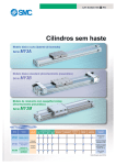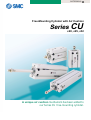
1
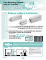
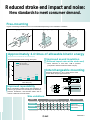
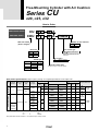
CAT.ES20-16 B
Free-Mounting Cylinder with Air Cushion
Seriesø20,CU
ø25, ø32
A unique air cushion mechanism has been added to
our Series CU free-mounting cylinder.
Free-Mounting Cylinder
with Air Cushion
Series CU
New air cushion mechanism
Free-mounting cylinder Series CU now
employs an air cushion mechanism.
Extended dimensions (compared to the standard
CU models) are hardly noticeable.
(with rubber bumper)
+1.5 to 7mm
• Overall height: +0 to 2mm
• Overall length:
CU hion
r cus
i
a
h
t
wi
No air cushion protrusion!
• Overall width: not affected
rub
CU
with per
um
ber b
(mm)
Bore Extended dimensions
size Length Height
ø20
2
7
ø25
0
1.5
ø32
0
4
Unique air cushion construction requires no cushion ring.
Elimination of the cushion ring used in conventional type air cushions has made it
possible to reduce the overall length of the cylinder while retaining all the advantages of
a compact profile.
Operating
principle
A + A'
A'
q When the piston is retracting, air is exhausted
through both A and A' until piston seal H
passes air passage A.
A
A'
R
H
Piston
seal
Features 1
A'
R
H
w After piston seal H has passed air passage A,
air is exhausted only through A'. The section
marked with slanted lines becomes a cushion
chamber, and an air cushion effect is achieved.
e When air is supplied for the piston extension,
the check valve opens and the piston extends
with no delay.
Reduced stroke end impact and noise:
New standards to meet consumer demand.
Free-mounting
3 types of mounting orientations can be accommodated depending on the installation conditions.
Axial mounting (tapped holes)
Vertical mounting (body through holes)
Lateral mounting (body through holes)
Approximately 2.4 times of allowable kinetic energy
(Compared to the old Series CU with rubber bumper)
Improved sound insulation
(Reduced impact noise at the stroke end)
Series CU comparison
: with air cushion
: with rubber bumper
3
• Noise reduction of more than 11dB is possible
(compared to Series CU20 with rubber bumper).
Interchangeable mounting
2
1
Mounting dimensions (J, K, R, and E) are the same
as the rubber bumper type Series CU.
0.70
0.11
20
0.28
0.44
0.29
0.18
R
Allowable kinetic energy (J)
Improved allowable kinetic energy absorption.
25
Bore size (mm)
32
E
When compared to rubber bumper type actuators, air
cushion type cylinders are less likely to be affected by
pressure fluctuations, and therefore better able to
achieve a stable and smooth stroke.
J
K
Improved repeatability
E
Size variations
Model
Standard strokes
20
C(D)U20
C(D)U25
C(D)U32
30
40
50
60
70
Auto switch
80
90 100
• ø20 to ø32
Direct mounting type
auto switch
Features 2
Free-Mounting Cylinder with Air Cushion
Series CU
ø20, ø25, ø32
How to Order
CU 32
CDU 32
Without auto switch
With auto switch
50 A
50 A F9BW
Number of auto switches
With auto switch
(built-in magnet)
Bore size
20
25
32
Nil
TN
TF
1 pc.
Without auto switch
Nil
25mm
∗ Select auto switch type from the
table below.
32mm
Type
2 pcs.
S
Auto switch type
20mm
Air cushion
Thread type
Symbol
Nil
A
With air cushion
Bore size
M threads ø20, ø25
Rc
NPT
Cylinder stroke (mm)
Refer to page 2 for standard strokes.
ø32
G
Type
Auto switch specifications: Refer to pages 7 through 11 for detailed specifications of auto switch units.
Solid state switch
Reed switch
Special
function
Electrical Indicator
entry
light
No
Wiring
(output)
2-wire
Grommet
—
Yes
—
Load voltage
DC
5V 100V
24V 12V or less
12V 100V
3-wire
(NPN equiv.) —
3-wire
(NPN)
3-wire
(PNP)
2-wire
Grommet
Diagnostic
indication
(
2-color
display
)
Yes
3-wire
(NPN)
3-wire
(PNP)
2-wire
AC
5V
—
5V
12V
12V
24V
5V
12V
12V
Note) Solid state switches marked "" are produced upon receipt of order.
Lead wire length (m)∗
0.5
(Nil)
3
(L)
5
(Z)
Applicable load
In-line
A90V
A90
—
IC
circuit
A93V
A93
—
—
A96V
A96
—
IC
circuit
F9NV
F9N
F9PV
F9P
F9BV
F9B
F9NWV
F9NW
F9PWV
F9PW
F9BWV
F9BW
Perpendicular
—
∗ Lead wire length symbols: 0.5m ............. Nil (Example) A93
3m ............. L
A93L
5m ............. Z
F9NWZ
1
Auto switch part no.
Relay
PLC
—
IC
circuit
—
IC
circuit
—
Relay
PLC
Free-Mounting Cylinder with Air Cushion
Series CU
Specifications
Type
Fluid
Proof pressure
Maximum operating pressure
Minimum operating pressure
Pneumatic (non-lube) type
Air
1.0MPa
0.7MPa
0.08MPa
Without auto switch: –10°C to 70°C (with no freezing)
With auto switch: –10°C to 60°C (with no freezing)
Male threads
JIS class 2
Ambient and
fluid temperature
Rod end thread
Rod end thread tolerance
Stroke length tolerance
Piston speed
+ 1.0
0
50 to 500mm/s
Effective Cushion Length
Bore size (mm)
Effective cushion length (mm)
20
6.6
25
6.7
32
7.7
Standard Strokes
Bore sizes (mm)
Standard strokes (mm)
20, 30, 40, 50, 60, 70, 80, 90, 100
20, 25, 32
∗ Intermediate strokes are also available upon receipt of order. Contact SMC.
Minimum stroke length is 20mm.
Tightening torque:
Bore sizes
(mm)
Refer to the below table
for mounting Series CU.
Theoretical Output
Hexagon socket
head cap screw Proper tightening
torque (N⋅m)
size (mm)
20, 25
32
5.10 ±10%
8.04 ±10%
M5
M6
OUT
IN
Unit: N
Bore size (mm) Operating direction
OUT
IN
OUT
IN
OUT
IN
20
Allowable kinetic energy
25
Refer to "Selection" on page 19
regarding allowable kinetic energy.
32
Operating pressure (MPa)
0.3
94.2
79.2
147
124
241
207
0.5
157
132
246
206
402
346
0.7
220
185
344
288
563
454
Weights
Basic weight
Bore size (mm)
20
25
32
Unit: g
Standard stroke (mm)
20
186
289
464
30
208
323
512
40
230
357
560
50
252
391
608
60
274
425
656
70
296
459
704
Additional weight
Bore size (mm)
80
318
493
752
90
340
527
800
100
362
561
848
20
25
32
Unit: g
Magnet
5
6
11
2
Series CU
Construction
u
t
!4
w
q
r
!3
!0
!2
i
o
!5
e
y
!1
Replacement parts: Seal kits
Parts list
No.
3
Note
Hard anodized
Bore size
Seal kit no.
ø20
CU20A-PS
1
Hard anodized
ø25
CU25A-PS
1
Clear chromated
ø32
CU32A-PS
Aluminum alloy
1
Chromated
Stainless steel
1
Carbon tool steel
1
Phosphate coated
Carbon steel
1
Nickel plated
—
(2)
Carbon steel
2
Material
Aluminum alloy
No. of pcs.
1
Description
Cylinder tube
2
Rod cover/Bearing
Aluminum alloy
3
Head cover
Aluminum alloy
4
Piston
5
Piston rod
6
Snap ring
7
Rod end nut
8
Cushion needle assembly
9
Steel ball
10
Magnet
11
Auto switch
12
13
1
Magnetic material
1
—
(2)
Piston gasket
NBR
1
Piston seal
NBR
2
14
Rod seal
NBR
1
15
Gasket
NBR
1
D- AF 9 type
Kit components
13, 14, and 15
Free-Mounting Cylinder with Air Cushion
Series CU
Dimensions
2-cushion needle
2-port
R
Q
2-øP through
E
GA
GB
4-NN
KA
B
J
JA
CA
K
C
CB
øD
MM
A
A'
H
Width across flats L
2-øP through
E
4-øT counterbore
S + Stroke
Z + Stroke
(mm)
Bore size
(mm)
20
25
32
Port size
A
A'
B
C
CA
CB
D
E
GA
GB
H
J
JA
M5 x 0.8
M5 x 0.8
Rc 1/8
12
15.5
19.5
14
18
22
26
32
40
42
50
62
20
25
31
22
25
31
8
10
12
9
10
11
29
32.5
35
27
22.5
25
19
23
27
16
20
24
12
15
19
Bore size
(mm)
K
KA
L
MM
NN
P
Q
R
T
S
Z
Standard strokes
20
25
32
30
38
48
5
6
7
5
6
8
M6 x 1.0
M8 x 1.25
M10 x 1.25
M5 x 0.8 with depth 8
M5 x 0.8 with depth 8
M6 x 1.0 with depth 9
5.5
5.5
6.6
13
23.5
29
16
20
24
9.3 with depth 8
9.3 with depth 9
11 with depth 11.5
53
51.5
56
72
74.5
83
20, 30, 40, 50, 60,
70, 80, 90, 100
4
Series CU
Auto Switch Proper Mounting Positions and Heights for Stroke End Detection
D-A9
D-F9
D-F9W
22 (24.5)
2.8
A
0.5
B
W
The dimension in ( ) is for D-A93 type.
D-A9V
D-F9V
D-F9WV
A
22 (20)
5 (7)
B
W
The dimension in ( ) is for D-F9V and D-F9WV.
(mm)
Bore size
(mm)
20
25
32
D-A9, D-A9V
W
A
B
D-F9, D-F9W
A
B
W
18
15
13 (10.5)
22
19
9
22
19
20
11
9 (6.5)
24.5
15
5
24.5
15
7
22.5
13.5
11.5 (9)
26.5
17.5
7.5
26.5
17.5
9.5
∗ Values in ( ) are dimensions for D-A93 type.
Operating Range
(mm)
Switch types
D-A9, D-A9V
D-F9, D-F9V
D-F9W, D-F9WV
Bore size
20
25
32
11
12.5
14
7
7
6.5
∗ Values in this table include hysteresis and are to be used as a guide
only. They do not guarantee an actual fixed range (expect approximately ±30% dispersion). Values may vary greatly depending on the
operating environment.
5
D-F9V, D-F9WV
A
B
W
11
Free-Mounting Cylinder with Air Cushion
Series CU
Auto Switch Rail Position
B
4-3
4-ø4.2
(mm)
A
Bore size (mm)
A
B
20
21
23
25
27
25
32
35
27
Caution – Proximity Installation
When free-mounting cylinders equipped with D-A9
or D-F9 type auto switches are used, be sure to
provide an extra clearance in addition to what is
suggested in the table at right. If the distance between
two cylinders is less than the noted value, auto
switches may malfunction. When for some reason you
cannot avoid installing cylinders closer than the
required clearance, install a steel plate or magnetic
shield plate (MU-SO25) on the side of the cylinder
facing the auto switches to shield them. (Contact SMC
for details.) Auto switches may malfunction if a
shielding plate is not used.
Bore size (mm)
Mounting clearance (mm)
20
40
25
46
32
56
Clearance
6
Series CU
Auto Switch Specifications
Auto Switch Common Specifications
Type
Reed switch
Solid state switch
None
3-wire: 100µA or less; 2-wire: 0.8mA or less
1.2ms
1ms or less
Leakage current
Operating time
Impact resistance
300m/s²
1000m/s²
50MΩ or more at 500VDC (between lead wire and case)
Insulation resistance
1000VAC for 1 minute
(between lead wire and case)
1500VAC for 1 minute
(between lead wire and case)
Withstand voltage
–10° to 60°C
Ambient temperature
IEC529 standard IP67, JIS C0920 watertight construction
Enclosure
Lead Wire Length
Contact Protection Box: CD-P11, CD-P12
Lead wire length indication
<Applicable switch types>
(Example)
D-F9P L
Lead wire length
Nil
L
Z
0.5m
3m
5m
Notes) • Lead wire length Z (5m) applicable auto switches
Solid state: All types are produced upon receipt of order.
• For solid state switches with flexible wire specification,
add "-61" at the end of the lead wire length.
D-A9, D-A9V
The above auto switches do not have built-in contact protection circuits.
A contact protection box should be used in any of the following
conditions, otherwise, the life of the contacts may be reduced (They may
stay on continuously):
1. Operated load is an induction load.
2. The length of wiring to the load is 5m or more.
3. The load voltage is 100VAC or 200VAC.
Specifications
CD-P11
100VAC
200VAC
Part no.
Load voltage
(Example) D-F9PL- 61
Flexible wire specification
Maximum load current
25mA
12.5mA
CD-P12
24VDC
50mA
∗ Lead wire length — Switch connection side: 0.5m
Load connection side: 0.5m
Internal circuits
CD-P11
Surge absorber
Choke
coil
OUT
Brown [Red]
OUT
Blue [Black]
CD-P12
Zener diodes
Choke
coil
OUT(+)
Brown [Red]
OUT(–)
Blue [Black]
Dimensions
Connection
To connect a switch unit to a contact protection box, connect the lead wire
from the side of the contact protection box marked SWITCH to the lead wire
coming out of the switch unit.
The switch unit should be kept as close as possible to the contact protection
box with a lead wire that is no more than 1 meter in length.
7
Series CU
Auto Switch Connections and Examples
Basic Wiring
Solid state 3-wire, NPN
Solid state 3-wire, PNP
Brown
[Red]
2-wire
<Reed switch>
Brown
[Red]
Main circuit
of switch
Blue
[Black]
Load
Brown
[Red]
Main circuit
of switch
Black
[White]
Indicator
light,
protection
circuit,
etc.
Load
Blue
[Black]
Blue
[Black]
Blue
[Black]
Brown
[Red]
(Power supplies for switch and load
are separate.)
Brown
Brown
[Red]
[Red]
Indicator
light,
protection
circuit,
etc.
Main circuit
of switch
Load
Black
[White]
Main circuit
of switch
Brown
[Red]
Load
Load
Black
[White]
Main circuit
of switch
2-wire
<Solid state>
Load
Load
Blue
[Black]
Blue
[Black]
Blue
[Black]
Examples of Connection to PLC
Source input specifications
3-wire, PNP Black
Sink input specifications
3-wire, NPN Black
[White] Input
[White] Input
Brown
[Red]
Switch
Blue
[Black]
2-wire
Switch
Brown
[Red]
Blue
[Black]
COM
PLC internal circuit
Brown
[Red]
The connection method will vary
depending on the applicable PLC
input specifications.
2-wire
Input
Switch
Blue
[Black]
COM
PLC internal circuit
Input
Switch
Blue
[Black]
Brown
[Red]
COM
PLC internal circuit
COM
PLC internal circuit
Connection Examples for AND (Series) and OR (Parallel)
3-wire
AND connection for NPN output
(performed with switches only)
AND connection for NPN output
(using relays)
Brown
[Red]
Switch 1
Blue
[Black]
Switch 2
Blue
[Black]
Black
[White]
Load
Relay
Relay
contact
Brown [Red]
Black
[White]
Relay
OR connection for NPN output
Brown
[Red]
Brown
[Red]
Black
Switch 1
[White] Load
Blue
[Black]
Brown
[Red] Black
Switch 2
[White]
Blue
[Black]
Switch 1
Black
[White]
Blue
[Black] Brown
[Red]
Switch 2
Load
Black
[White]
Blue
[Black]
The indicator lights will light up when
both switches are turned ON.
2-wire with 2-switch AND connection
Brown
[Red]
Switch 1
Switch 2
Blue
[Black]
Brown
[Red]
Blue
[Black]
Load
When two switches are
connected in series, a load
may malfunction because
the load voltage will decline when in the ON state.
The indicator lights will light
up if both of the switches
are in the ON state.
supply – Internal x 2 pcs.
Load voltage at ON = Power
voltage
voltage
drop
= 24V – 4V x 2 pcs.
= 16V
Example: Power supply is 24VDC
Internal voltage drop in switch is 4V
2-wire with 2-switch OR connection
Brown
[Red]
Switch 1
Blue
[Black]
Switch 2
Brown
[Red]
Blue
[Black]
Load
<Solid state>
When two switches
are connected in
parallel, a malfunction may occur because the load voltage will increase
when in the OFF
state.
Load
Load voltage at OFF = Leakage
current x 2 pcs. x impedance
= 1mA x 2 pcs. x 3kΩ
= 6V
Example: Load impedance is 3kΩ
Leakage current from switch is 1mA
<Reed switch>
Because there is no current
leakage, the load voltage will
not increase when turned
OFF. However, depending
on the number of switches in
the ON state, the indicator
lights may sometimes grow
dim or not light up because
of the dispersion and reduction of the current flowing to
the switches.
8
Reed Switches: Direct Mounting Type
D-A90(V), D-A93(V), D-A96(V)
Specifications
Auto switch part no.
D-A90
D-A90V
D-A93
D-A93V
D-A96
D-A96V
Electrical entry direction
In-line
Perpendicular
In-line
Perpendicular
In-line
Perpendicular
Wiring type
Applicable load
3-wire
2-wire
IC circuit, Relay,
PLC
Relay, PLC
IC circuit
24VDC/5 to 40mA
100VAC/5 to 20mA
4 to 8VDC/20mA
AC
Load
valtage
Load current range
and
Max. load current
24VDC or less/50mA
AC
48V DC or less/40mA
AC
100V DC
or less/20mA
Contact protection circuit
Internal resistance
Internal voltage drop
Internal circuits
Contact
protection
box
OUT(±)
Brown [Red]
2.4V or less
(to 20mA)
3V or less 2.7V or less
(to 40mA)
None
Indicator light
D-A90(V)
Reed switch
None
1Ω or less
(includes 3m
lead wire length)
0.8V or less
Red LED lights when ON
• Lead wire ........ Oil proof heavy duty vinyl cord: ø2.7, 0.5m
D-A90(V), D-A93(V): 0.18mm² x 2 cores (Brown, Blue [Red, Black])
D-A96(V): 0.15mm² x 3 cores (Brown, Black, Blue [Red, White, Black])
Note) Refer to page 7 for auto switch common specifications and lead wire length.
CD-P11
±
CD-P12
OUT( )
Blue [Black]
Weights
(g)
D-A93(V)
Brown
[Red]
Reed switch
LED
Resistor
Contact
protection
box
OUT(+)
Brown [Red]
Zener diode
Auto switch part no.
D-A90
D-A90V
D-A93V
D-A96
D-A96V
Lead wire length: 0.5m
7
7
6
7
8
8
Lead wire length: 3m
35
35
30
35
41
41
CD-P11
Blue
[Black]
CD-P12
OUT(–)
Blue [Black]
D-A96(V)
Reed switch
LED
DC(+)
Brown [Red]
Resistor
(+)
Load
OUT
Reverse
current
Black [White]
prevention
diode
DC(–)
Blue [Black]
DC power
(–)
Contact Protection Box
Type D-A9 switches do not have built-in contact
protection circuits. Use a contact protection box
with an induction load, when lead wires are 5
meters or longer, or with 100VAC.
Part no.
Voltage
Dimensions
D-A9
D-A9V
The dimension inside ( ) is for D-A93.
Contact protection box internal circuits
CD-P11
Choke coil
OUT Brown [Red]
Surge
absorber
Lead wire length
CD-P11 100VAC Switch connection side: 0.5m
CD-P12 24VDC Load connection side: 0.5m
Since D-A90(V) type switches have no particular
specified voltage below 100VAC, select a switch
type based on the voltage being used.
9
D-A93
OUT Blue [Black]
CD-P12
Zener Diode
Choke coil
OUT(+)
Brown [Red]
OUT(–)
Blue [Black]
Solid State Switches: Direct Mounting Type
D-F9N(V), D-F9P(V), D-F9B(V)
Specifications
Grommet
D-F9, D-F9V (with indicator light)
Auto switch part no.
D-F9N
D-F9NV
D-F9P
D-F9PV
D-F9B
D-F9BV
Electrical entry direction
In-line
Perpendicular
In-line
Perpendicular
In-line
Perpendicular
3-wire
Wiring type
2-wire
NPN
Output type
PNP
—
IC circuit, Relay, PLC
24VDC relay, PLC
Power supply voltage
5, 12, 24VDC (4.5 to 28V)
—
Current consumption
10mA or less
Applicable load
—
Load voltage
28VDC or less
—
24VDC (10 to 28VDC)
Load current
40mA or less
1.5V or less
(0.8V or less
at 10mA load current)
80mA or less
5 to 40mA
0.8V or less
4V or less
Internal voltage drop
100µA or less at 24VDC
Leakage current
0.8mA or less
Red LED lights when ON
Indicator light
• Lead wire ........ Oil proof heavy duty vinyl cord: ø2.7, 0.5m
D-F9N(V), D-F9P(V): 0.18mm² x 3 cores (Brown, Black, Blue [Red, White, Black])
D-F9B(V): 0.15mm² x 2 cores (Brown, Blue [Red, Black])
Note) Refer to page 7 for auto switch common specifications and lead wire length.
Internal circuits
Weights
(g)
D-F9N(V)
Main circuit
of switch
OUT
Lead wire length
(m)
Black [White]
DC(–)
Blue [Black]
D-F9N(V)
D-F9P(V)
0.5
7
7
6
3
37
37
31
5
61
61
51
Auto switch part no.
Brown [Red]
Dimensions
D-F9
D-F9P(V)
M2.5 x 4 Slotted set screw
DC(+)
2
Indicator light
2.8
Brown [Red]
OUT
Black [White]
2.6
Main circuit
of switch
D-F9B(V)
DC(–)
ø2.7
DC(+)
22
4
Blue [Black]
6
Most sensitive position
D-F9B(V)
OUT(+)
Brown [Red]
D-F9V
M2.5 x 4 Slotted set screw
Main circuit
of switch
4.3
Indicator light
2
20
3.1
6.2
3.8
ø2.7
2.8
Blue [Black]
4.6
OUT(–)
4
6
Most sensitive position
10
Solid State Switches: Direct Mounting Type
D-F9NW(V), D-F9PW(V), D-F9BW(V)
Specifications
Grommet
D-F9W, D-F9WV (with indicator light )
Auto switch part no. D-F9NW
In-line
Electrical entry direction
D-F9NWV D-F9PW
D-F9PWV
Perpendicular
Perpendicular
In-line
D-F9BW D-F9BWV
In-line
3-wire
Wiring type
NPN
Output type
Perpendicular
2-wire
—
PNP
IC circuit, Relay, PLC
24VDC relay, PLC
Power supply voltage
5, 12, 24VDC (4.5 to 28VDC)
—
Current consumption
10mA or less
Applicable load
—
24VDC (10 to 28VDC)
40mA or less
80mA or less
5 to 40mA
1.5V or less
(0.8V or less at 10mA load current)
0.8V or less
Load current
Internal voltage drop
—
28VDC or less
Load voltage
4V or less
0.8mA or less
Leakage current
100µA or less at 24VDC
Indicator light
Operating position .................. Red LED lights up
Optimum operating position … Green LED lights up
• Lead wire ........ Oil proof heavy duty vinyl cord: ø2.7, 0.5m
D-F9NW(V), D-F9PW(V): 0.18mm² x 3 cores (Brown, Black, Blue [Red, White, Black])
D-F9BW(V): 0.15mm² x 2 cores (Brown, Blue [Red, Black])
Note) Refer to page 7 for auto switch common specifications and lead wire length.
Internal circuits
Weights
D-F9NW(V)
(g)
DC(+)
Main circuit
of switch
Brown [Red]
Black [White]
D-F9BW(V)
D-F9NW(V)
D-F9PW(V)
0.5
7
7
7
3
34
34
32
5
56
56
52
Auto switch part no.
OUT
Lead wire length
(m)
DC(–)
Blue [Black]
Dimensions
D-F9PW(V)
DC(+)
M2.5 x 4 Slotted set screw
D-F9W
Indicator light
2
OUT
ø2.7
Main circuit
of switch
Brown [Red]
Black [White]
2.6
Blue [Black]
22
2.8
DC(–)
4
D-F9BW(V)
6
Most sensitive position
DC(+)
Main circuit
of switch
Brown [Red]
D-F9WV
M2.5 x 4 Slotted set screw
4.3
DC(–)
Indicator light
2
Blue [Black]
2.8
20
6.2
11
3.1
3.8
ø2.7
4.6
Indicator light
4
6
Most sensitive position
Series CU
Safety Instructions
These safety instructions are intended to prevent a hazardous situation and/or
equipment damage. These instructions indicate the level of potential hazard by a
label of "Caution", "Warning", or "Danger". To ensure safety, be sure to
observe ISO 4414 Note 1), JIS B 8370 Note 2) and other safety practices.
Caution : Operator error could result in injury or equipment damage.
Warning : Operator error could result in serious injury or loss of life.
Danger :
In extreme conditions, there is a possible result of serious injury or loss of life.
Note 1) ISO 4414: Pneumatic fluid power -- Recommendations for the application of equipment to transmission and control
systems.
Note 2) JIS B 8370: General Rules for Pneumatic Equipment
Warning
1. The compatibility of pneumatic equipment is the responsibility of the person
who designs the pneumatic system or decides its specifications.
Since the products specified here are used in various operating conditions, their compatibility with the
specific pneumatic system must be based on specifications or after analysis and/or tests to meet your
specific requirements.
2. Only trained personnel should operate pneumatically operated machinery and
equipment.
Compressed air can be dangerous if an operator is unfamiliar with it. Assembly, handling or repair of
pneumatic systems should be performed by trained and experienced operators.
3. Do not service machinery/equipment or attempt to remove components until
safety is confirmed.
1. Inspection and maintenance of machinery/equipment should only be performed after confirmation of
safe locked-out control positions.
2. When equipment is to be removed, confirm the safety process as mentioned above. Cut the supply
pressure for this equipment and exhaust all residual compressed air in the system.
3. Before machinery/equipment is restarted, take measures to prevent shooting-out of cylinder piston
rod, etc. (Bleed air into the system gradually to create back pressure.)
4. Contact SMC if the product is to be used in any of the following conditions:
1. Conditions and environments beyond the given specifications, or if product is used outdoors.
2. Installation on equipment in conjunction with atomic energy, railway, air navigation, vehicles, medical
equipment, food and beverages, recreation equipment, emergency stop circuits, press applications,
or safety equipment.
3. An application which has the possibility of having negative effects on people, property, or animals,
requiring special safety analysis.
12
Series CU
Actuator Precautions 1
Be sure to read before handling.
Design
Warning
Design
Warning
1. There is a danger of sudden or erratic action
by cylinders if sliding parts of machinery are
twisted and changes in forces occur.
9. Consider the action when operation is restarted after an emergency stop or an abnormal stop.
In such cases, bodily injury may occur, e.g., by catching hands
or feet in the machinery, or damage to the machinery itself may
occur. Therefore, the machinery should be adjusted to operate
smoothly and designed to prevent such dangers.
Design machinery so that bodily injury or equipment damage
will not occur upon restart of operation.
When the cylinder has to be reset at the starting position, install
safe manual control equipment.
2. A protective cover is recommended to minimize the risk of personal injury.
If a driven object and moving parts of a cylinder pose a serious
danger of bodily injury, design the structure to avoid contact
with the human body.
3. Securely tighten all stationary parts and
connected parts so that they will not become
loose.
Especially when a cylinder operates with high frequency or is
installed where there is a lot of vibration, ensure that all parts
remain secure.
4. A deceleration circuit or shock absorber may
be required.
When a driven object is operated at high speed or the load is
heavy, a cylinder’s cushion will not be sufficient to absorb the
impact. Install a deceleration circuit to reduce the speed before
cushioning, or install an external shock absorber to relieve the
impact. In this case, the rigidity of the machinery should also be
examined.
5. Take into account a possible drop in operating pressure due to a power outage.
When a cylinder is used as a clamping mechanism, there is a
danger of work pieces dropping if there is a decrease in
clamping force due to a drop in circuit pressure caused by a
power outage. Therefore, safety equipment should be installed
to prevent damage to machinery and bodily injury. Suspension
mechanisms and lifting devices also require drop prevention
measures.
6. Take into account a possible loss of power
source.
Measures should be taken to protect against bodily injury and
equipment damage in the event that there is a loss of power to
equipment controlled by air pressure, electricity, or hydraulics.
7. Design circuitry to prevent sudden lurching
of driven objects.
Take special care when a cylinder is operated by an exhaust
center type directional control valve or when it is starting up
after residual pressure is exhausted from the circuit. The piston
and its driven object will lurch at high speed if pressure is
applied to one side of the cylinder because of the absence of
air pressure inside the cylinder. Therefore, equipment should
be selected and circuits designed to prevent sudden lurching
because of the danger of bodily injury, particularly to limbs,
and/or damage to equipment when this occurs.
8. Take into account emergency stops.
Design the system so that bodily injury and/or damage to
machinery and equipment will not occur when machinery is
stopped by a manual emergency stop or a safety device
triggered by abnormal conditions.
13
Selection
Warning
1. Confirm the specifications.
The products featured in this catalog are designed for use in
industrial compressed air systems. If the products are used in
conditions where pressure and/or temperature are outside the
range of specifications, damage and/or malfunctions may
occur. Do not use in these conditions. (Refer to specifications.)
Consult with SMC if fluid other than compressed air to be used.
2. Intermediate stops
When intermediate stopping of a cylinder piston is performed
with a 3-position closed center type directional control valve, it
is difficult to achieve stopping positions as accurately and
precisely as with hydraulic pressure due to the compressibility
of air.
Furthermore, since valves and cylinders are not guaranteed for
zero air leakage, it may not be possible to hold a stopped
position for an extended period of time. Contact SMC in case it
is necessary to hold a stopped position for an extended period.
Caution
1. Operate within the limits of the maximum
usable stroke.
The piston rod will be damaged if operated beyond the maximum stroke. Operate within the standard stroke range.
2. Operate the piston in such a way that collision
damage will not occur at the stroke end.
3. Use a speed controller to adjust the cylinder
drive speed, gradually increasing from a low
speed to the desired speed setting.
Series CU
Actuator Precautions 2
Be sure to read before handling.
Mounting
Cushion
Caution
Caution
1. Be certain to align the rod center of the piston
axis with the load and direction of movement
when connecting.
When a cylinder is not properly aligned, the rod and tube may
be twisted. This can cause wear on areas such as the inner
tube surface, bushings, rod surface, seals, and cause damage
to these areas.
2. When an external guide is used, connect the
piston rod end and the load in such a way
that there is no interference at any point
within the stroke.
3. Do not scratch or gouge the cylinder tube or
the sliding parts of the piston rod by striking
or grasping them with other objects.
Cylinder bores are manufactured to precise tolerances, so that
even a slight deformation may cause faulty operation.
Also, scratches or gouges in the piston rod may lead to
damaged seals and cause air leakage.
4. Prevent the sticking (through friction) of
rotating parts.
Prevent the sticking of rotating parts (pins etc.) by applying
grease.
5. Do not use until you can verify that equipment
can operate properly.
1. Readjust using the cushion needle.
Cushion needles are fully closed at the time of shipment. When
the cylinder is put into service, the cushion needles should be
readjusted based on factors such as the size of the load and
the operating speed. When the cushion needles are turned
clockwise, restriction of the air flow becomes greater and thus
the cushion effect also increases.
2. Do not operate with the cushion needles fully
closed.
3. Adjust the cushion needles by gradually
opening from the closed condition to a desired cushion speed.
Lubrication
Caution
1. Lubrication of non-lube type cylinder
The cylinder is lubricated for life at the factory and can be used
without any further lubrication.
However, in the event that the cylinder is lubricated additionally,
be sure to use class 1 turbine oil (with no additives) ISO VG32.
Stopping lubrication later may lead to malfunctions because the
new lubricant will cancel out the original lubricant. Therefore,
lubrication must be continued once it has been started.
Following mounting, repairs, or conversions, verify correct
mounting by conducting suitable function and leakage tests
after piping and power connections have been made.
6. Instruction manual
The product should be mounted and operated after thoroughly
reading the manual and understanding its contents.
Keep the instruction manual where it can be readily referred to
as needed.
Piping
Warning
1. Use clean air.
Do not use compressed air containing chemicals, synthetic oils
containing organic solvents, salt, or corrosive gases, as this can
cause damage or malfunctions.
Caution
1. Install air filters.
Caution
1. Preparation before piping
Before piping is connected, it should be thoroughly flushed out
with air or water to remove chips, cutting oil, and other debris.
2. Wrapping of sealant tape
When screwing together pipes and fittings, be certain that chips
from the pipe threads and sealing material do not get inside the
piping.
Also, when sealant tape is used, leave 1.5 to 2 thread ridges
exposed at the end of the threads.
Wrapping direction
Ex
po
se
Air Supply
ap
pro
x.
Sealant tape
Install air filters at the inlet side of valves. The filtration degree
should be 5µm or finer.
2. Install an after-cooler, air dryer, or water
separator (Drain Catch).
Air that includes excessive drainage or condensate may cause
malfunction of valves and other pneumatic equipment. To
prevent this, install an after-cooler, air dryer, or water separator
(Drain Catch).
3. Use the product within the specified range of
fluid and ambient temperature.
Take measures to prevent freezing when below 5°C, since
moisture in circuits can freeze and cause damage to seals and
lead to malfunctions.
Refer to SMC’s “Air Preparation System” catalog for further details
on compressed air quality.
2t
hre
ad
s
14
Series CU
Actuator Precautions 3
Be sure to read before handling.
Operating Environment
Warning
1. Do not use in environments where there is a
danger of corrosion.
2. In dusty conditions or where water or oil
splashing is a regular occurrence, protect the
rod by installing a rod cover.
3. When using auto switches, do not operate in
an environment where there are strong
magnetic fields.
Maintenance
Warning
1. Perform maintenance inspection and service
according to the procedures indicated in the
instruction manual.
Improper handling and maintenance may cause malfunctioning
and damage of machinery or equipment to occur.
2. Removal of components and supply/exhaust
of compressed air
Before any machinery or equipment is removed, first ensure
that the appropriate measures are in place to prevent the fall or
erratic movement of driven objects and equipment. Then cut off
the electric power and reduce the pressure in the system to
zero.
When machinery is restarted, proceed with caution after
confirming that appropriate measures are in place to prevent
cylinders from lurching.
Caution
1. Filter drainage
Drain out condensate from air filters regularly.
15
Series CU
Auto Switch Precautions 1
Be sure to read before handling.
Design and Selection
Warning
1. Confirm the specifications.
Read the specifications carefully and use the product appropriately. The product may be damaged or malfunction if it is used
outside the range of specifications for load current, voltage,
temperature or impact.
2. Take precautions when multiple cylinders are
used close together.
When two or more auto switch cylinders are lined up in close
proximity to each other, magnetic field interference may cause
the switches to malfunction. Maintain a minimum cylinder
separation of 40mm. (When the allowable interval is specified
for each cylinder series, use the indicated value.)
3. Monitor the length of time that a switch is on
at an intermediate stroke position.
When an auto switch is placed at an intermediate position of
the stroke and a load is driven at the time the piston passes, the
auto switch will operate, but if the speed is too great the
operating time will be shortened and the load may not operate
properly. The maximum detectable piston speed is:
V(mm/s) =
Auto switch operating range (mm)
Load operating time (ms)
x 1000
4. Keep wiring as short as possible.
• Similarly, when operating below a specified voltage, it is
possible that the load may be ineffective even though the
auto switch function is normal. Therefore, the formula
below should be satisfied after confirming the minimum
operating voltage of the load.
Supply voltage –
Internal voltage
Minimum operating
drop of switch > voltage of load
2) If the internal resistance of a light emitting diode causes a
problem, select a switch without an indicator light (D-A90, DA90V).
<Solid state switches>
3) Generally, the internal voltage drop will be greater with a 2wire solid state auto switch than with a reed switch. Take the
same precautions as in 1) above.
Also, note that a 12VDC relay is not applicable.
6. Monitor leakage current.
<Solid state switches>
With a 2-wire solid state auto switch, current (leakage current)
flows to the load to operate the internal circuit even when in the
off state.
If the condition given in the below formula is not met, the switch
will not reset correctly (it stays on).
Current to operate load (off condition) > Leakage current
<Reed switches>
As the length of the wiring to a load gets longer, the rush
current at switching on becomes greater, and this may shorten
the product’s life. (The switch will stay on all the time.)
Use a contact protection box when the wire length is 5m or
longer.
<Solid state switches>
Although wire length should not affect switch function, use a
wire that is 100m or shorter.
5. Monitor the internal voltage drop of the switch.
<Reed switches>
1) Switches with an indicator light (except D-A96, D-A96V)
• If auto switches are connected in series as shown below,
take note that there will be a large voltage drop because of
internal resistance in the light emitting diodes. (Refer to
internal voltage drop in the auto switch specifications.)
[The voltage drop will be “n” times larger when “n” auto
switches are connected.]
Even though an auto switch operates normally, the load
may not operate.
Load
Use a 3-wire switch if this condition cannot be satisfied.
Moreover, leakage current flow to the load will be “n” times
larger when “n” auto switches are connected in parallel.
7. Do not use a load that generates surge voltage.
<Reed switches>
If driving a load that generates surge voltage, such as a relay,
use a switch with a built-in contact protection circuit or a contact
protection box.
<Solid state switches>
Although a zener diode for surge protection is connected at the
output side of a solid state auto switch, damage may still occur
if a surge is applied repeatedly. When directly driving a load
which generates surge, such as a relay or solenoid valve, use a
type of switch with a built-in surge absorbing element.
8. Cautions for use in an interlock circuit
When an auto switch is used for an interlock signal requiring
high reliability, devise a double interlock system to safeguard
against malfunctions by providing a mechanical protection
function, or by also using another switch (sensor) together with
the auto switch.
Also, perform periodic maintenance inspections and confirm
proper operation.
9. Ensure sufficient clearance for maintenance
activities.
When designing an application, be sure to allow sufficient
clearance for maintenance and inspections.
16
Series CU
Auto Switch Precautions 2
Be sure to read before handling.
Mounting and Adjustment
Warning
Warning
1. Do not drop or bump.
Do not drop, bump, or apply excessive impacts (300m/s² or
more for reed switches and 1000m/s² or more for solid state
switches) while handling. Although the body of the switch may
not be damaged, the inside of the switch could be damaged
and cause a malfunction.
2. Do not carry a cylinder by the auto switch
lead wires.
Never carry a cylinder by its lead wires. This may not only
cause broken lead wires, but it may cause internal elements of
the switch to be damaged by the stress.
3. Mount switches using the proper tightening
torque.
When a switch is tightened beyond the range of tightening
torque, the mounting screws, mounting bracket, or switch may
be damaged.
On the other hand, tightening below the range of tightening
torque may allow the switch to slip out of position.
4. Mount a switch at the center of the operating
range.
Adjust the mounting position of an auto switch so that the
piston stops at the center of the operating range (the range in
which a switch is on). (The mounting positions shown in the
catalog indicate the optimum position at the stroke end.) If
mounted at the end of the operating range (around the
borderline of on and off), the operation will be unstable.
Wiring
Warning
1. Avoid repeatedly bending or stretching lead
wires.
Broken lead wires will result from repeatedly applying bending
stress or stretching force to the lead wires.
2. Be sure to connect the load before power is
applied.
<2-wire type>
If the power is turned on when an auto switch is not connected
to a load, the switch will be instantly damaged because of
excess current.
3. Confirm proper insulation of wiring.
Be certain that there is no faulty wiring insulation (such as
contact with other circuits, ground fault, improper insulation
between terminals, etc.). Damage may occur due to excess
current flow into a switch.
4. Do not wire in conjunction with power lines
or high voltage lines.
Wire separately from power lines or high voltage lines, avoiding
parallel wiring or wiring in the same conduit with these lines.
Control circuits containing auto switches may malfunction due
to noise from these other lines.
17
Wiring
5. Do not allow short circuiting of loads.
<Reed switches>
If the power is turned on with a load in a short circuited
condition, the switch will be instantly damaged because of
excess current flow into the switch.
<Solid state switches>
D-F9(V), D-F9W(V) and all models of PNP output type
switches do not have built-in short circuit protection circuits. If
loads are short circuited, the switches will be instantly
damaged, as in the case of reed switches.
∗ Take special care to avoid reverse wiring with the brown [red]
power supply line and the black [white] output line on 3-wire
type switches.
6. Avoid incorrect wiring.
<Reed switches>
A 24VDC switch with indicator light has polarity. The brown [red]
lead wire is (+), and the blue [black] lead wire is (–).
1) If connections are reversed, the switch will still operate, but
the light emitting diode will not light up.
Also note that a current greater than the maximum specified
one will damage a light emitting diode and make it
inoperable.
Applicable models: D-A93, D-A93V
<Solid state switches>
1) Even if connections are reversed on a 2-wire type switch, the
switch will not be damaged because it is protected by a
protection circuit, but it will remain in a normally on state.
However, it is still necessary to avoid reversed connections
since the switch could be damaged by a load short circuit in
this condition.
∗ 2) Even if (+) and (–) power supply line connections are
reversed on a 3-wire type switch, the switch will still be
protected by a protection circuit. However, if the (+) power
supply line is connected to the blue [black] wire and the (–)
power supply line is connected to the black [white] wire, the
switch will be damaged.
∗ Lead wire color changes
Lead wire colors of SMC switches have been changed in order to
meet NECA Standard 0402 for production beginning September,
1996 and thereafter. Please refer to the tables provided.
Special care should be taken regarding wire polarity during the
time that the old colors still coexist with the new colors.
2-wire
Output (+)
Output (–)
3-wire
Old
Red
Black
New
Brown
Blue
Solid state
with diagnostic output
Old
Red
Power supply GND Black
Output
White
Power supply (+)
Diagnostic output
Old
Red
Power supply GND Black
Output
White
Power supply (+)
New
Brown
Blue
Black
Solid state with latch
type diagnostic output
New
Brown
Blue
Black
Yellow Orange
New
Brown
Blue
Black
Output
Old
Red
Black
White
Latch type
diagnostic output
Yellow Orange
Power supply (+)
Power supply GND
Series CU
Auto Switch Precautions 3
Be sure to read before handling.
Operating Environment
Warning
1. Never use in the presence of explosive gases.
The construction of our auto switches does not make them
explosionproof. Never use them in the presence of an explosive
gas, as this may cause a serious explosion
2. Do not use in an area where a magnetic field
is generated.
Auto switches will malfunction or magnets inside cylinders will
become demagnetized if used in such an environment.
(Consult with SMC regarding the availability of magnetic field
resistant auto switches.)
3. Do not use in an environment where the auto
switch will be continually exposed to water.
Switches satisfy IEC standard IP67 construction (JIS C0920:
watertight construction). Nevertheless, they should not be used
in applications where they are continually exposed to water
splash or spray. This may cause deterioration of the insulation
or swelling of the potting resin inside switches and may lead to
a malfunction.
Maintenance
Warning
1. Perform the following maintenance inspection and services periodically in order to prevent possible danger due to unexpected auto
switch malfunction.
1) Securely tighten switch mounting screws.
If screws become loose or the mounting position is
dislocated, retighten screws securely after readjusting the
mounting position.
2) Confirm that there is no damage to lead wires.
To prevent faulty insulation, replace switches or repair lead
wires if damage is discovered.
3) Confirm that the green light on the 2-color indicator type
switch lights up.
Confirm that the Green LED is ON when stopped at the set
position. If the Red LED is ON when stopped at the set
position, the mounting position is not appropriate. Readjust
the mounting position until the Green LED lights up.
4. Do not use in an environment laden with oil
or chemicals.
Consult with SMC if auto switches will be used in an
environment laden with coolants, cleaning solvents, various oils
or chemicals. If auto switches are used under these conditions
for even a short time, they may be adversely affected by a
deterioration of the insulation, a malfunction due to swelling of
the potting resin, or hardening of the lead wires.
Other
Warning
1. Consult with SMC concerning water resistance, elasticity of lead wires, and usage at
welding sites.
5. Do not use in an environment with temperature
cycles.
Consult with SMC if switches are to be used where there are
temperature cycles other than normal temperature changes, as
they may be adversely affected internally.
6. Do not use in an environment where there is
excessive impact shock.
<Reed switches>
When excessive impact (300m/s² or more) is applied to a reed
switch during operation, the contact point may malfunction and
generate or cut off a signal momentarily (1ms or less). Consult
with SMC regarding the need to use a solid state switch
depending on the environment.
7. Do not use in an area where surges are
generated.
<Solid state switch>
When there are units (such as solenoid type lifters, high
frequency induction furnaces, motors) that generate a large
amount of surge in the area around cylinders with solid state
auto switches, their proximity or pressure may cause
deterioration or damage to the internal circuit elements of the
switches. Avoid and protect against sources of surge
generation and crossed lines.
8. Avoid close contact with accumulated iron
waste or magnetic substances.
When a large accumulated amount of ferrous waste such as
machining chips or welding spatter, or a magnetic substance
(something attracted by a magnet) is brought into close
proximity to an cylinder with auto switches, this may cause the
auto switches to malfunction due to a loss of the magnetic force
inside the cylinder.
18
Series CU
Specific Product Precautions
Be sure to read before handling.
Refer to pages 12 through 18 for Safety Instructions, Actuator Precautions, and Auto Switch Precautions.
Installation and Removal of Snap Rings
Selection
Caution
Caution
1. Use appropriate pliers (C-type snap ring installing
tool) for installation and removal of snap rings.
2. Even when using appropriate pliers (C-type snap ring
installing tool), proceed with caution as there is a
danger of the snap ring flying off the end of the pliers
(tool) and causing bodily injury or damage to nearby
equipment. After installation, make sure that the snap
ring is securely seated into the snap ring groove
before supplying air.
3. Adjust the cushion needle to reduce excessive
kinetic energy from the piston impact at the stroke
end by allowing it to absorb sufficient kinetic
energy during the cushion stroke.
If due to improper adjustment, the piston impacts the stroke
end with excessive kinetic energy (values above those given in
Table 1), an excessive impact will occur and this may cause
damage to equipment.
Table 1. Allowable kinetic energy at piston impact
20
25
Piston speed
Mounting
Allowable kinetic energy
Caution
1. Refer to the below table for mounting cylinders.
If operated beyond the limiting ranges, equipment life may be
reduced or damage to equipment may occur.
Hexagon socket head cap screw Proper tightening torque
(mm)
(N⋅m)
20, 25
32
5.10 ±10%
8.04 ±10%
M5
M6
0.15
4. Strictly observe the limiting ranges for the piston rod
lateral load (Graph 2).
Tightening torque
Bore sizes
(mm)
50 to 500mm/s
0.09
0.055
Unit: J
32
Piston rod lateral load (Graph 2)
5.00
4.50
4.00
Caution
1. Operate the cylinder to the stroke end.
When the stroke is restricted by an external stopper or a
clamped work piece, sufficient cushioning and noise reduction
may not be achieved.
2. Strictly observe the limiting ranges for load weight
and maximum speed (Graph 1). Also, the limiting
ranges provided here are based on the condition
that the cylinder is operated to the stroke end with a
proper cushion needle adjustment.
If operated beyond the limiting ranges, excessive impact will
occur and this may cause damage to equipment.
: Operating pressure 0.5MPa
: Operating pressure 0.4MPa
Graph 1
Lateral load (N)
Selection
3.50
3.00
ø32
2.50
2.00
ø25
1.50
ø20
1.00
0.50
0.00
20
30
60
70
Stroke (mm)
80
90
100
Cushion Needle Adjustment
Caution
20.00
ø20 to ø32
Load weight (kg)
50
1. Keep the adjustment range for the cushion needle
between the fully closed position and the rotations
shown below.
25.00
10.00
ø32
ø25
ø20
0.00
10
100
Maximum speed (mm/s)
Rotations
2.5 rotations or less
Use a 3mm flat head watchmakers screwdriver to adjust the
cushion needle. The adjustment range for the cushion needle
must be between the fully closed position and the open position
ranges indicated in the above table. A retaining mechanism
prevents the cushion needle from slipping out; however, it may
spring out during operation if it is rotated beyond the ranges
shown above.
15.00
5.00
19
40
1000
SMC'S GLOBAL MANUFACTURING, DISTRIBUTION AND SERVICE NETWORK
EUROPE
EUROPE
NORTH AMERICA
AUSTRIA
SMC Pneumatik GmbH
CZECH
SMC Industrial Automation CZ s.r.o.
DENMARK
SMC Pneumatik A/S
FINLAND
SMC Pneumatics Finland Oy
FRANCE
SMC Pneumatique SA
GERMANY
SMC Pneumatik GmbH
HUNGARY
SMC Hungary Ipari Automatizálási Kft.
IRELAND
SMC Pneumatics (Ireland) Ltd.
ITALY
SMC Italia S.p.A.
NETHERLANDS
SMC Pnuematics BV.
NORWAY
SMC Pneumatics Norway A/S
POLAND
SMC Industrial Automation Polska Sp.z.o.o.
ROMANIA
SMC Romania s.r.l.
RUSSIA
SMC Pneumatik LLC.
SLOVAKIA
SMC Priemyselná automatizáciá, s.r.o.
SLOVENIA
SMC Industrijska Avtomatika d.o.o.
SPAIN/PORTUGAL
SMC España, S.A.
SWEDEN
SMC Pneumatics Sweden AB
SWITZERLAND
SMC Pneumatik AG.
UK
SMC Pneumatics (U.K.) Ltd.
CANADA
SMC Pneumatics (Canada) Ltd.
MEXICO
SMC Corporation (Mexico) S.A. de C.V.
USA
SMC Corporation of America
SOUTH AMERICA
ASIA
CHINA
SMC (China) Co., Ltd.
HONG KONG
SMC Pneumatics (Hong Kong) Ltd.
INDIA
SMC Pneumatics (India) Pvt. Ltd.
MALAYSIA
SMC Malaysia (S.E.A.) Sdn. Bhd.
PHILIPPINES
SMC Pneumatics (Philippines), Inc.
SINGAPORE
SMC Pneumatics (S.E.A.) Pte. Ltd.
SOUTH KOREA
SMC Pneumatics Korea Co., Ltd.
TAIWAN
SMC Pneumatics (Taiwan) Co., Ltd.
THAILAND
SMC Thailand Ltd.
ARGENTINA
SMC Argentina S.A.
BOLIVIA
SMC Pneumatics Bolivia S.R.L.
BRAZIL
SMC Pneumaticos Do Brazil Ltda.
CHILE
SMC Pneumatics (Chile) S.A.
VENEZUELA
SMC Neumatica Venezuela S.A.
OCEANIA
AUSTRALIA
SMC Pneumatics (Australia) Pty. Ltd.
NEW ZEALAND
SMC Pneumatics (N.Z.) Ltd.
1-16-4 Shimbashi, Minato-ku, Tokyo 105-0004, JAPAN
Tel: 03-3502-2740 Fax: 03-3508-2480
URL http://www.smcworld.com
© 2001 SMC CORPORATION All Rights Reserved
1st printing September, 2001
D-SMC.L.A. P-80 (JT)
This catalog is printed on recycled paper with concern for the global environment.
All specifications in this catalog are subject to change without notice.
Printed in Japan.