1
1BChapter 2: Installation
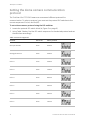
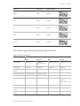
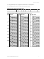
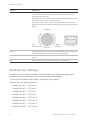
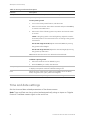
Figure 6: Example of setting DIP switches for the dome camera site ID 210 (128 + 64 + 16 + 2)
22-pin connector description
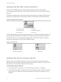
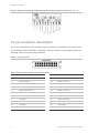
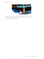
The 22-pin connector for I/O interface cable connection is located on the back plate
of the dome camera. See Table 7 below for the pin locations if you need to attach, for
example, alarm input and output devices.
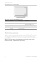
Figure 7: 22-pin connector
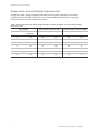
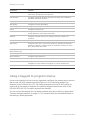
Table 7: Dome camera’s 22-pin connector description
Pin
Description
Pin
Description
1
Power In AC 24 – 1
12
Alarm Contact 1
2
Alarm Relay NC
13
Alarm Contact 2
3
Power In AC 24 – 2
14
Alarm Contact 3
4
Alarm Relay NO
15
Alarm Contact 4
5
Power Earth Ground
16
Alarm Contact 5
6
Relay Com
17
Alarm Contact 6
7
Control T+
18
Alarm Contact 7
8
Control R-
19
Alarm Contact 8
9
Control T-
20
Alarm Contact GND
10
Control R+
21
Video GND
11
ISOG
22
Video POS
14
TruVision Mini PTZ 12X Camera User Manual