1
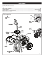
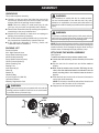
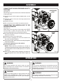
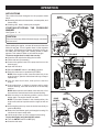
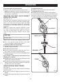
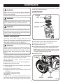
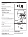
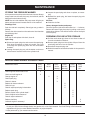
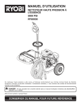
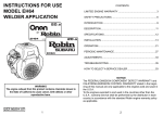
OPERATOR’S MANUAL
GASOLINE PRESSURE WASHER
3000 PSI
RY80030
Your pressure washer has been engineered and manufactured to Ryobi’s high standard for dependability, ease of operation,
and operator safety. When properly cared for, it will give you years of rugged, trouble-free performance.
DANGER: You WILL be KILLED or SERIOUSLY HURT if you do not follow the instructions in this operator’s
manual.
Thank you for buying a Ryobi product.
SAVE THIS MANUAL FOR FUTURE REFERENCE
TABLE OF CONTENTS
n Introduction .......................................................................................................................................................................2
�n Important Safety Instructions ............................................................................................................................................3
�n Specific Safety Rules ........................................................................................................................................................4
�n Symbols......................................................................................................................................................................... 5-6
�n Features......................................................................................................................................................................... 7-8
�n Assembly ..................................................................................................................................................................... 9-12
�n Operation................................................................................................................................................................... 12-15
�n Maintenance .............................................................................................................................................................. 16-18
n Troubleshooting .............................................................................................................................................................. 19
n Warranty .................................................................................................................................................................... 21-25
�n Parts Ordering / Service ................................................................................................................................................. 26
INTRODUCTION
This tool has many features for making its use more pleasant and enjoyable. Safety, performance, and dependability have
been given top priority in the design of this product making it easy to maintain and operate.
2
IMPORTANT SAFETY INSTRUCTIONS
n NEVER STAND ON TOOL. Serious injury could occur
if the tool is tipped.
n CHECK DAMAGED PARTS. Before further use of the
tool, a guard or other part that is damaged should
be carefully checked to determine that it will operate
properly and perform its intended function. Check for
alignment of moving parts, binding of moving parts,
breakage of parts, mounting and any other conditions
that may affect its operation. A guard or other part that
is damaged must be properly repaired or replaced by an
authorized service center to avoid risk of personal injury.
n NEVER LEAVE TOOL RUNNING UNATTENDED.
TURN POWER OFF. Don't leave tool until it comes to
a complete stop.
n KEEP THE ENGINE FREE OF GRASS, LEAVES, OR
GREASE to reduce the chance of a fire hazard.
n KEEP THE EXHAUST PIPE FREE OF FOREIGN
OBJECTS.
n FOLLOW MANUFACTURER’S RECOMMENDATIONS
FOR SAFE LOADING, UNLOADING, TRANSPORT, AND
STORAGE OF MACHINE.
n BE THOROUGHLY FAMILIAR WITH CONTROLS.
Know how to stop the product and bleed pressure
quickly.
n KEEP TOOL DRY, CLEAN, AND FREE FROM OIL
AND GREASE. Always use a clean cloth when cleaning.
Never use brake fluids, gasoline, petroleum-based
products, or any solvents to clean tool.
n STAY ALERT AND EXERCISE CONTROL. Watch what
you are doing and use common sense. Do not operate
tool when you are tired. Do not rush.
n DO NOT OPERATE THE PRODUCT WHILE UNDER
THE INFLUENCE OF DRUGS, ALCOHOL, OR ANY
MEDICATION.
n CHECK THE WORK AREA BEFORE EACH USE.
Remove all objects such as rocks, broken glass, nails,
wire, or string which can be thrown or become entangled
in the machine.
n DO NOT USE TOOL IF SWITCH DOES NOT TURN
IT ON AND OFF. Have defective switches replaced by
an authorized service center.
n BEFORE CLEANING, REPAIRING, OR INSPECTING,
shut off the engine and make certain all moving parts have
stopped. Disconnect the spark plug wire, and keep the
wire away from the plug to prevent accidental starting.
n AVOID DANGEROUS ENVIRONMENT. Don’t use in
damp or wet locations or expose to rain. Keep work
area well lit.
n NEVER USE IN AN EXPLOSIVE ATMOSPHERE.
Normal sparking of the motor could ignite fumes.
n DO NOT OPERATE WHILE SMOKING OR NEAR AN
OPEN FLAME.
n DO NOT OPERATE AROUND dry brush, twigs, cloth
rags, or other flammable materials.
n WARNING: RISK OF INJECTION OR INJURY – Do
not direct discharge stream at persons.
WARNING:
Read and understand all instructions. Failure to follow
all instructions listed below may result in electric shock,
fire and/or carbon monoxide poisoning which will cause
death or serious personal injury.
READ ALL INSTRUCTIONS BEFORE USING
THIS PRODUCT
n KNOW YOUR TOOL. Read the operator's manual
carefully. Learn the machine's applications and
limitations as well as the specific potential hazards
related to this tool.
n KEEP GUARDS IN PLACE and in working order. Never
operate the tool with any guard or cover removed.
Make sure all guards are operating properly before
each use.
n REMOVE ADJUSTING KEYS AND WRENCHES.
Form habit of checking to see that keys and adjusting
wrenches are removed from tool before turning it on.
n TO REDUCE THE RISK OF INJURY, keep children and
visitors away. All visitors should wear safety glasses
and be kept a safe distance from work area.
n KEEP THE AREA OF OPERATION CLEAR OF ALL
PERSONS, particularly small children, and pets.
n DO NOT OPERATE THE ENGINE IN A CONFINED
SPACE where dangerous carbon monoxide fumes can
collect. Carbon monoxide, a colorless, odorless, and
extremely dangerous gas can cause unconsciousness
or death.
n USE RIGHT TOOL. Don't force tool or attachment
to do a job it was not designed for. Don't use it for a
purpose not intended.
n DRESS PROPERLY. Do not wear loose clothing, gloves,
neckties, or jewelry. They can get caught and draw you
into moving parts. Rubber gloves and nonskid footwear
are recommended when working outdoors. Also wear
protective hair covering to contain long hair.
n DO NOT OPERATE THE EQUIPMENT WHILE BAREFOOT OR WHEN WEARING SANDALS OR SIMILAR
LIGHTWEIGHT FOOTWEAR. Wear protective footwear
that will protect your feet and improve your footing on
slippery surfaces.
n EXERCISE CAUTION TO AVOID SLIPPING OR
FALLING.
n ALWAYS WEAR SAFETY GLASSES WITH SIDE
SHIELDS. Everyday eyeglasses have only impactresistant lenses; they are NOT safety glasses.
n DON'T OVERREACH OR STAND ON UNSTABLE
SUPPORT. Keep proper footing and balance at all
times.
n USE ONLY RECOMMENDED ACCESSORIES. The use
of improper accessories may cause risk of injury.
3
SPECIFIC SAFETY RULES
n ALWAYS REFUEL OUTDOORS. Never refuel indoors or
in a poorly ventilated area.
n NEVER DIRECT A WATER STREAM TOWARDS
PEOPLE OR PETS, OR ANY ELECTRICAL
DEVICE.
n BEFORE STARTING ANY CLEANING OPERATION,
close doors and windows. Clear the area to be cleaned
of debris, toys, outdoor furniture, or other objects that
could create a hazard.
n NEVER STORE THE MACHINE WITH FUEL IN THE
FUEL TANK INSIDE A BUILDING where ignition sources
are present, such as hot water and space heaters, clothes
dryers, and the like.
n IF THE FUEL TANK HAS TO BE DRAINED, DO THIS
OUTDOORS.
n NEVER PICK UP OR CARRY A MACHINE WHILE THE
ENGINE IS RUNNING.
n TO REDUCE THE RISK OF FIRE AND BURN INJURY,
handle fuel with care. It is highly flammable.
n NEVER START THE MACHINE if ice has formed in
any part of the equipment.
n DO NOT USE ACIDS, ALKALINES, SOLVENTS,
FLAMMABLE MATERIAL, OR INDUSTRIAL GRADE
SOLUTIONS in this product. These products can cause
physical injuries to the operator and irreversible damage
to the machine.
n ALWAYS OPERATE THE MACHINE on a level surface.
If the engine is at an incline, it could seize due to
improper lubrication (even at the maximum oil level).
n DO NOT SMOKE WHILE HANDLING FUEL.
n ADD FUEL BEFORE STARTING THE ENGINE. Never
remove the cap of the fuel tank or add fuel while the
engine is running or when the engine is hot.
n LOOSEN FUEL CAP SLOWLY to release pressure and
to keep fuel from escaping around the cap.
n REPLACE ALL FUEL TANK AND CONTAINER CAPS
SECURELY.
n WARNING: HIGH PRESSURE JETS CAN BE
DANGEROUS IF SUBJECT TO MISUSE. The jet
must not be directed at persons, animals, electrical
devices, or the machine itself.
n NEVER ATTEMPT TO MAKE ANY ADJUSTMENTS
WHILE THE ENGINE (MOTOR) IS RUNNING (except
where specifically recommended by the manufacturer).
n PROTECTIVE COVERS MUST ALWAYS COVER
ROTATING PARTS WHEN THE ENGINE IS
RUNNING.
n WIPE SPILLED FUEL FROM THE UNIT. Move 30 feet
away from refueling site before starting engine.
n IF FUEL IS SPILLED, do not attempt to start the engine
but move the machine away from the area of spillage and
avoid creating any source of ignition until fuel vapors have
dissipated.
n NEVER ATTEMPT TO BURN OFF SPILLED FUEL
UNDER ANY CIRCUMSTANCES.
n BEFORE STORING, ALLOW THE ENGINE TO COOL.
n KEEP COOLING AIR INTAKE (recoil starter area) and
muffler side of the engine at least 3 feet away from
buildings, obstructions, and other burnable objects.
n STORE FUEL IN A COOL, WELL-VENTILATED AREA,
safely away from spark and/or flame-producing equipment.
n KEEP THE ENGINE AWAY FROM FLAMMABLES AND
OTHER HAZARDOUS MATERIALS.
n STORE FUEL IN CONTAINERS specifically designed for
this purpose.
n KEEP AWAY FROM HOT PARTS. The muffler and other
engine parts become very hot, use caution.
n EMPTY FUEL TANK AND RESTRAIN THE UNIT FROM
MOVING before transporting in a vehicle.
n DO NOT TOUCH THE SPARK PLUG AND IGNITION
CABLE when starting and operating the engine.
n WHEN SERVICING USE ONLY IDENTICAL RYOBI
REPLACEMENT PARTS. Use of any other parts may
create a hazard or cause product damage.
n CHECK FUEL HOSES AND JOINTS for looseness
and fuel leakage before each use.
n USE COLD WATER ONLY.
n CHECK BOLTS AND NUTS for looseness before each
use. A loose bolt or nut may cause serious engine
problems.
n MAKE SURE MINIMUM CLEARANCE of 3 feet is maintained from combustible materials.
n SAVE THESE INSTRUCTIONS. Refer to them frequently
and use them to instruct other users. If you loan someone
this tool, loan them these instructions also.
4
SYMBOLS
Some of the following symbols may be used on this tool. Please study them and learn their meaning. Proper interpretation of these symbols will allow you to operate the tool better and safer.
SYMBOL
NAME
DESIGNATION/EXPLANATION
Wet Conditions Alert
Do not expose to rain or use in damp locations.
Read The Operator’s Manual
To reduce the risk of injury, user must read and understand
operator’s manual before using this product.
Eye Protection
Always wear safety goggles, safety glasses with side shields, or
a full face shield when operating this product.
Safety Alert
Precautions that involve your safety.
Hot Surface
To reduce the risk of injury or damage, avoid contact with
any hot surface.
Gasoline and Oil
Use unleaded gasoline intended for motor vehicle use with
an octane rating of 87 [(R + M)/2)] or higher. This product is
powered by a 4-cycle engine.
Risk of Explosion
Fuel and its vapors are explosive and can cause severe burns
or death.
Risk of Fire
Fuel and its vapors are extremely flammable and explosive. Fire
can cause severe burns or death.
Toxic Fumes
Gas products emit carbon monoxide, an odorless, colorless,
poison gas. Breathing carbon monoxide can cause nausea,
fainting, or death.
Kickback
To reduce the risk of injury from kickback, hold the wand
securely with both hands when the machine is on.
Electric Shock
Failure to use in dry conditions and to observe safe practices can
result in electric shock.
5
SYMBOLS
The following signal words and meanings are intended to explain the levels of risk associated with this product.
SYMBOL
SIGNAL
MEANING
DANGER:
Indicates an imminently hazardous situation, which, if not avoided, will
result in death or serious injury.
WARNING:
Indicates a potentially hazardous situation, which, if not avoided, could
result in death or serious injury.
CAUTION:
Indicates a potentially hazardous situation, which, if not avoided, may
result in minor or moderate injury.
CAUTION:
(Without Safety Alert Symbol) Indicates a situation that may result in
property damage.
SERVICE
Servicing requires extreme care and knowledge and should
be performed only by a qualified service technician. For
service we suggest you return the product to your nearest
AUTHORIZED SERVICE CENTER for repair. When servicing, use only identical replacement parts.
WARNING:
To avoid serious personal injury, do not attempt to use
this product until you read thoroughly and understand
completely the operator’s manual. Save this operator’s
manual and review frequently for continuing safe operation and instructing others who may use this product.
WARNING:
The operation of any power tool can result in foreign objects being thrown into your eyes, which can
result in severe eye damage. Before beginning power tool operation, always wear safety goggles,
safety glasses with side shields, or a full face shield when needed. We recommend Wide Vision Safety
Mask for use over eye glasses or standard safety glasses with side shields. Always use eye protection
which is marked to comply with ANSI Z87.1.
SAVE THESE INSTRUCTIONS
6
FEATURES
PRODUCT SPECIFICATIONS
Engine Size................................................................................................................................................................... 211 cc
Engine Output, Horsepower............................................................................................................................................7 HP
Fuel Tank Capacity ................................................................................................................................. 3.8 quarts (3.6 liters)
Maximum Pounds per Square In. Pressure............................................................................................................... 3000 psi
Maximum Gallons Per Minute ...................................................................................................................................2.7 GPM
NOZZLE CLEANING TOOL
CHOKE
FUEL
VALVE
RECOIL
STARTER
TRIGGER WITH
LOCK OUT
SPRAY
WAND
ON/OFF
SWITCH
NOZZLES AND
NOZZLE
STORAGE
DETERGENT
BUCKET
SPRAY
WAND
STORAGE
FUEL TANK
ACCESSORIES
STORAGE
MOVING
HANDLE
HIGH PRESSURE
HOSE
Fig. 1
7
FEATURES
KNOW YOUR PRESSURE WASHER
RECOIL STARTER
See Figure 1.
Before attempting to use this product, familiarize yourself
with all operating features and safety rules.
The recoil starter is used (along with the on/off switch) to
start the power washer.
SPRAY WAND
ACCESSORIES STORAGE
Safely stores accessories (not included) within easy reach.
The spray wand has a round assist handle that provides
added control of the spray wand and helps reduce fatigue.
DETERGENT BUCKET
STORAGE BRACKET
The removable detergent bucket holds up to two gallons of
detergent. Position the injection hose in the slot closest to
the spray wand storage.
Once the high pressure hose is rolled, hang it on the
storage bracket for convenient storage.
CHOKE
This 7 HP engine enables the pressure washer to achieve
3,000 PSI and 2.7 gallons per minute.
SUBARU® ENGINE
Using the choke makes starting the engine easier. Close the
choke for starting a cold engine. The choke lever needs to be
half opened or fully opened when starting a warm engine.
THERMAL RELIEF VALVE
The fuel valve must be open to start the engine and should
always be closed for before storing the machine.
This pump safety feature will prevent water temperatures
from reaching harmful levels by releasing a small amount of
water from a rubber hose. Once the water has drained to
the ground, the thermal relief valve will reset itself.
FUEL TANK
TRIGGER WITH LOCK OUT
This fuel tank has a maximum capacity of 3.8 quarts (or
3.6 liters). Use unleaded automotive gasoline in the
engine.
Pulling the trigger releases a stream of water for high
pressure cleaning. The lock out provides protection against
unauthorized use.
FUEL VALVE
ON/OFF SWITCH
Located on the side of the motor, the motor won’t start until
the switch is in the ON ( l ) position.
8
ASSEMBLY
UNPACKING
WARNING:
This product requires assembly.
n Carefully cut the box down the sides then remove the
tool and any accessories from the box. Make sure that
all items listed in the packing list are included.
NOTE: This tool is heavy. To avoid back injury, lift with
your legs, not your back, and get help when needed.
n Remove and discard the clear cap securing the operator’s
manual bag to the pump breather tube.
n Inspect the tool carefully to make sure no breakage or
damage occurred during shipping.
n Do not discard the packing material until you have carefully inspected and satisfactorily operated the tool.
n If any parts are damaged or missing, please call
1-800-860-4050 for assistance.
Do not attempt to modify this tool or create accessories not recommended for use with this tool. Any such
alteration or modification is misuse and could result in a
hazardous condition leading to possible serious personal
injury.
WARNING:
To prevent accidental starting that could cause serious
personal injury, always disconnect the engine spark plug
wire from the spark plug when assembling parts.
NOTE: Do not start the pressure washer until the engine has
been filled with oil and all hoses are connected. Running this
machine without oil will damage the engine while running it
without water will damage the high pressure pump.
PACKING LIST
Pressure Washer
30 ft. High Pressure Hose
Spray Wand Assembly (upper)
Assist Handle Assembly
Spray Wand Extension (lower)
Quick-Connect Nozzle (5)
Nozzle Cleaning Tool
Resting Foot
Axle Assembly (2)
Wheel (2)
Washer (2)
Hardware Bag
4-Cycle Engine Oil (10W-30)
Operator’s Manual
Warranty Registration Card
ATTACHING THE WHEEL ASSEMBLY
See Figure 2.
To attach the wheels to the pressure washer base:
n Locate the axle assembly; remove the hitch pin from the
axle.
n Slip the axle into the wheel hole and lift the machine
slightly.
n Next, slide the washer onto the axle. Still lifting the machine, slide the axle/wheel/washer combination into the
wheel mounting hole in the machine base as shown in
figure 2.
n Push the hitch pin into the hole on the end of the axle to
secure the wheel assembly.
NOTE: The hitch pin should be pushed into the axle until
the center of the pin rests on top of the axle.
n Repeat with the second wheel assembly.
WARNING:
If any parts are missing do not operate this tool until the
missing parts are replaced. Failure to do so could result
in possible serious personal injury.
HITCH
PIN
AXLE
WASHER
Fig. 2
9
ASSEMBLY
ATTACHING THE RESTING FOOT
See Figure 3.
To attach the resting foot to the pressure washer:
n Lift the machine slightly. Slide the resting foot into the
bottom of the spray wand storage tube.
n Push the resting foot into the storage tube until the base
of the machine rests in the grooves on top of the resting
foot.
RESTING
FOOT
ASSEMBLING THE SPRAY WAND
See Figure 4.
To attach the assist handle assembly:
n Remove the wing screw from the assist handle assembly
then slide the spray wand assembly onto the assist handle
assembly bracket.
NOTE: The smooth side of the assist handle assembly
should be facing down.
n Position the assist handle on the ribs of the spray wand
in the desired position for the user.
n Secure the assist handle in place by tightening the wing
screw.
Fig. 3
SPRAY
WAND
To attach the spray wand extension:
n Place the threaded end of the wand extension in the
connector on the end of the spray wand assembly. Push
until it snaps into place.
RIBS
CONNECTOR
n Turn the connector clockwise until it stops. This secures
the wand extension in place.
n When not in use, place the assembled spray wand into
the spray wand storage.
CONNECTING HIGH PRESSURE HOSE TO
SPRAY WAND ASSEMBLY
ASSIST
HANDLE
ASSEMBLY
See Figure 5.
n Uncoil the high pressure hose.
n Pull back and hold the spring loaded collar on the high
pressure hose.
n Insert the nozzle on the spray wand handle into the
collar.
n Release the collar and push until it clicks.
n Pull on the hose to be certain it is properly secured.
SPRAY
WAND
EXTENSION
Fig. 4
SPRAY
WAND
NOZZLE
PRESSURE
HOSE
ATTACHING INJECTION HOSE
See Figure 6.
Before detergent can be used with this machine, the injection
hose must be attached.
n Uncoil the clear injection hose.
n Push the open end of the injection hose securely over
the barbed fitting.
n Lift the chemical bucket and push the injection hose into
the slot on the back of the bucket.
n Replace the bucket in the bucket holder.
SPRING
LOADED
COLLAR
Fig. 5
10
ASSEMBLY
ADDING OIL TO THE ENGINE
See Figure 7.
NOTE: This machine has been shipped with approximately
2 oz. of oil in the enginge from testing. You must add oil to
the engine before starting it the first time.
SLOT
CLEAR
INJECTION
HOSE
CAUTION:
Any attempt to start the engine without adding oil will
result in engine failure.
n Place pressure washer on a flat, level surface.
BARBED
FITTING
n Unscrew the oil cap / dipstick by turning counterclockwise.
n Using 4-stroke engine oil (10W-30), fill to the upper level of
the oil filter neck (18 oz., 4-cycle engine oil provided).
n Replace the oil cap / dipstick and securely tighten.
NOTE: This engine has an oil capacity of 20 oz. (or .6
liters).
Fig. 6
ADDING GASOLINE TO THE FUEL TANK
OIL CAP / DIPSTICK
See Figure 8.
UPPER LEVEL OF
OIL FILTER NECK
WARNING:
Gasoline and its vapors are highly flammable and
explosive. To prevent serious personal injury and property damage, handle gasoline with care. Keep away from
ignition sources, handle outdoors only, do not smoke
while adding fuel, and wipe up spills immediately.
When adding gas to the pressure washer, make sure the unit
is sitting on a flat, level surface and that the engine is not
hot. If the engine is hot, let the pressure washer cool before
adding gas. ALWAYS fill the fuel tank outdoors.
n Make sure the ON/OFF switch is in the OFF ( O )
position.
Fig. 7
n Close the fuel valve before filling the fuel tank.
n Before removing the fuel cap, clean the area around it.
Remove the fuel cap.
FUEL
CAP
n Insert a clean funnel into the fuel tank.
FUNNEL
n Slowly pour gasoline into the fuel tank (always use the fuel
filter screen when filling the fuel tank). Wipe any spilled
fuel off the machine before starting.
NOTE: Do not fill above the top of the fuel filter screen
or the gas may overflow when it heats up later and
expands.
n Replace fuel cap and securely tighten.
n Clean up any spills before starting the engine.
Fig. 8
11
ASSEMBLY
CONNECTING THE HIGH PRESSURE HOSE TO
THE PUMP
HIGH PRESSURE
HOSE
See Figure 9.
�After the high pressure hose has been uncoiled and attached
to the spray wand:
n Pull back and hold the spring loaded collar on the
pump.
n Insert the nozzle on the end of the high pressure hose
into the collar.
n Release the collar.
n Pull on the hose to be certain it is properly secured.
CONNECTING THE GARDEN HOSE TO THE
PRESSURE WASHER
See Figure 10.
Water supply must come from a home water main. NEVER
use hot water or water from pools, lakes, etc. Before
connecting the garden hose to the pressure washer:
n Run water through the hose for 30 seconds to clean any
debris from the hose.
n Inspect the screen in the water intake.
n If the screen is damaged, do not use the machine until
the screen has been replaced.
n If the screen is dirty, clean it before connecting the garden
hose to the machine.
SPRING LOADED
COLLAR
Fig. 9
GARDEN
HOSE
�To connect the garden hose to the machine:
n Uncoil the garden hose.
NOTE: There must be a minimum of 10 feet of
unrestricted hose between the pressure washer intake and
the hose faucet or shut off valve (such as a “Y” shut off
connector).
n With the hose faucet turned completely off, attach the
end of the garden hose to the water intake. Tighten by
hand.
Fig. 10
OPERATION
WARNING:
WARNING:
Do not allow familiarity with tools to make you careless. Remember that a careless fraction of a second is
sufficient to inflict serious injury.
Do not use any attachments or accessories not recommended by the manufacturer of this tool. The use of
attachments or accessories not recommended can result
in serious personal injury.
WARNING:
WARNING:
Always wear safety goggles or safety glasses with side
shields when operating tools. Failure to do so could
result in objects being thrown into your eyes, resulting in
possible serious injury.
Do not direct discharge stream at persons. Failure to heed
this warning could result in serious injury.
12
OPERATION
APPLICATIONS
This product has been designed for the purposes listed
below:
n �Removing dirt and mold from decks, cement patios, and
house siding
n �Cleaning cars, boats, motorcycles, and grills
STARTING/STOPPING
WASHER
THE
OFF
POSITION
ON/OFF
SWITCH
PRESSURE
CHOKE
(CLOSED)
See Figures 11 - 13.
CAUTION:
Do not run the pump without the water supply connected
and turned on.
Before starting the engine, connect all hoses and check all
fluids (oil and gas). Turn the garden hose on then squeeze
the trigger. This relieves air pressure caused by turning on
the water. Hold the trigger until a steady stream of water
appears. This makes it easier to pull start the engine.
To start an engine that is cold or has run dry:
n Close the fuel valve before filling the fuel tank.
n Fill the fuel tank (if necessary).
n Connect the garden hose to the pump and turn on the
water supply.
n Open the fuel valve.
n Place the ON/OFF switch in the ON ( l ) position.
n Push the choke lever to position A (CLOSED).
NOTE: If the engine is cold, close the choke fully. If the
engine is warm, open the choke lever half-way or keep it
opened fully.
n � G ive the start recoil short, brisk pulls to start the
engine.
n �If the engine fires, or begins to sputter and/or cough
without catching, move the choke lever to the half-way
position.
NOTE: Never pull the recoil starter more than four or five
times with the choke closed as this causes flooding.
n With the choke in the half-way position, pull the recoil
starter again. The engine should now start.
NOTE: If the choke remains in the closed position, the
engine will continue to sputter and/or cough but will not
start.
n As the engine warms up, move the choke lever slowly to
position B (OPEN).
n Return the recoil starter gently to the engine housing. Do
not allow the rope to snap back.
n Let the engine warm up a few minutes before using.
To stop the engine using the ON/OFF switch:
n Turn the ON/OFF switch to OFF ( O ).
n Close the fuel valve.
FUEL VALVE
RECOIL
STARTER
Fig. 11
Fig. 12
OFF
POSITION
CHOKE
(OPENED)
ON/OFF
SWITCH
FUEL
VALVE
13
Fig. 13
OPERATION
To stop the engine using the fuel valve:
n Close the fuel valve and wait for the engine to stop.
NOTE: Avoid letting fuel remain in the carburetor for long
periods as this can clog carburetor passages with impurities resulting in malfunctions.
To engage the lock out:
n Push up on the lock out until it clicks into the slot.
To disengage the lock out:
n Push the lock out down and into its original position.
For the most effective cleaning, the spray nozzle should be
between 8 in. and 24 in. from the surface to be cleaned. If
the spray is too close it can damage the cleaning surface.
SELECTING THE RIGHT QUICK-CONNECT
NOZZLE FOR THE JOB
See Figure 14 - 15.
�Before starting any cleaning job, determine the best nozzle
for the job. Each of the five nozzles have a different spray
pattern. The nozzle colors and spray patterns are: black
(low pressure), white (medium pressure) 40˚, green (medium pressure) 25˚, yellow (high pressure) 15˚, and red (high
pressure) 0˚.
NOTE: For a gentle rinse, select the white 40˚ or green
25˚ nozzle. �Scouring the surface requires a more direct spray of water. Select the yellow 15˚ or red 0˚
nozzle for tough jobs. �Apply detergent using the black
nozzle.
SLOT
LOCK OUT
Fig. 14
�CAUTION:
NOZZLE
NEVER change nozzles without locking the lock out on
the spray wand.
Using the quick-connect collar, changing nozzles to easy.
n �Turn off the pressure washer and shut off the water
supply. Pull trigger to release water pressure.
To connect a nozzle to the spray wand:
n Engage the lock on the wand by pushing up on the lock
out until it clicks into the slot.
COLLAR
n Pull back and hold the collar.
SPRAY WAND
n Insert the desired nozzle then release the collar. Tug on
the nozzle to be certain it is secured properly.
Fig. 15
n Release the lock out on the wand by pushing it down into
its original position.
To disconnect a nozzle from the spray wand once the
cleaning job is complete:
n Engage the lock out on the wand by pushing up on the
lock out until it clicks into the slot.
n Pull back and hold the collar then remove the nozzle by
pulling if from the collar. Place nozzle in the nozzle storage area on the top of the machine.
TRIGGER
USING THE SPRAY WAND TRIGGER
See Figure 16.��
For greater control and safety, keep two hands on the spray
wand at all times.
n Pull back and hold the trigger to operate the pressure
washer.
Fig. 16
n Releasing the trigger stops the flow of water through the
nozzle.
14
OPERATION
MOVING THE PRESSURE WASHER
TO MOVE THE MACHINE
See Figure 17.
n Loosen the pivot knob located halfway down the spray
wand storage pipe.
n Grasp the handle at the rear of the pressure washer. Turn
the top section of the pressure washer until it is fully extended as shown in figure 17. Retighten the pivot knob.
n Grasp the moving handle and lift the machine off the
resting foot. Roll the machine to the desired position.
STORING THE PRESSURE WASHER
See Figure 17.
�Allow 30 minutes of “cool down” time before placing the
storage handle in the “store” position. Store machine in a
dry, covered area where the weather can’t damage it.
WASHING WITH DETERGENT
See Figure 18.
Use only soaps designed for pressure washers; household
detergents can damage the pump. Many detergents require
mixing prior to use. Follow manufacturer’s instructions on
the solution bottle. Prepare cleaning solution as instructed
on the solution bottle.
n Place the injection hose in the bottom of the detergent
bucket.
n C
� arefully pour the cleaning solution into the bucket taking
care not to splash the solution.
n Install the black nozzle on the spray wand.
n Spray the detergent on a dry surface using long, even,
overlapping strokes. To prevent streaking, do not allow
the detergent to dry on the surface.
Before shutting off the engine:
n Place the injection hose in a bucket of clean water.
n Flush for 1 - 2 minutes (spray clear water through the
spray wand).
n Shut off the engine.
NOTE: Shutting OFF ( O ) the engine will not relieve pressure
in the system. Pull trigger to release water pressure.
TO STORE THE MACHINE
Fig. 17
RINSING WITH THE PRESSURE WASHER
n �Turn off the pressure washer and shut off the water
supply. Pull trigger to release water pressure.
n Engage the lock out on the wand by pushing up on the
lock out until it clicks into the slot.
n Pull back and hold the collar.
n Remove the nozzle by pulling it from the collar.
n Select the right nozzle for the job:
• Use lower pressure nozzle (white or green) to wash items
such as a car or boat.
• Use higher pressure nozzle (yellow or red) for jobs such
as stripping paint and degreasing the driveway. When
using these nozzles, test a small area first to avoid
surface damage.
n Start at the top of the area to be rinsed and work down
overlapping the strokes.
DETERGENT
BUCKET
INJECTION
HOSE
Fig. 18
15
MAINTENANCE
air filter after each refueling. For best performance, replace
the air filter at least once a year.
To clean the air filter:
n Remove the cover.
WARNING:
When servicing, use only identical Ryobi replacement
parts. Use of any other parts may create a hazard or
cause product damage.
AIR FILTER
COVER
WARNING:
Always wear safety goggles or safety glasses with side
shields during power tool operation or when blowing
dust. If operation is dusty, also wear a dust mask.
AIR FILTER
WIRE MESH
WARNING:
Before inspecting, cleaning or servicing the machine, shut
off engine, wait for all moving parts to stop, and disconnect spark plug wire and move it away from spark plug.
Failure to follow these instructions can result in serious
personal injury or property damage.
GENERAL MAINTENANCE
Fig. 19
Avoid using solvents when cleaning plastic parts. Most
plastics are susceptible to damage from various types of
commercial solvents and may be damaged by their use. Use
clean cloths to remove dirt, dust, oil, grease, etc.
n Lift the edge of the air filter carefully and pull it out.
n Wash the air filter with warm, soapy water.
n Rinse and squeeze to dry.
WARNING:
n Put small amount of 30 wt. motor oil on the filter sponge.
Squeeze out the excess oil then reinstall the air filter.
Do not at any time let brake fluids, gasoline, petroleumbased products, penetrating oils, etc., come in contact
with plastic parts. Chemicals can damage, weaken or
destroy plastic which may result in serious personal
injury.
NOTE: Make sure the filter is seated properly inside the
cover. Installing the filter incorrectly will allow dirt to enter
the engine, causing rapid engine wear.
n Reinstall the cover.
Only the parts shown on the parts list are intended to be
repaired or replaced by the customer. All other parts should
be replaced at a Ryobi Authorized Service Center.
Before running the engine, perform the following
pre-operation steps:
n Check that all bolts, nuts, etc. are securely tightened.
OIL CAP / DIP
STICK
n �Make sure the air filter is clean.
n �Check both the engine oil level and the fuel tank level;
refill as needed.
n �Inspect the work area for hazards.
n �If there is excessive noise or vibration, stop the unit
immediately.
CLEANING THE AIR FILTER
See Figure 19.
A dirty air filter will cause starting difficulty, loss of
performance, and shorten the life span of the engine. Check
the air filter monthly. If working in dusty soil, clean the
OIL PLUG
16
CONTAINER
Fig. 20
MAINTENANCE
CHANGING THE OIL
See Figure 20.
n Shut off the engine.
n �Place a container under the pressure washer.
n Remove the oil plug and drain the old oil.
NOTE: Drain the oil while the engine is still warm but not
hot. Warm oil will drain quickly and more completely.
n Replace the oil plug.
n Replace the oil with new, clean oil. This engine will hold
20 oz. or .6 liters of oil.
0.6 - 0.7mm
Fig. 21
CHECKING A FOULED SPARK PLUG
See Figure 21.
n Clean off carbon deposits on the spark plug electrode
using a plug cleaner or wire brush.
n Check electrode gap. The gap should be .6 mm-.7 mm.
Adjust the gap, if necessary, by carefully bending the side
electrode.
(Recommended spark plug: NGK BR-6HS; CHAMPION
RL86C.)
CLEANING FUEL CUP
See Figure 22.
n �Inspect fuel cup for water and dirt.
n �If dirt or water is present, CLOSE THE FUEL VALVE and
remove the fuel cup. Using a wrench, grasp the square
on the bottom of the fuel cup and turn clockwise.
n �After removing dirt and water, wash the fuel cup with
kerosene or gasoline. Reinstall securely to prevent leakage.
TO TIGHTEN
NOZZLE MAINTENANCE
FUEL CUP
See Figure 23.
Excessive pump pressure (a pulsing sensation felt while
squeezing the trigger) may be the result of a clogged or
dirty nozzle.
n �Turn off the pressure washer and shut off the water
supply. Pull trigger to release water pressure.
TO LOOSEN
Fig. 22
NOZZLE
CLEANING TOOL
NOZZLE
n �Remove the nozzle from the spray wand.
NOTE: Never point the spray wand at your face.
n �Using the nozzle cleaning tool provided with this product, free any foreign materials clogging or restricting the
nozzle.
n �Using a garden hose, flush debris out of nozzle by back
flushing (running the water through the nozzle backwards
or from the outside to the inside).
Fig. 23
PUMP MAINTENANCE
n R
� einstall the nozzle then reconnect the nozzle to the spray
wand.
We recommend having the pump oil changed every 100 hours
to ensure longer life of the machine. This service should be
performed by an authorized service center.
n �Turn on the water supply and start the engine.
REPLACING THE FUEL HOSE
Replace the fuel hose every 1,000 hours of use. If fuel leaks
from fuel hose, replace the hose immediately.
17
MAINTENANCE
STORING THE PRESSURE WASHER
n Inspect the spark plug and clean or replace, as necessary.
It is important to store this product in a frost-free area. Always
empty water from all hoses, the pump, the fuel tank, and the
detergent bucket before storing.
NOTE: Use of a fuel stabilizer and pump saver will give you
better performance and increase the life of the machine.
Discharge Fuel:
Drain the fuel tank completely. Stored gas can go stale in
30 days.
Remove the drain screw from the carburetor float chamber
and discharge fuel.
Engine Oil:
Drain the oil and replace with fresh, clean oil.
Spark Plug:
n Reinstall the spark plug, but leave the spark plug wire
disconnected.
Air Filter:
n Clean the air filter.
Hoses, detergent bucket, and pump:
Flush the injection tube with clean water for 1 - 2 minutes.
Remove all hoses. Empty the pump by pulling on the recoil
starter about 6 times. This should remove most of the liquid
from the pump.
PREPARING FOR USE AFTER STORAGE
n Pull the recoil starter grip three or four times to clean oil
from the combustion chamber.
n Disconnect spark plug wire and remove the spark plug.
Pour about a teaspoon of clean, air-cooled, four-cycle
oil through the spark-plug hole into the combustion
chamber.
n Remove spark plug from the cylinder. Wipe oil from the
spark plug and return it to the cylinder.
n Reconnect the spark plug wire.
n Refuel the machine as described earlier in the operator’s
manual.
n Leaving the spark plug out, pull the starter cord two or
three times to coat the inside of the cylinder wall.
PERIODIC MAINTENANCE SCHEDULE TABLE
Maintenance Items
Every
8 hrs.
(Daily)
Clean engine & check bolts & nuts
X
Check and refill engine oil
X
Change engine oil*
Every
20 hrs.
Every
50 hrs.
(Weekly)
X
X
Clean spark plug
X
Clean air cleaner
X
Every
200 hrs.
(Monthly)
Replace air cleaner element
X
Clean fuel cup
X
Clean & adjust spark plug & electrodes
X
Every
500 hrs.
Replace spark plug
X
Remove carbon from cylinder head**
X
Check & adjust valve clearance**
X
Clean & adjust carburetor**
X
Every
1,000
hrs.
Replace fuel lines
X
Overhaul engine if necessary**
X
* Initial oil change should be performed after the first 20 hours of operation. Thereafter, change oil every 50 hours of use.
Do not pour old oil down sewage drains, into garden soil, or into open streams. Your local zoning or environmental
regulations will give you more detailed instruction on proper disposal.
** Have performed by your nearest service center
18
TROUBLESHOOTING
PROBLEM
Engine fails to start
CAUSE
SOLUTION
Engine switch is in the off position
No fuel in tank
Spark plug shorted or fouled
Spark plug is broken (cracked
porcelain or electrodes broken)
5. Ignition lead wire shorted, broken,
or disconnected from spark plug
1.
2.
3.
4.
6. Ignition inoperative
6. Contact authorized service center.
1. Water in gasoline
2. Engine is under or over choked
3. Weak spark at spark plug
1. Drain entire system and refill with
fresh fuel.
2. Adjust choke as necessary.
3. Contact authorized service center.
Engine lacks power
1. Dirty air filter
1. Clean or replace air filter
Detergent fails to mix with spray
1. Detergent injection tube is not
properly submerged
1. Insert detergent injection tube into
detergent storage bucket
2. High pressure nozzle attached
2. Use low pressure nozzle (black) to
apply detergent.
1. Low pressure nozzle installed
1. Replace with high pressure nozzle.
2. Inadequate water supply
2. Provide adequate water flow.
3. Spray wand leaks
3. Replace wand.
4. Nozzle is clogged
4. Clean nozzle.
5. Pump is faulty
5. Contact authorized service center.
1. Diameter of garden hose is too
small
1. Replace with 3/4 in. garden hose.
2. Water supply is restricted
2. Check garden hose for kinks, leaks,
and blockages.
3. Not enough inlet water
3. Open water source full force.
4. Wrong nozzle is attached
4. Attach the high pressure nozzle.
Engine hard to start
Pump doesn’t produce pressure
Machine doesn’t reach high
pressure
1.
2.
3.
4.
19
Move switch to start.
Fill tank.
Replace spark plug.
Replace spark plug.
5. Replace lead wire or attach to spark
plug.
NOTES
20
WARRANTY
FEDERAL EMISSIONS COMPONENT DEFECT WARRANTY
EMISSIONS COMPONENT DEFECT WARRANTY COVERAGE
This emission warranty is applicable in all States, except the State of California.
Fuji Heavy Industries Ltd. and Robin America Inc., Wood Dale Illinois, (herein “ROBIN AMERICA”) warrant(s) to the initial retail purchaser
and each subsequent owner, that this Nonroad engine (herein “engine”) has been designed, built, and equipped to conform at the time
of initial sale to all applicable regulations of the U.S. Environmental Protection Agency (EPA), and that the engine is free of defects in
materials and workmanship which would cause this engine to fail to conform with EPA regulations during its warranty period.
For the components listed under PARTS COVERED, the service dealer authorized by ROBIN AMERICA will, at no cost to you, make
the necessary diagnosis, repair, or replacement necessary to ensure that the engine complies with applicable U.S. EPA regulations.
EMISSION COMPONENT DEFECT WARRANTY PERIOD
The warranty period for this engine begins on the date of sale to
the initial purchaser and continues for a period of 2 years.
PARTS COVERED
Listed below are the parts covered by the Emission Components
Defect Warranty. Some of the parts listed below may require
scheduled maintenance and are warranted up to the first scheduled replacement point for that part.
(1) Fuel Metering System
(i) Carburetor and internal parts (and/or pressure regulator
or fuel injection system).
(ii) Air/fuel ratio feedback and control system, if applicable.
(iii) Cold start enrichment system, if applicable.
(iv) Regulator assembly (gaseous fuel, if applicable)
(2) Air Induction System
(i) Intake manifold, if applicable
(ii) Air filter.
(3) Ignition System
(i) Spark plugs.
(ii) Magneto or electronic ignition system.
(iii) Spark advance/retard system, if applicable.
(4) Exhaust manifold, if applicable
(5) Miscellaneous Items Used in Above Systems.
(i) Electronic controls, if applicable
(ii) Hoses, belts, connectors, and assemblies.
(iii) Filter lock assembly (gaseous fuel, if applicable)
AMERICA recommends that you retain all receipts covering
maintenance on your engine, but ROBIN AMERICA cannot deny
warranty solely for the lack of receipts or for your failure to ensure
the performance of all scheduled maintenance.
As the engine owner, you should however be aware that ROBIN
AMERICA may deny warranty coverage if your engine or a part
has failed due to abuse, neglect, improper maintenance or unapproved modifications.
You are responsible for presenting your engine to the nearest
service dealer authorized by ROBIN AMERICA when a problem
exists.
If you have any questions regarding your warranty rights and
responsibilities, you should contact the Robin America customer
service department at 1-630-350-8200 for the information.
THINGS YOU SHOULD KNOW ABOUT THE EMISSION
CONTROL SYSTEM WARRANTY MAINTENANCE AND
REPAIRS
You are responsible for the proper maintenance of the engine. You
should keep all receipts and maintenance records covering the
performance of regular maintenance in the event questions arise.
These receipts and maintenance records should be transferred to
each subsequent owner of the engine. ROBIN AMERICA reserves
the right to deny warranty coverage if the engine has not been
properly maintained. Warranty claims will not be denied, however,
solely because of the lack of required maintenance or failure to
keep maintenance records.
MAINTENANCE, REPLACEMENT OR REPAIR OF EMISSION CONTROL DEVICES AND SYSTEMS MAY BE PERFORMED BY ANY
REPAIR ESTABLISHMENT OR INDIVIDUAL; HOWEVER, WARRANTY REPAIRS MUST BE PERFORMED BY A SERVICE DEALER
AUTHORIZED BY ROBIN AMERICA. THE USE OF PARTS THAT
ARE NOT EQUIVALENT IN PERFORMANCE AND DURABILITY
TO AUTHORIZED PARTS MAY IMPAIR THE EFFECTIVENESS OF
THE EMISSION CONTROL SYSTEM AND MAY HAVE A BEARING
ON THE OUTCOME OF A WARRANTY CLAIM.
If other than the parts authorized by ROBIN AMERICA are used
for maintenance replacements or for the repair of components
affecting emission control, you should assure yourself that such
parts are warranted by their manufacturer to be equivalent to the
parts authorized by ROBIN AMERICA in their performance and
durability.
OBTAINING WARRANTY SERVICE
To obtain warranty service, take your engine to the nearest authorized Robin America service dealer. Bring your sales receipts
indicating date of purchase for this engine. The service dealer
authorized by ROBIN AMERICA will perform the necessary repairs
or adjustments within a reasonable amount of time and furnish you
with a copy of the repair order. All parts and accessories replaced
under this warranty become the property of ROBIN AMERICA.
WHAT IS NOT COVERED*
Conditions resulting from tampering, misuse, improper adjustment (unless they were made by the service dealer authorized by
ROBIN AMERICA during a warranty repair), alteration, accident,
failure to use the recommended fuel and oil, or not performing
required maintenance services.* The replacement parts used for
required maintenance services.* Consequential damages such as
loss of time, inconvenience, loss of use of the engine or equipment, etc.* Diagnosis and inspection charges that do not result in
warranty-eligible service being performed.* Any non-authorized
replacement part, or malfunction of authorized parts due to use
of non-authorized parts.
HOW TO MAKE A CLAIM
All repair qualifying under this limited warranty must be performed
by a service dealer authorized by ROBIN AMERICA. In the event
that any emission-related part is found to be defective during the
warranty period, you shall notify Robin America customer service
department at 1-630-350-8200 and you will be advised of the
appropriate warranty service dealer or service providers where
the warranty repair can be performed.
OWNER’S WARRANTY RESPONSIBILITIES
As the engine owner, you are responsible for the performance of
the required maintenance listed in your owner’s manual. ROBIN
21
WARRANTY
CALIFORNIA EMISSION CONTROL WARRANTY STATEMENT
YOUR WARRANTY RIGHTS AND OBLIGATIONS
The California Air Resources Board and Fuji Heavy Industries Ltd. (herein “FUJI”) are pleased to explain the emission control system warranty
on your 2002 and later Small Off-Road engine (herein “engine”). In California, the engine must be designed, built and equipped to meet the
State’s stringent anti-smog standards. FUJI must warrant the emission control system on your engine for the periods of time described
below, provided there has been no abuse, neglect or improper maintenance of your engine. Your emission control system may include parts
such as the carburetor or fuel-injection system, and the ignition system. Also included may be hoses, belts, connectors and other emissionrelated assemblies. Where a warrantable condition exists, FUJI will repair your engine at no cost to you including diagnosis, parts and
labor.
MANUFACTURER’S WARRANTY COVERAGE:
The 2002 and later engines are warranted for two (2) years. If any emission related part on your engine is defective, the part will be repaired
or replaced by FUJI.
OWNER’S WARRANTY RESPONSIBILITIES:
- As the engine owner, you are responsible for the performance of the required maintenance listed in your Owner’s Manual. FUJI recommends
that you retain all receipts covering maintenance on your engine, but FUJI cannot deny warranty solely for the lack of receipts or for your
failure to ensure the performance of all scheduled maintenance.
- As the engine owner, you should, however, be aware that FUJI may deny you warranty coverage if your engine or a part has failed due to
abuse, neglect, improper maintenance or unapproved modifications.
- You are responsible for presenting your engine to a service dealer or warranty station authorized by ROBIN AMERICA Inc. 940 Lively
Blvd., Wood Dale, IL 60191 (herein ROBIN AMERICA) as soon as a problem exists. The warranty repairs should be completed in
a reasonable amount of time, not to exceed 30 days.
If you have any questions regarding your warranty rights and responsibilities, you should contact the Robin America Inc. Customer Service
Department at 1-630-350-8200.
LIMITED WARRANTY
on Emission Control Systems
-California Only-
FUJI warrants to the owner of the 2002 and later engine that the engine (1) has been designed, built and equipped so as to conform at
the time of manufacture with the applicable regulations of the California Air Resources Board, and (2) is free from defects in materials and
workmanship that could cause it to fail to conform with those regulations as may be applicable in the terms and conditions stated below.
A. COMMENCEMENT DATE
The warranty period begins on the date the engine is delivered
to a first retail purchaser.
B. LENGTH OF COVERAGE
FUJI warrants to a first retail purchaser and each subsequent
purchaser that the engine is free from defects in materials and
workmanship that cause the failure of a warranted emissionrelated part for a period of two (2) years after the date of delivery
to the first retail purchaser.
C. WHAT IS COVERED:
1. REPAIR OR REPLACEMENT PARTS
Repairs and replacement of any warranted part will be
performed at no charge to you by an authorized service dealer
or a warranty station. You may contact the Robin America Inc.
Customer Service Department at 1-630-350-8200 to obtain the
name of the nearest appropriate location where your warranty
repairs are performed.
2. WARRANTY PERIOD
This warranty continues for a period of two (2) years and
applies only to the repair, replacement or adjustment of the
component parts that are not scheduled for replacement
as required maintenance. Further, component parts which
are scheduled only for regular inspection to the effect of
“repair or replace as necessary” are warranted for the warranty
period. Any warranted part which is scheduled for replacement as
required maintenance is warranted for the period of time up to
the first scheduled replacement point for that part.
3. DIAGNOSIS
You will not be charged for diagnostic labor that leads to
the determination that a warranted part is defective, if the
diagnostic work is performed at an authorized service dealer
or warranty station.
4. DAMAGES
If a warranted part failed causing damage to other engine
components, consult a warranty station.
D. WHAT IS NOT COVERED
1. This limited warranty does not cover any part which malfunctions,
fails or is damaged due to failure to follow the maintenance and
operating instructions set forth in the 2002 and later Owner’s
Manual including:
(1) improper or inadequate maintenance of any warranted parts
(2) improper installation, adjustment or repair of the engine or
of any warranted part unless performed by an authorized
service dealer
(3) failure to follow recommendations on fuel use contained in
the 2002 and later Owner’s Manual
(4) repairs performed outside of the authorized warranty service
dealers
(5) use of parts which are not authorized by FUJI.
2. Add-on or modified parts
This warranty does not cover any part that malfunctions, fails or
is damaged due to alterations by changing, adding to or removing parts from the engine.
3. Expenses incurred by processing warranty claims
FUJI, any authorized service dealer and warranty station shall
not be liable for any loss of use of the engine, for any alternative
usage, for any damage to goods, loss of time or inconvenience.
E. HOW TO FILE A CLAIM
All repairs qualifying under this Limited Warranty must be performed
by a dealer who sold you the engine or warranty station authorized
by ROBIN AMERICA. In the event that any emission-related part is
found to be defective during the warranty period, you must notify
the Robin America Inc. Customer Service Department at 1-630-3508200 and you will be advised of the appropriate warranty service
facilities where the warranty repair is to be performed.
F. WHERE TO OBTAIN WARRANTY SERVICE
It is recommended that warranty service be performed by the
authorized dealer who sold you the engine, although warranty
service will be performed by any authorized service dealers or
warranty stations anywhere in the United States.
22
WARRANTY
H. PARTS COVERED UNDER THE CALIFORNIA EMISSIONS
WARRANTY
When warranty repair is needed, the engine must be brought to an
authorized service dealer or warranty station’s place of business
during normal business hours. In all cases, a reasonable time,
not to exceed 30 days, must be allowed for the warranty repair
to be completed after the engine is received by the authorized
service dealer or warranty station.
(1) Fuel Metering System
(i) Carburetor and internal parts (and/or pressure regulator or
fuel injection system).
(ii) Air/fuel ratio feedback and control system, if applicable.
(iii) Cold start enrichment system, if applicable.
(iv) Regulator assembly (gaseous fuel, if applicable).
(2) Air Induction System
(i) Intake manifold, if applicable.
(ii) Air filter
(3) Ignition System
(i) Spark plugs.
(ii) Magneto or electronic ignition system.
(iii) Spark advance/retard system, if applicable.
(4) Exhaust manifold, if applicable.
(5) Miscellaneous Items Used in Above Systems
(i) Electronic controls, if applicable.
(ii) Hoses, belts, connectors, and assemblies.
(iii) Filter lock assembly (gaseous fuel, if applicable).
G. MAINTENANCE, REPLACEMENT AND REPAIR OF
EMISSION-RELATED PARTS
Only warranted engine replacement parts approved by FUJI should
be used in the performance of any warranty maintenance or repairs
on emission-related parts. If other than authorized parts are used
for maintenance, replacement or repair of components affecting
emission control, you should assure yourself that such parts are
warranted by their manufacturer to be equivalent to authorized
parts in performance and durability. FUJI, however, assumes
no liability under this warranty with respect to parts other than
authorized parts. The use of non-authorized replacement parts
does not invalidate the warranty on other components unless the
non-authorized parts cause damage to warranted parts.
I. MAINTENANCE STATEMENTS
It is your responsibility to have all scheduled inspection and maintenance services performed at the times recommended in the 2002
and later Owner’s Manual and to retain proof that inspection and maintenance services are performed at the times when recommended. FUJI will not deny a warranty claim solely because you have no record of maintenance; however, FUJI may deny a warranty
claim if your failure to perform required maintenance resulted in the failure of warranted part. The proof which you maintain should
be given to each subsequent owner of the engine. You are responsible for performing the scheduled maintenance described below
based on the procedures specified in the 2002 and later Owner’s Manual. The scheduled maintenance below is based on a normal
engine operating schedule.
PROCEDURE
INTERVAL
1)
Clean engine and check bolts & nuts:
Every 8 hours (daily)
2)
Check and refill engine oil:
Every 8 hours (refill daily up to upper limit)
3)
Change engine oil:
Initial 20 hours and every 100 hours afterward
4)
Clean spark plug:
Every 50 hours (weekly)
5)
Clean air cleaner:
Every 50 hours (weekly)
6)
Replace air cleaner element:
Every 200 hours (monthly)
7)
Clean fuel filter:
Every 200 hours (monthly)
8)
Clean and adjust spark plug and electrodes:
Every 200 hours (monthly)
9)
Replace spark plug:
Every 500 hours
10) Remove carbon from cylinder head:
Every 500 hours
11) Check and adjust valve clearance:
Every 500 hours
12) Clean and adjust carburetor:
Every 500 hours
13) Replace fuel lines:
Every 1000 hours (yearly)
14) Overhaul engine:
Every 1000 hours
NOTE: More frequent maintenance may be necessary under dusty, dirty or severe conditions.
23
WARRANTY
LIMITED ROBIN/SUBARU® ENGINE WARRANTY
(Effective with engines purchased from Robin America, Wood Dale, IL, after November 15, 1993)
Robin America, Inc., a division of Fuji Heavy Industries, Ltd. (herein “Robin”), warrants that each new engine sold by it will be
free, under normal use and service, from defects in material and workmanship for a period listed below from the date of sale
to the original retail purchaser. Robin’s obligation under this Limited Warranty shall be limited to the repair and replacement,
at Robin’s option, of any part or parts which upon examination is/are found, in Robin’s judgment, to have been defective
in material or workmanship. It shall be a condition of Robin’s obligation under this Limited Warranty that Robin, directly or
through one of its Distributors or Service Centers authorized to service the particular engine involved, receive prompt notice
of any warranty claim and that the engine or the part or parts claimed to be defective be promptly delivered, transportation
prepaid, to such Distributor or Service Center for inspection and repair. All repairs qualifying under this Limited Warranty
must be performed by Robin or one of its authorized Distributors or Service Centers.
WARRANTY PERIODS:
Robin Four-Cycle, Air-cooled, Gasoline Engines Limited 3 years Warranty
The repair or replacement of any part or parts under this Limited Warranty shall not extend the term of the engine warranty
beyond the original term as set forth above.
LIMITATIONS AND EXCLUSIONS: This Limited Warranty shall not apply to:
1. Bent or broken crankshaft or resultant damage caused by vibration related to a bent or broken crankshaft
Also, damage caused by loose engine mounting bolts or improper or imbalanced accessories or blades mounted to the
crankshaft.
2. Repairs required because of prolonged storage including damage caused by old or contaminated fuel in the fuel tank,
fuel lines or carburetor, sticky valves or corrosion and rust of engine parts.
3. Repair required due to overheating. (Most often caused by overloaded or clogged or damaged or missing flywheel, fan,
inlet air passages, cooling fins or air shrouds.)
4. Dirt or grit related wear caused by improper air cleaner maintenance (most often resulting in worn piston, piston rings,
cylinders, valves, valve guides, carburetor or other internal components).
5. Broken or scored parts caused by low oil level, dirty or improper grade of oil.
6. Engine tune-ups and normal maintenance service including, but not limited to, valve adjustment, normal replacement of
service items, fuel and lubricating oil, etc.
7. Any engine which has been subject to negligence, misuse, accident, mis-application or over-speeding.
8. Any engine that has been installed, repaired, or altered by anyone in a manner which in Robin’s sole judgment adversely
affects its performance or reliability.
9. Any engine which has been fitted with or repaired with parts or components not manufactured or approved by Robin
which in Robin’s sole judgment adversely affects its performance or reliability.
10. Instances when normal use has exhausted the life of a component or an engine.
The customer is responsible for all transportation charges in connection with any warranty work.
Robin reserves the right to modify, alter or improve any engines or parts without incurring any obligation to modify or replace,
any engine or parts previously sold without such modification, alternation or improvement.
No person is authorized to give any other warranty or to assume any additional obligation on Robin’s behalf unless made in
writing and signed by an officer of Robin.
THIS WARRANTY, AND ROBIN’S OBLIGATION HERE UNDER, ARE IN LIEU OF ANY OTHER WARRANTIES
OR OBLIGATIONS OF ANY KIND, EXPRESSED OR IMPLIED, INCLUDING ANY WARRANTIES OF MERCHANTABILITY OR FITNESS FOR A PARTICULAR PURPOSE. THERE ARE NO WARRANTIES WHICH EXTEND
BEYOND THE DESCRIPTION ON THE FACE HERE-OF. ROBIN SHALL IN NO EVENT BE LIABLE FOR ANY
CONSEQUENTIAL OR INCIDENTAL DAMAGES.
This warranty applies to ROBIN/SUBARU products manufactured by ROBIN/SUBARU and sold in the United
States and Canada.
To locate your nearest service dealer or learn how to order parts, dial 1-800-277-6246 or visit our
website at www.robinsubaru.com.
24
WARRANTY
LIMITED NON-ENGINE WARRANTY STATEMENT
Ryobi Technologies, Inc. warrants to the original retail purchaser that this Ryobi Technologies, Inc. product is free from
defect in material and workmanship and agrees to repair or replace, at Ryobi Technologies, Inc.’s discretion, any defective
product free of charge within these time periods from the date of purchase.
Three years if the product is used for personal, family or household use;
One year, if any of the above products are used for any other purpose, such as commercial or rental.
This warranty extends to the original retail purchaser only and commences on the date of the original retail purchase.
Any part of the Ryobi Technologies, Inc. product manufactured or supplied by Ryobi Technologies, Inc. and found in the
reasonable judgment of Ryobi Technologies, Inc. to be defective in material or workmanship will be repaired or replaced
by an authorized Ryobi Technologies, Inc. service dealer without charge for parts and labor.
The Ryobi Technologies, Inc. product including any defective part must be returned to an authorized service dealer within
the warranty period. The expense of delivering the Ryobi Technologies, Inc. product to the dealer for warranty work and
the expense of returning it back to the owner after repair or replacement will be paid for by the owner. Ryobi Technologies,
Inc.’s responsibility in respect to claims is limited to making the required repairs or replacements and no claim of breach of
warranty shall be cause for cancellation or rescission of the contract of sale of any Ryobi Technologies, Inc. product. Proof
of purchase will be required by the dealer to substantiate any warranty claim. All warranty work must be performed by an
authorized Ryobi Technologies, Inc. service dealer.
This warranty is limited to one year from the date of original retail purchase for any Ryobi Technologies, Inc. product that
is used for rental or commercial purposes, or any other income-producing purpose.
This warranty does not cover any Ryobi Technologies, Inc. product that has been subject to misuse, neglect, negligence,
or accident, or that has been operated in any way contrary to the operating instructions as specified in the Ryobi Technologies, Inc. operator’s manual. This warranty does not apply to any damage to the Ryobi Technologies, Inc. product that is
the result of improper maintenance or to any Ryobi Technologies, Inc. product that has been altered or modified so as to
adversely affect the products operation, performance or durability or that has been altered or modified so as to change its
intended use. The warranty does not extend to repairs made necessary by normal wear or by the use of parts or accessories which are either INCOMPATIBLE WITH THE RYOBI TECHNOLOGIES, INC. product or adversely affect its operation,
performance or durability.
In addition, this warranty does not cover:
A. Tune-ups – Air filters, gas filters, spark plugs
B. Wear items – Hoses, Connector fittings, spray nozzles, wheels, spray wand, detergent bucket, detergent tank
Ryobi Technologies, Inc. reserves the right to change or improve the design of any Ryobi Technologies, Inc. product without
assuming any obligation to modify any product previously manufactured.
ALL IMPLIED WARRANTIES ARE LIMITED IN DURATION TO THE STATED WARRANTY PERIOD. ACCORDINGLY, ANY SUCH
IMPLIED WARRANTIES INCLUDING MERCHANTABILITY, FITNESS FOR A PARTICULAR PURPOSE, OR OTHERWISE, ARE
DISCLAIMED IN THEIR ENTIRETY AFTER THE EXPIRATION OF THE APPROPRIATE TWO-YEAR, ONE-YEAR, OR NINETY
DAY WARRANTY PERIOD. RYOBI’S OBLIGATION UNDER THIS WARRANTY IS STRICTLY AND EXCLUSIVELY LIMITED
TO THE REPAIR OR REPLACEMENT OF DEFECTIVE PARTS AND RYOBI DOES NOT ASSUME OR AUTHORIZE ANYONE
TO ASSUME FOR THEM ANY OTHER OBLIGATION. SOME STATES DO NOT ALLOW LIMITATIONS ON HOW LONG AN
IMPLIED WARRANTY LASTS, SO THE ABOVE LIMITATION MAY NOT APPLY TO YOU. RYOBI ASSUMES NO RESPONSIBILITY FOR INCIDENTAL, CONSEQUENTIAL OR OTHER DAMAGES INCLUDING, BUT NO LIMITED TO EXPENSE OF
RETURNING THE RYOBI TECHNOLOGIES, INC. PRODUCT TO AN AUTHORIZED SERVICE DEALER AND EXPENSE OF
DELIVERING IT BACK TO THE OWNER, MECHANIC’S TRAVEL TIME, TELEPHONE OR TELEGRAM CHARGES, RENTAL
OF A LIKE PRODUCT DURING THE TIME WARRANTY SERVICE IS BEING PERFORMED, TRAVEL, LOSS OR DAMAGE TO
PERSONAL PROPERLY, LOSS OF REVENUE, LOSS OF USE OF THE PRODUCT, LOSS OF TIME, OR INCONVENIENCE,
SOME STATES DO NOT ALLOW THE EXCLUSION OR LIMITATION OF INCIDENTAL OR CONSEQUENTIAL DAMAGES,
SO THE ABOVE LIMITATION OR EXCLUSION MAY NOT APPLY TO YOU.
This warranty gives you specific legal rights, and you may also have other rights which vary from state to state.
This warranty applies to all Ryobi Technologies, Inc. Products manufactured by Ryobi Technologies, Inc. and sold in the
United States and Canada.
To locate your nearest service dealer, dial 1-800-860-4050.
25
OPERATOR’S MANUAL
GASOLINE PRESSURE WASHER
3000 PSI
RY80030
• SERVICE
Now that you have purchased your tool, should a need ever exist for repair parts or service,
simply contact your nearest Ryobi Authorized Service Center. Be sure to provide all pertinent
facts when you call or visit. Please call 1-800-860-4050 for your nearest Ryobi Authorized
Service Center. You can also check our web site at www.ryobipressurewashers.com for
a complete list of Authorized Service Centers.
• MODEL NO. AND SERIAL NO.
The model number of this tool will be found on a plate attached to the motor housing.
Please record the model number and serial number in the space provided below.
• HOW TO ORDER REPAIR PARTS
When ordering repair parts, always give the following information:
•
MODEL NUMBER
•
SERIAL NUMBER
RY80030
RYOBI TECHNOLOGIES, INC.
1428 Pearman Dairy Road, Anderson, SC 29625
Post Office Box 1207, Anderson, SC 29622-1207
Phone 1-800-860-4050
www.ryobipressurewashers.com
983000-617
2-05