1
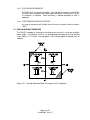
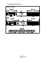
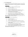
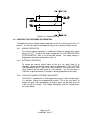
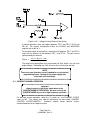
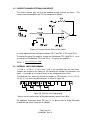
INSTRUCTION MANUAL FOR
83-469-001 Revision B
MODEL
SERIAL NUMBER
LAMBDA EMI
405 ESSEX ROAD, NEPTUNE, NJ 07753
TEL: (732) 922-9300
FAX: (732) 922-9334
TABLE OF CONTENTS
Description
Page
...................................................
1.1 INTRODUCTION . . . . . . . . . . . . . . . . . . . . . . . . . . . . . . . . . . . . . . . . . . . . . . . . . . . . . . . . . . . . . . . .
1.2 SAFETY PRECAUTIONS . . . . . . . . . . . . . . . . . . . . . . . . . . . . . . . . . . . . . . . . . . . . . . . . . . . . . . . . .
1.3 RETURNING EQUIPMENT . . . . . . . . . . . . . . . . . . . . . . . . . . . . . . . . . . . . . . . . . . . . . . . . . . . . . . .
1.4 SPECIFICATIONS . . . . . . . . . . . . . . . . . . . . . . . . . . . . . . . . . . . . . . . . . . . . . . . . . . . . . . . . . . . . . . .
1.4.1 INPUT CURRENT REQUIREMENTS . . . . . . . . . . . . . . . . . . . . . . . . . . . . . . . . . . . . . . . . . . . . .
1.4.2 MAXIMUM POWER REQUIREMENTS . . . . . . . . . . . . . . . . . . . . . . . . . . . . . . . . . . . . . . . . . . .
1.4.3 ENVIRONMENTAL REQUIREMENTS . . . . . . . . . . . . . . . . . . . . . . . . . . . . . . . . . . . . . . . . . . . .
1.4.4 ISOLATION REQUIREMENTS . . . . . . . . . . . . . . . . . . . . . . . . . . . . . . . . . . . . . . . . . . . . . . . . . .
1.4.5 COOLING REQUIREMENTS . . . . . . . . . . . . . . . . . . . . . . . . . . . . . . . . . . . . . . . . . . . . . . . . . . . .
1.4.6 OVERTEMPERATURE PROTECTION . . . . . . . . . . . . . . . . . . . . . . . . . . . . . . . . . . . . . . . . . . .
1.5 FOUR QUADRANT OPERATION . . . . . . . . . . . . . . . . . . . . . . . . . . . . . . . . . . . . . . . . . . . . . . . . . .
1.6 ELECTRONIC PERFORMANCE SPECIFICATIONS . . . . . . . . . . . . . . . . . . . . . . . . . . . . . . . . .
1.7 MECHANICAL SPECIFICATIONS . . . . . . . . . . . . . . . . . . . . . . . . . . . . . . . . . . . . . . . . . . . . . . . . .
1
1
1
1
2
2
2
2
2
3
3
3
4
5
...............................................................
2.1 INITIAL SETUP AND TEST . . . . . . . . . . . . . . . . . . . . . . . . . . . . . . . . . . . . . . . . . . . . . . . . . . . . . . .
2.2 RECONFIGURING THE INPUT LINE VOLTAGE . . . . . . . . . . . . . . . . . . . . . . . . . . . . . . . . . . . .
2.3 VITAL FUNCTIONS TEST . . . . . . . . . . . . . . . . . . . . . . . . . . . . . . . . . . . . . . . . . . . . . . . . . . . . . . . .
6
6
6
6
................................................................... 8
3.1 CONNECTING THE LOAD . . . . . . . . . . . . . . . . . . . . . . . . . . . . . . . . . . . . . . . . . . . . . . . . . . . . . . . . 8
3.2 REMOTE SENSING . . . . . . . . . . . . . . . . . . . . . . . . . . . . . . . . . . . . . . . . . . . . . . . . . . . . . . . . . . . . . . 8
3.3 CONSTANT VOLTAGE MODE OF OPERATION . . . . . . . . . . . . . . . . . . . . . . . . . . . . . . . . . . . . 9
3.3.1 MANUAL OPERATION . . . . . . . . . . . . . . . . . . . . . . . . . . . . . . . . . . . . . . . . . . . . . . . . . . . . . . . . . 9
3.3.2 EXTERNAL OPERATION . . . . . . . . . . . . . . . . . . . . . . . . . . . . . . . . . . . . . . . . . . . . . . . . . . . . . . . 9
3.3.3 VOLTAGE CHANNEL EXTERNAL GAIN SELECT . . . . . . . . . . . . . . . . . . . . . . . . . . . . . . . . . 9
3.4 CURRENT CHANNEL OPERATION . . . . . . . . . . . . . . . . . . . . . . . . . . . . . . . . . . . . . . . . . . . . . . 10
3.5 CURRENT CHANNEL EXTERNAL GAIN SELECT . . . . . . . . . . . . . . . . . . . . . . . . . . . . . . . . . 12
3.6 EXTERNAL LIMIT PROGRAMMING . . . . . . . . . . . . . . . . . . . . . . . . . . . . . . . . . . . . . . . . . . . . . . 12
3.7 VOLTAGE AND CURRENT MONITORS . . . . . . . . . . . . . . . . . . . . . . . . . . . . . . . . . . . . . . . . . . 13
3.8 EXTERNAL INTERLOCK . . . . . . . . . . . . . . . . . . . . . . . . . . . . . . . . . . . . . . . . . . . . . . . . . . . . . . . . 13
..................................................
4.1 GENERAL . . . . . . . . . . . . . . . . . . . . . . . . . . . . . . . . . . . . . . . . . . . . . . . . . . . . . . . . . . . . . . . . . . . . .
4.2 A200 POWER AMPLIFIER BOARD . . . . . . . . . . . . . . . . . . . . . . . . . . . . . . . . . . . . . . . . . . . . . . .
4.3 A100 CONTROL BOARD . . . . . . . . . . . . . . . . . . . . . . . . . . . . . . . . . . . . . . . . . . . . . . . . . . . . . . . .
4.3.1 A100 VOLTAGE CHANNEL SIGNAL FLOW . . . . . . . . . . . . . . . . . . . . . . . . . . . . . . . . . . . . .
4.3.2 A100 CURRENT CHANNEL SIGNAL FLOW . . . . . . . . . . . . . . . . . . . . . . . . . . . . . . . . . . . . .
4.3.3 ±10VDC PRECISION REFERENCE . . . . . . . . . . . . . . . . . . . . . . . . . . . . . . . . . . . . . . . . . . . . .
4.3.4 ACTIVE LIMIT CIRCUITRY . . . . . . . . . . . . . . . . . . . . . . . . . . . . . . . . . . . . . . . . . . . . . . . . . . . .
14
14
14
14
16
16
16
16
...................................
5.1 INTRODUCTION TO THE BOS/S DIGITAL CONTROLLER BOARD . . . . . . . . . . . . . . . . . .
5.2 GENERAL DESCRIPTION . . . . . . . . . . . . . . . . . . . . . . . . . . . . . . . . . . . . . . . . . . . . . . . . . . . . . . .
5.3 ELECTRICAL SPECIFICATIONS . . . . . . . . . . . . . . . . . . . . . . . . . . . . . . . . . . . . . . . . . . . . . . . . .
17
17
17
17
........
6.1 GENERAL . . . . . . . . . . . . . . . . . . . . . . . . . . . . . . . . . . . . . . . . . . . . . . . . . . . . . . . . . . . . . . . . . . . . .
6.2 GPIB AND RS232 INTERFACES . . . . . . . . . . . . . . . . . . . . . . . . . . . . . . . . . . . . . . . . . . . . . . . . .
6.3 SET UP COMMANDS . . . . . . . . . . . . . . . . . . . . . . . . . . . . . . . . . . . . . . . . . . . . . . . . . . . . . . . . . . .
6.4 INQUIRY COMMANDS . . . . . . . . . . . . . . . . . . . . . . . . . . . . . . . . . . . . . . . . . . . . . . . . . . . . . . . . . .
6.5 MEASUREMENT COMMANDS . . . . . . . . . . . . . . . . . . . . . . . . . . . . . . . . . . . . . . . . . . . . . . . . . . .
18
18
18
19
19
20
TABLE OF CONTENTS
Description
Page
6.6 CONTROL CHANNEL PROGRAMMING . . . . . . . . . . . . . . . . . . . . . . . . . . . . . . . . . . . . . . . . . . 20
6.7 LIMIT CHANNELS PROGRAMMING . . . . . . . . . . . . . . . . . . . . . . . . . . . . . . . . . . . . . . . . . . . . . . 21
......................................
7.1 GENERAL . . . . . . . . . . . . . . . . . . . . . . . . . . . . . . . . . . . . . . . . . . . . . . . . . . . . . . . . . . . . . . . . . . . . .
7.2 CALIBRATION . . . . . . . . . . . . . . . . . . . . . . . . . . . . . . . . . . . . . . . . . . . . . . . . . . . . . . . . . . . . . . . . .
7.2.1 THE INTERNAL ±10VDC REFERENCE . . . . . . . . . . . . . . . . . . . . . . . . . . . . . . . . . . . . . . . . .
7.2.2 DIGITAL AND ANALOG METER CALIBRATION . . . . . . . . . . . . . . . . . . . . . . . . . . . . . . . . .
24
24
24
24
24
1 GENERAL INFORMATION
1.1 INTRODUCTION
This manual contains instructions for the operation and maintenance of the BOS/S
100, 200, 400 Watt Bi-polar operational Source/Sink Power Supply series
manufactured by Electronic Measurements, Inc. of Neptune, NJ.
The BOS/S is a Bipolar Operational Source/Sink Amplifier, a true four quadrant power
supply with high bandwidth capabilities. It utilizes the latest MOSFET technology for
high slew rates and high efficiency.
The BOS/S power supplies have been developed for applications where high stability,
accuracy, fast response times and bipolar capabilities are required. It is well suited for
laboratory, test and measurement applications.
The BOS/S has two modes of operation, constant voltage and constant current. The
modes of operation are selected by switch position (Item 6, Dwg. No. 02-469-101).
The BOS/S also provides dynamic limiting of voltages and current regardless of which
mode of operation is selected.
1.2 SAFETY PRECAUTIONS
All EMI power supplies are designed for safe operation. This instrument received
comprehensive mechanical and electrical inspection prior to shipment. Nevertheless,
certain safety precautions must be observed. Only technically competent personnel
familiar with the principles of electrical safety should operate this supply. To prevent
fire or shock hazard, the power supply should not be exposed to water or moisture.
Electrical safety should be maintained at all times.
Lethal voltages are developed within the power supply’s enclosure whenever it is
energized. Therefore, the power supply must always be unplugged prior to removing
the cover. If the input to power supply is hardwired, the circuit breaker must be
secured and the line fuses removed.
Of course, dangers are inherent in high voltage equipment. However, a power supply
with a low voltage is also potentially dangerous considering the amount of energy
(current) the supply is capable of delivering. In addition to the steady state energy
available, power supplies are typically terminated by very large capacitors, which can
deliver huge surge currents capable of vaporizing metallic objects such as
screwdrivers or jewelry. This could result in molten metal being sprayed. Proper care
and judgment must always be observed.
1.3 RETURNING EQUIPMENT
This instrument received comprehensive mechanical and electrical inspection before
shipment. Immediately upon receipt from the carrier, and prior to operation, this
instrument should be visually inspected for any damage that may have been incurred
during shipment.
If such inspection reveals internal or external damage in any way, a claim should be
filed with the carrier. A full report of the damage should be furnished to the claim
agent and forwarded to Electronic Measurements, Inc., noting the model and serial
number of the equipment. EMI will determine the proper course of action and arrange
Page 1 of 24
83-469-001 Rev. B
for repair or replacement. Before returning any equipment to the factory, the following
steps should be taken:
1. Notify Electronic Measurement, Inc., Customer Service Department, at telephone
number (908) 922-9300. Give full description of the difficulty, including the model
and serial number of the unit in question. Upon receipt of this information, EMI will
assign a Return Material Authorization (RMA) and provide shipping instructions.
2. Equipment returned to EMI must be packed in such a manner as to arrive without
incurring any damage. The shipping container must be marked with the RMA
number in legible numbers near the shipping label. Any returned unit must have its
RMA number clearly displayed on the outside of the container in order to be
accepted.
3. For non-warranty repairs, EMI will submit a cost estimate for the customer’s
approval prior to proceeding.
1.4 SPECIFICATIONS
1.4.1
INPUT CURRENT REQUIREMENTS
105 to 125VAC – or – 210 to 250VAC, 47 to 63Hz. the line is protected by a
circuit breaker located on the front panel rated for all input voltages.
1.4.2
MAXIMUM POWER REQUIREMENTS
Model Power
20-20
36-12
50-8
72-6
100-4
200-2
20-10
36-6
50-4
72-3
100-2
20-5
50-2
100-1
Output Power (Max)
400W
432W
400W
432W
400W
400W
200W
216W
200W
216W
200W
100W
100W
100W
Max Input Current
Max Input
NOT TO
EXCEED
NOT TO
EXCEED
9.5A
800W
NOT TO
EXCEED
5A
NOT TO
EXCEED
400W
NOT TO
EXCEED
3A
NOT TO
EXCEED
200W
Table 1.1
1.4.3
ENVIRONMENTAL REQUIREMENTS
OPERATING TEMPERATURE:
STORAGE TEMPERATURE
1.4.4
0 to 50 DEGREES CENTIGRADE
-40 to 85 DEGREES CENTIGRADE
ISOLATION REQUIREMENTS
ISOLATION FROM GROUND:
Page 2 of 24
83-469-001 Rev. B
INPUT/GROUND
1500 VAC
OUTPUT/GROUND 1000 VAC
1.4.5
COOLING REQUIREMENTS
All BOS/S units use forced air cooling. The side and rear panels of the BOS/S
must be clear from objects that could impair circulation, a minimum of 4 inches
of clearance is required. Rack mounting is allowed provided air flow is
adequate.
1.4.6
OVERTEMPERATURE PROTECTION
An internal thermostat will disable the unit when the internal heatsink reaches
195°F.
1.5 FOUR QUADRANT OPERATION
The BOS/S is capable of sourcing and sinking current making it a true four quadrant
power supply. In Quadrants II and IV, the average power dissipation must be derated
as per Figure 1.4.7.1 below. Average power is the average power dissipated over 30
seconds.
Figure 1.5.1 Average Allowable Power Dissipation in All 4 Quadrants
Page 3 of 24
83-469-001 Rev. B
1.6 ELECTRONIC PERFORMANCE SPECIFICATIONS
REGULATION
Voltage
0.005% max.
0.005% max.
0.008
0.01%/c max.
3.00mV
Line Regulation
Load Change (100%)
Time
Temperature Coefficient
Output Ripple
MODEL
100 W
BOS/S
20-5
BOS/S
50-2
BOS/S
100-1
200 W
BOS/S
20-10
BOS/S
36-6
BOS/S
50-4
BOS/S
72-3
BOS/S
100-2
400 W
BOS/S
20-20
BOS/S
36-12
BOS/S
50-8
BOS/S
72-6
BOS/S
100-4
BOS/S
200-2
Max DC
DC Output Range
Eo
Io
Bandwidth*
DC to F<3 dB
Full Power
V
Current
0.005
1.0 mA
0.008
0.03%/c
0.05%
I
Slew Rate @
Maximum Load
V
I
±20V
±50V
±100V
±5
±2
±1
20KHz
20KHz
20KHz
15KHz
15KHz
15KHz
1.6v/µs
4v/µs
7V/µs
.4A/µs
.15A/µs
.08A.µs
±20V
±36V
±50V
±72V
±100V
±10A
± 6A
± 4A
± 3A
± 2A
20KHz
18KHz
18KHz
18KHz
18KHZ
10KHz
15KHz
12KHz
12KHz
12KHz
1.6V/µs
3V/µs
4V/µs
5.8V/µs
6V/µs
.8A/µs
.5A/µs
.3A/µs
.25A/µs
.15A/µs
±20V
±35V
±50V
±72V
±100V
±200V
±20A
±12A
± 8A
± 6A
± 4A
± 2A
10KHz
20KHz
25KHz
20KHz
15KHz
10KHz
12KHz
13KHz
12KHz
12KHz
10KHz
2KHz
1.6V/µs
3V/µs
4V/µs
5.8V/µs
6.0V/µs
4.0V/µs
1.6A/µs
1A/µs
.7A/µs
.5A/µs
.3A/µs
.05A/µs
* Bandwidth specifications apply to purely resistive load impedance. For other application,
contact EM Engineering to discuss possible effects of the load in the power supply.
Page 4 of 24
83-469-001 Rev. B
1.7 MECHANICAL SPECIFICATIONS
Page 5 of 24
83-469-001 Rev. B
2 INSTALLATION
2.1 INITIAL SETUP AND TEST
Before connecting the unit to the powerline, the user should verify the line cord is of the
proper gauge (Refer to para. 1.2.2 for loading requirements) and the safety ground is
connected. The user should verify the unit is configured for the proper input voltage. To
determine the proper configuration check the top of the unit for appropriate marking.
2.2 RECONFIGURING THE INPUT LINE VOLTAGE
To reconfigure the input line voltage the following steps must be performed.
1.
Verify the input power is removed.
2.
Remove the top cover and locate T1.
3.
Use Table I for proper placement of wires.
4.
Refer to figure below for terminal location.
Table 1 – Wire Placement
For 115 VAC OPERATION
LUG #
WIRE COLOR AND GAUGE
FOR 115 VAC OPERATION
1
White #14
1
White #20
1
White #14
1
W/Brown #20
1
Brown #20
3
Black #14
3
Black #20
3
Black #14
3
Black #20
3
W/Black #20
FOR 220 VAC OPERATION
1
White #14
1
White #20
1
Brown #20
2
Black #14
2
White #14
2
W/Brown #20
2
W/Black #20
2
Black #20
3
Black #14
3
Black #20
METRIC SIZE
Page 6 of 24
83-469-001 Rev. B
FROM LOCATION
16
9
16
9
9
16
9
16
9
9
CB1
FAN
T1-2
T2-2
T2-1
CB1
FAN
T1-3
T2-4
T2-3
16
9
9
16
16
9
9
9
16
9
CB1
FAN
T2-1
T1-3
T1-2
T2-2
T2-3
FAN
CB1
T2-4
2.3 VITAL FUNCTIONS TEST
After the appropriate line voltage has been applied to the BOS/S, it may be desirable
to do a VITAL FUNCTIONS TEST to verify that no damage was sustained during
shipment.
VOLTAGE MODE
A)
Ensure that the voltage sensing leads are connected.
B)
Switch the V/I switch to V.
C)
Switch the VOLTAGE INT/EXT to INT.
D)
Rotate the VOLTAGE CONTROL POTENTIOMETER fully clockwise.
E)
Rotate the +V LIM POTENTIOMETER fully clockwise, -V LIM
POTENTIOMETER fully counter clockwise.
F)
Turn unit on by pressing CB1 upward to the ON position.
G)
When unit turns on, the fan will be audible, the V MODE LED will
illuminate and the Voltage Meter should be deflected full scale positive.
Rotate the VOLTAGE CONTROL POTENTIOMETER fully counter clockwise and
observe meter deflection in the negative direction.
CURRENT MODE
A)
Place a short circuit on output terminals.
B)
Switch the V/I switch to I.
C)
Switch the CURRENT INT/EXT to INT.
D)
Rotate the CURRENT CONTROL POTENTIOMETER fully clockwise
E)
Rotate the +I LIM POTENTIOMETER fully clockwise, -I LIM POTENTIOMETER
fully counter clockwise.
F)
Turn unit on by pressing CB1 upward to the ON position.
G)
When the unit turns on, the fan will be audible, I mode LED will illuminate
and the Current Meter should be deflected full scale positive.
Rotate the CURRENT CONTROL POTENTIOMETER counter clockwise and observe
meter deflection in the negative direction.
Page 7 of 24
83-469-001 Rev. B
3 OPERATION
3.1 CONNECTING THE LOAD
The load can be connected to the front or rear panel of the BOS/S. The front panel
connection is a 5 way binding post and the output at the rear panel is located on TB2
labeled Plus (+) and Minus (-). (See Drawing 02-469-001.)
The load must be connected with wires of the appropriate gauge avoiding excessive
lengths and bundling, reducing reactive components. When possible, twist the load
wires to reduce noise from stray fields.
3.2 REMOTE SENSING
The remote voltage sensing of the BOS/S is done at the front panel. If there are long
load wires which are carrying currents, a potential drop occurs in the wires. To
achieve accurate control of the load voltage, remove the sense jumpers at the front
panel and connect sense wires between the load and plus and minus sense at the rear
or front of the power supply.
NOTE 1:
When using remote sensing, always use twisted pair wires of at least 22 AWG.
If possible, use shielded twisted pair to reduce interference.
NOTE 2:
Certain combinations of R & C at the load can resonate and add additional
feedback phase shift which will cause the internal feedback loop to oscillate.
For example, when the load wires are more than 15 feet long the associated
inductance becomes significant. This inductance could resonate with a 10 to
20µF load bypass capacitor and add an additional phase shift of 90 degrees
which would cause an oscillation. Adding 100µF capacitors at the power supply
between + OUT and +SENSE. -OUT and -SENSE will in most cases, stop any
oscillation and still not deteriorate the transient response (See Figure 3.2.1).
Polarized or non-polarized capacitors may be used. If polarized capacitors are
used, proper polarity must be observed (See Figure 3.2.1).
Page 8 of 24
83-469-001 Rev. B
Figure 3.2.1 Remote Sensing
3.3 CONSTANT VOLTAGE MODE OF OPERATION
To enable the constant voltage mode of operation set the V/I switch (Item 6) to the “V”
position. The unit can now be controlled manually or via an external voltage source.
3.3.1
MANUAL OPERATION
The manual mode of operation is enabled by setting the voltage input switch
(Item 8) to “INT”. To adjust the output voltage turn the “VOLTAGE CONTROL
POTENTIOMETER” (Item 9) to the desired voltage. The output voltage is
displayed on the output voltage meter (Item 11).
3.3.2
EXTERNAL OPERATION
To enable the external control inputs of the unit, set switch (Item 8) to
“External”. Attach an external control signal to binding posts “EXT VOLTAGE
PROGRAMMING INPUT” (Item 10) on the front panel. The red terminal is the
signal terminal and the black terminal is the common. The full-scale input is
±10V with respect to common, the output is directly proportional to the input.
3.3.3
VOLTAGE CHANNEL EXTERNAL GAIN SELECT
The BOS/S is supplied with a ±10V programming for full scale voltage output.
It is possible, through the programming terminal, TB1 on the rear panel, to
change the gain of the preamplifier so remote inputs can be lower than the
±10V set from the factory. The Voltage Preamplifier and TB1 configurations
are shown below.
Page 9 of 24
83-469-001 Rev. B
Figure 3.3.3.1 Voltage Channel External Gain Select
In normal operation, there are jumpers between TB1-7 and TB1-8, TB1-9 and
TB1-10. This jumper configuration makes the OP-AMP and INVERTING
amplifier with a gain of -1.
To change the gain of the amplifier, remove the link between TB1-7 and TB1-8
and insert an external resistor between TB1-7 and TB1-8. The gain can be
represented by the formula:
Gain =
External Re sistor +10K
10K
The output of the preamplifier must not exceed ±10 Volts which is the full scale
output voltage. Exceeding the ±10V will cause the limit circuit to activate.
NOTE:
These rear panel terminals are not intended for use as external
programming inputs. Damage to the power supply may
result from such an attempt.
3.4 CURRENT CHANNEL OPERATION
Important:
Always connect a load to the output when in the
CURRENT MODE OF OPERATION. An open circuit in the
CURRENT MODE may result in high frequency oscillation.
For constant current regulation, switch the V/I switch to I. the CURRENT INT/EXT
switch to INT. The current may now be adjusted by the front panel CURRENT
CONTROL POTENTIOMETER.
Clockwise rotation causes positive current,
counterclockwise causes negative current.
Page 10 of 24
83-469-001 Rev. B
Switching the CURRENT INT/EXT to EXT, enables the BOS/S to accept an External
Current Control Signal. The EXT CURRENT SIGNAL is input on the red and black
binding posts labeled “EXT CURRENT PROGRAMMING INPUT” (Item 15, dwg
02-469-101). The control signal is connected to the red binding post, and the common
is connected to the black post. Fullscale programming is ±10V with respect to
common. The output is directly proportional to the input signal.
Rear Panel Detail
1.
SPARE
2.
I GAIN R
3.
I INV IN
See “VOLTAGE CHANNEL EXT
4.
GND
GAIN SELECT” Sec. 3.3.3
5.
I + IN
6.
SPARE
7.
V GAIN R
8.
V INV IN
See CURRENT CHANNEL EXT
9.
GND
GAIN SELECT” Sec 3.5
10.
V + IN
11.
+V LIM IN
12.
+V LIM V
13.
-V LIM IN
14.
-V LIM V
15.
+I LIM IN
16.
+1 LIM V
17.
-I LIM IN
18.
-I LIM V
19.
V MONITOR
20.
I MONITOR
21.
ON/OFF
22.
ON/OFF RTN
23.
SPARE
24.
COMM
Page 11 of 24
83-469-001 Rev. B
3.5 CURRENT CHANNEL EXTERNAL GAIN SELECT
The current channel gain can also be modified through external resistance.
current channel preamplifier and TB1 are configured as follows:
The
Figure 3.5 Current Channel External Gain Select
In normal operation there are jumpers between TB1-2 and TB1-3, TB1-4 and Tb1-5.
To change the gain of the amplifier, remove the link between TB1-2 qnd TB1-3. Insert
an external resistor between TB1-2 and TB1-3. The gain of the amplifier is:
Gain =
External Re sistor +10K
10K
3.6 EXTERNAL LIMIT PROGRAMMING
+ V LIM V, -V LIM V, +I LIM V and -I LIM V are controlled from the front panel.
Jumpers are installed at the factory on TB1 between the voltage limit references and
inputs. It is possible to use external levels for the voltage and current limits.
To change the limits externally, remove the jumpers on TB1 terminals (11-12), (13-14),
(15-16), (17-18) and install potentiometers as shown in Figure 3.6
Figure 3.6 External Limit Programming
* Always use resistance values for the potentiometers greater than 10KΩ
For additional information about TB1 pins 11-18, please refer to A100 Schematic
01-000-234 and overall schematic 01-469-001.
Page 12 of 24
83-469-001 Rev. B
3.7 VOLTAGE AND CURRENT MONITORS
The V monitor and I monitor each have a ±10 Volt fullscale voltage, which is
proportional to the unit’s output.
The voltage monitor is present at TB1-20, using TB1-24 as common.
The current monitor is present at TB1-19 using TB1-24 as common.
3.8 EXTERNAL INTERLOCK
An external interlock function can be achieved by providing a dry normally open (NO)
contact between TB1-21 and TB1-22 which will cause the front panel circuit breaker to
trip.
Page 13 of 24
83-469-001 Rev. B
4 THEORY OF OPERATION
4.1 GENERAL
1. The BOS/S THEORY OF OPERATION shall describe the following major sections.
2. A200 Output Stage
3. A100 Control Board
4. Simplified Schematic, Voltage Channel
5. Simplified Schematic, Current Channel
6. Voltage Channel Signal Flow
7. Current Channel Signal Flow
8. ±10 VDC Precision Reference
9. Active Limit Circuitry
4.2 A200 POWER AMPLIFIER BOARD
The A200 PCB’s function is to provide power amplification of the Current or Voltage
Mode Signals which are provided by the A100 PCB. The power amplifier is a Quasi
Push/Pull Type Amplifier which directly controls all output functions. The number of
A200 PCBs installed in the unit is determined by the maximum output of the unit.
The A200 assembly contains the heatsinks, buffer amp and output power transistors.
The input signal to the A200 PCB is provided by the A100 PCB. The signa; is applied
to two sets of power amplifiers. One set of power amplifiers causes the output to go
positive with respect to the output common. The other set of amplifiers caused the
output to go negative. The local feedback on the assembly determines the magnitude
of the drive signal. See Figure 4.3.1.
4.3 A100 CONTROL BOARD
The A100 Board contains all vital controls for the BOS/S. It contains circuitry for
switching between Voltage and Current Modes, Internal and External Control, Voltage
and Current Limiting, IEEE and RS232 inputs. It also contains the error amplifiers for
both the Voltage and Current Control and all of the associated feedback components.
The signal flow can be seen for both the Voltage and Current Mode from the simplified
schematics in Figures 4.3.1 and 4.3.2.
Page 14 of 24
83-469-001 Rev. B
Figure 4.3.1 A100 Control Board Simplified Schematic Voltage Channel
Figure 4.3.2 A100 Control Board Simplified Schematic Current Channel
Page 15 of 24
83-469-001 Rev. B
4.3.1
A100 VOLTAGE CHANNEL SIGNAL FLOW
The Voltage and Current Modes provide both Internal or External Control. The
chosen signal is fed into the Voltage Preamplifier. The now inverted signal
flows to the error amplifier and compares it against the output voltage. The
error amplifier’s output drives the A200 PCB, providing the proper output
voltage.
4.3.2
A100 CURRENT CHANNEL SIGNAL FLOW
In the Current Mode, the input control signal is selected between Internal and
External. The signal then flows into the Current Preamplifier. From there the
now inverted signal is fed to the error amplifier, and the error amplifier drives
the A200 regulator. When current flows from the load to the shunt, a voltage
potential is produced across the shunt. The shunt voltage is amplified by a
different amplifier and fed back to the summing junction for closed loop control.
4.3.3
±10VDC PRECISION REFERENCE
A precision voltage reference REF-01 with a temperature stability of 10 ppm is
used as the +10VDC reference. The -10VDC reference is produced by
anOP-07 inverting amplifier with a gain of -1.
4.3.4
ACTIVE LIMIT CIRCUITRY
The active voltage and current limits are sensed by amplifiers. A reference
voltage is fed into the amplifiers from the front panel settings and are compared
to the voltage output exceeds the setpoint, the comparator will decrease the
control signal from the output of the error amplifier, thus protecting the power
supply from overvoltage and overcurrent.
Page 16 of 24
83-469-001 Rev. B
5 BOS/S DIGITAL CONTROLLER BOARD
5.1 INTRODUCTION TO THE BOS/S DIGITAL CONTROLLER BOARD
The following contains all instructions for operation of the BOS/S Digital Controller
Board. This board is a factory-installed option for remote computer control of the
BOS/S power supply, manufactured by Electronic Measurements.
5.2 GENERAL DESCRIPTION
The BOS/S Digital Controller Board provides a means to remotely computer control an
Electronic Measurements, Inc. BOS/S Power Supply. This board is factory installed
within the existing BOS/S enclosure. The controller is interfaced via the General
Purpose Interface Bus (GPIB) or the RS232C serial communications link. Either or
both of these interface methods are available and both can be used at the same time,
providing a great degree of user flexibility.
The controller allows remote duplication of all BOS/S front panel controls. Front panel
controls are remotely locked out by the user via the controller card.
5.3 ELECTRICAL SPECIFICATIONS
Operating Temperature:
0 to 50 degrees Centigrade
Storage Temperature:
-40 to 85 degrees Centigrade
Isolation:
IEEE (RS232)/Power Supply 1000VAC
RS232C Input:
8-BIT WORD, 1 Stop BIT, 1 Start BIT
Switch Selectable Baud Rate 150 to 9600 Bd
IEEE-488 Input:
Compliance to IEEE-488 1978
Switch Selectable Address
Control Channel Resolution:
16-BITS
Control Channel Linearity Error:
±1 LSB
Control Channel F.S. Drift Error:
±25 PPM/°C
Control Channel Zero Drift Error:
<10µV/°C
Control Channel Settling Time:
6µS to ½ LSB
Limit Channel (Pos and Neg Resolution): 8-BITS
Limit Channel Linearity Error:
±2 LSB
Limit Channel Drift Error:
±70PPM/°C
Readback Resolution:
12 or 16 BITS
Readback Linearity Error:
¼ LSB
Readback Drift Error:
±2 LSB max. (0 to 70°C)
Readback Conversion Rate:
<32µS
Page 17 of 24
83-469-001 Rev. B
6 OPERATING INSTRUCTIONS FOR THE BOS/S CONTROLLER
6.1 GENERAL
The BOS/S controller is designed to functionally duplicate all of the controls on the
front panel of a BOS/S power Supply. These controls select the control programming
mode (Voltage or Current), control channel programming level, and positive and
negative limit channel programming levels. The only requirement is that the front
panel external programming inputs (Voltage and Current) be open when using the
BOS/S controller. All other controls and switches are internally bypassed by the
controller board.
6.2 GPIB AND RS232 INTERFACES
The BOS/S controller interfaces to a computer using either GPIB or RS232C (or both)
data transfer methods. The controller accepts a command string from either port and
processes that string. If any messages are generated by the command string (eg.
Voltage Readback) the message is placed in an output buffer.
After the command string is processed the contents of the output buffer are
transmitted over the RS232 lines (if not disabled by the rear switches). At any time the
output buffer may be read using the GPIB. All messages are terminated with a
carriage-return and a linefeed character.
The BOS/S controller implements the following GPIB interface functions:
SH1
AH1
T6
L4
DC1
C0
(Source Handshake)
(Acceptor Handshake)
(Talker)
(Listener)
(Device Clear)
(No Controller)
The response of the BOS/S controller to a Clear is to zero the control programming
DAC. The positive and negative limit DAC’s are not changed. If the power supply is in
remote mode there will be no change in supply output. However, unless a new value
is programmed in for the control channel, the power supply will be zeroed upon
returning to remote operation.
The GPIB address and the RS232 baud rate are selected using the 8-position DIP
switch on the rear of the BOS/S. The settings are as follows:
SW1 SW2 SW3 SW4 SW5 SW6 SW7 SW8
X
X
X
AD5 AD4 AD3 AD2 AD1
0
0
0
0
0
1
0
1
0
0
1
1
1
0
0
1
0
1
1
1
0
1
1
1
Page 18 of 24
83-469-001 Rev. B
Function
RS232 Baud Rate
IEEE Address
RS232 Disabled
150 Baud
300 Baud
600 Baud
1200 Baud
2400 Baud
4800 Baud
9600 Baud
The baud rate is user selectable. However the BOS/S controller requires an 8-bit
word, 1 stop, and 1 start bit for proper communications. There is no hardware
handshaking, a properly received character will be echoed back over the RS232 line
assuming that the echo function is enabled. The default is to echo all characters, this
is modified using the SET BACKTALK COMMAND.
SB1 = echo on
SB0 = echo off
6.3 SET UP COMMANDS
There are several commands that may be issued to the BOS/S controller to select
operating conditions.
Each must be followed by CR LF (ASCII 13, ASCII 10).
The set commands are as follows:
“Set Local” = “SL” = local operation (def)
“Set Remote” = “SR” = remote operation
“Set I Control” = “SI” = current control
“Set V Control” = “SV” = voltage control (def)
“Set Backtalk 0” = “SB0” = RS232 echo off
“Set Backtalk 1” = “SB1” = RS232 echo on (def)
“Set Message length 0” = “SM0” = short output
“Set Message length 1” = SM1” - verbose output (def)
These commands may be explicitly spelled out in the command string sent to the
BOS/S controller, but only those letters that are capitalized are actually needed. The
rest are ignored.
e.g. “Set Message 0” is the same as “SM0”
“Set Remote” is the same as “SR”
6.4 INQUIRY COMMANDS
There are several inquiry commands used to check the operating conditions of the
BOS/S. Each commands must have as its first character a question mark (?) or the
letter “I”. Each must be followed by a CR LF (ASCII 13, ASCII 10). Each of these
commands will result in a message being placed in the output buffer. the length of the
returned message is determined by the setting of the BACKTALK bit (see above)
The inquiry commands are as follows:
“? Control” = “?C” = Voltage or current control?
“? Operation” = “?O” = Local or remote operation?
“? Limit +” = “?L+” = +Limit DAC programming value (hex)?
“? Limit –” = “?L–” = –Limit DAC programming value (hex)?
“?M” will put a message in the output buffer of the following form:
“E/M Model BOS/S 20-10-1-D-3-2-PM Serial 90A-1234”
Page 19 of 24
83-469-001 Rev. B
This is the full model number of the BOS/S supply, including its serial number.
“?S” will return the last command string sent to the BOS/S controller. This can be
useful for debugging command sequences or verifying correct command reception.
6.5 MEASUREMENT COMMANDS
The BOS/S controller is capable of measuring the output voltage and output current of
the power supply. The optional A/D converter will provide either 16-bit or 12-bit
resolution. The readback message is returned as a measure of Volts, Amps, or for
fastest operation as simply the hexadecimal output of the A/D converter. The
conversion rate of the A/D is very fast however, and hex readback will usually not be
needed. The length of the returned message is determined by the setting of the
BACKTALK bit (see above).
The measurement commands are as follows:
“Measure V” = “MV” = measure output voltage and return result in Volts format.
“Measure V heX” = MVX” = measure output voltage and return result in hex format.
“Measure I” = “MI” = measure output current and return result in hex format.
“Measure I heX” = MIX” = measure output current and return in hex format.
These commands may be explicitly spelled out in the command string sent to the
BOS/S controller, but only those letters that are capitalized are actually needed. The
rest are ignored.
Assuming a 10 Volt, 20 Amp BOS/S supply at 10 Volts and -20 Amps, the following
messages would be returned using the following commands:
“MV” will put one of the following messages in the output buffer:
“Voltage = +10.000 Volts or “+10.000”
“MVX” will put on of the following messages in the output buffer”
“Voltage = ffff” or “ffff”
“MI” will put one of the following messages in the output buffer:
“Current = -20.000 Amps” or “-20.000”
“MIX” will put on of the following messages in the output buffer:
“Current = 0000” or “0000”
Note the value of the hex string. The A/D operates in an offset binary fashion:
-Full scale =
Zero =
+Full scale =
0000 hex
7fff hex
ffff hex
6.6 CONTROL CHANNEL PROGRAMMING
The control channel is selected using the “SV” or “SI” commands to select either
voltage or current control for the BOS/S. The control channel has a resolution of
16-bits. There are several methods available to program the control channel. These
are:
Page 20 of 24
83-469-001 Rev. B
Programming in Volts or Amps.
Programming as a percentage of full scale.
Programming the DAC directly in hexadecimal.
The control channel programming commands are of the following forms:
Direct programming (Volts or Amps):
“Program Control +10.000” = “PC+10.000” = “PC10” =
Program to +10.000 Volts or Amps
“Program Control -5.432” = “PC-5.432” =
Program to -5.432 Volts or Amps.
“Program Control 0.000” = “PCO” = program to Zero.
Percentage full scale programming (-%99.99 to +%99.99):
“Program Control %50.00” = “PC%50”
“Program Control %99.99” = “PC%99.99” =
Program Control to %99.99 full scale (max scale)
Program Control -%0.25” = “PC-%.25” =
Program Control to negative %0.25 full scale
Hexadecimal programming (0000h to ffffh):
Program Control heX 0000” = “PCX0” =
Program Control DAC to 0000h (-full scale)
Program Control heX 7fff” = “PCX7fff” =
program Control DAC to 7fffh (zero)
“Program Control ffff” = “PCXffff” =
Program Control DAC to ffffh (+full scale)
“Program Control heX 4000” = “PCX4” =
Program Control DAC to 4000h (+half scale)
6.7 LIMIT CHANNELS PROGRAMMING
The positive and negative limit channels are determined by the control channel
selection. If the control channel is the Voltage channel, then the limit channels limit the
Current channel of the BOS/S. If the Current channel is the control channel, the
Voltage channel is limited.
the positive and negative limit channels are independently programmed signals, each
with a resolution of 8-bits. There are two methods of programming the limits, these
are:
Programming as a percentage of full scale.
Programming the DAC directly in hexadecimal.
Percentage full scale programming (00 to %99, 0 to -%99):
“Program Limit +00” = “PL+00” = Program +Limit to zero
Page 21 of 24
83-469-001 Rev. B
“Program Limit +ff” = “PL+ff” = Program +Limit to full scale
“Program Limit -80” = “PL-80” = Program -Limit to half scale
“Program Limit -00” = “PL-00” - Program -Limit to zero
Hexadecimal programming (00h to ffh, 00 to -ffh)
“Program Limit -%99” = “PL-%99” = Program -Limit to full scale
“Program Limit +%50” = “PL+%99” = Program +Limit to half scale
Interval Programming Commands
The BOS/S controller allows the programming of up to 1001 intervals. An interval has
three properties:
1) Control channel programming level.
2) Duration of programming level
3) Pointer to next interval
By “stringing” together a group of intervals a custom waveform can be produced. The
maximum frequency obtainable (2 interval loop, Durations of 0) is about 1300 Hz.
The Control programming levels can vary from -full scale to +full scale.
The Duration is an integer value from 0 to 65535 where each count is equivalent to
1 millisecond. A Duration of 0 indicates that maximum throughput is desired.
The pointer to next interval is an integer between 0 and 1000. When interval
programming is enabled the first interval to be programmed is interval 0. This
technique is similar o that of a “linked list”, where insertion of a new value into an
existing waveform consists of merely using the next available interval and resetting
only two pointers. This provides a greater flexibility than would be realized using a
linear array of values.
Before an interval may be programmed, it must be selected using the “Interval Select”
command. This command takes the form of:
“Interval Select iiii” = “ISiiii” = Select interval iiii, where iiii is an integer 0 to 1000.
If iiii is omitted, the selected interval defaults to 0.
The Interval channel programming level is selected using the same options as normal
control channel programming. Programming level is entered as:
Control in Volts or Amps
Control as a percentage of full scale
Control the DAC directly in hexadecimal.
The syntax is:
“Interval Control 5” = IC5” = Selected interval control level = 5 Volts or Amps
“Interval Control -%50.12” = IC-%50.12” =
Selected interval control level = -%50.12 full scale
“Interval Control heX ffff” = “ICXffff” =
Selected interval control level of DAC is ffff hex.
The Duration is selected using the following syntax:
Page 22 of 24
83-469-001 Rev. B
“Interval Duration iiii” = “IDiiii” = Set Interval pointer to point at interval iiii, where
iiii is an integer from 0 to 65535. If iiii is omitted, the default duration is 0.
The Pointer is selected using the following syntax:
“Interval Pointer iiii” = “IPiiii” =
Set Interval pointer to point at interval iiii, where iiii is an integer from 0 to
1000.
“Program Interval” = “PI” =
Begin interval programming. This will begin programming the supply using
the values preloaded into the interval programming registers. The first
interval to be programmed is always zero (0). It is essential that the
correct operating modes (REMOTE, V, or I control) are preset, as the
interval will program the control channel regardless of the BOS/S operating
mode.
“? Model” = ?M = Place Model and Serial number in output buffer.
“? Program channel” = “?P” = Control DAC programming value (hex)
“? String” - “?S” = Previous command string
“? Interval iiii” = “?I iiii” = Interval iiii settings?
iiii = 0 to 1000
If iiii omitted then iiii = presently selected interval
These commands may be explicitly spelled out in the command string sent to the
BOS/S controller, but only those letters that are capitalized are actually needed. The
rest are ignored.
“?C” will put one of the following messages in the output buffer:
“V Control” or “V”
“I Control” or “I”
“?O” will put one of the following messages in the output buffer:
“L operation” or “L”
“R operation” or “R”
“?L+” will put one of the following messages in the output buffer”
“+Limit = xx”
“?L-” will put one of the following messages in the output buffer”
“-Limit = xx”
“?P” will put one of the following messages in the output buffer”
“Control = xxxx”
In the previous three examples “xx” and “xxxx” indicate hexadecimal values of 00 to ff
and 0000 to ffff respectively.
Page 23 of 24
83-469-001 Rev. B
7 MAINTENANCE AND CALIBRATION
7.1 GENERAL
A regularly scheduled preventive maintenance schedule is recommended for the
BOS/S series of power supplies. This should consist of wiping the wrapper to prevent
dust build up in the air vents and the cabinet which the BOS/S is installed.
7.2 CALIBRATION
The BOS/S power supplies are fully calibrated at the factory and do not normally
require recalibration.
The following are the only calibrations that may be performed in the field. If other
calibration is required, please contact Electronic Measurements’ Customer Service
Department.
Equipment needed for calibration: Digital Voltmeter, at least 4-½ digits. Shorting bar
for the output terminals.
7.2.1
THE INTERNAL ±10VDC REFERENCE
Set the DVM on the volt scale. Connect the ground lead to TP1, connect the
plus lead to TP2 on the A100 Control Board. Adjust R38 until the DVM is
+10.000VDC. Allow up to 5mV for error. Connect the positive lead to TP3 and
adjust R39 until DVM reading is -10.000. Again, allow up to 5mV for error.
7.2.2
DIGITAL AND ANALOG METER CALIBRATION
The analog meters should be exactly zero centered when the power supply is
off. If the meters are not zero centered, an adjustment on the meters’ front
face should be made. Simply rotate the adjustment screw direction until the
meter shows zero volts or zero amps. Digital meters require no zero
adjustment.
7.2.2.1 Voltmeter
Once the METER ZERO CALIBRATION and the internal ±10VDC
reference has been calibrated, the meters on the front panel can be
calibrated.
With the BOS/S in an open circuit, VOLTAGE MODE and INTERNAL
control, turn the VOLTAGE CONTROL POTENTIOMETER on the
fornt panel fully clockwise. Measure voltage at the output to verify full
scale voltage is obtained. Adjust R44 on the A100 PCB until correct
reading on voltmeter is obtained.
7.2.2.2 Ammeter
With BOS/S in a short circuit, CURRENT MODE and INTERNAL
control, turn the CURRENT CONTROL potentiometer on the front
panel fully clockwise. Adjust R80 until correct full-scale reading on
ammeter is obtained.
Page 24 of 24
83-469-001 Rev. B