1
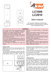
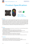
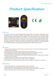
LED CONTROLLER TOUCH RGB
LC 1970
USER'S MANUAL
SAFE USAGE OF THE PRODUCT
This instruction manual contains important information about the installation and use of the projector. Please
read and follow these instructions carefully.
Disconnect the unit from AC power before attempting any operation in contact or inside the unit, and when
not in use.
Refer strictly to this user's manual for the connection to the mains power.
Due to the high technological level of this unit, any service maintenance should be performed by specialised
operators. Please contact your Arena Luci dealer for any operation.
It is essential that each controller is correctly earthed and that electrical installation conforms to all relevant
standards. Never supply the controller without the earth link.
The mains cable should never touch any other cables.
Do not attempt to dismantle and modify the controller.
Do not allow contact with water or any other fluids, or metallic objects (IP 20).
Do not install the projector in areas of high humidity. The unit is intended only for indoor purposes.
Not allowed to be mounted directly on inflammable surfaces.
Always ensure that the structure to which you are attaching the unit is secure and is able to support the
weight of each controller.
The installation of LED modules (including power supplies) should be done according to current technical
rules and regulations. The installation should be performed only by a qualified operator.
Avoid contact with corrosive agents like humidity and moisture on delicate elements: damages from
corrosion are not refunded as component defects.
1/8
TRANSPORT AND SHIPPING
Following carefully the instructions for use explained in this manual you will get the best product
performances for years.
Open the shipping carton and verify that all equipment necessary to operate the system has arrived intact.
Refer to the following packing list for information on what items are included with your model. If any
equipment is missing or damaged, contact your Arena Luci dealer immediately.
Packing list:
1 controller LED TOUCH
1 remote controller
1 instruction manual
Before beginning initial setup of your LED controller, make sure that there is no evident damage caused by
transportation. In the event that the unit’s housing or cable is damaged, do not plug it in and do not attempt
to use it until after contacting your Arena Luci dealer for assistance.
INSTALLING THE INTERFACE
the LED controller TOUCH is an universal high performance RGB that uses the most advanced control
technology. It's based on a microcontroller with PWM functionality, which allows a very fine light intensity
modulation without flicker. The control unit was designed to drive 4-wires low-voltage RGB LED lighting
devices, like RGB modules, LED strips, wall washers, floodlight, underwater RGB LED lamps and other light
sources. The wires are generally labelled R, G, B, + (common supply). Pay attention to connect each control
line to the relevant connector.
Lift the end side cover up to access the connection terminals and connect the RGB devices to the proper
interface outputs, following the instructions provided with the device.
Each output line of this interface offers a screw terminal to which connect the channels red-green-bluecommon of the lighting device.
Follow the power limits at the interface outputs, as explained in the next section.
POWER SUPPLY - MAINS
connect the power supply unit to the mains outlet, paying
attention the output voltage is compatible with the
electrical specifications of the LED controller. Connect the
output lines to the interface terminals labelled “DC +” and
“DC -”, paying attention not to exchange the two terminals:
a wrong polarity may damage the controller.
The LED controller needs a continuous supply voltage of
12V or 24V. You can either use Arena Luci power supplies
or third party ones. The power supply units must be
chosen so that their output power is suitable for the power
needed by the driven devices. The control unit can
automatically recognise if the DC voltage applied to its
terminals is 12V or 24V; this means that it is compatible
with both 12V and 24V powered LED devices, which
represent almost all the products available in the market.
The R-G-B output can drive a maximum load of 6A per
channel and globally the interface can supply a maximum
power output of 216W at 12V and 432W at 24V.
2/8
Be sure that the connected devices don't exceed the 6A per channel power capability. Overloads may
damage the unit. Check the maximum input current of the lighting devices before connect them to the
interface and turn the power on.
This control unit uses the constant voltage driving technique, so its working voltage is the same supplied to
the load. For this reason it is necessary to accurate choose the supply voltage accordingly the connected
devices: for example, if the RGB devices work with DC 12V, you have to supply the interface with a DC 12V
power supply unit, while if the RGB devices work with DC 24V, you have to supply the interface with a DC
24V power supply unit.
It is recommended that the power supply unit is supplied separately so that it may be individually switched on
and off.
Position then the interface in a safe place. Always ensure that the structure and the fixing materials (screws,
hooks, etc.) are secure and able to support the weight of each unit.
Don't install this interface in places that may be easily reached by people who ignore this instruction manual
for use and safety.
OPERATING INSTRUCTIONS
The control unit offers by default 16 colour combinations. The 8 selection buttons on the top side of the body
have a touch sensitive interface, resulting in an easier scene handling. Don't press the buttons strongly.
The 8 buttons are labelled in this way:
“POWER” – “PAUSE” – “MODE +” – “MODE -” – “SPEED +” – “SPEED -” – “BRT +” – “BRT -”.
In the following table you can find the meaning of the buttons of both LED interface and remote controller.
IMAGE
BUTTON
DESCRIPTION
POWER
Turns on and off the controller. When the controller is turned on it
plays the last scene that was running.
PAUSE
Pressing this button stops the execution of the currently selected
scene. Press this button again to continue the execution.
MODE +
Each touch on this button advances to the next automatic scene.
MODE -
Each touch on this button advances to the previous automatic scene.
SPEED +
Adjusts the speed of the current scene, each touch increases the
level.
SPEED -
Adjusts the speed of the current scene, each touch decreases the
level.
BRT +
Adjusts the light intensity, each touch increases the level.
BRT -
Adjusts the light intensity, each touch decreases the level.
OPERATING MODES
The interface provides 16 internal colour changes modes, that is you can automatically run the scenes
stored in the internal memory of the unit. During the fixed colour modes it is possible to adjust the light
intensity. The “pause” function during the execution of colour changing modes or during colour fades allows
to stop the RGB outputs on a fixed combination; moreover the execution speed of dynamic scenes is
adjustable. In the following table you can find the automatic colour changes functions.
3/8
Mode
Function
Description
1
Red
Fixed red, intensity regulation
2
Green
Fixed green, intensity regulation
3
Blue
Fixed blue, intensity regulation
4
Yellow
Fixed yellow, intensity regulation
5
Magenta
Fixed magenta, intensity regulation
6
Cyan
Fixed cyan, intensity regulation
7
White
Fixed white, intensity regulation
8
Colour rotation
Continuous colour change R-G-B-Y-C-M-W, speed regulation
9
Strobe Red
Strobe red, speed regulation
10
Strobe Green
Strobe green, speed regulation
11
Strobe Blue
Strobe blue, speed regulation
12
Strobe Yellow
Strobe yellow, speed regulation
13
Strobe Magenta
Strobe magenta, speed regulation
14
Strobe Cyan
Strobe cyan, speed regulation
15
Strobe White
Strobe white, speed regulation
16
Colour fading
Continuous colour fading R-Y-G-C-B-M, speed regulation
Modes from 1 to 7 allow to control single colours for static illumination. In these seven modes it's not possible
to set the speed.
Modes from 8 to 16 allow to select scenes with colour changes or strobes. It's possible to adjust the speed
but not the light intensity.
Press the button “MODE +” or “MODE -” (or the corresponding buttons on the remote controller) to select
one of the pre-programmed scenes from number 1 to number 16.
REMOTE CONTROLLER
LED TOUCH is shipped with an RF remote controller which can control the colour, the
scene, the speed and light intensity.
The eight buttons on the remote have the same function of the eight buttons on the
body of the interface: “POWER”, “PAUSE” to turn on and off the interface and to
pause it; “MODE +”, “MODE -” to select the operating mode; “SPEED +”, “SPEED -”
to adjust the speed; “BRT +”, “BRT -” to adjust the intensity.
To be able to use the remote controller you have to follow the activation procedure
listed below. If not, LED TOUCH will not recognise the control signals sent via radio.
Turn off the control unit. Press the POWER button on the control unit to turn it on and
then press the POWER button again to turn off the unit. Now press the PAUSE button
on the control unit. The RGB output holds on the red colour, indicating that the
interface is ready to receive a radio control signal. Press the POWER key on the
remote controller you want to associate to the interface. The RGB output flashes in
green indicating the right association between the interface and the remote controller.
Then the output switches off. If the output doesn't flash, just try again the procedure.
Once you have assigned the remote controller, you can run scenes both with LED
TOUCH and remote controller.
OPTIONAL REMOTE CONTROLLER - cod. LC1971
An optional remote controller is available as accessory, which also allows to adjust the colour of emitted light,
as well as controlling the operating mode, the speed and the intensity. All the control panel of this remote is
based on touch sensitive technology, especially useful in live events; there are no mechanical parts, to
guarantee a longer duration of the device.
The six function keys correspond to the six buttons on the interface body: “MODE +”, “MODE -” to select the
programmed effect; “SPEED +”, “SPEED -” to adjust the speed; “BRT +”, “BRT -” to adjust the light intensity.
4/8
The remote controller allows to select more than 60 colour
tonalities, that are showed on the selection wheel and displayed
in the indicating light at the centre of the wheel. For a longer
battery life, there is a 60-seconds auto switch-off timeout that
turns the remote controller off when it is not in use for more
than 60 seconds. Press the switch-on key to turn the remote on
and use it again. It is also possible to control many LED
TOUCH controllers with only one remote controller, by using the
group control mode.
Use the touch sensitive selecting wheel by dragging one finger
on the colour wheel and choose among the 64 available sectors
of different colour. Each sector represents the colour projected
by the LED device; to be precise, the right operating way
consists in drag the finger on the wheel in clockwise direction.
RECHARGING
Connect the USB socket on the remote with the
USB outlet of the computer or other recharging
devices that can supply the recharging voltage of
5V. The remote controller comes with a wall
mounted stand for a better comfort.
The red indicator on the left will be on during the
battery recharging phase, while it will be off at full
charge. During the first four recharging cycles of a
new battery, it is recommended to keep in charge
the remote controller for at least 8-10 hours.
ASSOCIATING THE ADDRESS OF THE REMOTE CONTROLLER LC1971 AND THE LED TOUCH
To be able to control the LED interface with the remote controller it is necessary to define the same address
on both the devices. The address is a numerical code assigned to each LED controller that allows them to
only “listen” to the digital radio control signals sent to one particular controller and discard the signals sent to
the other controllers. The default remote controller shipped with the LED TOUCH will be still operating
properly even after you assign the optional LC1971. The procedure to associate the address is the following.
1.a - turn on the remote controller by pressing the switch on key on the bottom right.
1.b - press the keys from 1 to 9 followed by the “#” key to assign a new address to the remote controller (for
example, the combination “1 #” assigns the address 1 to the remote, while the combination “1 3 #” assigns
the address 13). The same value must be assigned to the LED TOUCH interface.
2.a - after connecting the LED devices to the interface, supply the interface and then press the POWER
button on the interface to turn off the unit and the LED.
2.b - press the PAUSE button on the interface. The RGB output holds on the red colour, indicating that the
interface is ready to receive a radio control signal.
2.c - press the numerical keys on the remote controller to assign the receiver the same address set in step 1.
2.d - press the POWER key on the remote controller you want to associate to the led touch. The RGB output
flashes in green indicating the right address association between the interface and the remote controller. If
the output doesn't flash, just try again the procedure.
There is also the “group control” functionality, that is only one remote controller can handle many LED
drivers. In the following example it is shown how this functionality can be useful in controlling four receivers
A, B, C, D with only one remote controller.
First of all, assign an unambiguous address to the four receivers, each time changing the address with the
numerical keys on the remote and sending it to the single interface as described in step 2; for example, you
can assign address 1 to the receiver A, address 2 to the receiver B, 3 to C and 4 to D, but it is also possible
to specify two-digits addresses. It's necessary to keep in mind or write down the values of addresses,
otherwise if you forget anyone you will have to repeat all the assignment procedure.
Once finished the address assignment you can simply control all the receivers by changing the address on
the remote controller every time you need to control a new interface. By pressing the “1” key followed by the
“#” key on the remote controller you activate the connection with receiver A (which had address 1 previously
5/8
assigned). By pressing the “2” key followed by the “#” key on the remote controller you activate the
connection with receiver B and so on in the same way for receivers C and D. The operation to change the
address on the remote controller is necessary each time you want to control a different RGB controller. The
remote controller stores the last address set when it is switched off.
LINE AMPLIFIER
When the number of LED devices to drive exceeds the driving capability of a single LED TOUCH interface,
or if the distance to cover is too long, the signals emitted by the interface may become corrupted thus
generating malfunctions in the devices. It is then necessary to use a line amplifier (or repeater, cod. LC2036)
that restores the original level of the control signal. Such an amplifier should be placed between the LED
TOUCH outputs and the lighting devices, even if the outputs directly drive an LED source. Connect the R-GB-V outputs of the controller to the relevant R-G-B-V inputs of the amplifier; the LED devices are connected
to the R-G-B-V outputs of the amplifier. It is possible to connect many amplifiers in parallel, as depicted in
the following example, to build virtually unlimited chains of RGB devices. Each amplifier must be supplied by
a dedicated power adapter; connect the power supply outputs to the amplifier input terminals labelled “+” and
“-”, paying attention not to exchange the two wires. Power adapters should be chosen so that the power
supplied to the load is adequate to the power needed by the driven devices.
6/8
TECHNICAL SPECIFICATIONS
POWER SUPPLY:
12V / 24V DC
POWER CONSUMPTION:
216W at 12V - 432W at 24V
OUTPUT CURRENT:
6A each channel
OUTPUT CHANNELS:
3
FUNCTIONS:
16 operating modes in memory.
Adjustable switching speed and light intensity for dynamic effects.
OPTIONAL REMOTE
CONTROLLER LC1971:
Battery capacity: 800mAh
Standby current: <50uA
Battery life in standby: 1 year
Battery life in normal use: 30 days
Charging time: 4 hours
Charging cycles: 500 times
PROTECTION RATING:
IP 20
OPERATING CONDITIONS:
Working temperature from -35°C to +55°C
DIMENSIONS:
Control unit: 226mm L x 45mm W x 29mm H
Remote controller: 79mm L x 40mm W x 6mm H
Remote controller LC1971: 148mm L x 58mm W x 17mm H
WEIGHT:
Control unit: 150g
Remote controller: 22g
Remote controller LC1971: 100g
REFERENCE NORM:
Directive EMC 89/336/EEC, 93/68/EEC, BT73/23/EEC.
Norm EN 50419
Directive 2002/96/EC
TROUBLESHOOTING
In the following table some of the most frequent problems and their possible solutions are listed.
Problem
Possible solution
The interface doesn't work
The interface isn't properly supplied:
- check the power cable is connected
- verify the right polarity of electrical connection
- check the power supply is on and it is working and that the thermal protection
didn't switch off the supply
- test the output voltage of the power supply and verify it is suitable to drive the
LED devices connected
- check the integrity of power cables
The LED devices don't switch - check the supply voltage is suitable to drive the connected device
on
- check the power needed by the device is not greater than the power
available from the supply and the interface
- check the signal lines are properly connected to the output lines of the
interface
- check the integrity of power cables
Wrong colours
- wrong R-G-B connection of the output lines: connect again the output lines
and the relevant inputs
- the line amplifier could be connected with exchanged wires: connect again
the inputs of the amplifier to the relevant output lines
The buttons don't respond
The PAUSE button has been selected: press the PAUSE button again to exit
No scene change in some
The execution speed could be too slow: press the “speed +” button to
operating modes
accelerate
Different light intensity from
- the output cable is too long: reduce the length or use regeneration circuits
the beginning to end of the
- the output cable section is too small: use a cable with a larger cross section
line.
- overload over the capability of the controller: change the power supply unit
or use a line amplifier
7/8
Problem
The remote controller
doesn't work
Possible solution
- the battery is over: change the battery of the series remote controller
(standard 3V button type CR2032)
- for the mod. LC 1971: if the battery is over, recharge as explained above in
the manual
- distance greater than the coverage range of the remote: reduce the distance
from the interface
WARRANTY CONDITIONS
The guarantee is valid for 12 (twelve) months starting from the delivery date of the products and covers
defects of constructions, manufacture or material in the device.
The guarantee does not respond for damages occurred to the units during transport and for irrational use
and
inaccuracy in regular maintenance of the product.
The guarantee decays anyway in case the product has been modified or opened from unauthorized person.
The guarantee does not include the substitution of the product.
The serial number and the product model are necessary to get informations or assistance from the dealer.
CE NORMS
This device complies with directives EMC 89/336/EEC, 93/68/EEC, BT73/23/EEC.
The device complies with norm EN 50419 on the restriction of the use of certain hazardous substances in
electrical and electronic equipment (RoHS) and complies with directive 2002/96/EC on Waste Electrical and
Electronic Equipment (WEEE).
Attention
The European Directive 2002/96/EC on Waste Electrical and Electronic Equipment (WEEE), requires that old
lighting fixtures must not be disposed in the normal unsorted municipal waste stream. Old appliances must
be collected separately in order to optimise the recovery and recycling of the materials they contain and
reduce the impact on human health and the environment.
The crossed out “wheeled bin” symbol on the product reminds that when you dispose the appliance it must
be separately collected.
Consumers should contact their local authority or retailer for information concerning the correct disposal of
their old appliance.
Please note that as part of Arena Luci's ongoing commitment to continuous product development, specifications are subject to change without
notice. Whilst every care is taken in the preparation of this manual Arena Luci reserves the right to change specifications in the course of product
improvement. The publishers cannot be held responsible for the accuracy of the information herein, or any consequence arising from them.
8/8