1
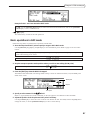
WARNING
To prevent fire or shock hazard, do not
expose this appliance to rain or moisture.
Operator’s Manual
WARNING!!
To prevent fire or shock hazard, do not expose this appliance to rain or moisture.
1-En
CAUTION
RISK OF ELECTRIC SHOCK
DO NOT OPEN
CAUTION: TO REDUCE THE RISK OF ELECTRIC SHOCK,
DO NOT REMOVE COVER (OR BACK).
NO USER-SERVICEABLE PARTS INSIDE.
REFER SERVICING TO QUALIFIED SERVICE PERSONNEL.
THE SYMBOLS ARE RULED BY UL STANDARDS (U.S.A.)
The lightning flash with arrowhead symbol , within an equilateral triangle, is intended to
alert the user to the presence of uninsulated “dangerous voltage” within the product’s
enclosure; that may be of sufficient magnitude to constitute a risk of electric shock to
persons.
The exclamation point within an equilateral triangle is intented to alert the user to the
presence of important operating and maintenance (servicing) instructions in the literature
accompanying the appliance.
5B-En
Rev.2 1/09/98
WARNING
WARNING
The DPS12 is designed to be used in a standard household environment.
Power requirements for electrical equipment vary from area to area. Please ensure that your DPS12 meets
the power requirements in your area. If in doubt, consult a qualified electrician or Akai Professional dealer.
120 VAC
220~240 VAC
@ 60 Hz for USA and Canada
@ 50 Hz for Europe
PROTECTING YOURSELF AND THE DPS12
•
Never touch the AC plug with wet hands.
•
Always disconnect the DPS12 from the power supply by pulling on the plug, not the cord.
•
Allow only an Akai Professional dealer or qualified professional engineer to repair or reassemble the DPS12.
Apart from voiding the warranty, unauthorized engineers might touch live internal parts and receive a serious
electrical shock.
•
Do not put, or allow anyone to put any object, especially metal objects, into the DPS12.
•
Use only a household AC power supply. Never use a DC power supply.
•
If water or any other liquid is spilled into or onto the DPS12, disconnect the power, and call your dealer.
•
Make sure that the unit is well-ventilated, and away from direct sunlight.
•
To avoid damage to internal circuitry, as well as the external finish, keep the DPS12 away from sources of
direct heat (stoves, radiators, etc.).
•
Avoid using aerosol insecticides, etc. near the DPS12. They may damage the surface, and may ignite.
•
Do not use denaturated alcohol, thinner or similar chemicals to clean the DPS12. They will damage the
finish.
•
Modification of this equipment is dangerous, and can result in the functions of the DPS12 being impaired.
Never attempt to modify the equipment in any way.
•
Make sure that the DPS12 is always well-supported when in use (either in a specially-designed equipment
rack, or a firm level surface).
•
In order to assure optimum performance of your DPS12, select the setup location carefully, and make sure
the equipment is used properly. Avoid setting up the DPS12 in the following locations:
1.
2.
3.
4.
5.
In a humid or dusty environment
In a room with poor ventilation
On a surface which is not horizontal
Inside a vehicle such as a car, where it will be subject to vibration
In an extremely hot or cold environment
i
WARNING
WARNING
THIS APPARATUS MUST BE EARTHED
IMPORTANT
This equipment is fitted with an approved non-rewireable UK mains plug.
To change the fuse in this type of plug proceed as follows:
1) Remove the fuse cover and old fuse.
2) Fit a new fuse which should be a BS1362 5 Amp A.S.T.A or BSI approved type.
3) Refit the fuse cover.
If the AC mains plug fitted to the lead supplied with this equipment is not suitable for your type of AC outlet
sockets, it should be changed to an AC mains lead, complete with moulded plug, to the appropriate type.
If this is not possible, the plug should be cut off and a correct one fitted to suit the AC outlet. This should
be fused at 5 Amps.
If a plug without a fuse is used, the fuse at the distribution board should NOT BE GREATER than 5 Amp.
PLEASE NOTE:
THE SEVERED PLUG MUST BE DESTROYED TO AVOID A POSSIBLE
SHOCK HAZARD SHOULD IT BE INSERTED INTO A 13 AMP SOCKET
ELSEWHERE.
The wires in this mains lead are coloured in accordance with the following code:
GREEN and YELLOW —EARTH
BLUE
—NEUTRAL
BROWN
—LIVE
As the colours of the wires in the mains lead of this apparatus may not correspond with the coloured
markings identifying the terminals in your plug, please proceed as follows:
The wire which is coloured GREEN and YELLOW must be connected to the terminal which is marked
with the letter E or with the safety earth symbol or coloured GREEN or coloured GREEN and
YELLOW.
The wire which is coloured BLUE must be connected to the terminal which is marked with the letter
N or coloured BLACK.
The wire which is coloured BROWN must be connected to the terminal which is marked with the letter
L or coloured RED.
THIS APPARATUS MUST BE EARTHED
Ensure that all the terminals are securely tightened and no loose strands of wire exist.
Before replacing the plug cover, make certain the cord grip is clamped over the outer sheath of the lead
and not simply over the wires.
6D-En
ii
WARNING
VENTILATION
Do not prevent the unit's ventilation, especially by placing the unit on the soft carpet, in a narrow space,
or by placing objects on the unit's chassis—top, side, or rear panels. Always keep the unit's chassis at least
10 centimeters from any other objects.
31C-En
CHANGES OR MODIFICATIONS NOT EXPRESSLY APPROVED BY THE MANUFACTURER FOR
COMPLIANCE COULD VOID THE USER’S AUTHORITY TO OPERATE THE EQUIPMENT.
32-En
FCC WARNING
This equipment has been tested and found to comply with the limits for a Class B digital device pursuant
to Part 15 of the FCC rules. These limits are designed to provide reasonable protection against harmful
interference in a residential installation. This equipment generates, uses, and can radiate radio frequency
energy and, if not installed and used in accordance with the instructions, may cause harmful interference
to radio communications. However, there is no guarantee that interference will not occur in a particular
installation. If this equipment does cause harmful interference to radio or television reception, which can
be determined by turning the equipment off and on, the user is encouraged to try to correct the interference
by one or more of the following measures:
•
•
•
•
Reorient or relocate the receiving antenna.
Increase the separation between the equipment and receiver.
Connect the equipment into an outlet on a circuit different from that to which the receiver is connected.
Consult the dealer or an experienced radio/TV technician for help.
21B-En
This digital apparatus does not exceed the Class B limits for radio noise emissions from digital apparatus
set out in the Radio Interference Regulations of the Canadian Department of Communications.
27-En
COPYRIGHT NOTICE
The AKAI DPS12 is a computer-based device, and as such contains and uses software in DISKs and ROMs.
This software, and all related documentation, including this Operator’s Manual, contain proprietary information
which is protected by copyright laws. All rights are reserved. No part of the software or its documentation may
be copied, transferred or modified. You may not modify, adapt, translate, lease, distribute, resell for profit or
create derivative works based on the software and its related documentation or any part there of without prior
written consent from AKAI Electric Co. Ltd, Yokohama, Japan.
iii
WARNING
WARRANTY
AKAI Electric Co. Ltd. warrants its products, when purchased from an authorized “AKAI professional” dealer,
to be free from defects in materials and workmanship for a period of 12 (twelve) months from the date of
purchase. Warranty service is effective and available to the original purchase only, and only on completion and
return of the AKAI Warranty Registration Card within 14 days of purchase.
Warranty coverage is valid for factory-authorized updates to AKAI instruments and their software, when their
installation is performed by an authorized AKAI Service Center, and a properly completed Warranty
Registration has been returned to your “AKAI professional” dealer.
To obtain service under this warranty, the product must, on discovery of the detect, be properly packed and
shipped to the nearest AKAI Service Center. The party requesting warranty service must provide proof of
original ownership and date of purchase of the product.
If the warranty is valid, AKAI will, without charge for parts or labor, either repair or replace the defective part(s).
Without a valid warranty, the entire cost of the repair (parts and labor) is the responsibility of the product's owner.
AKAI warrants that it will make all necessary adjustments, repairs and replacements at no cost to the original
owner within 12 (twelve) months of the purchase date if:
1) The product fails to perform its specified functions due to failure of one or more of its components.
2) The product fails to perform its specified functions due to defects in workmanship.
3) The product has been maintained and operated by the owner in strict accordance with the written
instructions for proper maintenance and use as specified in this Operator's Manual.
Before purchase and use, owners should determine the suitability of the product for their intended use, and
owner assumes all risk and liability whatsoever in connection therewith. AKAI shall not be liable for any injury,
loss or damage, direct or consequential, arising out of use, or inability to use the product.
The warranty provides only those benefits specified, and does not cover defects or repairs needed as a result
of acts beyond the control of AKAI, including but not limited to:
1) Damage caused by abuse, accident, negligence. AKAI will not cover under warranty any original factory
disk damaged or destroyed as a result of the owner's mishandling.
2) Damage caused by any tampering, alteration or modification of the product: operating software, mechanical
or electronic components.
3) Damage caused by failure to maintain and operate the product in strict accordance with the written
instructions for proper maintenance and use as specified in this Operator's Manual.
4) Damage caused by repairs or attempted repairs by unauthorized persons.
5) Damage caused by fire, smoke, falling objects, water or other liquids, or natural events such as rain, floods,
earthquakes, lightning, tornadoes, storms, etc.
6) Damage caused by operation on improper voltages.
IMPORTANT NOTE: This warranty becomes void if the product or its software is electronically
modified, altered or tampered with in any way.
AKAI shall not be liable for costs involved in packing or preparing the product for shipping, with regard to time,
labor, or materials, shipping or freight costs, or time or expense involved in transporting the product to and from
AKAI Authorized Service Center or Authorized Dealer.
AKAI will not cover under warranty an apparent malfunction that is determined to be user error, or owner's
inability to use the product.
THE DURATION OF ANY OTHER WARRANTIES, WHETHER IMPLIED OR EXPRESS, INCLUDING BUT
NOT LIMITED TO THE IMPLIED CONDITION OF MERCHANTABILITY, IS LIMITED TO THE DURATION OF
THE EXPRESS WARRANTY HEREIN.
AKAI hereby excludes incidental or consequential damages, including but not limited to:
1)
2)
3)
4)
5)
6)
iv
Loss of time.
Inconvenience
Delay in performance of the Warranty.
The loss of use of the product.
Commercial loss.
Breach of any express or implied warranty, including the Implied Warranty of Merchantability, applicable to
this product.
Table of contents
Table of contents
Chapter 1: Outline of the DPS12 ............................................. 1
Features of the DPS12 ...................................................................................................... 1
Parts and functions ........................................................................................................... 2
Top panel .................................................................................................................. 2
Front panel ............................................................................................................... 5
Rear panel ................................................................................................................ 5
Using an optional JAZ drive ............................................................................................. 6
Inserting and ejecting a JAZ disk ............................................................................... 6
Notes on using an optional JAZ drive ........................................................................ 7
About external SCSI devices ............................................................................................. 8
Connecting an external SCSI device .......................................................................... 8
About Projects ............................................................................................................... 10
About physical tracks and virtual tracks .......................................................................... 10
TRACK MIX channels and THRU MIX channels .............................................................. 11
About a scene memory .................................................................................................. 14
About DPS12’s user interface ......................................................................................... 14
Using the display .................................................................................................... 14
Changing a setting or a value .................................................................................. 17
Chapter 2: Recording on the DPS12 ....................................... 20
Connections .................................................................................................................. 20
Preparing to record ........................................................................................................ 22
Turning on the power to the DPS12 ........................................................................ 22
Formatting a JAZ disk .............................................................................................. 22
Creating a new Project ............................................................................................ 24
MAIN screen and TRACK VIEW screen ........................................................................... 25
MAIN screen .......................................................................................................... 25
TRACK VIEW screen ............................................................................................... 26
Recording the first track ................................................................................................. 27
Recording signal flow ............................................................................................. 27
Recording to the first track ...................................................................................... 28
Using a locate point ....................................................................................................... 30
Overdubbing ................................................................................................................. 31
Overdubbing signal flow ......................................................................................... 31
Overdub operation ................................................................................................. 32
Using the Undo/Redo functions ..................................................................................... 32
Undo level = 1 (default setting) ............................................................................... 32
Undo level = 2 or higher ......................................................................................... 33
Punch In/Out ................................................................................................................. 33
Mixdown ....................................................................................................................... 35
Mixdown signal flow .............................................................................................. 35
Mixdown procedure ............................................................................................... 36
Using Mixer mode .................................................................................................. 36
Completing the operation on the DPS12 ........................................................................ 38
v
Table of contents
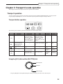
Chapter 3: Transport/Locate operation ................................... 39
Transport operation ........................................................................................................ 39
Transport button operation ...................................................................................... 39
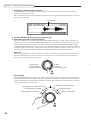
Using the [JOG] dial and the [SHUTTLE] dial .......................................................... 39
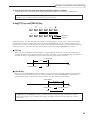
Using [TO] key and [FROM] key ............................................................................. 41
Locate operation ............................................................................................................ 42
Storing locate points ............................................................................................... 42
Moving to a locate point ......................................................................................... 43
Locating the zero position of the time counter ......................................................... 43
Locating the end point of a song ............................................................................. 44
Deleting a locate point from the locate list .............................................................. 44
Using the Quick Locate function ............................................................................. 44
Repeat function ...................................................................................................... 45
Using the [IN] and [OUT] keys to play data between the [IN] point
and the [OUT] point ............................................................................................... 46
Entering a time value in the counter ........................................................................ 47
Chapter 4: Punch In/Out ........................................................ 48
Manual Punch In/Out .................................................................................................... 48
Punch In/Out operation using the transport buttons ................................................. 48
Punch In/Out operation using a foot switch ............................................................. 49
Auto Punch In/Out ......................................................................................................... 50
Punch In/Out Rehearsal ................................................................................................. 51
Chapter 5: Assigning Input Signals and Virtual Tracks
(Assign Mode) ....................................................... 52
About Assign mode ........................................................................................................ 52
Switching between TRACK MIX and THRU MIX (THRU) ................................................ 52
Assigning input sources to tracks (SOURCE) ................................................................... 54
Assigning a virtual track to a physical track .................................................................... 56
TRACK ERASE function ........................................................................................... 57
Chapter 6: Mixer Function (Mixer Mode)............................... 58
About Mixer mode ......................................................................................................... 58
Basic operation in Mixer mode ...................................................................................... 58
Level/pan settings........................................................................................................... 61
LEVEL ..................................................................................................................... 61
PAN ........................................................................................................................ 61
Equalizer settings ........................................................................................................... 62
Turning the equalizer on/off (EQ ON/OFF) .............................................................. 62
Setting the frequency rate (EQ HIGH/MID/LOW FREQ) ........................................... 62
Setting the level (EQ HIGH/MID/LOW LEVEL) ........................................................ 63
Setting the band width (EQ MID WIDTH) ............................................................... 63
Displaying all EQ parameters of a given channel (STRIP) ................................................ 64
AUX send settings .......................................................................................................... 64
● When “2 MONO” is selected: ................................................................................ 64
Send level setting (AUX SEND-A(B)) ........................................................................ 64
Selecting PRE/POST (AUX A (B) PRE/POST) ............................................................. 65
vi
Table of contents
● When “STEREO” is selected: ................................................................................... 66
Send pan setting (AUX SEND PAN) ......................................................................... 66
Send level setting (AUX SEND LEVEL) ..................................................................... 66
Selecting PRE/POST (AUX PRE/POST) ..................................................................... 67
Other settings ................................................................................................................ 67
Channel ON/OFF (CHANNEL) ................................................................................ 67
SETUP .................................................................................................................... 68
MIDI settings (MIDI CONTROL) ............................................................................. 68
SCENE MEMORY ........................................................................................................... 69
Storing a scene ....................................................................................................... 69
Recalling a scene .................................................................................................... 69
Erasing a scene ....................................................................................................... 70
Chapter 7: Advanced technique for mixing ............................ 71
Mixing and recording several input signals ..................................................................... 71
Mixing several inputs via AUX ....................................................................................... 72
Digital input from an external device ............................................................................. 73
Using the Solo function .................................................................................................. 74
Using virtual tracks ........................................................................................................ 76
Digital ping-pong recording ........................................................................................... 77
Using an external effect unit for mixdown ...................................................................... 78
Adding sounds during mixdown ..................................................................................... 79
Chapter 8: Edit technique (Edit mode) ................................... 80
Using an Edit mode screen ............................................................................................. 80
Basic operations in Edit mode ........................................................................................ 81
Type and function of edit commands ............................................................................. 82
COPY
PASTE ................................................................................................... 82
COPY
INSERT ................................................................................................. 83
CUT
PASTE ..................................................................................................... 84
CUT
INSERT .................................................................................................... 84
INSERT SILENCE ..................................................................................................... 84
CUT
DISCARD ................................................................................................ 85
CUT
MOVE ..................................................................................................... 85
Chapter 9: Control Panel ........................................................ 86
Basic operation of the Control Panel ............................................................................... 86
Control Panel parameters ............................................................................................... 86
AUTO PUNCH (Setting Auto Punch In/Out points) .................................................. 86
VARI PITCH ............................................................................................................ 87
TIME DISPLAY (Setting the time counter display) ..................................................... 88
TIME OFFSET (offset of relative time) ....................................................................... 89
TO/FROM TIME (time settings for the [TO] key and [FROM] key) ............................ 90
PLAY MONITOR (selecting a monitoring source during playback) ...........................90
Sync (synchronization) ............................................................................................ 91
SAMPLING RATE .................................................................................................... 92
BEAT MAP .............................................................................................................. 92
TEMPO MAP .......................................................................................................... 93
FOOT SWITCH....................................................................................................... 94
vii
Table of contents
MIDI (Selecting a function of the MIDI OUT/THRU jack) ........................................ 94
LCD CONTRAST .................................................................................................... 94
OTHER (other setting) ............................................................................................. 95
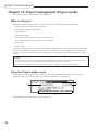
Chapter 10: Project management (Project mode)................... 96
What is a Project? .......................................................................................................... 96
Using the Project mode screen ....................................................................................... 96
Creating a new Project ................................................................................................... 97
Recalling a Project ......................................................................................................... 98
Erasing a Project ............................................................................................................ 98
Backing up a Project to an external device ..................................................................... 99
Reloading the backup Project ....................................................................................... 101
Chapter 11: Using a disk (Disk mode) .................................. 103
Notes on handling a disk ............................................................................................. 103
Using the Disk mode screen ........................................................................................ 103
Changing the current drive ........................................................................................... 104
Viewing the drive information ...................................................................................... 105
Formatting a disk ......................................................................................................... 106
Defragmenting a disk ................................................................................................... 107
Copying data in the disk .............................................................................................. 107
Using a removable drive .............................................................................................. 108
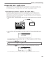
Chapter 12: MIDI applications ............................................. 109
Synchronizing an external device to the DPS12 (MTC) ................................................. 109
Synchronizing an external device to the DPS12 (MIDI Clock) ....................................... 110
Synchronizing the DPS12 to an external device (MTC) ................................................. 113
Controlling the DPS12 remotely from an external device (MMC) .................................. 114
Recording and playing back a scene memory of the mix parameters ............................ 115
Recording and playing back a mix automation ............................................................. 116
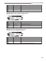
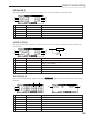
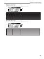
DPS12 MIDI Control Change Assign Table ............................................................ 118
Chapter 13: Using the effects ............................................... 119
Effect signal flow .......................................................................................................... 119
Global effects and Insert effects .................................................................................... 119
Using effects for mixdown ........................................................................................... 120
Selecting an effect type ......................................................................................... 120
Using effect return signals as analog inputs ........................................................... 121
Routing effect return signals to THRU MIX channels .............................................. 123
Setting the effect send level ................................................................................... 123
Adjusting the effect return level ............................................................................. 124
Recording sound to a track while applying an Insert effect ........................................... 125
Effect type and parameter ............................................................................................. 128
MONO CHORUS (G) ........................................................................................... 128
STEREO CHORUS (G)........................................................................................... 128
XOVER CHORUS(G) ............................................................................................. 129
MONO FLANGER (G)........................................................................................... 129
viii
Table of contents
STEREO FLANGER (G) .......................................................................................... 129
XOVER FLANGER (G) ........................................................................................... 130
PAN FLANGER (G) ............................................................................................... 130
MONO PHASER (I) ............................................................................................... 131
STEREO PHASER (I) .............................................................................................. 131
XOVER PHASER (I) ............................................................................................... 131
PAN PHASER (I) .................................................................................................... 132
PITCH SHIFT (I) .................................................................................................... 132
ROTARY SPEAKER (I) ............................................................................................ 133
AUTO PAN (I) ....................................................................................................... 133
TRIGGER PAN (I) .................................................................................................. 134
MONO DELAY (G) ............................................................................................... 134
PING PONG DELAY (G) ....................................................................................... 134
PANNING DELAY (G) ........................................................................................... 135
STEREO DELAY (G) ............................................................................................... 135
XOVER DELAY (G) ................................................................................................ 135
TAPE ECHO (G) .................................................................................................... 136
REVERB>SMALL ROOM (Small Room Reverb) (G) ................................................ 136
REVERB>BIG ROOM (Big Room Reverb) (G) ........................................................ 136
REVERB>SMALL HALL (Small Hall Reverb) (G) ..................................................... 137
REVERB>BIG HALL (Big Hall Reverb) (G) ............................................................. 137
REVERB>NON-LINEAR (Non-linear Reverb) (G) ................................................... 138
REVERB>REVERSE (Reverse Reverb) (G) ................................................................ 138
COMPRESSOR/LIMITER (I).................................................................................... 138
EXPANDER (I) ....................................................................................................... 139
NOISE GATE (I) ..................................................................................................... 139
DIGITAL EQ (I) ..................................................................................................... 139
AUTOWAH (I) ...................................................................................................... 140
TOUCH WAH (I) .................................................................................................. 140
CHORUS>DELAY (G) ........................................................................................... 140
FLANGE>DELAY (G) ............................................................................................. 141
PHASER>DELAY (G) ............................................................................................. 141
ix
Chapter 1: Outline of the DPS12
Chapter 1: Outline of the DPS12
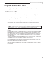
This chapter describes the features of the DPS12 and the name of its parts and functions. It also describes the
DPS12’s unique conceptual design and operating method. Akai recommends that you read this chapter thoroughly
even though you may already be quite familiar with multitrack recorders and mixing consoles.
Features of the DPS12
The DPS12 has the following features:
• The DPS12 includes a hard disk recorder that enables you to perform 12-track recording/playback, and a 20channel digital mixer. You can record and mix down on a single DPS12 as if you were using a multitrack
recorder.
• The DPS12 provides you with 12 recording/playback tracks (physical tracks) and 250 data storage tracks
(virtual tracks). Switching among virtual tracks that are assigned to physical tracks allows you to record
multiple takes of the same part or phrase and later select the best take for mixdown.
• The mixer section is fully loaded with EQ, Pan, two AUX sends, and Level capabilities. In addition to 12
TRACK MIX channels that control the output from the recorder tracks, 8 THRU MIX channels are available to
directly control input signals from the INPUT jacks.You can mix down the signal from a connected synthesizer, tone module, and/or external effect processor while playing back 12 tracks on the recorder section.
• A JAZ drive can be installed for removable media. Switching JAZ disks will expand the available recording
space without limits. Up to 1GB of data can be continuously recorded.
➸NOTE : This manual has been prepared based on the unit with Jaz drive installed internally. If your unit
is not equipped with Jaz drive, read Jaz drive in the manual as an appropriate drive connected.
• Up to six external hard disks and/or MO drives can be connected to the SCSI connector for backup and
recording.
• Connecting a MIDI device, such as a MIDI sequencer, allows for sync master or slave operation. Using MMC
(MIDI Machine Control) also enables you to remote-control the DPS12 from a connected external device.
• Up to 100 locate points in songs can be named and stored. You can immediately jump to any specified locate
point with an easy operation. A “Quick Locate function” that assigns locate points to the keys on the front
panel is also available.
• The DPS12 offers an improved and integrated edit function. You can specify track(s) to edit, and the range of
various editing operations, such as Copy & Paste, Cut & Paste, and Copy & Insert.
• The DPS12 is equipped with a scene memory that stores mix settings. You can create several mix configurations with different balance and EQ settings. You can also adjust the mix-related parameters via MIDI. Combining this with a MIDI sequencer will enable a mix automation.
• Installing an optional effect board, EB2M, will provide you with two-channel, internally-connected digital
effects. This enables you to handle all signals, from recording through the application of effects to mixdown, in
the digital domain.
1
Chapter 1: Outline of the DPS12
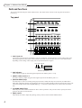
Parts and functions
This section describes the part names and functions. The names of the controls on the top panel are shown in
brackets [ ].
Top panel
1
2
INPUT
4
3
5
6
A
INPUT GAIN
B
C
OVER
OVER
1
LINE
OVER
OVER
2
MIC
LINE
OVER
3
MIC
4
LINE
MIC
LINE
OVER
5
MIC
LINE
6
MIC
LINE
MIC
RECORD SELECT
D
1
2
3
4
5
6
A
B
C
D
E
F
7
CHANNEL SELECT
E
8
H
G
QUICK LOCATE
1
2
3
4
5
6
7
8
1
2
3
4
5
6
7
8
1
2
3
4
5
6
7
8
C
C
C
C
C
C
C
C
F
R
L
1
R
L
2
R
L
3
R
L
R
L
4
5
R
L
6
R
L
7
R
L
L
8
G
1 INPUT jacks 1–6
Connect line-level electronic instruments, such as a synthesizer, and microphones to these analog input jacks.
The signal input from these jacks will be routed to the tracks of the recorder section or to the mixer section,
depending on the settings. These input jacks accept balanced stereo signals.
Hot Cold Ground
Balanced signal input
2 Peak indicators
These indicators light up when the signals input from the INPUT jacks 1–6 clip.
3 [INPUT GAIN] controls 1–6
Use these controls to adjust the gain of the signals input from the INPUT jacks 1–6.
4 [RECORD SELECT] keys
Use these keys to select a recording track (physical track). When these keys are turned on, the LEDs above
them flash, indicating that the corresponding tracks enter recording-standby mode. Pressing the keys again will
cancel the standby mode. When the [SOLO] key (J) is turned on, these buttons are used to select solo channels.
5 [CHANNEL SELECT] keys
These keys are used to select channels for edit or mixer operations. They are also used to specify the locate
point for the Quick Locate function.
6 [PAN] controls
These knobs are used to adjust the panning (stereo position) of the TRACK MIX channels.
2
Chapter 1: Outline of the DPS12
7 Channel faders
These faders control the level of TRACK MIX channels.
DIGITAL PERSONAL STUD
H
F1
I
M
F2
N
F3
O
F4
P
F6
F5
Q
R
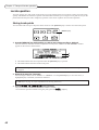
8 Display
This LCD display indicates various information required for operating the DPS12, such as the time counter
and level meter.
9 Function keys ([F1] – [F6])
These keys are used to execute or turn on/off the functions that appear on the bottom row of the display.
F2
N
F3
O
F4
P
SOLO
J
CANCEL
F6
F5
Q
L
M
R
JOG PLAY
N
NUMBER/NAME
K
ENTER
O
J [SOLO] ([CANCEL]) key
This key enables the Solo function in the mixer section. When this key is turned on, you can monitor the tracks
selected via the [RECORD SELECT] keys. It is also used as a [CANCEL] key to cancel the entry of numeric
values or characters.
K [NUMBER/NAME] ([ENTER]) key
This key enables the input of numeric values and characters. When this key is turned on, the LED above this
key flashes, and you can enter the numbers, alphabets, and symbols, using the keys on the top panel that have
the corresponding labels below them. This key is also used as an [ENTER] key that confirm the entry of the
values and characters.
L [JOG] dial
This dial is used to change the setting or value of an item selected by the cursor on the display. When the [JOG
PLAY] key N is turned on, you can perform jog-playback depending on the speed and direction in which you
rotate the dial.
M [SHUTTLE] dial
This dial is used to select one digit of a time field value to be changed that was displayed via the [JOG] dial.
When the [JOG PLAY] key N is turned on, you can perform shuttle-playback depending on the angle and
direction of this dial.
N [JOG PLAY] key
This key enables jog-playback and shuttle playback. When this key is turned on, the waveform of a selected
channel appears on the display, and you can perform jog-playback via the [JOG] dial and shuttle-playback via
the [SHUTTLE] dial.
3
Chapter 1: Outline of the DPS12
O [CURSOR] key
The cursor key is used to move the cursor (highlighted part) on the display to select an item to set.
P
MASTER
TRACK
VIEW
ASSIGN
DISK
PROJECT
UNDO
S
T
U
V
W
MIXER
EDIT
IN
OUT
TO
FROM
X
Y
Z
&
#
SPACE
MAIN
EDIT POINT
PLAY
Q
R
S
LOCATE
GO TO
MEMORY
T
U
V
P Mode keys ([MAIN] key / [TRACK VIEW] key / [ASSIGN] key / [DISK] key / [PROJECT] key / [MIXER]
key / [EDIT] key)
These keys are used to switch among various operating modes (MAIN mode, TRACK VIEW mode, MIXER
mode, etc.). The [MAIN], [TRACK VIEW], and [MIXER] keys are effective even during the recording or playback
operation, while the other keys are effective only when the operation is stopped.
Q [UNDO] key
This key is used to cancel the recording or editing operation you just performed. When you press this key right
after you perform recording or editing, the previous status is restored and the LED above the [UNDO] key
lights up (Undo). Pressing the [UNDO] key again restores the status obtained when you performed the recording or editing operation, and the LED turns off (Redo).
✐TIP : The range of the Undo level parameter (to set how many previous operations can be restored via
the [UNDO] key) is 0 to 250. If the Undo level is set to “2” or higher, press the [UNDO] key, then enter the
number of possible undo operations.
R Edit point keys ([IN] key / [OUT] key)
These keys are used to store IN/OUT points that are used to specify the range for the Auto Punch In/Out
function and Edit function.
S Edit play keys ([TO] key / [FROM] key)
These keys are used for the Edit Play function that plays back data from or to the current stop position.
T Locate keys ([MEMORY] key / [GO TO] key)
These keys are used to store the locate point (the position information in a song) and move the current position
on the DPS12 to any locate point.
U Transport buttons
These keys are used to control the transport operation of the DPS12, such as recording, playback, stop, etc.
Each button has the following function:
•
[REC] button ............ This button is used to record. Pressing the [
] button while holding down the [REC]
button causes a track with its [RECORD SELECT] key on to enter recording mode.
Recording mode is also entered when you press the [REC] button while holding down
the [
] button during playback (Punch In).
•
[
] button ............. This button is used to play back data. Pressing this button during recording cancels
recording, and playback continues (Punch Out).
•
4
[
] button ............. This button is used to stop recording, playback, fast forward, and rewind.
Chapter 1: Outline of the DPS12
•
[
] button ............ This button is used to rewind. Pressing this button while the transport section is
stopped causes the time counter on the display to count backward at high speed.
Pressing and holding down this button during playback causes fast reverse playback
for as long as you hold it down (Review).
•
[
] button ............ This button is used to fast forward. Pressing this button while the transport section is
stopped causes the time counter on the display to count forward at high speed.
Pressing and holding down this button during playback causes fast playback for as
long as you hold it down (Cue).
V [MASTER] fader
This fader adjusts the master level of the mixer section.
Front panel
PHONES
LEVEL
MIN
A
MAX
B
C
1 PHONES (headphones) jack
Connect monitoring headphones to this jack, which outputs the same signal as that output from the MASTER
OUT jacks on the rear panel.
2 LEVEL (headphones level) control
This control adjusts the volume level of the headphones connected to the PHONES jack.
3 Internal drive (JAZ drive)
This is reserved for mounting internal drive.
Rear panel
FOOT SW.
SCSI
F
E
POWER
ON
H
MIDI
OUT / THRU
OPTICAL
IN
OUT
IN
AUX SEND
A
B
MASTER OUT
L
R
OFF
G
D
C
B
A
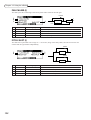
1 MASTER OUT L/R jacks
These jacks output a stereo signal that is a mix of each channel (TRACK MIX channels + THRU MIX
channels) of the mixer section.
2 AUX SEND (AUX send) A/B jacks
These jacks output a signal from each channel of the mixer section (TRACK MIX channels + THRU MIX
channels) to Send A/B. (If AUX TYPE is set to STEREO, a left signal and right signal will be output from jack
A and jack B respectively.)
5
Chapter 1: Outline of the DPS12
3 OPTICAL IN/OUT jacks
These jacks are used to transmit digital audio signals to and from a connected external digital device, such as a
DAT recorder. Depending on the settings, digital signals input from the OPTICAL IN jack are sent to the
tracks in the recorder section (physical tracks), or directly to the mixer section. The OPTICAL OUT jack
outputs the same signal as the digital signal output from the MASTER OUT jacks 1.
4 MIDI IN, OUT/THRU connectors
These connectors are used to transmit sync signals and control signals to and from a connected external MIDI
device, such as a MIDI sequencer.
5 SCSI connector
This connector is used to connect an external hard disk or MO drive.
6 FOOT SW. (foot switch) jack
This jack is used to connect a foot switch to control the Punch In/Out operation and playback/stop operation
with your foot.
7 POWER switch
This switch turns on/off the power to the DPS12.
8 Power connector
Connect the included power cable here.
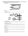
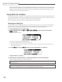
Using a JAZ drive
If you have a JAZ drive installed on the DPS12, you can store audio data and other information on a JAZ disk
inserted in the drive’s slot. A JAZ disk is a storage medium with a capacity of 1 GB, and can accommodate audio
data of up to three hours sixteen minutes (at a sampling rate of 44.1kHz in monaural).
Disk slot
Eject button
Access indicator
Eject hole
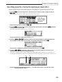
Inserting and ejecting a JAZ disk
Follow the procedure below to insert and eject a JAZ disk.
■ Inserting a JAZ disk
1. Make sure that the power to the DPS12 is turned on.
CAUTION : Be sure to turn on the power to the DPS12 before you insert a JAZ disk into the optional
JAZ drive. Never force the disk.
2. Hold the JAZ disk with the label side facing up and the metal shutter side directed toward the slot,
then insert the disk into the drive.
6
Chapter 1: Outline of the DPS12
PHONES
LEVEL
MIN
MAX
JAZ
■ Ejecting a JAZ disk
1. Press the eject button on the JAZ drive.
The access indicator flashes for a while, then the JAZ disk is ejected about 2 cm beyond the slot.
2. Remove the disk carefully.
Insert the disk in the case that came with the disk, and store it in a safe place.
CAUTION : Never force a JAZ disk in or out of its slot. Doing so may damage not only the disk but the
JAZ drive.
➸NOTE : If you need to eject a JAZ disk while the power to the DPS12 is turned off, insert and gently
push a thin wire or a straightened paper clip into the eject hole of the JAZ drive to eject the disk. Akai is
not responsible for damage to the JAZ disk or loss of data caused by a forced eject operation.
Notes on using a JAZ drive
• To be able to use a JAZ disk on the DPS12, you need to format a disk first. (Refer to page 22, 106 for information on how to format a disk.)
• Make sure that the power to the DPS12 is turned on when you insert or eject a JAZ disk. If you turn on or off
the power to the DPS12 while a JAZ disk is inside the drive, the disk may be damaged and data may be lost.
• The JAZ drive automatically enters sleep mode (disk spinning is stopped) if it is not accessed for about 30
minutes. Therefore, it may take a while to exit sleep mode if you start playing back or recording after a period
of time. This is not a malfunction.
• After you eject a JAZ disk from the drive, always store the disk in its protective case.
• Do not open, apply any force, or drop liquid on the shutter of a JAZ disk. Otherwise, the disk may be damaged
and data may be lost.
• When the access indicator (an LED on the front panel) of the JAZ drive is lit, do not move the DPS12. Remove
the JAZ disk before moving the DPS12.
• The eject button is disabled while the DPS12 accesses data on the disk (such as while recording or playing).
• Do not open the dust door of the JAZ drive slot manually. Do not insert anything other than a JAZ disk into the
disk slot. Otherwise, dust may enter the drive or the JAZ drive may be damaged.
• If a JAZ disk is damaged for some reason, its data will be lost forever. We recommend that important data be
backed up to an external hard disk or an MO drive. (Refer to page 99 for information on backing up data.)
7
Chapter 1: Outline of the DPS12
About external SCSI devices
The rear panel of the DPS12 is equipped with a half-pitch 50-pin SCSI connector (SCSI-2 standard), which you
can connect to an external hard disk or MO drive to back up, record, or play back data.
➸ NOTES :
• Some models of external SCSI devices may not be compatible with the DPS12. Also, you may not be able to
record or playback, or you may have only a limited number of tracks available for simultaneous multitrack
recording and playback.
• Consult AKAI technical support for more information on the manufacturers and models of external SCSI
devices that are compatible with the DPS12.
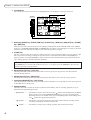
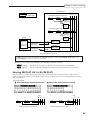
Connecting an external SCSI device
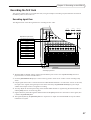
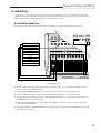
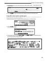
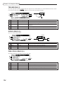
■ Connecting a single SCSI device
Use a SCSI cable to connect the DPS12 and one SCSI device.
SCSI cable
Terminator
SCSI connector
INPUT
External hard disk
or MO drive
dps12
INPUT GAIN
DPS12
Example of connecting a single SCSI device to the DPS12
Install a terminator on the SCSI device. If the SCSI device has a built-in active terminator, turn it on. (Refer to
the instruction manual that came with the SCSI device for more information on how to turn on the active
terminator.) Set the SCSI ID number of the external SCSI device to any number other than 4 or 6.
✐TIPS :
• A terminator is a device that terminates the end of the SCSI connection. Usually, you install the terminator on the SCSI device on the SCSI connector that is not connected to the SCSI cable. Some SCSI devices
may have a built-in active terminator that performs termination electrically. In this case, turn the
terminator on/off using the dedicated switch.
• SCSI devices recognize and identify each other using an identification of 0–7 called the SCSI ID. The
factory SCSI ID setting of the DPS12 is 6 (changeable), and the ID of the JAZ drive is 4 (fixed). You
need to use other numbers as SCSI IDs for other connected SCSI devices.
8
Chapter 1: Outline of the DPS12
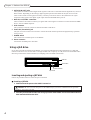
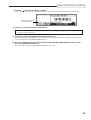
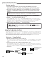
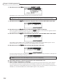
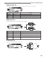
■ Connecting multiple SCSI devices
Use a daisy chain connection to connect multiple SCSI devices as shown below:
SCSI cable
To a SCSI
connector
External hard disk
or MO drive
INPUT
dps12
INPUT GAIN
DPS12
External hard disk
or MO drive
Terminator
External hard disk
or MO drive
Connecting multiple SCSI devices
Install a terminator on the last SCSI device in the daisy chain. (If the SCSI device has a built-in active terminator, turn it on.) The default SCSI ID of the JAZ drive is set to 4 and the SCSI ID of the DPS12 is set to 6.
Therefore, set the SCSI ID of all external SCSI devices to a number other than 4 or 6.
CAUTION : Turn off the power to all devices before performing SCSI connection.
➸NOTES :
• Use a short, high-quality SCSI cable, if possible. Using too long a cable or a low-quality cable may
cause an error.
• You need to format the disk before you can use the external hard disk or MO drive connected to the
DPS12. (Refer to page 22, 106 for more information on how to format the disk.)
• To record and play back data to the connected hard disk or MO drive, you need to specify the drive as
the current drive (currently selected drive). (Refer to page 104 for more information on how to specify
the current drive.)
• You cannot record one continuous stream of data to multiple disks.
9
Chapter 1: Outline of the DPS12
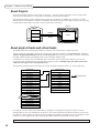
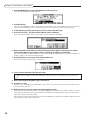
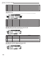
About Projects
The DPS12 manages songs by treating them as “Projects.” A Project contains audio data, mixer settings, locate
points (position information in a song), and scene memory (mix parameter settings).
The internal hard disk can store multiple Projects. However, the DPS12 can handle only one Project at a time.
When the power to the DPS12 is turned on, the DPS12 reads the first Project in the disk. You may want to specify
another Project on the disk to be read or create a new Project, if necessary.
DPS12
Disk
INPUT
dps12
INPUT GAIN
Project
Reading
Project
Project
Project
Storing
JAZ
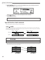
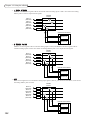
About physical tracks and virtual tracks
The DPS12 performs recording and playback by assigning 250 virtual tracks to 12 physical tracks.
“Physical track” is a track that is used to record, play back, and edit in normal way. Physical tracks 1–12 correspond to the [RECORD SELECT] 1–12 keys on the top panel. Pressing any of these keys causes the corresponding LED to flash and the corresponding track to enter recording standby mode.
“Virtual track” is used to store recorded audio data. You cannot control virtual tracks. However, you can still
record, play back, and edit them by assigning them to physical tracks. The DPS12 provides 250 virtual tracks,
which you can assign to any of 12 physical tracks.
The following example shows Virtual tracks 3, 10, and 6 assigned to physical tracks 1, 2, and 3 respectively.
Virtual Track
Physical Track
Virtual Track 1
Track 1
Virtual Track 2
Track 2
Virtual Track 3
Track 3
Virtual Track 4
Track 4
Virtual Track 5
Track 5
Virtual Track 6
Track 6
Virtual Track 7
Track 7
Virtual Track 8
Track 8
Virtual Track 9
Track 9
Virtual Track 10
Track 10
Virtual Track 11
Track 11
Virtual Track 12
Track 12
Mixer section
Virtual Track 13
Virtual Track 14
Virtual Track 15
Virtual Track 16
Virtual Track 246
Virtual Track 247
Virtual Track 248
Virtual Track 249
Virtual Track 250
For example, you can switch virtual tracks that are assigned to recording tracks (physical tracks) to record
multiple takes of your solo performance. In this way, you can later select the best take for mixdown. You can also
store data in a virtual track to perform ping-pong recording onto the data repeatedly until you are satisfied. Virtual
tracks have various applications, and you can use the DPS12 without being limited to twelve tracks.
✐TIP : You can also name virtual tracks.
10
Chapter 1: Outline of the DPS12
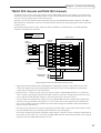
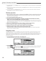
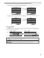
TRACK MIX channels and THRU MIX channels
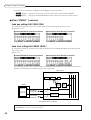
The DPS12’s mixer section offers eight channels (called “THRU MIX channels”) that enable you to control input
signals that come directly from the INPUT jacks, as well as twelve channels (called “TRACK MIX channels”) that
you can control for panning and level from the top panel.
Normally, you can record and mix down audio data using only the TRACK MIX channels. However, the THRU
MIX channels are useful when you wish to overdub external sound sources while playing back twelve tracks in the
recorder section.
The following diagram shows a basic signal flow. When the DPS12 is in default status, use the TRACK MIX
channels to record and mix down data.
Analog signal
Digital signal
Mixer section
INPUT
(ANALOG)
1
GAIN
2
GAIN
3
GAIN
4
GAIN
5
GAIN
6
GAIN
Recorder
section
Input
Assign
OPTICAL IN
(DIGITAL)
OPTICAL OUT
(DIGITAL)
Tr1
Tr2
Tr3
Tr4
Tr5
Tr6
Tr7
Tr8
Tr9
Tr10
Tr11
Tr12
L R
TRACK MIX channel
1
2
3
4
5
6
7
8
9
10
11
12
LEVEL
LEVEL
LEVEL
LEVEL
LEVEL
LEVEL
LEVEL
LEVEL
LEVEL
LEVEL
LEVEL
LEVEL
PAN
PAN
PAN
PAN
PAN
PAN
PAN
PAN
PAN
PAN
PAN
PAN
MASTER LEVEL
MASTER OUT L
(ANALOG)
R
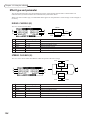
A typical signal flow when only TRACK MIX channels are used
• Signals input from the INPUT jacks (analog/digital) are adjusted for the gain via the GAIN controls, then
routed to the Input Assign section and assigned to each physical track. (Track assignment is performed in
Assign mode. See page 52 for more information.)
• Physical tracks 1–12 of the recorder section are directly routed to TRACK MIX channels 1–12 of the mixer
section. Usually, input signals routed from the INPUT jacks are sent from recording-ready tracks to the mixer
section, and the recorder playback signals are sent from other tracks to the mixer section.
• You can set the level and pan of the signals sent to the TRACK MIX channels, using the faders and the PAN
controls on the top panel before mixing down to a stereo signal. You can also adjust the mix-related parameters, such as channel on/off, EQ, and AUX send A/B. (These settings are available in Mixer mode. Refer to
page 58 for more information.)
• The master level of the stereo mix signal is adjusted by the master fader on the top panel. This signal is output
from the MASTER OUT jacks (analog) and the OPTICAL OUT jacks (digital).
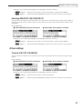
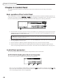
You can also send the input signals at the INPUT jacks directly to the mixer section, instead of sending them to
the recorder section. In this case, you can use the THRU MIX channels. The following diagram shows a typical
signal flow when the THRU MIX channels are used.
11
Chapter 1: Outline of the DPS12
Analog signal
Digital signal
Mixer section
L R
INPUT
(ANALOG)
1
GAIN
2
GAIN
3
GAIN
4
GAIN
5
GAIN
6
GAIN
OPTICAL IN
(DIGITAL)
THRU MIX channel
1
2
3
4
5
6
DL
DR
Recorder
section
Tr1
Tr2
Tr3
Tr4
Tr5
Tr6
Tr7
Tr8
Tr9
Tr10
Tr11
Tr12
OPTICAL OUT
(DIGITAL)
LEVEL
LEVEL
LEVEL
LEVEL
LEVEL
LEVEL
LEVEL
LEVEL
PAN
PAN
PAN
PAN
PAN
PAN
PAN
PAN
TRACK MIX channel
1
2
3
4
5
6
7
8
9
10
11
12
LEVEL
LEVEL
LEVEL
LEVEL
LEVEL
LEVEL
LEVEL
LEVEL
LEVEL
LEVEL
LEVEL
LEVEL
PAN
PAN
PAN
PAN
PAN
PAN
PAN
PAN
PAN
PAN
PAN
PAN
MASTER LEVEL
MASTER OUT L
(ANALOG)
R
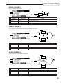
A typical signal flow when both TRACK MIX channels and THRU MIX channels are used
• You can route each input signal to a THRU MIX channel or to the recorder section individually. In this
example, all input signals are sent to the THRU MIX channels. (This routing is done in Assign mode. Refer to
page 52 for more information.)
• You can also set the mix-related parameters, such as the level, pan, channel on/off, EQ, and AUX send A/B, for
the signals sent to the THRU MIX channels, as well as the signals sent to the TRACK MIX channels. Use
Mixer mode to set the mix parameters for the THRU MIX channels. You cannot control the level and pan from
the top panel. (Refer to page 58 for more information on Mixer mode.)
• The stereo mix signal of the THRU MIX channels and TRACK MIX channels is adjusted for the master level
by the master fader on the top panel, then output from the MASTER OUT jacks (analog) and the OPTICAL
OUT jacks (digital).
• You can use two-channel (A/B) internal effects in the digital domain if you have an optional effects board
EB2M installed. In this case, each channel’s AUX send A/B functions as an effect send. The return signal from
the internal effects can be routed to the tracks for recording, or routed directly to the mixer section via the
THRU MIX channels.
12
Chapter 1: Outline of the DPS12
ABLR
SOLO
LEVEL
MIXER
THRU
INPUT
GAIN
INPUT 1 (analog)
THRU EQ
MIXER
THRU
ASSIGN
THRU
SEND A
PRE/POST
SEND B
PRE/POST
INPUT 2 (analog)
PAN
SEND A
LEVEL
INPUT 3 (analog)
SEND B
LEVEL
INPUT 4 (analog)
ASSIGN
INPUT 5 (analog)
SOURCE
ASSIGN
INPUT 6 (analog)
SOLO
LEVEL 1-12
FX RTN
TRACK EQ
INPUT L (digital)
PAN
1-12
INPUT R (digital)
SEND A
PRE/POST
SEND B
PRE/POST
SEND A
LEVEL
SEND B
LEVEL
PLAY MONITOR
MAIN
REC
PLAY
CONTROL PANEL
MIXER
TRACK
PHYSICAL TRACK
ASSIGN
V.TRK
VIRTUAL TRACK
MIXER
THRU
HARD DISK
SEND-A
MASTER
MULTI
MULTI
ASSIGN
FX RTN
AUX SEND A
AUX SEND B
MIXER
EFFECT
SEND-B
MASTER
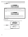
MASTER OUT L (analog)
MASTER OUT R (analog)
DIGITAL OUT L (digital)
DIGITAL OUT R (digital)
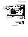
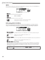
* Any effects operation requires
an optional EB2M effect board
installed.
MASTER
LEVEL
* AUX mode is set to stereo.
ABLR
THRU signal
SOLO
LEVEL
PAN
or
TRACK playback signal
AUX SEND
PRE/POST
SEND
LEVEL
SEND
PAN
Signal block diagram
13
Chapter 1: Outline of the DPS12
About a scene memory
The DPS12 can store a set of mix parameter settings as a scene, and recall the scene later. A scene is stored as part
of the Project in the disk. You can store multiple scenes in one Project. For example, you may store multiple
scenes with different balance and EQ settings for mixdown, and audition and compare different mixes.
The following main parameters are stored in a scene.
• Channel level/master level settings (See page 61.)
• Channel panning (See page 61.)
• Channel AUX send A/B settings (send level, pre/post selection) (See page 64.)
• Channel EQ setting (See page 62.)
About DPS12’s user interface
This section explains the basic operation of the DPS12, such as using the display and changing the values.
Using the display
Various information required for operating the DPS12, such as the current position, mix parameter settings, etc.,
appears on the display. The information varies depending on which key you operate (such as a mode key, edit
point key, locate key, etc.).
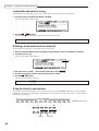
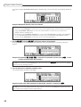
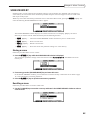
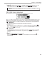
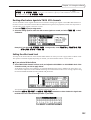
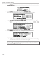
■ Screen
A display that appears when you press a mode key is called “screen.” For example, the following display is a
MAIN screen that is recalled when you turn on the power to the DPS12 or when you press the [MAIN] key. You
will use this screen for recording and playback.
C
MAIN screen
A
B
D
6
E
The MAIN screen shows the following information:
1 Time counter ........... Indicates the current transport position. You can enter a value into the time counter to
move to a desired position.
✐TIP : The DPS12 displays the time counter using hour, minute, second, frame, and sub-frame unit. The
term “frame” is borrowed here from the world of motion picture film and video, in which each still image
from the sequence of images that appear or a strip of film is called a “frame.”You can change the number
of frames in the Control Panel (page 88). A sub-frame is a unit obtained by dividing a frame by ten.
hour minute second
sub-frame
frame
2 Level meter .............. Indicates the output level of the physical tracks, the input level at the INPUT jacks, or
the output level of the AUX send A/B or the master output.
3 Project name ........... Indicates the name of the Project you are currently working on.
4 Remaining time ....... Indicates the remaining time available for recording on the disk.
14
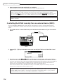
Chapter 1: Outline of the DPS12
5 Busy meter .............. This meter indicates that the disk is being accessed. The more the meter is moves, the
more frequently the disk is being accessed.
6 Disc access indicator ... This indicator lights up when the disk is being accessed.
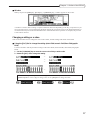
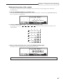
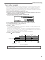
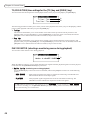
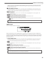
Pressing any mode key other than the [MAIN] key in the MAIN screen will show the screen of the corresponding mode. For example, pressing the [TRACK VIEW] key will switch to Track View mode and the
TRACK VIEW screen will appear.
The TRACK VIEW screen indicates the length of recorded data for each physical track in a bar graph. Remember that depending on which mode key you press, the screen will change.
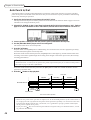
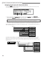
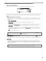
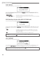
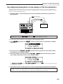
■ Function key display
Sometimes, function names appear on the bottom of the screen as shown below. These are the functions that
correspond to function keys ([F1] key – [F6] key).
[F1]
[F2]
[F3]
[F4]
[F5]
[F6]
Function keys are special keys in that each of them does not have a single fixed function, but has different
functions depending on the screen currently shown in the display. For example, pressing the [F2] key in the
DISK SETUP screen as shown above will execute the disk format function.
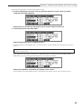
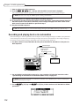
■ Control panel
Pressing one of the [F3] – [F6] keys in the [MAIN] screen will switch the screen to the Control Panel screen as
shown below.
MAIN screen
↓
Press one of [F3] – [F6] keys.
↓
Control Panel
The Control Panel screen is used to set various parameters on the DPS12. Pressing a mode key after the setting
is complete will take you to the corresponding mode screen.
15
Chapter 1: Outline of the DPS12
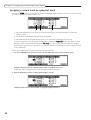
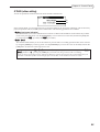
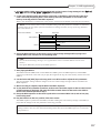
■ Field and cursor
The parameter values that are shown on the display and that can be modified are called “fields.” The highlighted part of the screen is called the “cursor.” The field currently highlighted by the cursor indicates that the
field is selected for editing. If there are multiple fields in a screen, use the [CURSOR] key to move the cursor to
the desired field.
CURSOR
Fields are categorized as follows:
• Select field
This type of field offers options you choose from.
• Numeric field
In this type of field, you can change the parameter value.
• Time field
In this type of field, you can change the time on the counter and the locate point.
• Character field
This type of field is used to name the locate point, virtual tracks, and Projects.
• Graphic field
This type of field indicates the mix parameter settings graphically.
16
CURSOR
Chapter 1: Outline of the DPS12
■ Window
When you press the [UNDO] key, [GO TO] key, or [MEMORY] key, a window appears on the screen.
A window is used to make a setting or operate a function that varies depending on the key you pressed. As you
do in a normal screen, you can change the parameter settings by moving the cursor to the desired parameter, or
use the function keys to execute the desired function. After the function or operation is complete, the previous
screen will be restored.
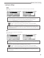
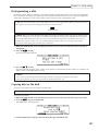
Changing a setting or a value
This section describes how to change the time on the counter, and the settings and values of the fields.
■ Using the [JOG] dial to change the setting (select field/numeric field/time field/graphic
field)
Use the JOG dial to edit the parameter settings of the select fields, numeric fields, time fields, and graphic
fields.
1. Use the [CUROSOR] key to move the cursor to the field you wish to edit.
2. Rotate the [JOG] dial to change the setting.
→
→
→
→
✐TIP : Use the [SHUTTLE] dial to select a digit to edit when a time field is selected. First rotate the
[SHUTTLE] dial to select a digit to change, then use the [JOG] dial to change the value.
→
→
17
Chapter 1: Outline of the DPS12
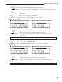
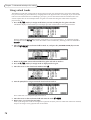
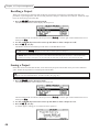
■ Entering a numeric value directly (time counter/time field)
You can use the keys on the top panel to directly enter a value for the time counter, and time field on the MAIN
screen. Follow the steps below:
1. Use the [CURSOR] key to move the cursor to a time field.
➸NOTE : You do not need this step when you enter the time for the time counter in the MAIN screen.
2. Press the [NUMBER/NAME] key.
The [NUMBER/NAME] key’s LED flashes, and the keys on the top panel function as numeric keys.
3. Use the [CHANNEL SELECT] 1–10 keys to enter a desired number (1–9, 0).
The [CHANNEL SELECT] 1–10 keys function as numeric keys 1–9, 0.
For example, if you wish to enter 1 hour 25 minutes 43 seconds for the time counter or a time field, press
the [CHANNEL SELECT] 1–10 keys in the following order:
→
→
→
→
→
4. Press the [NUMBER/NAME] key again.
This time, the [NUMBER/NAME] key functions as an [ENTER] key. The [NUMBER/NAME] key’s LED turns
off, and the entered number is confirmed. If you wish to cancel the entered number, press the [SOLO] key
(which functions as a [CANCEL] key) to go back to the previous display.
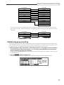
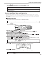
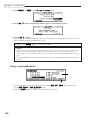
■ Using the [JOG] dial to enter characters (character field)
1. Use the [CURSOR] key to move the cursor to a character field.
2. Press the [NUMBER/NAME] key.
The [NUMBER/NAME] key’s LED flashes and an underline appears under the first character in the character
field. This underline indicates that you can enter a character.
3. Rotate the [JOG] dial to select a character to enter.
The following numbers, letters, and symbols can be selected by the [JOG] dial.
B C D E
F
G H
I
J
K
L M N O P Q R
S
T
U
V W X
Y
Z
[
¥
]
^
_
¬
18
A
a
b
c
e
f
g
h
i
j
k
l
m n
o
p
q
r
s
t
u
v
w
x
y
z
{
|
}
¯ X
!
"
#
$ % &
'
(
)
*
+
,
-
.
0
1
2
3
4
5
6
7
8
9
:
;
<
=
>
? @
d
/
Chapter 1: Outline of the DPS12
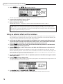
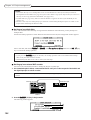
4. Use the [CURSOR] key or the [SHUTTLE] dial to move the underline to the second character
position.
While the [NUMBER/NAME] key’s LED is flashing, you can move the underline back and forth using the
[CURSOR] key or the [SHUTTLE] dial.
5. Repeat Steps 3 and 4 to complete naming.
If you enter a wrong character, use the [CURSOR] key or the [SHUTTLE] dial to move the underline to the
character you wish to correct.
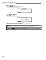
6. Press the [NUMBER/NAME] key again.
This time, the [NUMBER/NAME] key functions as an [ENTER] key. The [NUMBER/NAME] key’s LED turns
off, and the entered characters are confirmed. If you wish to cancel the entered character, press the [SOLO]
key (which functions as a [CANCEL] key) to return to the previous display.
■ Entering characters directly (character field)
You can enter characters directly into a character field by using the keys on the top panel.
1. Use the [CURSOR] key to move the cursor to a character field.
2. Press the [NUMBER/NAME] key.
The [NUMBER/NAME] key’s LED flashes, and the keys on the top panel function as number/letter keys.
Alphabets, numbers, and symbols are printed below the keys. The following characters can be entered.
3
4
5
6
7
W X Y
1
2
Z
&
#
(Space)
8
9
0 A
B C D
E
F G H
I
J
K
L M N O P Q R S
T U V
3. Press the key that corresponds to an alphabet, number, or symbol you wish to enter.
The character that corresponds to the pressed key is entered and the underline moves to the right.
4. Repeat Step 3 repeatedly to complete naming.
5. Press the [NUMBER/NAME] key again.
This time, the [NUMBER/NAME] key functions as an [ENTER] key. The [NUMBER/NAME] key’s LED turns
off, and the entered characters are confirmed. If you wish to cancel the entered character, press the [SOLO]
key (which functions as a [CANCEL] key) to return to the previous display.
19
Chapter 2: Recording on the DPS12
Chapter 2: Recording on the DPS12
This chapter describes basic operations of the DPS12, including recording preparation, recording the first part,
overdubbing, mixdown to a master recorder.
Connections
The diagram below is an example of basic connections for recording on the DPS12.
Monitor system
Master recorder
(DAT recorder/MD recorder)
DIGITAL
IN
DIGITAL
OUT
LINE IN
Sampler
DIGITAL OUT
Effect processor,
direct box, pre-amp, etc.
OPTICAL
OUT
OPTICAL
IN
MASTER
OUT
INPUT
DIGITAL PERSONAL STUDIO
Synthesizer/rhythm machine
dps12
INPUT GAIN
AUX SEND A/B
External effect processor
Dynamic microphone
PHONES
DPS12
Headphones
CAUTION : Make sure that you turn off the power to all equipment before making connections.
➸ NOTE : DIGITAL OUT jacks on AKAI sampler are of the coaxial type. You will need an optical converter to
connect a sampler to input digital signals to the DPS12.
20
Chapter 2: Recording on the DPS12
■ Connecting sound sources
You can connect line-level instruments, such as a synthesizer or a rhythm machine, and dynamic microphones
directly to INPUT jacks 1–6. We recommend that you connect instruments with a high output impedance, such
as an electric guitar or a bass guitar, via a compact effect processor, pre-amp, or direct box.
■ Connecting a monitor system
Connect a monitor system, such as audio equipment, to the MASTER OUT jacks. If you are using the DPS12
with a master recorder connected all the time, connect the output jacks of the master recorder to the monitor
system.
■ Connecting a master recorder
If you use a master recorder that has digital input jacks, such as a DAT recorder or an MD recorder, connect
the OPTICAL OUT jacks of the DPS12 to the digital input jacks of the master recorder, and the output jacks of
the master recorder to the monitor system.
✐TIP : If the digital I/O jacks of the master recorder are coaxial, you will need an optical/coaxial
converter.
Similarly, if you use an analog recorder as the master recorder, connect the MASTER OUT jacks of the DPS12
to the input jacks of the master recorder, and the output jacks of the master recorder to the monitor system.
In either case, switch the master recorder to input monitoring status (monitoring the input signal) in order to
record or play back on the DPS12, and switch the recorder to tape monitoring status (monitoring the playback
sound) in order to play back the master recorder.
■ Connecting a device that has digital output jacks
To input signals from a device that has digital output jacks, such as a DAT recorder, MD recorder, sampler,
etc., into the DPS12, connect the digital output jacks of the external device to the OPTICAL IN jacks of the
DPS12.
➸NOTE : When you connect digital inputs, make sure that the sampling rate of the connected digital
device matches that of the DPS12. (See page 73.)
■ Connecting an external effect unit
To use external effects, such as reverb and delay, connect the AUX SEND A/B jacks of the DPS12 to the input
jacks of the external effect unit, and the output jacks of the effect units to the INPUT jacks of the DPS12.
21
Chapter 2: Recording on the DPS12
Preparing to record
This section explains the necessary preparations for recording.
Turning on the power to the DPS12
1. Turn on the power to the peripheral devices, excluding the DPS12 and the monitor system.
The sequence for turning on the power to each device is: peripheral devices (such as tone generator, external
SCSI device)
DPS12
monitor system.
Reverse this order when you turn off the power.
2. Turn on the power to the DPS12.
CAUTION : Do not insert a JAZ disk into the JAZ drive on the front panel before you turn on the power
to the DPS12. If you turn the power on or off while a JAZ disk is inserted in the drive, the disk may be
damaged and recorded data may be lost.
When you turn on the power to the DPS12, the following initial screen appears.
3. Press the SKIP [F6] key.
The following screen (called the MAIN screen) appears on the display.
4. Turn on the power to the monitor system.
Formatting a JAZ disk
Before you can use a JAZ disk on the DPS12, you first need to format the disk. Follow the procedure below to
format a disk. (Ignore this procedure if you use a pre-formatted disk.)
1. Insert a JAZ disc into the JAZ drive.
2. Press the [DISK] key.
The display changes as follows:
This is a DISK SETUP screen where you can make settings for the JAZ drive or an external hard disk. In this
example, the screen shows the status of connected drives with SCSI ID numbers 0–7. The SCSI ID of the JAZ
drive is 4, and that of the DPS12 is 6. Also, this DISK SETUP screen displays six functions on the bottom line,
which you can recall using the [F1] – [F6] keys.
22
Chapter 2: Recording on the DPS12
3. Use the [CURSOR] key to move the cursor to the select field for SCSI ID 4, and press the
[F2] key.
The following window appears.
FORMAT
4. Rotate the [JOG] dial to select FORMAT for the select field that currently indicates Format operation.
CAUTION : When you perform the format operation, all existing data on the disk will be erased. If an
external SCSI device, such as a hard disk or an MO drive is connected to the SCSI connector of the
DPS12, make sure that the SCSI ID field in this screen is set to “4” (internal JAZ drive) so that you will
not erase important data from other disks.
5. Press the DO IT [F5] key.
The CAUTION!! window appears, asking whether you are sure you want to format the disk.
6. Press the DO IT [F5] key again.
The following window appears during the format operation.
✐TIPS :
• To cancel the format operation and go back to the DISK SETUP screen in Step5, 6, press the CANCEL
[F2] key instead of the DO IT [F5] key.
• If you use an external SCSI device, such as a hard disk or an MO drive, you need to format it. Select the
SCSI ID for the corresponding external SCSI device in Step 2, then continue with the procedure.
23
Chapter 2: Recording on the DPS12
Creating a new Project
Since the DPS12 requires that at least one project exists on the current disk for recording, the following window
for creating a new Project automatically appears when the format operation is complete.
The Project name field indicates the name of the Project you are creating.
1. Press the [NUMBER/NAME] key.
An underline appears as follows, enabling you to name a new Project.
2. Use the [JOG] dial, or alphabet keys and the [CURSOR] key, or the [SHUTTLE] dial to enter
characters.
✐TIP : Refer to page 18, 19 for information on how to enter characters.
3. Press the [NUMBER/NAME] ([ENTER]) key to confirm the name.
➸NOTE : If you do not press the [NUMBER/NAME] ([ENTER]) key, the changed name will not be
confirmed.
4. Press the DO IT [F5] key.
The DPS12 creates a new Project with a new name, and the display returns to the MAIN screen.
24
Chapter 2: Recording on the DPS12
MAIN screen and TRACK VIEW screen
The MAIN screen or TRACK VIEW screen can be useful when you are recording or playing back on the DPS12.
(You can use the transport function and the locate function on either screen.) This section explains how to use the
MAIN screen and TRACK VIEW screen.
MAIN screen
The MAIN screen is a start point for various operations on the DPS12. When you turn on the power to the DPS12,
this screen always appears if a formatted disk (that contains a Project) is in the disk slot. The following information is included in the MAIN screen.
5
A
B
4
C
6
1 Time counter
The time counter indicates the current recording or playback time. You can also enter a time value here to
move to the desired position. (See page 47.)
2 Remaining time
This field indicates a remaining time available for recording on the JAZ disk (or a connected external hard
disk). If some tracks have been selected by the [RECORD SELECT] keys, this field indicates the total of
available recording time on those tracks. If all [RECORD SELECT] keys are turned off, this field indicates
available recording time for a single track.
3 Busy meter
This meter indicates that the inserted JAZ disk (or the connected external hard disk) is being accessed. The
more the meter is moving, the more frequently the disk is being accessed.
4 Disc access indicator
This indicator lights up when the disk is being accessed.
CAUTION : Do not turn off the power to the DPS12 while the disk is being accessed. Otherwise, the
JAZ disk or connected external hard disk may be damaged, and the data may be lost forever.
5 Level meter
The level meters indicate input levels and output levels. The meters have two different functions: TRACK level
meter and INPUT level meter. These functions are switched via the TRACK [F1] key/ INPUT [F2] key. (
mark appears on the selected function’s name.)
Level meters when INPUT is selected
Maximum (clipping)
• 1–6 .......................... Input level of analog INPUT jacks 1–6
• DLR ......................... Input level of digital OPTICAL IN jacks L/R
• SAB ......................... Output level of AUX send A/B
• LR ............................ Output level of master L/R
25
Chapter 2: Recording on the DPS12
Level meters when TRACK is selected
Maximum (clipping)
Already recorded
tracks
1 – 12 ..................... Output level of tracks 1–12
• LR ............................ Output level of master L/R
•
6 Function display
The names of the functions appear on the bottom of the screen. The [F1] key/[F2] key are used to switching the
INPUT level meters/TRACK level meters, and the [F3] key – [F6] key are used to recall the Control Panel.
TRACK VIEW screen
Pressing the [TRACK VIEW] key while the MAIN screen is displayed will cause the DPS12 to enter TRACK
VIEW mode, and the TRACK VIEW screen will appear. In this screen, data in each track is represented by a bar
graph, if any, and the range between the IN point and the OUT point (used to specify the range for the Auto Punch
In/Out operation or the edit functions) is highlighted. This screen is useful when you mark the Auto Punch In/Out
points or specify the range for editing.
A
C
D
B
E
F
1 NOW: field
This time field indicates the current position. You can also enter the time directly.
2 Bar graph
If a track contains data, it is represented by a bar graph. Any recorded area (even if it is a silence) is represented by a bar graph.
3 IN point/OUT point range
The range between the IN point and the OUT point is highlighted.
4 Level meters
These are the same level meters as those that appear in the MAIN screen.
5 Function display
The names of the functions appear on the bottom of the screen. The [F1] key and [F2] key are used to switch
between the INPUT level meters and TRACK level meters, and the [F5] key and the [F6] key are used to zoom
in and out on the bar graphs.
6 Now point
This vertical line indicates the position currently shown in the NOW field.
26
Chapter 2: Recording on the DPS12
Recording the first track
This section explains how to record the first track, using an example of recording a rhythm machine connected to
the INPUT jacks 1/2 into tracks 1/2.
Recording signal flow
The diagram below shows the signal flow for recording tracks 1 and 2.
OPTICAL
1
2
INPUT
4
3
A
OVER
OUT
6
AUX SEND
IN
A
B
MASTER OUT
L
R
INPUT GAIN
OVER
1
5
OVER
OVER
2
OVER
3
4
OVER
5
6
Outputs the input source
LINE
MIC
LINE
MIC
LINE
MIC
LINE
MIC
LINE
MIC
LINE
MIC
6
Track 1 (Outputs the input source)
Track 2 (Outputs the input source)
Track 3
RECORD SELECT
2
1
2
3
4
5
A
B
C
D
E
Track 4
1
Track 5
Track 8
7
F
8
9
H
G
I
10
11
J
K
12
L
10
11
12
QUICK LOCATE
2
3
4
5
6
7
8
9
2
3
4
5
6
7
8
9
0
+/–
.
1
2
3
4
5
6
7
8
9
10
11
12
C
C
C
C
C
C
C
C
C
C
C
C
1
Track 6
Track 7
6
CHANNEL SELECT
R
L
1
R
L
4
2
R
L
3
R
L
4
R
L
5
R
L
6
R
L
7
R
L
8
R
L
9
R
L
10
R
L
11
R
L
12
MASTER
Track 9
Track 10
Track 11
Track 12
5
3
Recording signal flow
1 With the DPS12’s default settings, signals input at INPUT jacks 1/2 are sent via [INPUT GAIN] controls to
physical tracks 1/2 of the recorder section.
2 Press the [RECORD SELECT] keys 1 and 2 on the top panel to cause tracks 1 and 2 to enter recording-ready
status.
3 Output signals from tracks 1 and 2 are directed to TRACK MIX channels 1/2 of the mixer section. At this time,
the input source signals (the signal input to the tracks selected by the [RECORD SELECT] keys) are output
whether the transport section is stopped or recording.
4 You may adjust the level and pan setting of the TRACK MIX channel 1/2 signals using the channel faders 1/2
and the [PAN] controls 1/2 on the top panel.
5 Signals that have passed through the channel faders and the [PAN] controls are mixed into a stereo signal, then
routed to the [MASTER] fader.
6 The signal adjusted by the [MASTER] fader for output level is output from the MASTER OUT jacks and the
OPTICAL OUT jacks.
27
Chapter 2: Recording on the DPS12
Recording to the first track
1. Connect the output jacks of a rhythm machine to INPUT jacks 1/2.
2. Press the [RECORD SELECT] keys 1/2.
When you turn on the [RECORD SELECT] key (and its LED flashes in red), the corresponding track enters
record ready mode. The type of signal output from each track varies depending on the status of the DPS12 and
the status of the [RECORD SELECT] key for each track.
Stop
Playback
Recording
Tracks that have their [RECORD SELECT] keys turned on
Input source
Track playback
Input source
Tracks that have their [RECORD SELECT] keys turned off
—
Track playback
Track playback
In this example, the input source signal (the currently-input rhythm machine sound) is output from tracks 1/2
when the DPS12 is stopped or recording.
✐TIP : You can also monitor the input source through the tracks that have their [RECORD SELECT] keys
on during the playback operation. Refer to page 54 for more information.
3. Play the rhythm machine, and adjust the [INPUT GAIN] controls 1/2 while checking the level meters,
so that the peak indicators will not light up with the maximum signal level.
Try to raise the [INPUT GAIN] controls as high as possible while making sure that the peak indicators do not
light up.
✐TIP : With the DPS12’s default setting, the INPUT jacks 1–6 are internally routed to tracks 1–6 and 7–
12. However, you can change the input assignment to each track. Refer to page 90 for more information.
4. Raise the channel faders 1/2 and the [MASTER] fader to the position marked with
and pan the
signals using the [PAN] controls 1/2.
Raise the channel faders 1/2 and the [MASTER] fader to monitor the rhythm machine sound via the MASTER
OUT jacks. Use the [PAN] controls to set the panning.
➸NOTE : Remember that the signal you are monitoring now is a signal output from the recorder section,
not a signal input to the recorder section. Operating the channel faders and the [PAN] controls will not
affect a signal recorded to a track. However, you can apply equalization to the input source signals to
record to a track. Refer to page 62 for more information.
5. Press the TRACK [F1] key and check the tracks 1/2 output level and the master L/R output level.
✐TIP : With the DPS12’s default settings, the TRACK level meters indicate the output level of the prefader signals (before the signal passes the channel faders). However, you can change this to the post-fader
signal (the signals that passed through the channel faders). Refer to page 95 for more information.
6. Press the [
] key while holding down the [REC] key.
Recording starts on the tracks that have the [RECORD SELECT] keys turned on.
28
Chapter 2: Recording on the DPS12
7. Press the [
] key when recording is complete.
At this time, “_” appears at the TRACK level meters 1/2, which means that these tracks have recorded data.
Indicating that tracks 1/2
have recorded data.
8. Press the [
] key to check the recorded tracks.
✐TIP : To locate a point, you can use various methods besides using the transport keys. Refer to “Chapter
3: Transport/Locate operation.”
9. Press the [
] key to start playback from the top of the song.
When the DPS12 play back data, you can monitor the recorder’s playback sound through any track, regardless
of the on/off status of their [RECORD SELECT] keys.
10. If you are satisfied with the recording on the tracks, press the [RECORD SELECT] keys 1/2 to cancel
the record-ready status of tracks 1/2.
The LED of the corresponding [RECORD SELECT] keys turns off.
29
Chapter 2: Recording on the DPS12
Using a locate point
After you have finished recording the first track, you may want to store the points (time values) where a tune or
tone changes, such as the end of the intro, the start of the chorus, bridge, etc., as locate points before you start
recording the next track. If you store locate points, they are useful when you wish to start recording in the middle
of the song or redo recording repeatedly, since a simple key operation will locate the desired point (this operation
is called “locating”). The PDS12 offers quick locate points that can be assigned to the [CHANNEL SELECT] keys
1–12, as well as normal locate points that can be named and stored in a list. This section describes how to store the
quick locate points.
1. Press the [
] key to play back the song from the beginning.
2. Press the [MEMORY] key at the point you wish to store as a quick locate point.
The display shows the LOCATE MEMORY window, in which you can store the locate point.
✐TIP : You can stop the transport section at a desired point and press the [MEMORY] key to store a quick
locate point.
3. Press any one of the [CHANNEL SELECT] keys 1–12.
The LOCATE MEMORY window closes and the desired point is stored as a quick locate point in the selected
[CHANNEL SELECT] key.
✐TIPS :
• You may store locate points in the [IN] key and [OUT] key, instead of the [CHANNEL SELECT] keys.
However, since the [IN] key and [OUT] key are also used to specify Punch In/Out points and edit regions,
you may wish to first use the [CHANNEL SELECT] keys to store the locate points.
• You can also name the locate points and store them in the list in the LOCATE MOEMRY window. Refer
to “Chapter 3: Transport/Locate operation.”
4. Repeat Steps 2–4 until necessary quick locate points are all stored.
5. To locate the stored quick locate point, press the [GO TO] key when the DPS12 is stopped.
The LOCATE LIST window appears where you can perform the locate operation.
6. Press the [CHANNEL SELECT] key that is assigned to the quick locate point.
The LOCATE LIST window closes and the DPS12 locates the specified point.
✐TIP : You can select a locate point stored in the list in the LOCATE LIST window or locate the top or the
end of the song. Refer to “Chapter 3: Transport/Locate operation” for more information.
30
Chapter 2: Recording on the DPS12
Overdubbing
“Overdubbing” is a recording operation in which you record another part in a new track while monitoring the
playback sound from tracks that have already been recorded. In this example, we overdub a bass guitar sound on
track 3 while listening to the rhythm machine recorded on tracks 1 and 2.
Overdubbing signal flow
The diagram below shows a typical signal flow of overdubbing in track 3 while monitoring tracks 1/2.
OPTICAL
1
2
INPUT
4
3
A
OVER
OVER
1
5
OUT
6
AUX SEND
IN
A
B
MASTER OUT
L
R
INPUT GAIN
OVER
OVER
2
OVER
3
4
OVER
5
6
Track 1(Outputs the track playback sound)
LINE
MIC
LINE
MIC
LINE
MIC
LINE
MIC
LINE
MIC
LINE
MIC
6
Track 2(Outputs the track playback sound)
RECORD SELECT
Track 3(Outputs the input source)
2
1
Track 4
A
Track 5
2
3
4
5
B
C
D
E
6
7
F
1
8
9
H
G
CHANNEL SELECT
I
10
11
J
K
12
L
10
11
12
QUICK LOCATE
2
3
4
5
6
7
8
9
2
3
4
5
6
7
8
Track 6
1
9
0
+/–
.
Track 7
1
2
3
4
5
6
7
8
9
10
11
12
C
C
C
C
C
C
C
C
C
C
C
C
Track 8
Track 9
R
L
1
R
L
2
R
L
3
R
L
R
L
4
5
R
L
6
R
L
7
R
L
8
R
L
9
R
L
10
R
L
11
R
L
12
MASTER
Track 10
Track 11
Track 12
4
5
3
Overdubbing signal flow
1 With the DPS12’s default settings, signal input at the INPUT jacks 3 is sent via [INPUT GAIN] controls to
physical track 3 of the recorder section.
2. Press the [RECORD SELECT] key 3 on the top panel to place track 3 in recording ready status.
3 Output signals from tracks 1–3 are directed to TRACK MIX channels 1–3 of the mixer section.
4 You may adjust the level and pan settings of the TRACK MIX channel 1–3 signals using channel faders 1–3
and [PAN] controls 1–3 on the top panel.
5 Signals that passed through the channel faders and the [PAN] controls are mixed into a stereo signal, then
routed to the [MASTER] fader.
6 The signal adjusted by the [MASTER] fader for the output level is output from the MASTER OUT jacks and
the OPTICAL OUT jacks.
31
Chapter 2: Recording on the DPS12
Overdub operation
1. Connect the bass guitar to INPUT jack 3, and press the [RECORD SELECT] key of track 3.
Track 3 enters record ready mode. At this time, you can monitor the input source through track 3. You can
apply equalization to the input source signals to record to a track. Refer to page 62 for more information.
2. Play the bass guitar, and use [INPUT GAIN] control 3 to adjust the signal level while checking the
level meters, so that the peak indicator will not light up even when the volume level reaches the
maximum.
✐TIP : With the DPS12’s default setting, INPUT jack 3 is internally routed to tracks 3 and 9. However,
you can change the input assignment for each track. Refer to page 54 for more information.
3. Raise channel fader 3 to an appropriate position, then set [PAN] control 3 to the center position.
Now, you can monitor the bass guitar sound panned to the center.
4. Press the [
] key while holding down the [REC] key.
Track 3 starts recording. Tracks 1 and 2 (for which the [RECORD SELECT] keys are turned off) output the
track playback sound (that is, the previously recorded rhythm machine) and track 3 (for which the [RECORD
SELECT] key is turned on) outputs the input source (the currently-input bass guitar). You can check the
TRACK level meter for the output level of each track and the output level of the master L/R.
5. When recording is complete, press the [
] key to stop the DPS12.
✐TIP : If you practice the electric bass before actually recording while listening to the drum sound, set
the Monitor in play field of PLAY MONITOR on the Control Panel to REC SOURCE. (See page 90.) In
this way, you can monitor the input sources while those tracks that have their [RECORD SELECT] keys
turned on play the recorded data.
Using the Undo/Redo functions
If you are not satisfied with a recording, you can use the Undo function to cancel the previous recording. With the
DPS12’s default setting, the undo level is set to “1.” (The undo level is a parameter that determines the number of
previous operations you can undo. The setting “1” means that you can restore one previous operation.) You can set
this value in the range of 0 to 250, inclusive. (See page 95 for more information.) The operation of the Undo
function differs slightly different between undo level 1 and undo level 2 or higher.
Undo level = 1 (default setting)
1. Right after you make a recording, press the [UNDO] key.
One previous take that was recorded or edited is stored on the disk. Pressing the [UNDO] key causes the DPS12
to return to the status before the most current recording or edit. The LED above the [UNDO] key will light up.
(Undo)
2. If you wish to cancel the undo operation, press the [UNDO] key again.
Pressing the [UNDO] key again after the undo operation will restore the status obtained before you performed
the undo operation. The LED will turn off. (Redo) However, if you made a new recording or edit after the undo
operation, the take that was cancelled by the first undo operation will be discarded.
• Undo level = 1
[UNDO] key
Take 2
Take 1
Take 2
Take 1
[UNDO] key
Take #
Take 2
Take 1
New
recording
32
Take #
Take 3
Take 1
Take 2 data is discarded.
Take on the disk to be used
in the undo operation
Currently take
Chapter 2: Recording on the DPS12
Undo level = 2 or higher
When the undo level is set to 2 or higher, the corresponding number of takes are stored on the disk. Press the
[UNDO] key and specify the number of operations you wish to be able to return to.
1. Right after recording or editing is complete, press the [UNDO] key.
The UNDO window appears, in which you may specify the number of operations you wish to undo.
2. Turn the [JOG] dial to enter the number of undo operations.
For example, if you wish to return to the fourth previous status, enter “4.”
3. Press the DO IT [F5] key.
The DPS12 returns to the previous status you specified, and the LED above the [UNDO] key lights up.
4. Press the [UNDO] key again to cancel the undo operation.
The UNDO window appears again and you can set the number of undo operations. At this time, setting the
Number of Steps field to “0” and pressing the DO IT [F5] key will restore the status obtained before the
undo operation, and the LED will turn off (Redo). However, if you have made mad a new recording or edit
after the undo operation, the take that was cancelled by the first undo operation will be discarded.
• Undo level = 5
Take #
Take #
Take 6
[UNDO] key
Number of steps: 0
Take 6
Take 5
Take 4
[UNDO] key
Number of steps: 4
Take 5
Take 4
Take in the disk to be used
in the undo operation
Current take
Take 6
[UNDO] key
Number of steps: 2
Take 5
Take 4
Take 6
Take 3
Take 3
Take 5
Take 2
Take 2
Take 4
Take 1
Take 3
Take 3
Take 2
Take 2
Take 1
Take 1
Take 1
Returns to the
previous status.
New recording
Returns to the fourth
previous status.
Returns to the second
previous status.
Take 7
Take 2
Take 1
Take 3, 4, 5, and 6 data
are discarded.
➸NOTES :
• Remember that the higher the undo level, the greater the data that must be stored on the disk, thus
reducing available recording time.
• If you set the undo level to 0, pressing the [UNDO] key will not activate the Undo function.
Punch In/Out
The Punch In/Out function enables you to re-record only a specified region on an already-recorded track. The
DPS12 offers a “Manual Punch In/Out function” that uses the transport keys and a foot switch, and an “Auto
Punch In/Out function” that automatically performs the punch in/out operation at specified positions. In this
example, we will modify part of the bass guitar performance recorded on track 3, using the Auto Punch In/Out
function. First, you need to specify and store the punch in point (IN point) and the punch out point (OUT point).
1. Press the [
] key to play back the song from the beginning.
33
Chapter 2: Recording on the DPS12
2. Press the [MEMORY] key at the point where you wish to punch in.
The LOCATE MEMORY window appears.
3. Press the [IN] key.
The LOCATE MEMORY window closes and the captured time is stored in the [IN] key. You can use the time
(point) stored in the [IN] key (this is called “IN point”) as a locate point, as well as a punch in point.
4. In the same way, store the punch out point (OUT point) in the [OUT] key.
5. Press one of the [F3] – [F6] keys while the MAIN screen is displayed.
The Control Panel appears, where you can make various settings for the DPS12.
6. Make sure that the AUTO PUNCH Control Panel shown above appears on the display. If another
Control Panel appears, turn the [JOG] dial to recall the AUTO PUNCH Control Panel.
The AUTO PUNCH control Panel has three select fields: REPEAT, REHEARSAL, and AUTO PUNCH. Use
the [F4] – [F6] keys to switch these fields on/off.
7. Press the [F6] key to set only the AUTO PUNCH field to on.
Now the Auto Punch In/Out function is turned on.
8. Locate a point a little before the punch in point.
✐TIP : It can be helpful to store a point about two measures before the punch in point as a quick locate
point.
9. Make sure that [RECORD SELECT] key 3 is turned on.
10. Press the [
] key.
Playback starts. The [REC] key’s LED flashes. At this time, you can monitor the playback sound (previouslyrecorded sound) via track 3.
11. When the punch in point is reached, start playing the bass guitar.
When the time counter value reaches the IN point, the [REC] key’s LED lights up, and the standby track starts
recording (Auto Punch In). The signal you monitor through the recording track switches to the input source
signal (the currently-recording sound).
When the time counter value reaches the OUT point, the [REC] key’s LED turns off and the DPS12 automatically resumes playback (Auto Punch Out).
34
Chapter 2: Recording on the DPS12
12. Press the [
] key to stop playback.
✐TIPS :
• When you punch out, the AUTO PUNCH field of the AUTO PUNCH Control Panel is automatically set
to off. If you are going to perform the punch in/out operation repeatedly, it is convenient to have this
Control Panel displayed all the time during the operation.
• Refer to “Chapter 4: Punch In/Out” on page 48 for more information on the Punch In/Out function.
Mixdown
You can repeat the steps described thus far to record up to twelve tracks. However, this is not the completion of
your masterpiece. Next, you will need to set the level and pan for each recorded track, and record the data onto a
connected DAT tape recorder or cassette tape recorder. This phase of the recording process is called “mixdown.”
Mixdown signal flow
The following diagram shows the signal flow during mixdown.
OPTICAL
1
2
INPUT
4
3
5
OUT
6
AUX SEND
IN
A
B
MASTER OUT
L
R
INPUT GAIN
OVER
OVER
1
LINE
OVER
OVER
2
MIC
LINE
OVER
3
MIC
OVER
4
LINE
MIC
5
LINE
MIC
LINE
6
MIC
LINE
MIC
6
RECORD SELECT
A
1
2
3
4
5
6
A
B
C
D
E
F
7
8
1
2
3
4
5
6
7
8
9
2
3
4
5
6
7
8
CHANNEL SELECT
9
H
G
I
10
11
J
K
12
L
10
11
12
QUICK LOCATE
9
0
+/–
.
1
2
3
4
5
6
7
8
9
10
11
12
C
C
C
C
C
C
C
C
C
C
C
C
1
R
L
1
R
L
2
R
L
3
R
L
4
R
L
5
R
L
R
L
6
R
L
7
8
R
L
9
R
L
10
R
L
11
R
L
12
MASTER
4
3
Track 12
Track 11
Track 10
Track 9
Track 8
Track 7
Track 6
Track 5
Track 4
Track 3
Track 2
Track 1
2
5
MIXER mode (EQ, AUX SEND A/B)
Signal flow during mixdown
1 Turn all the [RECORD SELECT] keys off on the top panel.
2 The playback sound from tracks 1–12 is directly routed to TRACK MIX channels 1–12 of the mixer section.
3 If necessary, adjust the EQ (equalizer) and AUX send level settings for each channel in Mixer mode.
35
Chapter 2: Recording on the DPS12
4 Use channel faders 1–12 and [PAN] controls 1–12 on the top panel to set the level and pan for the TRACK MIX
channels 1–12.
5 Signals that passed through the channel faders and the [PAN] controls are mixed into a stereo signal and fed to
the [MASTER] fader.
6 The signal adjusted by the [MASTER] fader for the output level is output to the master recorder connected to
the MASTER OUT jacks or OPTICAL OUT jacks.
Mixdown procedure
1. Make sure that a master recorder is connected to the MASTER OUT jacks or the OPTICAL OUT jacks.
If a monitor system is connected to the output jacks of the master recorder, set the recorder to input monitor
mode (to monitor the input signal).
2. Turn off all the [RECORD SELECT] keys 1–12.
3. Play back the song from the beginning on the DPS12, and adjust the channel faders, the channel
[PAN] controls, and the [MASTER] fader to appropriate positions.
At this time, you can check the output level of the tracks and the output level of the Master L/R by observing
the TRACK level meters. Adjust the channel faders and the [MASTER] fader so that the master L/R output level
does not reach the maximum level.
4.
5.
6.
7.
When you are satisfied with the level and pan settings, rewind the song to the top.
Start recording on the master recorder, then start playback on the DPS12.
When the end of the song is reached, stop the master recorder and the DPS12.
Rewind the master recorder to the top of the song, then play the song.
If a monitor system is connected to the output jacks of the master recorder, set the recorder to tape monitor
mode (to monitor the playback signal).
Using Mixer mode
As explained thus far, you can use the [PAN] controls and the channel faders to adjust panning and levels for the
TRACK MIX channels 1–12 of the mixer section. However, the mixer section offers more mix parameters. For
example, each of the TRACK MIX channels 1–12 has a two-band EQ (DPS12’s default setting) and the AUX send
A/B parameters. These mix parameters are controlled in Mixer mode. This section explains how to use Mixer
mode during mixdown.
1. Press the [MIXER] key in Main mode or Track View mode.
The DPS12 enters Mixer mode, and the following MIXER screen appears.
2. Press the TRACK [F1] key.
To set mix parameters in Mixer mode, first you need to select the channels you wish to work on: TRACK MIX
channels (TRACK) or THRU MIX channels (THRU) . When you use Mixer mode during mixdown, you will
usually press the TRACK [F1] key to select the TRACK MIX channels.
36
Chapter 2: Recording on the DPS12
3. Use the [CHANNEL SELECT] keys on the top panel to select the channel for which you wish to set the
parameters.
In Mixer mode, the [CHANNEL SELECT] keys are used to select the desired channel. When the TRACK MIX
channels are selected, use the [CHANNEL SELECT] keys 1–12 to select TRACK MIX channels 1–12. The
cursor moves to a graphic field for the selected channel.
✐TIP : You may also move the cursor to a graphic field for any channel, using the [CURSOR] key.
4. Select the SELECT [F3] key and the SELECT [F4] key to select a mix parameter.
The following mix parameters can be selected when the DPS12 is set to default.
• EQ HIGH FREQ (base frequency of high range)
• EQ HIGH LEVEL (level of high range)
• EQ LOW FREQ (base frequency of low range)
• EQ LOW LEVEL (level of low range)
• EQ ON/OFF (equalizer on/off)
• AUX SEND-A (AUX send A level)
• AUX-A PRE/POST (AUX send A pre/post switch)
• AUX SEND-B (AUX send B level)
• AUX-B PRE/POST (AUX send B pre/post switch)
• PAN (panning)
• LEVEL (level)
• CHANNEL (channel on/off)
• SETUP (selecting EQ/AUX type)
• MIDI CONTROL (Setting used to control the mixer section via MIDI)
Example: The EQ HIGH FREQ parameter for TRACK MIX channel 2 is selected.
✐TIP : you may also use the [CURSOR] key to move the cursor to the Select: field, then rotate the
[JOG] dial to select a different parameter.
5. Rotate the [JOG] dial to change the parameter value.
The selected channel parameter changes its value.
Example: The EQ HIGH FREQ parameter for TRACK MIX channel 2 is changed to 12.5K.
37
Chapter 2: Recording on the DPS12
✐TIP : You can use the transport functions and the locate function in Mixer mode in the same way as in
Main mode and Track View mode. With the MIXER screen displayed, you can set the mix parameters while
playing the tracks.
6. In the same way, set the other mix parameters and the parameters for other channels.
✐TIPS :
• Refer to “Chapter 6: Mixer Function (Mixer mode)” on page 58 for more information on Mixer mode.
• You can store a set of mix parameter settings in Mixer mode as a scene. For more information, see
page 69.
Completing the operation on the DPS12
Follow the steps below to turn off the power to the DPS12 and connected peripheral devices after you finish
recording or mixdown.
1. Press the eject button of the JAZ drive to eject the JAZ disk.
CAUTION : Be sure to eject a JAZ disk from the JAZ drive before you turn off the power to the DPS12.
If you turn off the power to the DPS12 while a JAZ disk is inserted in the drive, the disk may be damaged.
2. Turn off the power to the devices in the following order: monitor system
devices, such as a tone generator, SCSI device, etc.
DPS12
peripheral
✐TIPS :
• All track audio data and setup data for the Project you were just working on is automatically stored on
the JAZ disk (or the external hard disk).
• AKAI recommends that you back up important Projects to an external SCSI device or DAT recorder. For
more information, see page 99.
38
Chapter 3: Transport/Locate operation
Chapter 3: Transport/Locate operation
This chapter describes the transport and locate operations of the DPS12.
Transport operation
You may perform locate operations and shuttle playback using the [JOG] and [SHUTTLE] dials, and part playback
using the [TO] and [FROM] keys, as well as the usual transport operations using the transport buttons.
Transport button operation
LOCATE
GO TO
MEMORY
The following table includes operational information for each transport button.
Recording
REC
—
Pressing the [REC]
button while holding
down the [
] button
causes the DPS12 to
start recording (Punch
in). The LED lights up.
Recording is cancelled,
and normal playback
resumes (Punch out).
The LED lights up.
Stops.
Stop
Fast
Forward
Rewind
Pressing the [REC]
button while holding
down the [
] button
causes the DPS12 to
start recording. The LED
lights up.
—
—
Playing back
Normal playback
resumes. The LED lights
up.
—
Stops.
—
Playback
starts.
Playback
starts.
Stops.
Stops.
—
Rewinds while playing
back sound (review).
Normal rewind.
Switches to
rewind.
Rewind at
higher speed.
—
Fast forward while
playing back sound (cue).
Normal fast forward.
Fast forward
at higher
speed.
Switches to
fast forward.
Using the [JOG] dial and the [SHUTTLE] dial
[SHUTTLE] dial
[JOG] dial
JOG PLAY
[JOG PLAY] key
Using the [JOG] dial and the [SHUTTLE] dial enables you to play back data at the desired speed.
39
Chapter 3: Transport/Locate operation
1. Press the [JOG PLAY] key on the top panel.
The [JOG PLAY] key’s LED lights up and the transport section enters Jog Play mode, in which you can
perform the jog/shuttle playback.
The screen displays the waveform of the data in the selected track. The selected number appears in the upper
right corner of the screen.
Current position
2. Use the [CHANNEL SELECT] key to select a track to play.
3. Operate the [JOG] dial or the [SHUTTLE] dial.
The screen indicates the waveform of the selected track data and displays a vertical line that indicates the
current position. As you operate the [JOG] or [SHUTTLE] dial to play data, the vertical line moves back and
forth following the direction in which you rotate the dial. If the playback via the [JOG] or [SHUTTLE] dial
exceeds the range shown in the screen, the vertical line disappears. However, when you stop the playback, the
waveform appears on the display, with the point (at which you stopped the playback) located in the center of
the display. In JOG PLAY mode, the [JOG] and the [SHUTTLE] dials have the following function:
• [JOG] dial
Rotating the [JOG] dial plays back the selected track data in the direction and speed that correspond to the
direction and speed of the rotation. This function is useful when you wish to find a particular position in a
song, such as specifying the IN/OUT points.
counterclockwise:
reverse playback at
a corresponding speed
clockwise:
playback at
a corresponding speed
JOG PLAY
• [SHUTTLE] dial
Rotating the [SHUTTLE] dial plays back the selected track data in the direction and speed that correspond to
the direction and speed of the rotation. The playback speed varies between one fourth (1/4) times speed and
normal speed depending on the degree to which you rotate the dial. This function is useful when you wish to
find an approximate position in a song.
reverse playback at one fourth times speed
0
playback at one fourth times speed
playback at half speed
reverse playback at half speed
reverse playback at normal speed
playback at normal speed
JOG PLAY
40
r
c
Chapter 3: Transport/Locate operation
4. Press the [JOG PLAY] key again when the JOG/SHUTTLE playback is complete.
The [JOG PLAY] key’s LED turns off, and the [JOG] and [SHUTTLE] dials restore their original function.
✐TIP : The track selected in Step 2 is stored after you turn the [JOG PLAY] key off. If you press the [JOG
PLAY] key again, the last track you selected will be selected again.
Using [TO] key and [FROM] key
TRACK
VIEW
ASSIGN
MIXER
MIXER
UNDO
S
T
U
Y
W
MIXER
EDIT
IN
OUT
TO
FROM
X
Y
Z
&
#
SPACE
MAIN
EDIT POINT
PLAY
[FROM] key
[TO] key
When the transport section of the DPS12 is stopped, pressing the [TO] key will play from a point a few seconds
preceding the current time to the current time, and pressing the [FROM] key will play the part from the current
position to a point a few seconds after the current time. This function is useful when you wish to audition the data
at the current time, or to listen to the same part repeatedly. Operate the [TO] and [FROM] keys as follows:
■ [TO] key
When you press the [TO] key while the DPS12 is stopped, playback starts from a point a few seconds (specified) preceding the current stopped point and stops at the point where you pressed the [TO] key. The duration of
playback (To time) is specified on the Control Panel. See page 90 for more information.
Current position
To time
TIME
Playback starts.
Stops.
■ [FROM] key
When you press the [FROM] key while the DPS12 is stopped, playback starts and continues for the specified
number of seconds, then returns and stops at the point where you pressed the [FROM] key. The duration of
playback (From time) is specified on the Control Panel. See page 90 for more information.
Current position
From time
TIME
Playback starts.
Playback resumes.
Stops.
✐TIP : Pressing the [FROM] key during the TO playback operation will cause the DPS12 to continue
playing back skipping over the NOW point. (That is, the DPS12 will play back the amount of “To time” +
“From time.”)
41
Chapter 3: Transport/Locate operation
Locate operation
You may specify up to 100 points (locate points) in a song and store them in a locate list to help you locate points
quickly. The DPS12 also features a Quick Locate function that enables you to assign a locate point to a key on the
panel and locate the point with a simple key operation. This section explains various locate operations.
Storing locate points
You can name and store up to 100 points in the locate list. The [MEMORY] key is used to store the locate points.
LOCATE
GO TO
MEMORY
[MEMORY] key
1. Press the [MEMORY] key at the position you wish to store during recording or playback.
The time shown on the time counter is captured as a locate point, and the LOCATE MEMORY window
appears on the screen as shown below:
A
B
1 This field indicates the current position when the [MEMORY] key is pressed.
2 This field indicates the name of the locate point.
✐TIP : You can capture the value of the time counter using the [MEMORY] key while the transport section
is stopped.
2. Name the locate point, if necessary.
You can assign a name, such as “INTRO” or “CHORUS.” Use the [CURSOR] key to move the cursor (a
highlighted part) to the field (2) and enter characters.
✐TIP : Refer to page 18, 19 for information on entering characters.
3. Press the STORE TO LOCATE LIST ([F3]–[F5] keys).
The point is stored in the locate list and the window is closed.
* To cancel the operation without storing the point, press the CANCEL [F2] key.
42
Chapter 3: Transport/Locate operation
Moving to a locate point
You can recall a locate point stored in the locate list to locate a point. Use the [GO TO] key to recall a stored locate
point.
LOCATE
GO TO
MEMORY
[GO TO] key
1. Press the [GO TO] key while the DPS12 is stopped.
➸NOTE : The [GO TO] key is disabled except in Main mode, Track View mode, and Mixer mode.
The LOCATE LIST window appears.
A
B
1 This select field indicates the locate function to be executed.
2 This select field indicates the locate list. Use the [CURSOR]q/u keys or the [JOG] dial to scroll up and
down the list.
2. Use the [CURSOR]q/u keys to select a desired locate point from the list.
3. Press the DO IT [F5] key.
The DPS12 locates the selected locate point and the window is closed.
* Press the CANCEL [F2] key to cancel the locate operation.
✐TIP : Press the [CURSOR] w/s keys while the cursor is within the list to move the cursor to the
Select:
field.
Locating the zero position of the time counter
When the LOCATE LIST window is displayed, the DPS12 can also locate the zero position of the time counter
(zero return). If the time counter indicates the ABS value (absolute time value), the time position at the top of the
Project is located. If the time counter indicates the REL value (relative time value), the DPS12 locates the zero
position of the relative time.
1. Press the [GO TO] key while the DPS12 is stopped.
The LOCATE LIST window appears.
2. Press the 0 RTN [F3] key.
The DPS12 locates the zero position of the time counter and the window closes.
43
Chapter 3: Transport/Locate operation
Locating the end point of a song
The DPS12 can locate the end point of a song while the LOCATE LIST window is displayed.
1. Press the [GO TO] key while the DPS12 is stopped.
The LOCATE LIST window appears.
2. Press the GO END [F3] key.
The DPS12 locates the end point of the song and the window closes.
➸NOTE : The end point of the song means the last position of the sound data in physical tracks 1–12.
Deleting a locate point from the locate list
You can delete a locate point stored in the locate list as follows:
1. Make sure that the MAIN screen is displayed and the transport section of the DPS12 is stopped.
2. Press the [GO TO] key.
The LOCATE LIST window appears.
A
3. Move the cursor to field 1, then turn the [JOG] dial to select ERASE.
4. Use the cursor keys to select a locate point you wish to delete.
5. Press the DO IT [F5] key.
The selected locate point is deleted.
➸NOTE : Press the CANCEL [F2] key to close the LOCATE LIST window.
Using the Quick Locate function
The Quick Locate function enables you to assign locate points to the [CHANNEL SELECT] 1–12 keys and [IN]/
[OUT] keys to locate a point immediately. This function is useful when you wish to play back or record from the
same position repeatedly.
CHANNEL SELECT
QUICK LOCATE
1
2
3
4
5
6
7
8
9
10
11
12
1
2
3
4
5
6
7
8
9
0
+/–
.
MAIN
TRACK
VIEW
ASSIGN
MIXER
MIXER
S
T
U
Y
EDIT POINT
W
PLAY
MIXER
EDIT
IN
OUT
TO
FROM
X
Y
Z
&
#
SPACE
[IN] key
44
UNDO
[OUT] key
[CHANNEL SELECT] keys
Chapter 3: Transport/Locate operation
■ Storing quick locate points (IN point/OUT point)
1. Press the [MEMORY] key to capture the desired locate point.
2. Press one of the [CHANNEL SELECT] 1–12 keys or the [IN] or [OUT] key.
The captured locate point is stored in the specified key, and the window closes.
✐TIP : The points stored in the [IN] key (IN point) and the [OUT] key (OUT point) are used to specify the
range for the Auto Punch In/Out function (see page 50), Repeat function (see page 45), and Edit function
(see page 80).
■ Using the stored quick locate points (IN point/OUT point)
1. Press the [GO TO] key.
The LOCATE LIST window appears.
2. Press one of the [CHANNEL SELECT] 1–12 keys or the [IN] or [OUT] key.
The DPS12 locates the point stored in the key you pressed and the window closes.
Repeat function
Repeat function plays back data between the IN point and the OUT point.
1. Use the [MEMORY] key, [IN] key, and [OUT] key to store the IN point and the OUT point.
2. In the MAIN screen, press one of the [F3]–[F6] keys to recall the Control panel
A
B
✐TIP : Refer to page 86 for more information on the Control Panel.
3. Move the cursor to the select field 1 and rotate the [JOG] dial to select
AUTO PUNCH.
45
Chapter 3: Transport/Locate operation
4. Press the [F4] key to set the select field
REPEAT 2 to ON.
5. Press the [ ] key.
The data between the IN point and the OUT point is repeatedly played.
If you start playing back from a position before the OUT point, the playback continues up to the OUT point,
then returns to the IN point.
If you start playing back from a position after the OUT point, the IN point is located, then playback starts.
Using the [IN] and [OUT] keys to play data between the [IN] point and the
[OUT] point
You can use the [IN] key and [OUT] key to directly enter the IN/OUT points or to play data between the IN/OUT
points. This is useful when you wish to check the position of the auto punch in/out points or a range to be edited.
1. Make sure that the transport section of the DPS12 is stopped.
2. Press the [IN] key or the [OUT] key.
The IN/OUT Points window appears, enabling you to set the IN/OUT points.
A
C
B
This window provides you with the following information.
1 IN ............................ This is a time field that indicates the time of the IN point.
2 OUT ......................... This is a time field that indicates the time of the OUT point.
3 Length .................... This field indicates the time (duration) between the IN and OUT points.
✐TIP : You can move the cursor to the IN/OUT time field and change the IN/OUT point. (As you change
the point, the value of the Length field changes.)
3. Press the IN OUT [F5] key.
The range between the IN point and the OUT point is played once.
46
Chapter 3: Transport/Locate operation
Entering a time value in the counter
You may enter a time in the counter on the MAIN screen to locate the corresponding position. Follow the
procedure below:
1. Press the [NUMBER/NAME] key on the MAIN screen.
The time counter value disappears enabling you to enter a desired value. At this time, the [CHANNEL SELECT]
keys 1–10 function as number keys.
2. Use the [CHANNEL SELECT] keys 1–10 to enter the desired time value.
For example, if you enter 1
2
3
4
5
6, the time counter indicates the numbers in the
following order.
1
2
3
0
0
0
3. When you finish entering the value, press the [NUMBER/NAME] key again.
The DPS12 locates the position that corresponds to the time value.
✐TIP : Press the [SOLO] ([CANCEL]) key to cancel the entered value.
47
Chapter 4: Punch In/Out
Chapter 4: Punch In/Out
Punch In/Out is a function that enables you to re-record only a specified part of the already recorded track(s). This
function is useful when you wish to correct mistakes in a recorded performance or extend the recording. This
chapter describes various uses of the Punch In/Out function.
Manual Punch In/Out
Manual Punch In/Out is to perform the punch in/out operation manually. You may use the transport buttons on the
DPS12 or a connected foot switch to use this function.
Punch In/Out operation using the transport buttons
The [
] key and the [REC] key are used in this Punch in/out operation.
1. Locate a position a little before the punch in point.
2. Use the [RECORD SELECT] key to select a recording track.
The selected track enters record ready mode.
3. Press the [ ] button.
The playback starts, and the [ ] button’s LED lights up. You can monitor the recorder’s playback (previouslyrecorded sound) through the record-ready track.
4. When the punch in point is reached, press the [REC] button while holding down the [ ] button.
The [REC] button’s LED lights up, and the selected track starts recording. The monitoring signal through the
recording track changes to that of the input source (currently recording performance).
✐TIP : If the REHEARSAL parameter on the Control Panel has been turned on, the DPS12 enters
“Rehearsal mode” in which you can practice the punch in operation before you record a real punch in
take. Refer to page 51 for more information.
5. When the punch out point is reached, press the [ ] button.
The recording is cancelled and the DPS12 resumes playback.
6. Press the [
] button to stop playback.
•
•
•
5
RECORD SELECT 4
3
2
1
Button
operation
Playback
Recording
Playback
Monitoring tracks
Monitoring inputs
Monitoring tracks
+
Physical track
Punch In/Out operation using the transport buttons
48
Chapter 4: Punch In/Out
Punch In/Out operation using a foot switch
This section explains how to perform the punch in/out operation using a foot switch. This is useful when you are
playing instruments with both hands and you need to use your foot to punch in and out. With the exception of
performing the punch in/out operation with a foot switch, the operation of the DPS12 itself is the same as the
punch in/out operation using the transport buttons.
1. Select FOOT SWITCH for the Control Panel and set the
(Refer to page 94 for information on the Control Panel.)
Function parameter to PUNCH IN/OUT.
2. Connect a foot switch to the FOOT SW. jack on the rear panel.
➸NOTES :
• There are two types of foot switches: normal open (the contact is open when it is not pressed), and
normal closed (the contact is closed when it is not pressed). If a foot switch has been connected to the
DPS12, when you turn on the power to the DPS12, it automatically detects the type of foot switch
connected. You can use either type of foot switch. If a foot switch is not connected to the DPS12, when
you turn on the power to theDPS12, it automatically selects normal open mode.
• Do not use a latch-type foot switch (open/close switching type) since it will not be detected correctly.
3. Locate a position a little before the punch in point.
4. Use the [RECORD SELECT] key to select a recording track.
The selected track enters record ready mode.
5. Press the [ ] button.
Playback starts, and the [
] button’s LED lights up.
6. When the punch in point is reached, press the foot switch.
✐TIP : If the REHEARSAL parameter on the Control Panel has been turned on, the DPS12 enters
“Rehearsal mode,” in which you can practice the punch in operation before you record an actual punch in
take. Refer to page 51 for more information.
7. When the punch out point is reached, press the foot switch.
The recording is cancelled and the DPS12 resumes playback.
8. Press the [
] button to stop playback.
•
•
•
5
RECORD SELECT 4
3
2
1
Playback
Recording
Playback
Monitoring tracks
Monitoring inputs
Monitoring tracks
Button
operation
Physical track
Press the foot switch.
Press the foot switch.
Punch In/Out operation using the foot switch
49
Chapter 4: Punch In/Out
Auto Punch In/Out
Auto Punch In/Out is a function that automatically executes the punch in/out operation if you have specified
punch in/out points. The benefit of this function is that you can concentrate on your performance without being
distracted by the transport operation.
1. Specify the desired punch in/out points as IN and OUT points.
The IN point and OUT point are used to perform the Auto Punch In/Out function. Refer to page 33 for more
information on setting the IN/OUT points.
2. Select AUTO PUNCH for the Control Panel, and set the AUTO PUNCH parameter to “ON”. (Refer to
page 86 for more information on the Control Panel.) The Auto Punch In/Out function now turns on.
3. Locate a position a little before the auto punch in point (a little before the IN point).
4. Use the [RECORD SELECT] key to select a recording track.
The selected track enters record ready mode.
5. Press the [ ] button.
Playback starts with the [REC] button’s LED flashing. You can monitor the recorder’s playback (previouslyrecorded sound) through the record-ready track.
When the counter reaches the IN point time, the [REC] button’s LED lights up, and the selected track starts
recording. The monitor signal through the recording track changes to that of the input source (the currentlyrecording performance).
✐TIP : If the REHEARSAL parameter on the Control Panel has been turned on, the DPS12 enters
“Rehearsal mode,” in which you can practice the punch in operation before you record an actual punch in
take. Refer to page 51 for more information.
When the counter reaches the OUT point time, the [REC] button’s LED turns off and the DPS12 resumes
playback (Auto Punch Out).
6. Press the [
] button to stop playback.
IN point
•
•
•
5
RECORD SELECT 4
3
2
1
OUT point
Playback
Recording
Playback
Monitoring tracks
Monitoring inputs
Monitoring tracks
Button
operation
Physical track
Auto Punch In/Out operation
➸NOTES :
• When the auto punch in/out operation is complete, the AUTO PUNCH parameter of the Control Panel is
set to off. If you wish to perform the auto punch in/out operation repeatedly, it is convenient to have this
Control Panel displayed all the time. (At this time, it is a good idea to specify a position a little before
the IN point as a quick locate point.)
• If you press the [ ] key between the IN point and the OUT point in Step 5 as mentioned above, recording will start immediately.
50
Chapter 4: Punch In/Out
Punch In/Out Rehearsal
Rehearsal is a function that enables you to practice playing instruments or singing a song, pretending to punch in/
out record. When the IN point is reached, the signal monitored through the record ready track changes from the
recorder’s playback sound to the input source signal, but nothing is actually recorded. The Rehearsal function is
available for both Manual and Auto Punch In/Out functions. In this section, we offer the example of rehearsing the
auto punch in/out operation and explain how to use the function.
1. Specify the desired punch in/out points as IN and OUT points.
2. Select AUTO PUNCH for the Control Panel, and set the AUTO PUNCH parameter to “ON”. (Refer to
page 86 for more information on the Control Panel.)
3. In the same Control Panel, set the REHEARSAL parameter to “ON”.
The Rehearsal function is now turned on.
4. Locate a position a little before the auto punch-in point (a little before the IN point).
5. Use the [RECORD SELECT] key to select a recording track.
The selected track enters record-ready mode.
6. Press the [
] button.
The playback starts and the [REC] button’s LED flashes. You can monitor the recorder’s playback (previouslyrecorded sound) through the record-ready track.
When the counter reaches the IN point time, the monitoring signal through the record-ready track changes to
that of the input source (the currently recording performance). However, the [REC] button’s LED continuous to
flash flashing, and no signal is recorded in the record-ready track.
When the counter reaches the OUT point time, the DPS12 resumes normal playback.
7. Press the [
] button to stop playback.
IN point
•
•
•
5
RECORD SELECT 4
3
2
1
OUT point
Playback
Rehearsal
Playback
Monitoring tracks
Monitoring inputs
Monitoring tracks
Button
operation
Physical tracks
Auto Punch In/Out Rehearsal
➸NOTE : In Rehearsal mode, the AUTO PUNCH parameter is not turned off even if the punch out point
(OUT point) is passed.
51
Chapter 5: Assigning Input Signals and Virtual Tracks
Chapter 5: Assigning Input Signals and Virtual Tracks (Assign Mode)
This chapter describes functions and operations in Assign mode, in which you can assign input signals and virtual
tracks.
About Assign mode
When the DPS12 is set to default, signals input at INPUT jacks 1–6 on the top panel are distributed to physical
tracks 1–6 and 7–12 of the Recorder section. Physical tracks 1–12 are assigned to virtual tracks 1–12. In Assign
mode, you can change the assignments of input signals and virtual tracks.
Pressing the [ASSIGN] key recalls the following ASSIGN screen:
Use the [F1] – [F4] keys to set the following items on the ASSIGN screen.
•
FX RTN [F1] key ........ You can select a routing of effect return signals input from the analog INPUT
jacks. Refer to page 119 for more information on the effects.
➸NOTE : Any effects operation requires an optional EB2M effect board installed.
•
THRU
•
Recorder section, or routed to the THRU MIX channels of the Mixer section
directly.
SOURCE [F3] key ........ You can select the tracks to which the input signals in the Recorder section are
routed.
V.TRK [F4] key ............ Any of 250 virtual tracks can be assigned to twelve physical tracks.
•
[F2] key ............. Input signals are routed to the TRACK MIX channels of the Mixer section via the
Switching between TRACK MIX and THRU MIX (THRU)
When you press the THRU [F2] key in the ASSIGN screen, the following screen appears. As a destination for the
input signal, you can select either SOURCE ASSIGN (signals are sent to the TRACK MIX channels of the Mixer
section via the Recorder section), or THRU MIX (signals are sent directly to the THRU MIX channels of the
Mixer section.)
B
A
1 This field allows you to select the type of input:
CAL IN jacks) L/R.
Analog In (analog INPUT jacks) 1–6 or Digi In (OPTI-
2 This select field allows you to switch between SOURCE ASSIGN and THRU MIX.
With the SOURCE ASSIGN setting, the input signal is routed to the SOURCE ASSIGN section, then to the
Recorder section, then to the TRACK MIX channels of the Mixer section. Use this setting for normal recording.
When SOURCE ASSIGN is selected:
INPUT ASSIGN
Input
Recorder section
52
Mixer section
Chapter 5: Assigning Input Signals and Virtual Tracks
With the THRU MIX setting, the input signal is routed directly to the THRU MIX channels of the mixer
section. Use this setting when you wish to add an analog input signal or a digital input signal to the 12-track
playback sound.
When THRU MIX is selected:
Mixer section
Input
Recorder section
✐TIP : Refer to page 11 for information on the signal flow of the TRACK MIX channels and THRU MIX
channels.
➸NOTE : If the EQ of a THRU MIX channel is turned on in Mixer mode, equalization will be applied to
the corresponding input source. If you do not wish to record signals to a track without equalization
applied, turn off the EQ of the THRU MIX channel. Refer to page 13 for more information.
Follow the steps below to switch between SOURCE ASSIGN and THRU MIX.
1. Using the [CURSOR] key, move the cursor up and down to select the input signal for which you wish
to change the destination.
Example: The analog INPUT jack 5 is selected. It has been set to “SOURCE ASSIGN”.
2. Rotate the [JOG] dial to switch between SOURCE ASSIGN and THRU MIX.
Example: The analog INPUT jack 5 is now set to “THRU MIX”.
The input signal at analog INPUT jack 5 is sent directly to the THRU MIX channel of the Mixer section. You
can adjust the level and pan settings for this signal separately from the recorder track playback sound.
➸NOTE : The input signal with the THRU MIX setting is not routed to the Recorder section, and thus
cannot be recorded on the tracks. If you wish to record the input signal, select SOURCE ASSIGN. For
those inputs that are not to be recorded on the tracks, such as effect return signals or external sound
source signals, select THRU MIX.
53
Chapter 5: Assigning Input Signals and Virtual Tracks
Assigning input sources to tracks (SOURCE)
Pressing the SOURCE [F3] key in Assign mode causes the following screen to appear. In this screen, you may
assign input signals to each physical track.
A
B
1 This is a select field in which you can assign input signals to physical tracks. Select from ANALOG IN
(analog INPUT jacks) 1–6, DIGITAL IN (OPTICAL IN jacks) L/R, MASTER (master output of the Mixer
section) L/R, and AUX OUT (AUX SEND in Mixer mode) A/B.
✐TIP : MASTER L/R and AUX OUT-A/B are special options used for ping-pong recording (mixing
multiple tracks and recording the mix onto another track). Refer to page 77 for more information.
2 This field is for display only and indicates a physical track (1–12). This field is for display purposes only.
When the DPS12 is set to default, the signals from analog INPUT jacks 1–6 are distributed to physical tracks 1–6
and 7–12, as shown below.
INPUT jacks
1
Track 1
2
Track 2
3
Track 3
4
Track 4
5
Track 5
6
Track 6
Track 7
Track 8
Track 9
Track 10
Track 11
Track 12
For example, when the DPS12 is set to default and you wish to record the sound of a synthesizer connected to
INPUT jacks 1 and 2, you need to re-patch the synthesizer to INPUT jacks 3 and 4. However, if you assign
INPUT jacks 1 and 2 to tracks 3 and 4, you can record the synthesizer sound to tracks 3 and 4 without re-connecting the instrument.
INPUT jacks
1
2
Track 1
Track 2
3
Track 3
4
Track 4
5
Track 5
6
Track 6
Track 7
Track 8
Track 9
Track 10
Track 11
Track 12
54
Chapter 5: Assigning Input Signals and Virtual Tracks
Follow the procedure below to assign input signals to tracks:
1. Use the [CURSOR] key to move the cursor up and down and select a track for which you wish to
change the input signal assignment.
Example: Track 3 is selected and analog INPUT jack 3 has been assigned to that track.
2. Turn the [JOG] dial to select other input.
Example: Analog INPUT jack 1 is assigned to track 3.
Now the signal from analog INPUT jack 1 is routed to track 3. (In this example, the same signal is also sent to
track 1.)
➸NOTE : You may route a single input signal to multiple tracks, but you cannot route multiple input
signals to a single track.
If the destination of the signal is specified as a THRU MIX channel in “Switching between TRACK MIX /
THRU MIX” (page 52), the signal is indicated in lower case letters as follows.
Example: The destination of the INPUT jack 4 signal is set to “THRU”.
In this example, the signal of INPUT jack 4 is sent directly to the Mixer section, and is not sent to track 4.
55
Chapter 5: Assigning Input Signals and Virtual Tracks
Assigning a virtual track to a physical track
Pressing the V.TRK [F4] key in Assign mode causes the following screen to appear. In this screen, you can assign
up to 250 virtual tracks to physical tracks 1–12.
A
B
C
1 This select field allows you to select one of the 250 virtual tracks. The value indicates a virtual track
number (1–250).
2 This character field indicates the name of the virtual track.
3 This field indicates an assigned physical track (1–12). This field is for display purposes only.
A virtual track that does not contain any recorded data is indicated as (unused). On the other hand, a virtual
track that contains recorded data is indicated as V.Track ### (### is replaced by the virtual track number).
(In the example shown above, virtual tracks 1, 2, and 4 already have recording data). You can change the name
of any virtual track.
Follow the procedure below to assign virtual tracks to physical tracks.
1. Use the [CURSOR] key to move the cursor up and down and select a physical track (1–12).
Example: Physical track 2 is selected and has been assigned virtual track 2.
At this time, make sure that the cursor is located at the virtual track number.
2. Turn the [JOG] dial to select a virtual track number (1–250).
Example: Virtual track 5 (not recorded) is assigned to physical track 2.
56
Chapter 5: Assigning Input Signals and Virtual Tracks
3. To name a virtual track, move the cursor to the character field of the virtual track you wish to name,
then press the [NUMBER/NAME] key.
An underline appears at the top of the character field in which you can enter a name.
4. Use the [JOG] dial or the keys on the top panel to enter a name for this virtual track.
Refer to page 18, 19 for information on entering characters.
After entering characters, press the [NUMBER/NAME] key to confirm the name.
➸NOTES :
• When the DPS12 is set to default, virtual tracks 1–12 are assigned to physical tracks 1–12.
• You cannot assign a single virtual track to multiple physical tracks. For example, if virtual track 1 has
already been assigned to physical track 1, you cannot assign virtual track 1 to another physical track. If you
wish to assign virtual track 1 to another physical track, first assign another virtual track to physical track 1.
TRACK ERASE function
You may erase the contents of a whole track selected.
1. While the ASSIGN VIRTUAL TRACK screen is displayed, move the cursor to the virtual track you want
to erase and press the ERASE [F6] key.
The following window appears.
2. Press the DO IT [F5] key.
The whole contents of the selected track will be erased. Press the CANCEL [F2] key to cancel the operation.
CAUTION : Once the track data is erased, it cannot be recovered (No UNDO). Use extra caution when
you use this TRACK ERASE function.
57
Chapter 6: Mixer Function
Chapter 6: Mixer Function (Mixer Mode)
This chapter describes the functions and operations in Mixer mode, as well as the scene memories that store the
Mixer mode settings.
About Mixer mode
The DPS12 has an internal 20-channel (TRACK MIX channel x 12, THRU MIX channel x 8) digital mixer. Mixer
mode is used to control mix parameters, such as the channel level, pan, EQ, AUX send A/B, and channel on/off
settings. You can also store and recall a set of mix parameter settings as a scene memory in Mixer mode.
Pressing the [MIXER] key displays the following mixer screen. (You can also display this screen during recording
or playback.)
A
D
B
E
C
F
G
This screen contains the following information.
1 This value indicates the current position.
2 This field indicates the selection: TRACK MIX channel (TRACK) or THRU MIX channel (THRU).
3 This bar graph indicates the output level or the input level of each track.
4 This field indicates the currently-selected mix parameter.
5 This field indicates the value of the mix parameter for the currently-selected channel.
6 This area shows a graphical field or a select field, depending on the currently-selected mix parameter.
7 The functions of the function keys are shown here. The function keys have the following functions.
•
TRACK [F1] key/ THRU [F2] key ..................... Used to switch between TRACK MIX channels and THRU MIX
channels. This function is global for all screens.
•
SELECT† [F3] key/ SELECTπ [F4] key ...... Used to select a mix parameter. This function is global for all
screens.
• [F5] key/[F6] key .............................................. The function of these keys differs depending on the selected mix
parameter.
Basic operation in Mixer mode
You can use the faders and controls on the DPS12 to adjust the TRACK MIX channel’s level and pan settings. To
adjust other mix parameter settings, follow the steps below.
1. Press the TRACK [F1] key or the THRU [F2] key to select TRACK MIX channel or THRU MIX channel
respectively.
✐TIP : To set a mix parameter in Mixer mode, first you need to specify whether you are making a setting
for TRACK MIX channels or THRU MIX channels. Refer to page 52 for more information on TRACK MIX
and THRU MIX.
58
Chapter 6: Mixer Function
If you press the TRACK [F1] key, TRACK MIX channels are selected and the level meters indicate the output
level of each track.
If you press the THRU [F2] key, THRU MIX channels are selected and the level meters indicate the input level
of INPUT jacks.
2. Use a [CHANNEL SELECT] key on the top panel to select the channel whose settings you wish to
adjust.
In mixer mode, you use [CHANNEL SELECT] keys to select desired channels. The [CHANNEL SELECT] keys
correspond to the following channels:
■ When TRACK MIX channels are selected:
RECORD SELECT
1
2
3
4
5
6
A
B
C
D
E
F
CHANNEL SELECT
TRACK MIX channels
7
8
9
H
G
10
11
12
J
K
L
I
QUICK LOCATE
1
2
3
4
5
6
7
8
9
10
11
12
1
2
3
4
5
6
7
8
9
0
+/–
.
1
2
3
4
5
6
7
8
9
10
11
12
10
11
12
J
K
L
■ When THRU MIX channels are selected:
RECORD SELECT
1
2
3
4
5
6
A
B
C
D
E
F
CHANNEL SELECT
THRU MIX channels
7
G
8
H
9
I
QUICK LOCATE
1
2
3
4
5
6
7
8
9
10
11
12
1
2
3
4
5
6
7
8
9
0
+/–
.
1
2
3
4
5
6
DL
(OPTICAL IN R)
DL
(OPTICAL IN L)
When you select a channel using the [CHANNEL SELECT] key, the cursor moves to a graphical field on the
screen that corresponds to that channel.
Example: TRACK MIX channel 2 is selected.
59
Chapter 6: Mixer Function
If you press multiple [CHANNEL SELECT] keys simultaneously, you can select the corresponding channels at
once.
Example: TRACK MIX channels 3 and 4 are selected.
✐TIPS :
• You can use the [CURSOR] key to move the cursor to the graphical field of a desired channel, instead of
using the [CHANNEL SELECT] key to select the channel. However, in this case you cannot select
multiple channels simultaneously.
• You cannot use the [CHANNEL SELECT] keys to select the MASTER SEND A parameter (AUX SEND-A
screen), MASTER SEND B (AUX SEND-B screen) parameter, and MASTER PARAMETER (LEVEL
screen). Use the [CURSOR] key to move the cursor to the desired parameter.
3. Use the SELECT†[F3] key/SELECTπ[F4] key to select a mix parameter.
Pressing the [F3] key scrolls the parameters downward, and pressing the [F4] key scrolls the parameters
upward.
Example: The parameter EQ HIGH FREQ is selected. This parameter has been set to
currently-selected TRACK MIX channel 2.
10.2K for the
✐TIP : You can also use the [CURSOR] key to move the cursor to the Select: field, then turn the [JOG]
dial to select the desired parameter.
4. Turn the [JOG] dial to adjust the parameter value.
The selected channel parameter will change.
Example: The EQ HIGH FREQ parameter for TRACK MIX channel 2 is changed to
.
12.5K
✐TIP : If you selected multiple channels in Step 2 above, you can use the [JOG] dial to adjust the parameter values for the multiple channels simultaneously.
60
Chapter 6: Mixer Function
Level/pan settings
LEVEL
You can adjust the input level of each channel (LEVEL) and the master output level (MASTER).
Range: 0–127
■ When TRACK MIX channels are selected:
■ When THRU MIX channels are selected:
✐TIPS :
• Since the channel faders on the top panel always allows you to adjust the TRACK MIX channel level,
you can use the faders to set the track level even when the THRU MIX channels are selected.
• You can use the [MASTER] fader on the top panel to adjust the master output level.
When this screen is displayed, the [F5] key and the [F6] key function as follows:
EFFECT [F5] key ... Recalls the screen used to set the internal effects. (Needs optional EB2M)
• SCENE [F6] key ...... Recalls the SCENE MEMORY window used to store and recall a scene memory.
•
➸NOTE : If you use the [JOG] dial to change the level of the TRACK MIX channels, the fader position
and the actual value of the level will not match. This condition is indicated by a dot (•) that appears above
the graphic field of the screen.
PAN
You can adjust the stereo image for the channels (PAN).
Range: R63–0–L63
■ When TRACK MIX channels are selected:
■ When THRU MIX channels are selected:
✐TIP : Since the [PAN] controls on the top panel always allows you to adjust the TRACK MIX channels’
PAN setting, you can use the [PAN] controls to set the track pan setting even when the THRU MIX channels
are selected.
When this screen is displayed, the [F5] key and the [F6] key function as follows:
EFFECT [F5] key ... Recalls the screen used to set the internal effects. (Needs optional EB2M)
• SCENE [F6] key ...... Recalls the SCENE MEMORY window used to store and recall a scene memory.
•
➸NOTE : If you use the [JOG] dial to change the TRACK MIX channels’ pan setting, a dot (•) appears
above the graphic field, indicating that the position of the [PAN] control on the top panel and the actual
value do not match.
61
Chapter 6: Mixer Function
Equalizer settings
You can set the parameters for the 3-band (HIGH – shelving type, MID – peaking type, and LOW – shelving type)
equalizer.
➸ NOTE : You can use the 3-band equalizer for up to six channels. If you wish to apply equalization to all
twelve channels, switch to the 2-band (HIGH, LOW) equalizer. With a sampling rate of 48kHz, 3-band
equalization can be applied to up to five channels, and 2-band equalization to up to ten channels.
Turning the equalizer on/off (EQ ON/OFF)
This parameter allows you to enable (ON) the EQ for each channel or disable (OFF). The box will be highlighted
for the channel with the EQ on.
Range: ON/OFF
■ When TRACK MIX channels are selected
■ When THRU MIX channels are selected
The maximum number of channels to which you can apply equalization simultaneously varies depending on
the type of EQ (3-band or 2-band) you select for the SETUP parameter (see page 68) and the sampling rate.
➸NOTE : When you turn on the EQ for the THRU MIX channel, equalization is always applied to the
input source, even when you are recording signals from the input jacks to tracks. If you do not wish to
apply equalization during recording, set this parameter to OFF. Refer to page 13 (“Signal flow”) for more
information.
While this screen is displayed, the [F5] key and the [F6] key function as follows:
ON/OFF [F5] key .... switches EQ on/off for the selected channel.
• STRIP [F6] key ........ displays all the EQ parameters for the selected channel. See page 64 for more
•
information.
Setting the frequency rate (EQ HIGH/MID/LOW FREQ)
Channel EQ FREQ parameters allow you to set the base frequency for each range.
Range:
HIGH: 500 – 18kHz
MID: 200 – 8kHz
LOW: 40 – 1.5kHz
■ When TRACK MIX channels are selected
■ When THRU MIX channels are selected
➸NOTE : When the 2-band EQ is selected, the EQ MID FREQ parameter does not appear. Use the
SETUP parameter to switch between the 3-band EQ and 2-band EQ. Refer to page 68 for more information.
62
Chapter 6: Mixer Function
While this screen is displayed, the [F5] key and the [F6] key function as follows:
•
ON/OFF [F5] key .... switches EQ on/off for the selected channel. To check the on/off status of the selected
channel EQ, select the EQ ON/OFF parameter (see page 62).
•
STRIP [F6] key ........ displays all the EQ parameters for the selected channel. See page 64 for more
information.
Setting the level (EQ HIGH/MID/LOW LEVEL)
The EQ LEVEL parameters determines the level of each range for each channel.
Range: –12dB – 0 – +12dB
■ When TRACK MIX channels are selected
■ When THRU MIX channels are selected
While this screen is displayed, the [F5] key and the [F6] key function as follows:
•
ON/OFF [F5] key .... switches EQ on/off for the selected channel. To check the on/off status of the selected
channel EQ, select the EQ ON/OFF parameter (see page 62).
•
STRIP [F6] key ........ displays all the EQ parameters for the selected channel. See page 64 for more
information.
➸NOTE : When the 2-band EQ is selected, the EQ MID LEVEL parameter does not appear.
Setting the band width (EQ MID WIDTH)
The EQ MID WIDTH parameter determines the band width of the mid-range for each channel.
Range: 0.5 – 16
■ When TRACK MIX channels are selected
■ When THRU MIX channels are selected
While this screen is displayed, the [F5] key and the [F6] key function as follows:
•
ON/OFF [F5] key .... switches EQ on/off for the selected channel. To check the on/off status of the selected
channel EQ, select the EQ ON/OFF parameter (see page 62).
•
STRIP [F6] key ........ displays all the EQ parameters for the selected channel. See page 64 for more
information.
➸NOTE : When the 2-band EQ is selected, the EQ MID WIDTH parameter does not appear.
63
Chapter 6: Mixer Function
Displaying all EQ parameters of a given channel (STRIP)
You can display on the screen a set of all EQ-related parameters of a given channel. This is called “EQ STRIP.”
This function is useful when you wish to focus on controlling the EQ of a single channel. When one of the EQ
parameters is selected, press the STRIP [F6] key. The following EQ strip screen appears.
A
B
C
D
E
F
* This screen is an EQ strip for the 3-band EQ.
The EQ strip screen has the following information:
1 This graphical field enables you to adjust the EQ parameters.
2 This field shows the value of the EQ parameters.
3 This field indicates the current channel. To select another channel, move the cursor to this field and turn the
[JOG] dial. If you have selected multiple channels using the [CHANNEL SELECT] keys, “*” appears next to the
channel number.
4 This field indicates the on/off status of the EQ.
5 Pressing the ON/OFF toggles the EQ on and off.
6 Pressing the CLOSE [F6] key closes the EQ strip screen and returns you to the previous screen.
To adjust the parameters in the EQ strip, use the [CURSOR] key to move the cursor to the desired parameter field,
and turn the [JOG] dial to change the value.
AUX send settings
The DPS12 provides a two-channel AUX send. You can set the SETUP: AUX type parameter to select whether
the AUX send signals are two-channel monaural signals (2 MONO) or a pair of stereo signals (STEREO). The
parameters that appear vary depending on the AUX type setting.
● When “2 MONO” is selected:
Send level setting (AUX SEND-A(B))
This parameter enables you to adjust the level of the signal routed from each channel to AUX send A (AUX
SEND-A or B), and the master level of the send A (B) signal (SEND MASTER).
Range: 0–127
■ When TRACK MIX channels are selected
■ When THRU MIX channels are selected
The signal sent from each channel to AUX send A (B) is routed to the SEND A (B) MASTER parameter and
output from the AUX SEND A (B) jacks. The same signal is also sent to effect A (B).
✐TIP : Refer to Chapter 13 (page 119) for more information on the optional internal effects.
64
Chapter 6: Mixer Function
Mixer section
AUX
A B L R
Analog signal
Digital signal
Routing the signal to AUX send A
EQ
LEVEL
PAN
SEND A
PRE/POST
SEND A
Level
Routing the signal to AUX send B
EQ
LEVEL
PAN
SEND B
PRE/POST
SEND B
EB2M
Level
SEND A
Master level
EFFECT A
AUX SEND A
(ANALOG)
EFFECT B
SEND B
Master level
AUX SEND B
(ANALOG)
Flow of AUX send A (B) signals
✐TIP : You cannot select the SEND A (B) MASTER parameter using the [CHANNEL SELECT] key. Use
the [CURSOR] key to move the cursor to the field.
When this screen is displayed, the [F5] key and the [F6] key function as follows:
EFFECT [F5] key .... Recalls the screen used to set the internal effects. (Needs optional EB2M)
• SCENE [F6] key ....... Recalls the SCENE MEMORY window used to store and recall a scene memory.
•
Selecting PRE/POST (AUX A (B) PRE/POST)
This parameter sets whether the channel signal sent to AUX send A (B) is routed from the pre-fader position
(PRE) or from the post-fader position (POST). When you select POST, a box above the selected channel number
will be highlighted.
Range: PRE/POST
■ When TRACK MIX channels are selected
■ When THRU MIX channels are selected
AUX
A B L R
EQ
LEVEL
PAN
“PRE” is selected for AUX send A:
AUX
A B L R
EQ
LEVEL
PAN
“POST” is selected for AUX send A:
65
Chapter 6: Mixer Function
When this screen is displayed, the [F5] key and the [F6] key function as follows:
EFFECT [F5] key .... Recalls the screen used to set the internal effects. (Needs optional EB2M)
• SCENE [F6] key ....... Recalls the SCENE MEMORY window used to store and recall a scene memory.
•
● When “STEREO” is selected:
Send pan setting (AUX SEND PAN)
This parameter enables you to set a stereo image (PAN) of the channel signal sent to AUX send.
Range: R63–0–L63
■ When TRACK MIX channels are selected
■ When THRU MIX channels are selected
Send level setting (AUX SEND LEVEL)
This parameter enables you to adjust the level and the send master level (SEND MASTER) of the channel signal
sent to AUX send.
Range: 0–127
■ When TRACK MIX channels are selected
■ When THRU MIX channels are selected
The channel signal sent to AUX send is routed to the SEND MASTER parameter, and is output from the AUX
SEND A (L) and B (R) jacks. The same signal is sent to effect A/B.
Mixer section
AUX
A(L) B(R) L R
EQ
LEVEL
PAN
SEND
EB2M
Level
SEND
Pan
SEND A
Master level
EFFECT A
AUX SEND A
(ANALOG)
EFFECT B
SEND B
Master level
AUX SEND B
(ANALOG)
AUX SEND signal flow (STEREO)
✐TIP : You cannot select the SEND MASTER parameter using the [CHANNEL SELECT] key. Use the
[CURSOR] key to move the cursor to the field.
66
Chapter 6: Mixer Function
When this screen is displayed, the [F5] key and the [F6] key function as follows:
EFFECT [F5] key .... Recalls the screen used to set the internal effects. (Needs optional EB2M)
• SCENE [F6] key ....... Recalls the SCENE MEMORY window used to store and recall a scene memory.
•
Selecting PRE/POST (AUX PRE/POST)
This parameter sets whether the channel signal sent to AUX send is routed from the pre-fader position (PRE) or
from the post-fader position (POST). When you select POST, a box above the selected channel number will be
highlighted.
Range: PRE/POST
■ When TRACK MIX channels are selected
■ When THRU MIX channels are selected
When this screen is displayed, the [F5] key and the [F6] key function as follows:
EFFECT [F5] key .... Recalls the screen used to set the internal effects. (Needs optional EB2M)
• SCENE [F6] key ....... Recalls the SCENE MEMORY window used to store and recall a scene memory.
•
Other settings
Channel ON/OFF (CHANNEL)
You can switch each channel on and off (mute). A box above the channel number with the ON setting is highlighted.
Range: ON/OFF
■ When TRACK MIX channels are selected
■ When THRU MIX channels are selected
When this screen is displayed, the [F5] key and the [F6] key function as follows:
EFFECT [F5] key .... Recalls the screen used to set the internal effects.
• SCENE [F6] key ....... Recalls the SCENE MEMORY window used to store and recall a scene memory.
•
67
Chapter 6: Mixer Function
SETUP
These parameters enable you to select the type of EQ and AUX. To change the setting, use the [CURSOR] key to
move the cursor to the desired field and turn the [JOG] dial.
A
2
1
EQ type:
This select field enables you to select a type of EQ.
3BAND .......................... Selects a 3-band EQ.
2BAND .......................... Selects a 2-band EQ.
2
AUX type:
This select field enables you to select a type of AUX.
2 MONO........................ AUX signals are treated as 2-channel monaural signals.
STEREO........................ AUX signals are treated as a stereo pair signal.
MIDI settings (MIDI CONTROL)
This screen is used to set up and control data transfer with an external MIDI device. To change a parameter
setting, use the [CURSOR] key to move the cursor to the desired field, then turn the [JOG] dial to change the
setting. You can also use the [F5] and [F6] keys to output the current mix parameter settings via MIDI OUT.
A
2
C
1 Control via MIDI:
This field is used to set up a MIDI channel that receives MIDI data to control the mix parameters using the
external MIDI data.
1–16 ............................. Enables you to select a MIDI receive channel (1–16).
OFF ............................... MIDI data is not received.
2 Tx mixer changes:
This numeric field enables you to set up a MIDI channel that transmits MIDI data when the mix parameters are
changed.
1–16 ............................. Enables you to select a MIDI transmit channel (1–16).
OFF ............................... MIDI data is not transmitted.
3 SEND MIX DATA[F5] key / [F6] key
These function keys are used to output the current mix parameter settings as MIDI data. Pressing the [F5] or
[F6] key while this screen is displayed will output the mix parameter settings, such as the LEVEL, EQ, and
PAN settings, as Control Change data from the MIDI OUT connector. In this way, you can store the Mixer
mode settings in a sequencer.
➸NOTE : Before you use this function, make sure that the Tx mixer changes parameter is set to any
option other than OFF.
68
Chapter 6: Mixer Function
SCENE MEMORY
In Mixer mode, you may name the mix parameter settings, such as LEVEL, EQ, and PAN, and store them in a
scene memory. A stored scene can be recalled any time the transport section is stopped. A scene is stored in the
disk as part of the project.
While any screen other than the EQ or SETUP screen is selected in Mixer mode, pressing the SCENE [F6] key will
cause the following SCENE MEMORY window to appear.
The SCENE MEMORY window displays a list of the stored scenes. Use the [F2] – [F5] keys to select a
function you wish to execute. Each function key has the following function:
• CLOSE [F2] key ....... Closes the SCENE MEMORY window and returns you to a normal screen.
• ERASE [F3] key ....... Erases a stored scene.
• RECALL [F4] key .... Recalls a stored scene.
• STORE [F5] key ....... Stores the current mix parameter settings to a scene memory.
Storing a scene
Follow the procedure below to store a scene.
1. Press the STORE [F5] key while the SCENE MEMORY window is displayed.
The current mix parameter settings will be stored with a name (scene memory) and added to the scene
memory list.
2. If necessary, press the [NUMBER/NAME] key and name this scene.
In the SCENE MEMORY window, you can name the scene that currently contains the cursor. Refer to page
18, 19 for information on entering characters.
3. Press the CLOSE [F2] key to quit the scene memory operation.
Recalling a scene
Follow the procedure below to recall a stored scene.
1. Use the [CURSOR] key to move the cursor up and down in the SCENE MEMORY window to select a
scene to recall.
69
Chapter 6: Mixer Function
2. Press the RECALL [F4] key.
The scene is recalled, and the DPS12 returns to the last Mixer mode that was obtained before you recalled the
scene memory.
➸NOTES :
• When you recall a scene, the current Mixer parameter settings are replaced with those in the recalled
scene. If necessary, store the current Mixer parameter settings before you recall a scene.
• The LEVEL parameter and PAN parameter settings for the TRACK MIX channels that are recalled may
sometimes not match the actual position of the controllers on the top panel (faders and [PAN] controls).
If a parameter setting does not match the position of the actual control, a dot (•) appears in the graphical field.
• This screen example shows that the level value for TRACK MIX channels 3 and 4 do not match the
actual position of the channel faders. In this case, move the corresponding channel faders past the
current setting values, and the dot will disappear and the bar graph will indicate a new level to match
the current fader position. Note that you cannot change the value by moving the fader until a dot
indicator disappears.
Erasing a scene
Follow the procedure below to erase a stored scene.
1. In the SCENE MEMORY window, move the cursor to select the scene you wish to erase.
2. Press the
ERASE [F4] key.
The selected scene will be erased.
70
Chapter 7: Advanced technique for mixing
Chapter 7: Advanced technique for mixing
The DPS12 is designed for ease of operation from recording to mixdown, similar to a cassette multitrack recorder.
It also enables you to combine various functions for more advanced mixing operations. This chapter introduces
advanced techniques for mixing with the DPS12.
Mixing and recording several input signals
On the DPS12, you can assign input channels (INPUT jacks 1–6, OPTICAL IN jacks) to physical tracks. However, you may sometimes wish to mix multiple input sources to record them onto Tracks 1–2. For example, it is
useful if you can feed individual instrument sounds from the INDIVIDUAL OUT jacks of a rhythm machine or a
sampler into the DPS12, then mix them in stereo with appropriate pan and level settings, and record the stereo mix
to two tracks. In the following example, we feed sound sources to INPUT jacks 1–6, mix them into stereo, and
record the mixed signal onto Tracks 1 and 2.
1. Connect the sound sources you wish to mix into stereo and record to INPUT jacks 1–6.
2. Press the THRU [F2] key in Assign mode.
The DPS12 displays a screen in which you can route input signals to the recorder section as input sources or to
the THRU MIX channels of the mixer section.
3. Route all Analog In-1 – Analog In-6 to THRU MIX.
The input signals from INPUT jacks 1–6 are sent to the THRU MIX channels of the mixer section.
4. Press the THRU [F2] key in Mixer mode, and set the pan, level, and EQ for THRU MIX channels 1–6.
At this time, use the channel LEVEL parameters and the [MASTER] fader to adjust the levels so that the THRU
level meters 1–6 (input level at INPUT jacks 1–6) and the L/R meters (output level of master L/R) in Mixer
mode do not reach the maximum level.
5. Press the SOURCE [F3] key in Assign mode.
The DPS12 displays a screen in which you can assign each input signal to an individual track (physical track).
6. Assign
MASTER L and MASTER R to Tracks 1 and 2 respectively.
The L and R outputs in the mixer section are now assigned as input signals to Tracks 1 and 2.
71
Chapter 7: Advanced technique for mixing
7. Press the [RECORD SELECT] keys 1 and 2.
Tracks 1 and 2 enter record waiting mode, and you can monitor the input sources (stereo mix source) for
Tracks 1 and 2 at the MASTER OUT jacks and the OPTICAL OUT jacks.
8. Start recording on the DPS12 and start playing back the sound source.
The signals input from INPUT jacks 1–6 are mixed in stereo and recorded onto Tracks 1 and 2.
Mixing several inputs via AUX
You may use AUX SEND connections to mix and record multiple input signals. This function is useful when you
mix and record multiple input signals to tracks while listening to data already recorded to other tracks. In this
example, we will mix sound sources connected to INPUT jacks 1–6 into stereo signals, then record them to Tracks
3 and 4.
1. Connect the sound sources you wish to mix and record to INPUT jacks 1–6.
2. Press the THRU [F2] key in Assign mode.
The DPS12 displays a screen in which you can route input signals to the recorder section as input sources or to
the THRU MIX channels of the mixer section.
3. Route all Analog In-1– Analog In-6 to THRU MIX channels.
The input signals from INPUT jacks 1–6 are sent to the THRU MIX channels of the mixer section.
4. Press the SOURCE [F3] key in Assign mode.
The DPS12 displays a screen in which you can assign each input signal to an individual track (physical track).
5. Assign
AUX OUT-A (left channel) and AUX OUT-B (right channel) to Tracks 3 and 4 respectively.
6. Press the corresponding [RECORD SELECT] keys to set Tracks 3 and 4 in record waiting mode.
CAUTION : Make sure that the AUX SEND levels for tracks 3 and 4 are set to 0. If either level is not set
to 0, a signal will loop, making a substantial noise.
7. Select STEREO for the AUX type field in Mixer mode, and set AUX PRE/POST for THRU channels
1–6 to PRE.
With these settings, the level settings for the mixer channels will not affect the AUX SEND signals.
➸NOTE : Set the THRU MIX channel level to 0.
72
Chapter 7: Advanced technique for mixing
8. Adjust the level, PAN, and EQ for each channel.
Play the DPS12 and adjust the level and PAN of the playback sound for TRACK MIX channels 1 and 2. Then,
set the level and PAN of AUX SEND for THRU MIX channels 1–6.
9. Start recording on the DPS12.
You can mix input signals from INPUT jacks 1–6 into stereo and record them onto Tracks 3 and 4 while
listening to the sound from Tracks 1 and 2.
Digital input from an external device
The OPTICAL IN jacks on the rear panel of the DPS12 enable you to route digital audio signals output from the
digital out jacks of a connected DAT recorder, CD player, or sampler into the DPS12. In this example, we will
record digital audio signals output from a connected DAT recorder onto Tracks 1 and 2 of the DPS12.
1. Connect the digital output jacks of the DAT recorder and the OPTICAL IN jacks of the DPS12 using a
standard optical cable.
✐TIP : If the digital output jacks of the DAT recorder are coaxial, you will need to use an optical/coaxial
converter.
➸NOTE : It is recommended to set the sampling rate of the DPS12 to match it to that of the digital input
signal. It is possible to route a digital signal that uses a different sampling rate. However, the DPS12 will
convert the sampling rate of the input signal so that it will match the rate set on the DPS12, resulting in
changes in tonal quality.
2. Press the THRU [F2] key in Assign mode.
The DPS12 displays a screen in which you can route input signals to the recorder section as input sources or to
the THRU MIX channels of the mixer section.
3. Set the Digi In-L and Digi
jacks) to SOURCE ASSIGN.
In-R select field (for the input signals routed from the OPTICAL IN
Now you can select input signals from the OPTICAL IN jacks as input sources for the physical tracks.
✐TIP : If you select THRU MIX here, input signals from the OPTICAL IN jacks will be sent to the THRU
MIX channels in the mixer section. This selection is useful when you wish to overdub digital audio signals
from a sampler during mixdown.
73
Chapter 7: Advanced technique for mixing
4. Press the SOURCE [F3] key in Assign mode and assign
respectively.
DIGITL L and DIGITAL R to Tracks 1 and 2
Input signals from the OPTICAL IN jacks will be assigned to physical tracks 1 and 2.
5. Set Tracks 1 and 2 to record waiting mode, and start recording.
Using the Solo function
The mixer section of the DPS12 provides a Solo function that allows specified channels to be routed to Master L/
R. This function is useful when you wish to monitor only certain input signals or tracks. The Solo function is
available whenever the transport operations on the DPS12 are available (that is, in Main mode, Track View mode,
Mixer mode, and when the Control Panel is displayed).
1. Press the [SOLO] key to use the Solo function.
The [SOLO] key LED flashes and the Solo function is enabled.
➸NOTE : If you press the [SOLO] key in Main mode, Track View mode, or when the Control Panel is
displayed, the function indication for the [F1] and [F2] keys will change from TRACK and INPUT to
TRACK and THRU, as seen in Mixer mode. This means that you can use the [F1] and [F2] keys to toggle
between TRACK MIX channels and THRU MIX channels. A symbol
appears along with the function
indication for the currently-selected channels.
• When TRACK MIX channels are selected
• When THRU MIX channels are selected
2. Press the TRACK [F1] key to solo a TRACK MIX channel, or press the THRU [F2] key to solo a THRU
MIX channel.
3. Use the [RECORD SELECT] keys to select an individual channel to monitor.
Use a corresponding [RECORD SELECT] key to select a channel. Each [RECORD SELECT] key corresponds
to a channel, as follows:
74
Chapter 7: Advanced technique for mixing
■ When TRACK MIX channels are selected
RECORD SELECT
1
2
3
4
5
6
A
B
C
D
E
F
CHANNEL SELECT
TRACK MIX channels
7
G
8
H
9
I
10
11
12
J
K
L
QUICK LOCATE
1
2
3
4
5
6
7
8
9
10
11
12
1
2
3
4
5
6
7
8
9
0
+/–
.
1
2
3
4
5
6
7
8
9
10
8
9
10
11
12
J
K
L
11
12
■ When THRU MIX channels are selected
RECORD SELECT
1
2
3
4
5
A
B
C
D
E
6
F
CHANNEL SELECT
THRU MIX channels
7
G
H
I
QUICK LOCATE
1
2
3
4
5
6
7
8
9
10
11
12
1
2
3
4
5
6
7
8
9
0
+/–
.
1
2
3
4
5
6
DL
DR
Only the selected channel signals are output from the MASTER OUT jacks or the OPTICAL OUT jacks. You
can select multiple channels, or select TRACK MIX channels and THRU MIX channels simultaneously.
➸NOTE : Since the [RECORD SELECT] keys are used to select channels for the Solo function, you cannot
change the tracks’ record waiting mode.
✐TIP : If you set all TRACK MIX channels to solo, you can mix down while using the [RECORD SELECT]
keys to turn the channels on and off in real-time.
4. Press the [SOLO] key to cancel the Solo function.
The [SOLO] key LED turns off and the Solo function is cancelled.
✐TIP : The DPS12 memorizes the solo channels you select using the [RECORD SELECT] keys during the
Solo operation and retains them until the power to the unit is turned off. When you turn on the Solo
function, the same channels are automatically selected.
75
Chapter 7: Advanced technique for mixing
Using virtual tracks
The DPS12 provides 250 virtual tracks for twelve physical tracks. You cannot directly control the virtual tracks,
but you can record, play, and edit them by assigning them to the physical tracks. For example, if you record each
take in several virtual tracks for overdubbing a given part, you can select the best take for mixdown later. This
section explains how to record multiple takes of a guitar solo while switching the virtual tracks assigned to
physical track 12.
1. Press the V.TRK [F4] key in Assign mode before you start recording the first guitar solo take.
The DPS12 displays a screen where you can assign up to 250 virtual tracks to twelve physical tracks.
With the default setting, the DPS12 assigns virtual tracks 1–12 to physical tracks 1–12. Tracks that already
have data are named V.Track ### (### is the number of the virtual track), and empty tracks are indicated as
(unused) .
2. Move the cursor to the track name field for Track 12, and press the [NUMBER/NAME] key to name
the track GT-SOLO1 .
3. Return to the MAIN screen and record the first guitar solo take to Track 12.
4. Press the V.TRK [F4] key in Assign mode to display Track 12 again.
5. Move the cursor to the virtual track number field 12 .
6. Turn the [JOG] dial to assign an unused virtual track to Track 12.
New virtual track 13 is assigned to physical track 12.
7. Move the cursor to the track name field and name the track GT-SOLO2 .
8. Repeat steps 3–7 to record several takes.
Even if you change the virtual track assigned to a physical track, the previous virtual track remains on the disk,
and you can assign it to any physical track for mixdown.
76
Chapter 7: Advanced technique for mixing
Physical tracks
Virtual tracks
Track 1
V.TRK 1
Track 2
V.TRK 2
Track 3
V.TRK 3
Track 4
V.TRK 4
Track 5
V.TRK 5
Track 6
V.TRK 6
Track 7
V.TRK 7
Track 8
V.TRK 8
Track 9
V.TRK 9
Track 10
V.TRK 10
Track 11
V.TRK 11
Track 12
GT-SOLO1
GT-SOLO2
GT-SOLO3
GT-SOLO4
You can also assign these recorded virtual tracks to multiple physical tracks simultaneously. This function is
useful when you wish to use the edit functions (see page 80) to extract the best parts from each track to create
a final take.
Physical tracks
Virtual tracks
Track 1
GT-SOLO1
Track 2
GT-SOLO2
Track 3
GT-SOLO3
Track 4
GT-SOLO4
Track 5
GT-SOLO5
Digital ping-pong recording
A “ping-pong recording” is an operation that enables you to mix multiple tracks and record the mix onto another
track. The DPS12 performs ping-pong recording within the digital domain. The following section explains how to
mix physical tracks 1–10 signals into stereo and ping-pong record to physical tracks 11–12.
1. While playing back data on the DPS12, use the channel faders 1–10 and [PAN] controls to adjust the
level and panning for TRACK MIX channels 1–10. If necessary, select TRACK MIX channels in Mixer
mode to set the EQ and other mix parameters.
At this time, use the [MASTER] fader so that the LR level meters (the output level of Master L/R) do not reach
the maximum level.
2. Press the SOURCE [F3] key in Assign mode.
The DPS12 displays a screen in which you can assign input signals to each track (physical track).
77
Chapter 7: Advanced technique for mixing
3. Assign
MASTER L and MASTER R to Tracks 11 and 12.
The L/R outs of the mixer section are assigned as input signals to Tracks 11 and 12.
4. Press the [RECORD SELECT] keys 11 and 12.
Tracks 11 and 12 enter record waiting mode.
5. Start recording on the DPS12.
TRACK MIX channels 1–10 signals are mixed in stereo and recorded onto Tracks 11 and 12.
✐TIP : When you are using an external effect unit or an optional internal effect, route the effect return
signals to Master L/R via THRU MIX channels to perform ping-pong recording with the effects applied.
Refer to page 78 for more information on using an external effect unit, and page 120 for more information
on using an optional internal effect processor.
Using an external effect unit for mixdown
Using the DPS12’s AUX SEND A/B jacks enables you to send channel signals to an external effect unit and
mix the effect return signals with dry source sounds. This section explains how to use the AUX SEND A jack
to apply an external reverb effect with stereo output during mixdown.
1. Connect the AUX SEND A jack of the DPS12 to the input jack of an external reverb effect unit, and
connect the output jack of the reverb effect unit to INPUT jacks 1 and 2 of the DPS12. At this time,
make sure that the reverb effect unit outputs only the effect sound (reverb sound).
2. Press the TRACK [F1] key in Mixer mode, and raise the AUX SEND-A parameter for the TRACK MIX
channel to which you wish to apply reverb.
3. Press the THRU [F2] key in Mixer mode, and use the SEND A MASTER parameter to adjust the AUX
SEND A master level.
Signals sent from the channels to AUX SEND A are input to the reverb effect unit. At this time, adjust the
SEND A MASTER parameter so that the SA meter of the THRU level meters in Mixer mode (the output level
of AUX SEND A) will not reach the maximum level. If the signals are still clipping at the input of the reverb
effect unit, lower the input level on the reverb effect unit.
4. Use the [INPUT GAIN] controls 1 and 2 to adjust the input level of the effect return signals routed to
INPUT jacks 1 and 2.
5. Press the THRU [F2] key in Assign mode.
The DPS12 displays a screen in which you can route input signals to the recorder section as input sources or to
the THRU MIX channels of the mixer section.
6. Route Analog In-1 and Analog In-2 to THRU MIX .
The input signals at INPUT jacks 1–2 are sent to the THRU MIX channels of the mixer section.
78
Chapter 7: Advanced technique for mixing
7. Select THRU MIX channels in Mixer mode, and use the PAN parameters for THRU MIX channels 1
and 2 to expand the panning. Also, use the LEVEL parameters to adjust the level of the effect sound.
The MASTER OUT jacks and the OPTICAL OUT jacks output a mix signal of the TRACK MIX channels
(source sound) and THRU MIX channels (effect sound).
➸NOTE : Make sure that the AUX SEND-A parameters for THRU MIX channels 1 and 2 are set to 0
before you raise the LEVEL parameters. If they are not set to 0, signal loops will be generated, which may
damage the monitor speakers.
✐TIP : You can apply equalization to the THRU MIX channel 1/2 effect return signals.
8. Repeat steps 2, 3, and 7 while playing back the DPS12 to fine-adjust the channel send level and
return level.
Adding sounds during mixdown
The DPS12 is capable of playing back up to twelve physical tracks via the TRACK MIX channels in the mixer
section. Send signals from INPUT jacks 1–6 and/or the OPTICAL IN jacks to THRU MIX channels to mix with
TRACK MIX channels. For example, if you have a MIDI sequencer sync with the DPS12, you can mix up to eight
channels of signals from synthesizers or samplers. This section explains how to add more signals from INPUT
jacks 1 and 2 during mixdown. (See page 109 for more information on synchronizing a MIDI sequencer to the
DPS12.)
1. Connect the sound sources you wish to add to INPUT jacks 1 and 2, and use the [INPUT GAIN]
controls 1 and 2 to adjust the input levels.
2. Press the THRU [F2] key in Assign mode.
The DPS12 displays a screen in which you can route input signals to the recorder section as input sources or to
the THRU MIX channels of the mixer section.
3. Route Analog In-1 and Analog In-2 to THRU MIX.
The input signals at INPUT jacks 1 and 2 are sent to THRU MIX channels 1 and 2 of the mixer section.
4. Select THRU MIX channels in Mixer mode, and set the LEVEL, PAN, and EQ parameters for the THRU
MIX channels 1 and 2.
5. Play the DPS12 and start mixdown.
The TRACK MIX channel signals and THRU MIX channel signals are mixed and routed via the MASTER
OUT jacks and OPTICAL OUT jacks to the master recorder.
79
Chapter 8: Edit technique
Chapter 8: Edit technique (Edit mode)
The DPS12 provides various editing capabilities in Edit mode. You can specify a range of audio data in a physical
track to copy to a different position or another track. You can also delete the specified portion of data. For example, you may use the same chorus or guitar phrase repeatedly, or you may move all track data to a different
position to change the structure of the song. This chapter describes the various editing techniques available in Edit
mode.
Using an Edit mode screen
Edit mode enables you to edit audio data recorded in the tracks of the DPS12 using various methods. Press the
[EDIT] key when the transport section is stopped. The DPS12 enters Edit mode, displaying the following EDIT
screen.
F
A
B
G
C
D
E
H
The Edit mode screen contains the following information:
1 This field indicates the current position when the DPS12 enters Edit mode. In this position (called the “NOW
point”), you execute various edit commands.
2 This select field enables you to select a type of edit command.
3 This field indicates an optional parameter that corresponds to the type of edit command. For example, if you
are using the COPY PASTE edit command, this will be a numeric field to set the number of paste operations ( Repeat Time).
4/5
These are time fields to specify a range for the edit operation. The In field uses the IN point set by the [IN]
key, and the Out field uses the OUT point set by the [OUT] key. You can also move the cursor to these field to
change the IN/OUT points.
6/7
The values of these fields change depending on the edit command you selected in the field 2.
For example, if you selected an edit command that enables you to copy or cut a specified range of data and
overwrite existing data or insert new data at a destination point or track (i.e., a command such as COPY
PASTE or CUT INSERT), field 6 indicates “TO track” (a destination track) and field 7 indicates “FROM
track” (a source track).
Example: TO tracks are Tracks 1 and 2, and FROM tracks are Tracks 3 and 4.
If you selected an edit command that functions only for certain tracks, such as
field 6indicates an “EDIT track” (a track to be edited).
80
INSERT SILENCE,
Chapter 8: Edit technique
Example: Tracks 1 and 2 are selected as EDIT tracks.
✐TIP : Use the [RECORD SELECT] key to select a TO track and the EDIT track, and use the [CHANNEL
SELECT] key to select a FROM track.
8
DO IT [F6] key
This function key is used for the edit operations.
Basic operations in Edit mode
Follow the steps below to perform basic operations in Edit mode.
1. Store the IN point and OUT point to specify a range to edit in Main mode.
Use the [MEMORY] key, [IN] key, and [OUT] key to store the IN/OUT points. Refer to page 33 for more information.
✐TIP : If you wish to specify a precise point, press the [JOG PLAY] key and turn the [JOG] dial to find the
point while listening to the sound.
➸NOTE : This operation is not necessary for the INSERT SILENCE edit command.
2. Stop the transport operation at the position where you wish to start editing (NOW point).
➸NOTE : This operation is not necessary for the CUT DISCARD edit command.
3. Press the [EDIT] key when the DPS12 is stopped.
The DPS12 enters Edit mode. The settings made in Steps 1 and 2 are reflected in the In, Out, and NOW point
fields on the screen.
NOW point
IN point
OUT point
4. Specify an edit command in the SLCT: field.
Refer to “Type and function of edit commands” on the next page for more details on edit commands.
5. Adjust the position of the IN point and OUT point if necessary.
Use the [CURSOR] key to move the cursor to the In: time field or the Out: time field, and use the [JOG] dial to
change the value, or use the [NUMBER/NAME] key to enter a value directly.
81
Chapter 8: Edit technique
6. Use the [CHANNEL SELECT] key and the [RECORD SELECT] key to select a FROM track and a TO
track (or EDIT track).
The selected tracks appear as follows on the screen.
Example: This setting is used to cut Track 2 and paste it to Track 1 99 times.
7. Press the DO IT [F6] key.
The Edit command is executed.
✐TIP : You can undo the execution of edit commands using the Undo function. Refer to page 32 for more
information on the Undo function.
Type and function of edit commands
This section explains the type and function of edit commands.
COPY
PASTE
This edit command enables you to copy data between the IN and OUT points and paste it to the area that begins
with the NOW point. The data between the IN and OUT points remains intact, and the existing data in the destination area after the NOW point is overwritten.
IN point
OUT point
IN point
OUT point
FROM track
COPY
PASTE
The existing data is overwritten.
TO track
NOW point
NOW point
✐TIP : You can repeatedly paste the copied data between the IN and OUT point at the NOW point. Move the
cursor to the Repeat times: field and turn the [JOG] dial to specify the number of repeats.
➸ NOTE : You may select multiple tracks as FROM track and TO track.
• If the same number of tracks are specified as FROM tracks and TO tracks, the edit command will be executed
for the tracks in the order of the track number.
82
FROM track
TO track
Track 1
Track 1
Track 2
Track 2
Track 3
Track 3
Track 4
Track 4
Track 5
Track 5
Track 6
Track 6
Track 7
Track 7
Track 8
Track 8
Chapter 8: Edit technique
• If the number of TO tracks is smaller than the number of FROM tracks, the edit command will be executed for
the number of TO tracks in the order of the FROM track number.
FROM track
TO track
Track 1
Track 1
Track 2
Track 2
Track 3
Track 3
Track 4
Track 4
Track 5
Track 5
Track 6
Track 6
Track 7
Track 7
Track 8
Track 8
• If the number of TO tracks is larger than the number of FROM tracks, the edit command will be executed for
the number of FROM tracks in the order of the TO track number.
COPY
FROM track
TO track
Track 1
Track 1
Track 2
Track 2
Track 3
Track 3
Track 4
Track 4
Track 5
Track 5
Track 6
Track 6
Track 7
Track 7
Track 8
Track 8
INSERT
This command enables you to copy data between the IN and OUT points and insert it after the NOW point. The
copy source data between the IN and OUT point will remain intact, and the existing data in the destination after
the NOW point will move forward in time.
IN point
OUT point
IN point
OUT point
FROM track
COPY
The data moves
forward.
INSERT
TO track
NOW point
NOW point
➸NOTE : You may select multiple tracks as FROM tracks and TO tracks respectively. Refer to the NOTE of
“COPY
PASTE” on page 82 for more information.
✐TIP : You may repeatedly insert the copied data after the NOW point, if necessary. Move the cursor to the
Repeat times: field and turn the [JOG] dial to specify the number of repeat operations.
83
Chapter 8: Edit technique
CUT
PASTE
This command enables you to cut (delete) data between the IN point and OUT point, and paste the data after the
NOW point. Silence will be created between the IN and OUT point, and the existing data in the destination will be
overwritten.
IN point
OUT point
IN point
FROM track
OUT point
Silence
CUT
PASTE
The data is overwritten.
TO track
NOW point
NOW point
➸NOTE : You may select multiple tracks as FROM tracks and TO tracks respectively. Refer to the NOTE
of “COPY
PASTE” on page 82 for more information.
✐TIP : You may repeatedly insert the cut data after the NOW point, if necessary. Move the cursor to the
Repeat times: field and turn the [JOG] dial to specify the number of repeat operations.
CUT
INSERT
This command enables you to cut data between the IN and OUT points and insert it after the NOW point. The
source data between the IN and OUT point will be replaced with silence, and the existing data in the destination
after the NOW point will move forward in time.
IN point
OUT point
IN point
FROM track
OUT point
Silence
CUT
INSERT
The data moves
forward.
TO track
NOW point
NOW point
➸NOTE : You may select multiple tracks as FROM tracks and TO tracks respectively. Refer to the NOTE
under the heading “COPY
PASTE” on page 82 for more information.
✐TIP : You may repeatedly insert the cut data after the NOW point, if necessary. Move the cursor to the
Repeat times: field and turn the [JOG] dial to specify the number of repeat operations.
INSERT SILENCE
This command enables you to insert silent data after the NOW point. The existing data after the NOW point will
move forward by the time duration of the inserted silence. The time duration of the silence is set in the Insert
time field. Move the cursor to this field, and press the [NUMBER/NAME] key to enter a value, or turn the [JOG]
dial to set the value.
NOW point
EDIT track
Silence
INSERT SILENCE
84
NOW point
Insert time
The data movesforward.
Chapter 8: Edit technique
CUT
DISCARD
This command enables you to cut data between the IN point and OUT point. The data is deleted and replaced with
a silence.
IN point
OUT point
EDIT track
OUT point
Silence
CUT
CUT
IN point
DISCARD
MOVE
This command enables you to cut data between the IN point and OUT point. The data after the OUT point moves
backward to the IN point.
IN point
OUT point
IN point
EDIT track
CUT
MOVE
The data moves backward
to the IN point.
85
Chapter 9: Control Panel
Chapter 9: Control Panel
This chapter describes the functions and operations of the Control Panel used for the setting of the DPS12
operation.
Basic operation of the Control Panel
The Control Panel is a screen in which you can set various internal parameters related to the DPS12 operation. To
recall the Control Panel, press the CONTROL PANEL([F3] – [F6] keys) in the MAIN screen. (You may also recall
the Control Panel during recording or playback.) The Control Panel displays the following information.
A
B
C
D
1 This time field is the same as the time counter in the MAIN screen, indicating the current transport position
(NOW point). Use the [CURSOR] key to move the cursor to this field, and turn the [JOG] dial or press the
[NUMBER/NAME] key to enter a time value.
✐TIP : While the Control Panel is displayed, you may enter a time value in this field to locate a desired
point during recording or playback.
2 This select field is used to select an item to set. Use the [CURSOR] key to move the cursor to this field, and
turn the [JOG] dial to select an item.
3 This area indicates a different parameter depending on the item you have selected for field 2.
4 These level meters indicate the level of input signals and the output level of playback signals from the
tracks. The operating method for these level meters is the same as that in the MAIN screen. (See page 25.)
Control Panel parameters
This section explains the function and operation of all parameters in the Control Panel.
AUTO PUNCH (Setting Auto Punch In/Out points)
This function has parameters related to the Auto Punch In/Out function.
A
B
C
Here you can turn the REPEAT, REHEARSAL, and AUTO PUNCH parameters on and off. Use the [F4] – [F6]
keys to turn them on/off. When you turn on the parameters, the OFF indicators on the bottom change to ON and
the corresponding parameter names are highlighted.
86
Chapter 9: Control Panel
The parameters have the following functions:
1
REPEAT [F4] key (repeat)
When this parameter is turned on, the PDS12 plays back data between the IN point and OUT point (specified
by the [IN] and [OUT] keys) repeatedly. See page 45 for more information.
2
REHEARSAL [F5] key (rehearsal)
When this parameter is turned on, actual recording is not performed. Only the monitoring source (input or
track playback) is changed. You can use this function for rehearsing the Auto Punch In/Out operation. See page
51 for more information.
3
AUTO PUNCH [F6] key (Auto Punch)
When this parameter is turned on, you can perform Auto Punch In/Out. After the Auto Punch In/Out operation
is complete, this parameter automatically turns off. See page 50 for more information.
✐TIP : You may want to have this Control Panel displayed during the repeated Auto Punch In/Out
operations.
VARI PITCH
This function utilizes parameters to adjust the recording and playback speeds.
A
2
The DPS12 provides a Vari Pitch function that enables you to change recording and playback speeds. You can set
the speed variation and on and off in this screen.
1 Amount (pitch variation)
This numeric field allows you to specify the amount of speed variation in percentage, based on 100% as a
standard speed. Use the [CURSOR] key to move the cursor to this field, and turn the [JOG] dial to adjust the
value.
2 VARI PITCH [F6] key (Vari Pitch on/off)
Use the [F6] key to toggle the Vari Pitch function on and off. When the function is turned on, the recording and
playback speeds use the value specified in the Amount field.
87
Chapter 9: Control Panel
TIME DISPLAY (Setting the time counter display)
This function has the following parameters related to the time counter display.
A
B
C
In this screen, you can select a format for the time counter, select absolute time or relative time, and set a frame
rate. The parameters have the following functions.
1
Style (display format)
This select field enables you to set a format for the time displayed on the time counter and in various time
fields. Use the [CURSOR] key to move the cursor to this field, and turn the [JOG] dial to select the setting.
There are two options.
TIME (time display) ............................................. time/minute/second/frame/sub-frame
• BAR.BEAT.CLOCK(measure display) ................ measure/beat/clock
•
When
When
TIME
is selected
BAR.BEAT.CLOCK is selected
➸NOTE : Changes in this parameter value will be reflected on all time indications on the DPS12.
✐TIP : While you are synchronizing a MIDI sequencer to the MIDI clock transmitted from the DPS12,
selecting BAR.BEAT.CLOCK will allow you to specify the locate points and/or edit points in steps of
measures and beats.
2 Type (switching between absolute time and relative time)
This parameter enables you to select absolute time or relative time as the time counter value. Use the [CURSOR] key to move the cursor to this field, then use the [JOG] dial to set the parameter. There are two options.
• ABSOLUTE ............. Absolute time referenced to the DPS12’s internal zero point (00:00:00:00.0).
• RELATIVE .............. Relative time referenced to any zero point you set (00:00:00:00.0).
✐TIP : Use the TIME OFFSET Control Panel to specify a zero point for relative time. (See page 89.)
88
Chapter 9: Control Panel
3 Frame rate
This parameter enables you to select a frame rate (the number of frames per second) that appears on the time
counter and time fields. Options are 24, 25, 30 (30 frames, non-drop), 29.97, 30D (30 frame, drop).
➸NOTE : Match the frame rate of the DPS12 and a connected external device to synchronize the system
using MIDI timecode.
TIME OFFSET (offset of relative time)
This function allows you to set an offset for the relative time indication on the time counter.
A
B
C
D
You can set an offset from the relative time (i.e., the amount of time slipped (offset) from the absolute time). There
are three ways to set this parameter: enter an offset time value, enter the start point of relative time, or capture the
current time on the fly and use it as the start point of relative time. The parameters have the following functions.
1
ABS (absolute time)
This display only field indicates the current position of the DPS12 in absolute time.
2
Offset (offset time)
3
REL (Relative time)
This time field allows you to set an offset time from the absolute time. This field is interlocked with the REL
field 3. If you move the cursor to this field and use the [JOG] dial or the [NUMBER/NAME] key to change the
value, the value of the REL field will change.
This display indicates the current position of the DPS12 in relative time. A relative time value is obtained by
subtracting an offset value from the absolute time (ABS). Move the cursor to this field, and use the [JOG] dial
or the [NUMBER/NAME] key to change the value. Along with the change, the Offset value will change
accordingly.
4
NOW
0 [F6] key (resetting the current time to zero)
You can reset the absolute time based on the current time as the zero point. Press this key, and the REL field
will be reset to 00:00:00:00.0and the offset value will be automatically set. You can perform this
operation on the fly.
89
Chapter 9: Control Panel
TO/FROM TIME (time settings for the [TO] key and [FROM] key)
You can set the start and end points at which playback starts when you press the [TO] key and [FROM] key.
A
B
The following parameters enable you to set the point at which playback starts when you press the [TO] key, and the
point at which playback ends when you press the [FROM] key.
1 To time
This numeric field enables you to set the number of seconds to back up from the current position to start
playback when you press the [TO] key. Use the [CURSOR] key to move the cursor to this field, and turn the
[JOG] dial to set a value between one and ten seconds (in steps of one second).
2 From time
This numeric field enables you to set how many seconds to move forward from the current position to end
playback when you press the [FROM] key. Use the [CURSOR] key to move the cursor to this field, and turn the
[JOG] dial to set a value between one and ten seconds (in steps of one second).
PLAY MONITOR (selecting a monitoring source during playback)
You can select track monitor source during playback.
A
While the DPS12 is playing, you can switch between input signals and track playback signals to monitor physical
tracks that have their [RECORD SELECT] keys turned on.
1
Monitor in play(monitoring source during playback)
Use the [CURSOR] key to move the cursor to this field, and turn the [JOG] dial to select one of the following
options.
•
REC SOURCE ........ Input signals assigned to the tracks are selected for monitoring. The TRACK level
meters indicate the level of the input signals.
•
PLAYBACK ............. Track playback signals assigned to the tracks are selected for monitoring. The
TRACK level meters indicate the output level of the track signals.
✐TIP : With the default setting, this parameter is set to PLAYBACK. Set this parameter to REC SOURCE
to rehearse recording (i.e., the [RECORD SELECT] key of a recording track is turned on) or set the input
level while listening to recorded tracks.
90
Chapter 9: Control Panel
Sync (synchronization)
You can set various parameters for the syncing operation via the MIDI IN and OUT jacks.
A
2
3
The following parameters are used to synchronize the DPS12 to an external MIDI device or to control the DPS12
remotely from an external MIDI device. (See page 109 for more information on synchronization and remote
control.)
1 Type (Selecting the type of sync signal)
This field enables you to select a method for synchronizing the DPS12 to an external MIDI device. Use the
[CURSOR] key to move the cursor to this field, and turn the [JOG] dial to select one of the following three
options.
• MIDI CLOCK/MASTER
Song Position Pointer and MIDI clock are transmitted from the MIDI OUT jack.
• MTC/MASTER
MIDI timecode (MTC) is transmitted from the MIDI OUT jack. The MTC format conforms to the frame
rate specified by the Frame rate parameter in the TIME DISPLAY Control Panel. (See page 88.)
• MTC/SLAVE
The DPS12 receives MIDI timecode (MTC) at the MIDI IN jack and synchronizes to the timecode. The
MTC format conforms to the frame rate specified by the Frame rate parameter in the TIME DISPLAY
Control Panel. (See page 88.)
• OFF
Any sync signals are transmitted.
➸NOTE : If you use the DPS12 as a master device for sync operation, you need to set the Out/Thru
parameter in the MIDI Control Panel to OUT. (See page 94.)
2 SYNC ON/OFF[F6] key (Sync on/off)
This select field enables you to switch the sync operation on and off. When this field is set to OFF, the DPS12
does not transmit or receive any sync signal, regardless of the settings 1. Use the [F6] key to switch between
on and off.
3 Device ID
This field enables you to set the device ID of a connected external device, such as a MIDI sequencer, that
sends MMC (MIDI Machine Control) to the DPS12’s MIDI IN jack to control the transport section of the
DPS12. Use the [CURSOR] key to move the cursor to this field, and turn the [JOG] dial to set the device ID in
the range of 0 to 126.
➸NOTE : To control the DPS12 from an external device using MMC, the device ID of the external
transmission device and that of the DPS12 should match. See page 114 for more details.
91
Chapter 9: Control Panel
SAMPLING RATE
You can select a sampling rate and digital clock source for the DPS12.
A
B
You can choose a sampling rate of 48kHz, 44.1kHz, or 32kHz, and select a digital clock in this Control Panel. The
following parameters are available.
1
FS (sampling rate)
This field enables you to select a sampling rate for the DPS12 operation. Use the [CURSOR] key to move the
cursor to this field, and turn the [JOG] dial to select one of the following three sampling rates.
•
48kHz
This sampling rate provides the highest tonal quality, but the available recording time is the shortest. This
rate is used by many DAT recorders.
•
44.1kHz
This standard rate is generally used on CDs and MDs.
•
32kHz
Tonal quality is slightly lower, but available recording time is the longest. You can select this option if tonal
quality is not critical.
➸NOTE : When the digital input signal is used, match the sampling rate to that of an external device.
2
Digital sync
This field enables you to select whether the DPS12 operates in reference to the internal clock or to an external
digital clock. Use the [CURSOR] key to move the cursor to this field, then turn the [JOG] dial to toggle
between these two options.
•
INTERNAL (internal clock)
The DPS12 references the internal clock. Select this option when the digital input is not used.
•
DIGITAL IN (external clock)
The DPS12 synchronizes the digital clock information derived from the digital input signal.
➸NOTE : The digital input signal can be used while Digital syncis set to INTERNAL. However, as the
input signal is converted to synchronize to the internal clock of the DPS12, the tonal quality may be
changed. In such a case, set the Digital sync to DIGITAL IN and match the setting of FS to that of
the digital input signal.
BEAT MAP
You can set a time signature for a Project.
B
A
C
D
If you selected BAR.BEAT.CLOCK for the time counter format, or if you are going to synchronize an external
device to the Song Position Pointer and MIDI clock transmitted from the DPS12, you need to set time signatures for the Project. (If the time signature does not match that of the actual song and you try to play back from
the middle of the song, the time value indicated on the time counter and the playback position of the MIDI
92
Chapter 9: Control Panel
sequencer may slip from the playback sound of the DPS12.) In this Control Panel, you need to enter the time
signature information in the measure in which the time signature changes. The parameters and function keys
have the following functions.
1
Bar (the number of a measure)
Use the [CURSOR] key to move the cursor to this field, and turn the [JOG] dial to specify the number of the
measure that contains the existing time signature information. However, the number of a measure should not
exceed the number of measures that contain time signature information.
2
Beat (time signature)
Use the [CURSOR] key to move the cursor to this field, and turn the [JOG] dial to set a time signature. The
range is from 1/4 to 32/32.
3
DELETE [F5] key (Deleting time signature information)
Pressing the [F5] key will delete the time signature information located at the cursor.
4
INSERT [F6] key (Inserting time signature information)
Pressing the [F6] key will insert new time signature information in the current measure (the measure indicated
in the NOW: field).
➸NOTE : The default setting of the beat map is 4/4. You cannot move or erase this information, but you
can change it.
TEMPO MAP
You can set tempo information for a Project.
B
A
C
D
When an external device, such as a MIDI sequencer, synchronizes to the Song Position Pointer and MIDI clock
transmitted from the DPS12, the tempo settings of the MIDI sequencer are ignored. Therefore, you need to specify
the tempo of the MIDI clock on the DPS12. In this Control Panel, you can enter tempo information (the number of
quarter notes played in a minute) at the point where the tempo changes. The parameters and function keys include
the following functions.
1 Position of tempo change
Use the [CURSOR] key to move the cursor to this field, and turn the [JOG] dial to change the existing tempo
information in steps of bars, beats, and clocks. However, the number of a measure should not exceed the
number of measures that already have the tempo information.
2 TEMPO
Use the [CURSOR] key to move the cursor to this field, and turn the [JOG] dial to set the tempo. The range is
from 30 to 300.
3 DELETE [F5] key (Deleting tempo information)
Pressing the [F5] key will delete tempo information located at the cursor.
4 INSERT [F6] key (Inserting time signature information)
Pressing the [F6] key will insert new tempo information in the current measure (the measure indicated in the
NOW: field).
➸NOTE : The first measure of the beat map contains a tempo of 120 as a preset. You cannot move or
erase this tempo information, but you can change the information.
93
Chapter 9: Control Panel
FOOT SWITCH
You can select a function for a connected foot switch.
In this Control Panel, you can select a function for a foot switch connected to the FOOT SW jack on the rear
panel. Use the [CURSOR] key to move the cursor to the Function field, and turn the [JOG] dial to select one of
the following options.
PUNCH IN/OUT...................... This option is used to perform the Punch In/Out operation.
• Others ( PLAY, STOP, etc.) ....... The foot switch operates in the same way as when you press the corresponding
•
key on the top panel.
MIDI (Selecting a function of the MIDI OUT/THRU jack)
You can set a function for the MIDI OUT/THRU jack.
You may select whether the MIDI OUT/THRU jack is used as a MIDI OUT jack or a MIDI THRU jack. Use the
[CURSOR] key to move the cursor to the Out/Thru field, and turn the [JOG] dial to select one of the following
options.
•
THRU ......................................... The MIDI OUT/THRU jack functions as a MIDI THRU jack. The signal
received at the MIDI IN jack will be output as is, and no signal inside the
DPS12 will be output.
•
OUT ........................................... The MIDI OUT/THRU jack functions as a MIDI OUT jack.
➸ NOTE : If you use the DPS12 as a sync master device to send MTC or MIDI clock to an external device,
you need to set this parameter to OUT.
LCD CONTRAST
You can adjust the contrast of the LCD display.
You can adjust the contrast of the LCD display according to your environment. Use the [CURSOR] key to move
the cursor to the LCD Contrast field, and turn the [JOG] dial to set the contrast in the range of 0 to 127.
✐TIP : You can also change the contrast by holding down the [
] key on the top panel and turning the
[JOG] dial. You can use this method while another screen is displayed.
94
Chapter 9: Control Panel
OTHER (other setting)
You can set parameters related to the level meters and the Undo function.
A
B
In this Control Panel, you can toggle between pre and post faders for the level meter indication, and set how many
previous operations can be restored by the Undo function. The following parameters are available.
1
Meter (level meter indication)
This field enables you to select whether the level meters in Main mode and Mixer mode indicate the pre fader
levels or the post fader levels. Use the [CURSOR] key to move the cursor to this field, and turn the [JOG] dial
to switch between PRE (pre fader) and POST (post fader).
2
Undo level
This numeric field enables you to set the number of previous edits or recording operations that can be restored
by using the [UNDO] key on the top panel. Use the [CURSOR] key to move the cursor to this field, and turn the
[JOG] dial to set the level in the range of 0 to 250.
➸NOTE : If you set the Undo level parameter to 0, the [UNDO] key will be disabled. If you set the Undo
level
parameter to 1, pressing the [UNDO] key will restore the last (previous) edit or recording.
If you set the level too high, a large amount of disk space will be used to store the previous data when you
overdub or edit data. If there is not enough space on the disk, set the undo level to a lower value.
95
Chapter 10: Project management
Chapter 10: Project management (Project mode)
This chapter describes various methods to manage Projects.
What is a Project?
The DPS12 manages recorded songs as “Projects.” Each Project contains the following information.
• Audio data in physical tracks and virtual tracks
• Mix parameter settings in Mixer mode
• Scene memories
• Assign mode settings
• Locate point, quick locate point, IN point, and OUT point
• Control Panel settings (a part of settings are not included)
• Project name
• Protect on/off
You can store multiple Projects on a disk, but the DPS12 can handle only one Project at a time. The project being
processed on the DPS12 is called the “current Project.” If a disk does not have enough space to accommodate
Projects, you may erase unnecessary Projects from the disk, or back-up data to an external SCSI device or DAT
recorder.
✐TIPS :
• When you turn on the power to the DPS12 and load data from the disk, it will automatically recall the first
Project (a Project you accessed the last time) in the Project list stored in the disk.
• If you make recording or edits in the current Project, those changes will be automatically stored.
Using the Project mode screen
Project mode is used to manage Projects. When you press the [PROJECT] key while the transport section is
stopped, the DPS12 enters Project mode, and the following PROJECT screen appears.
A
C
B
D
The PROJECT screen contains the following information.
96
Chapter 10: Project management
1
Current project(Project name)
This field indicates the name of the current Project. Use the [CURSOR] key to move the cursor to this field,
and press the [NUMBER/NAME] key to enter characters. (Refer to pages 18 and 19 for more information on
entering characters.)
2
Used (Project size)
This field indicates the size of the current Project on the disk.
3
Protect (protect on/off)
This field enables you to select whether or not the current Project is protected. Turning the [JOG] dial toggles
between ON and OFF. If this field is set to ON, the current Project is protected, and you are unable to make
recordings or edits in this Project. In general, set this field to OFF.
4 This area indicates the functions assigned to the function keys in Project mode.
•
•
•
•
•
BACKUP [F2] key .... Creates a back-up file of the Project.
RELOAD [F3] key .... Recalls a back-up Project.
ERASE [F4] key ....... Erase a Project in the current disk.
NEW [F5] key ............ Creates a new Project in the current disk.
SELECT [F6] key .... Selects the current Project.
Creating a new Project
You need to create a new Project to make a new recording. Follow the steps below to create a new Project.
1. Press the NEW [F5] key in Project mode.
The following NEW PROJECT window appears.
Project name
2. Name the Project, if necessary.
Pressing the [NUMBER/NAME] key enables you to enter characters. (See pages 18 and 19 for more information
on entering characters.)
3. Press the DO IT [F5] key.
The DPS12 creates a new Project and returns to the MAIN screen.
✐TIP : Press the CANCEL [F2] key to cancel the creation of the new Project.
NOTES:
• When you format a disk, the DPS12 automatically displays the NEW PROJECT window.
• When you create a new Project, the previous Project is automatically stored. You can recall it at any
later time.
✐TIP : You can also change the name of the Project in the PROJECT screen.
97
Chapter 10: Project management
Recalling a Project
When you recall a Project from the disk, the Project becomes the current Project, and audio track data, mix
parameters, input assignments, and various other parameters change to reflect the current Project. Follow the steps
below to recall a Project from the disk.
1. Press the SELECT [F6] key in Project mode.
The SELECT PROJECT window displays the Project list.
The left column of the list indicates the Project names ( Project), and the right column indicates the size of
the Projects ( Size).
2. Use the [CURSOR] key to move the cursor up and down to select a Project to recall.
3. Press the DO IT [F5] key.
The DPS12 recalls the selected Project and returns to the PROJECT screen.
✐TIP : Press the CANCEL [F2] key to cancel the creation of the new Project.
➸NOTE : When you turn on the power to the DPS12 and load data from the disk, it will automatically
recall the first Project (a Project you accessed for the last time) in the Project list stored in the disk.
Erasing a Project
If the disk cannot accommodate the data, erase unnecessary Projects from the disk until you retrieve sufficient
space. Follow the steps below to erase Projects from the disk.
CAUTION : Erasing Projects will permanently delete all related data. Be sure to back-up important
Projects to an external SCSI device or DAT recorder. (See page 99.)
1. Press the ERASE [F4] key in Project mode.
The ERASE PROJECT window displays the Project list.
The left column of the list indicates the Project names ( Project), and the right column indicates the size of
the Projects ( Size).
2. Use the [CURSOR] key to move the cursor up and down to select a Project to erase.
3. Press the DO IT [F5] key.
A window appears, asking you to confirm the erase operation.
98
Chapter 10: Project management
4. Press the ERASE [F5] key to execute the erase operation.
The DPS12 erases the selected Project and returns to the PROJECT screen.
✐TIP : Press the CANCEL [F2] key to cancel the erase operation.
➸NOTE : If the disk has only one Project and you erase the current Project, the NEW PROJECT window
automatically appears.
Backing up a Project to an external device
If you do not have a backup of your Projects, you may lose the Projects forever if the JAZ disk or the external
SCSI device malfunctions or if you erase the Projects accidentally. To avoid this disaster, Akai recommends that
you back-up important Projects to an external SCSI device or DAT recorder. Follow the steps below to back-up
your Projects.
■ Back-up to a SCSI device
You may back-up data to a SCSI device, such as a hard disk or MO drive.
➸NOTE : In this case, any data that exists on the back-up destination drive will be erased and replaced
with back-up data.
1. Press the BACKUP [F2] key in Project mode.
The following window appears.
1
3
2
4
2. Move the cursor to the Device field 1 and select “SCSI”.
You can select SCSI (SCSI device) or DAT (DAT recorder)” as a back-up device in the Device field.
3. Select a Project to back-up in the Project field 2.
4. Set the SCSI ID (0–7) of the backup device in the SCSI ID field 3.
This field 3 changes depending on the device you selected in field 1. If you selected SCSI, the SCSI ID
field appears here, enabling you to set the SCSI ID of the backup device.
5. Select whether you wish to format the backup disk in the select field 4.
If you select FORMAT in the Format Operation field, the DPS12 formats the disk, then backs up the data.
If you select ERASE, the DPS12 backs up data without formatting the disk.
➸NOTE : If you select ERASE for the Format Operation field, the DPS12 erases data on the disk and
backs up the Projects. If you select FORMAT, the DPS12 formats the disk completely, then backs up the
Projects. Therefore, the latter takes more time.
6. Press the DO IT [F5] key. The following window appears to confirm the operation.
7. Press the DO IT [F5] key.
The DPS12 executes the backup operation. When the operation is complete, the display returns to the
PROJECT screen.
✐TIP : Press the CANCEL [F5] key to cancel the backup operation.
99
Chapter 10: Project management
NOTES:
• You cannot directly access backup data on an external SCSI device directly. You must first load the
backup data into the DPS12. See page 99. If you wish to make a copy of the Project that you can access
directly, use the Copy function in Disk mode. (See page 107.)
• In Disk mode (see page 103), make sure that the DPS12 recognizes the drive of the SCSI ID you are
going to set.
• You can create only one backup Project per disk. You cannot backup multiple Projects on a disk or mix
Project data and backup the data to a disk.
■ Backing up in multiple disks
If the size of the data to be backed up is larger than the destination removable disk, you may backup into
multiple disks.
Execute the backup operation as usual. When the first disk becomes full, the Change Disk window appears.
Insert a new disk, then select FORMAT or ERASE in the Format operation field. Press the DO IT [F5]
key to continue the backup operation.
➸NOTES :
• If you press the CANCEL [F2] key at this time, the backup operation will be cancelled and the backup
data on the first disk will not be usable.
• Reload data from disks in the order in which you backed up.
■ Backing up in an external DAT recorder
You can use an external DAT recorder to backup the Project in a DAT tape.
1. Use a standard optical cable to connect the OPTICAL OUT jack on the rear panel of the DPS12 and
the digital input jack on a DAT recorder.
➸NOTE : You need to use an optical/coaxial converter if the digital input jacks of the DAT recorder are
coaxial.
OPTICAL OUT jack
OPTICAL IN jack
INPUT
DIGITAL PERSONAL STUDIO
dps12
INPUT GAIN
DAT recorder
DPS12
2. Press the BACKUP [F2] key in Project mode.
The following window appears.
A
B
C
100
Chapter 10: Project management
3. Move the cursor to the select field 1 and select DAT.
4. Move the cursor to the select field 2 and select a Project for backup.
5. Move the cursor to the select field 3 and select a sampling rate for recording on the DAT recorder
( 32kHz, 44.1kHz, 48kHz ).
If you select DAT in field 1, select field 3 becomes the Sampling freq field, where you can select a
sampling rate for the backup operation.
6. Press the DO IT [F6] key.
The following window appears.
7. Start recording on the DAT recorder and press the START [F5] key.
Start the backup operation. When the operation is complete, the display returns to the PROJECT screen.
➸NOTE :
• The time required for the backup operation depends on the sampling rate.
• The backup data does not contain the UNDO data.
CAUTION : Do not monitor the audio via the DAT during the backup operation. Since audio and other
data is transmitted as a digital signal, an attempt to monitor it may damage the speakers.
✐TIP : Press the CANCEL [F2] key to cancel the backup operation.
Reloading the backup Project
Follow the steps below to reload the backup Project from an external DAT or SCSI device.
■ Loading from a SCSI device
1. Press the RELOAD [F3] key in Project mode.
The DATA RELOAD window appears.
2. Select SCSI in the Device field.
3. Select the SCSI ID in the SCSI ID field for the disk from which you wish to reload the backup data.
4. Press the DO IT [F5] key.
➸NOTE : If you are reloading data stored on multiple disks, the following window appears. Insert the
next disk.
✐TIP : Press the CANCEL [F2] key to cancel the reload operation.
101
Chapter 10: Project management
■ Reloading from a DAT
1. Press the RELOAD [F3] key in Project mode.
The DATA RELOAD window appears.
2. Select DAT in the Device field.
3. Press the DO IT [F5] key.
The DPS12 waits for the data to be loaded.
4. Play the DAT tape that contains the backup data.
When the reload operation is complete, the display returns to the PROJECT screen.
CAUTION : Do not monitor the audio via the DAT during the backup operation. Since audio and other
data is transmitted as a digital signal, an attempt to monitor it may damage the speakers.
✐TIP : Press the CANCEL [F2] key to cancel the reload operation.
102
Chapter 11: Using a disk
Chapter 11: Using a disk (Disk mode)
This chapter explains Disk mode, in which you can set up an internal JAZ disk and external SCSI devices.
Notes on handling a disk
CAUTION : Be sure to eject a JAZ disk from the drive before you turn off the power to the DPS12. Similarly, turn on the power to the DPS12 first before inserting a JAZ disk into the drive.
The DPS12 searches and detects disks connected to the SCSI bus in order of SCSI ID when the power is turned
on. It then starts up the first detected disk that contains a Projects and specifies it as the current disk (working
disk). (At this time, backup disks and unformatted disks are not selected.)
Removable disks, such as JAZ disks, will not be detected until they are inserted. To use a removable disk as the
current disk, insert a disk immediately after you turn the power on.
If the DPS12 does not find disk that contains a Project in the SCSI bus, it will continue to search for one while the
start-up screen is displayed. At this time, pressing the SKIP [F6] key will cause a new Project to start with a
recording time of zero.
➸NOTE : Refer to page 22 for more information on starting and formatting a disk and creating a Project.
Using the Disk mode screen
Disk mode enables you to control the internal JAZ drive and an external SCSI device. Pressing the [DISK] key
while the transport section is stopped will set the DPS12 to Disk mode. The following DISK SETUP screen
appears.
A
2
C
This screen contains the following information.
1
Self ID: (ID number)
This field allows you to set the SCSI ID of the DPS12. Make sure that you assign a unique number that is not
used as the SCSI ID of another device. The new SCSI ID number takes effect when you move to a subsequent
screen. The default setting is “6”.
➸NOTE : If you try to change the SCSI ID number to a number assigned to another connected device, the
value will not change.
103
Chapter 11: Using a disk
2 0–7 (drive condition)
These fields indicate the current drive condition of each SCSI ID. You can also select a drive to operate. Each
field has the following meaning.
(no device)................ No device is connected.
• REC NOT READY...... A device is detected, but you need to format it or erase data to use it. If no disk is
•
inserted in the removable drive, or a backup disk or unformatted disk is inserted,
this message appears.
•
REC READY................ You can use this disk for recording on the DPS12. The disk has already been
formatted on the DPS12 in Disk mode.
•
NOW SELECTED......... A formatted disk has been connected and selected as the current disk.
These indications are updated whenever you press the [DISK] key.
➸NOTE : If (no device) appears even if an external SCSI device is connected, press the DISK key
again. If the same message appears again, turn off the power to the DPS12 and check the connections.
REC NOT READY appears if a backup disk (that the DPS12 cannot access directly) is connected.
3 This area indicates the functions assigned to the function keys in Disk mode.
•
•
•
•
•
INFORM [F1] key ..... Press to display current drive information.
FORMAT [F2] key .... Press to erase or format the current disk.
ALIGN [F3] key ........ Press to arrange data on the current disk.
SELECT [F4] key .... Press to select the current drive.
COPY [F5] key ......... Press to copy data from the current disk to a SCSI device.
Changing the current drive
The “current drive” refers to the a drive on which you record or play back. If you select an external hard disk as
the current drive, you can record and play audio data on the external hard disk.
➸ NOTE : Some types of hard disks may not be able to record or play. Consult AKAI Customer service for
information on compatible external hard disks.
Follow the steps below to change the current drive.
1. While the DISK SETUP screen is displayed, move the cursor to the SCSI ID number of the SCSI device
you wish to assign as the current drive.
Example: A drive with SCSI ID number 3 is selected.
104
Chapter 11: Using a disk
2. Press the SELECT [F4] key.
The SELECT DISK window appears.
Example: A drive with the SCSI ID number 3 is selected as the current drive.
3. Press the DO IT [F5] key.
The device with SCSI ID=3 becomes the current drive, and the DPS12 returns to the DISK SETUP screen.
➸NOTES :
• When the current drive is changed, the first Project in the Project list stored in the new current drive is
automatically recalled.
• If you select a drive that does not have the REC READY indication, the DPS12 displays an error.
Viewing the drive information
You may view the type, manufacturer, used space, and available space of the connected drive. Follow the steps
below.
1. While the DISK SETUP screen is displayed, move the cursor to the SCSI ID number of the drive whose
data you wish to review.
➸NOTE : You cannot view the information of a drive that is not connected.
2. Press the INFORM [F1] key.
The DISK INFORMATION window appears. This window is only for display purposes. You cannot change
any parameters.
A
B
C
D
The following information is included in this window.
1
Device = (device name)
This field indicates the type of the drive.
2
Vendor= (manufacturer)
This field indicates the name of the drive manufacturer.
3
Ver.= (version number)
This field indicates the version number of the drive.
4
Used= (used space) Free= (available space)
These fields indicate the amount of used and available space.
3. Press the CLOSE [F2] key to close the window.
The DPS12 returns to the DISK SETUP screen.
105
Chapter 11: Using a disk
Formatting a disk
You may format a current disk using one of the following two methods: format and erase.
Formatting is an operation that writes format information to the disk, enabling it to be used on the DPS12. To use
a new JAZ disk or an external hard disk, you first need to format it. Also, you may wish to re-format a formatted
disk that is causing a write/read error to occur. This operation takes a while to complete.
Erasing is an operation that deletes all data on a formatted disk. This operation takes a relatively short time.
CAUTION : In either case, please note that all information on the disk will be deleted.
Follow the steps below to format a disk.
1. While the DISK SETUP screen is displayed, move the cursor to the SCSI ID number of the disk you
wish to format.
2. Press the FORMAT [F2] key.
The FORMAT DISK window appears.
A
B
This window includes the following information.
1 This field indicates the selected SCSI ID number.
2 This select field allows you to select the type of format operation ( FORMAT / ERASE ).
3. Move the cursor to field 2, then turn the [JOG] dial to select FORMAT or ERASE.
4. Press the DO IT [F5] key.
The CAUTION!! window appears, asking you if you wish to continue the format/erase operation.
5. Press the DO IT [F5] key to execute the format/erase operation.
The format/erase operation will be executed. When the operation is complete, the DPS12 returns to the DISK
SETUP screen.
✐TIP : Press the CANCEL [F2] key to cancel the format operation.
➸NOTE : When the format/erase operation is complete, the NEW PROJECT window automatically
appears. Refer to page 97 for more information on creating a Project.
106
Chapter 11: Using a disk
Defragmenting a disk
Repeated recording and edit operations on the DPS12 fragments audio data written on the disk. If this fragmentation is significant, recording or playback may be interrupted. The DPS12 enables you to re-align the fragmented
audio data (“defragment”) to solve this problem. Follow the steps below to defragment a disk.
✐TIP : You can check the busy meter in the MAIN screen to see how frequently a disk is accessed. If the meter
often appears as shown below, defragment the disk as soon as possible.
Frequent access
➸NOTE : When you record and edit on the DPS12 repeatedly, an alarm message may appear, indicating that
there is not enough space on the disk, in actuality the hard disk has enough space available. This means that
the internal audio management table (an area where audio data is managed) on the DPS12 does not have
enough memory space. In this case, you can defragment the disk to reduce the used space in the audio
management table and regain available space on the disk.
1. While the DISK SETUP screen is displayed, move the cursor to the SCSI ID of the drive you wish to
defragment.
2. Press the ALIGN [F3] key.
The following window appears.
3. Press the DO IT [F5] key.
The data alignment operation starts. It takes a few minutes to complete the operation. When it is complete, the
DPS12 returns to the DISK SETUP screen.
➸NOTE :
• The content of the disk determines how long it will take to complete the alignment operation.
• When the alignment operation is performed, the UNDO data will be lost.
Copying data in the disk
You may copy all data in the current disk to another disk.
➸NOTE : Data existing on the destination disk will be deleted and replaced with the copy source data.
Follow the steps below.
1. While the DISK SETUP screen is displayed, move the cursor to the SCSI ID of the copy source drive.
2. Press the COPY [F5] key in Disk mode.
The DISK COPY window appears.
3. Turn the [JOG] dial and specify the SCSI ID of the copy destination disk.
107
Chapter 11: Using a disk
4. Select FORMAT (or ERASE) in the Format operationfield.
5. Press the
DO IT [F5] key. The following window appears to confirm the operation.
6. Press the DO IT [F5] key.
After formatting or erasing the destination disk, the copy operation is executed. When the operation is complete, the DPS12 returns to the DISK SETUP screen.
✐TIP : Press the CANCEL [F2] key to cancel the operation.
➸NOTE :
• Make sure that the available space of the destination disk is larger than the size of the copy data. If it is
smaller, an error message appears indicating that you cannot execute the copy operation. Also, you
cannot copy two or more disks at a time, even if you specify a copy destination disk that has a large free
space.
• Once the FORMAT operation is started, the function will not be canceled until the Format operation is
finished.
Using a removable drive
A
B
1 If a removable drive is connected, but the disk is not inserted, REC
inserted, REC READY or NOW SELECTEDappears.
NOT READYappears. If the disk is
2 Pressing the EJECT [F6] key will eject a removable disk from the drive.
108
Chapter 12: MIDI applications
Chapter 12: MIDI applications
Connecting an external device, such as a MIDI sequencer, to the MIDI IN jack or the MIDI OUT/THRU jack of
the DPS12 enables you to synchronize the DPS12 to the MIDI sequencer or record and play back the mix parameters via the MIDI sequencer. This chapter describes some examples of using the DPS12 via MIDI.
Synchronizing an external device to the DPS12 (MTC)
This application is an example of using the DPS12 as a sync master. In this setup, MTC (MIDI timecode) is
supplied from the DPS12’s MIDI THRU/OUT jack to a connected MIDI sequencer or to computer-based sequence software to sync the sequencer to the transport section of the DPS12. MTC contains timing information
expressed in absolute time (hour/minute/second/frame). This setup is useful when you wish to sync the DPS12 to
a MIDI sequencer with frame-accurate precision.
1. Use a MIDI cable to connect the DPS12’s MIDI OUT/THRU jack and the MIDI sequencer’s MIDI IN
jack.
MTC
MIDI OUT/
THRU
MIDI IN
INPUT
DIGITAL PERSONAL STUDIO
dps12
MIDI sequencer
INPUT GAIN
DPS12
2. Press the [F3] key – [F6] key in the MAIN screen, then turn the [JOG] dial to recall the MIDI Control
Panel.
In this Control Panel, you can select whether the MIDI OUT/THRU jack will be used as a MIDI THRU jack
(that is, signals received at the MIDI IN jack are output as is), or used as a MIDI OUT jack (that is, the signal
of the DPS12 is output).
3. Move the cursor to the
Out/Thru: field, and select OUT.
➸NOTE : Be sure to select OUT for the Out/Thru: field if you wish to have the DPS12 output the sync
signal.
4. Move the cursor to the
SLCT: field, then turn the [JOG] dial to recall the SYNC Control Panel.
In this Control Panel, you can select the type of MIDI sync signal that the DPS12 transmits and receives.
109
Chapter 12: MIDI applications
5. Move the cursor to the Type field, and turn the [JOG] dial to select
MTC is selected as a sync signal that the DPS12 transmits.
6. Press the [F6] key to set the
MTC/MASTER.
SYNC field to ON.
7. To change the frame rate of the MTC (default = 30, non-drop), move the cursor to the SLCT: field,
and turn the [JOG] dial to recall the TIME DISPLAY Control Panel.
8. Move the cursor to the Frame rate: field, and select a frame rate of the MTC from 24, 25, 30 (30,
non-drop), 29.97, 30D (30 drop).
The Frame rate:field enables you to select a frame rate usually used for the time counter and the time
fields. This setting is also reflected in the rate of the MTC that the DPS12 transmits and receives.
9. Set up the MIDI sequencer so that it will synchronize to an external MTC.
10. Start recording or play back the DPS12.
While the DPS12 is recording or playing, the MTC appropriate for the time value of the DPS12 is transmitted
via the MIDI OUT/THRU jack to the MIDI sequencer, and the MIDI sequencer synchronizes the MTC.
Synchronizing an external device to the DPS12 (MIDI Clock)
This example also uses the DPS12 as a sync master. However, sync signals supplied to an external device do not
constitute MTC, but MIDI Clock plus Song Position Pointer information. MIDI Clock is timing information in
which one beat consists of 24 clocks. Song Position Pointer is position information expressed as bar/beat/clock
values. The merits of MIDI Clock synchronization include the fact that combining MTC and other MIDI messages
does not affect the system, and that you can specify the locate position and edit region using bar/beat/clock values.
This method is suitable for the following applications:
• Using a MIDI sequencer or a workstation-type synthesizer that receives only MIDI Clock as a sync signal
• Recording or playing the DPS12’s mix parameters on a MIDI sequencer in real-time. (See page 116.)
➸NOTES :
• If you use MIDI Clock as a sync signal, the tempo setting specified on the MIDI sequencer will be
ignored.
• Tempo changes should be executed on the DPS12. (TEMPO MAP)
• Entering the time signature information of the song to which to sync will match the locate position and
edit range to those of the MIDI sequencer.
110
Chapter 12: MIDI applications
1. Use a MIDI cable to connect the DPS12’s MIDI OUT/THRU jack and the MIDI sequencer’s MIDI IN
jack.
MIDI Clock +
Song Position Pointer
MIDI OUT/
THRU
MIDI IN
INPUT
DIGITAL PERSONAL STUDIO
dps12
MIDI sequencer
INPUT GAIN
DPS12
2. Press the [F3] key – [F6] key in the MAIN screen, then turn the [JOG] dial to recall the MIDI Control
Panel.
3. Move the cursor to the
4. Move the cursor to the
Out/Thru: field, and select OUT.
SLCT: field, then turn the [JOG] dial to recall the SYNC Control Panel.
5. Move the cursor to the Type field, and turn the [JOG] dial to select
Song Position Pointer and MIDI Clock are selected as sync signals.
MIDI CLOCK/MASTER.
6. Press the [F6] key to set the SYNC field to ON.
7. When you wish to view the current position in bar/beat/clock notation on the time counter and/or
the time fields, move the cursor to the SLCT: field, then turn the [JOG] dial to recall the TIME
DISPLAY Control Panel.
111
Chapter 12: MIDI applications
8. Move the cursor to the
Style: field and select BAR.BEAT.CLOCK.
The DPS12’s time counter and the time fields will use bar/beat/clock notation.
✐TIP : This is useful since you can specify the locate point and edit region in bar/beat/clock notation.
9. Move the cursor to the SLCT: field, then turn the [JOG] dial to recall the BEAT MAP Control Panel.
10. Move the cursor to the Beat: field, and enter the first time signature of the song.
If the time signature changes during the song, press the INSERT [F6] key to insert new time signature information, and adjust the position and the time signature value. See page 92.
11. Move the cursor to the SLCT: field, and turn the [JOG] dial to recall the TEMPO MAP Control Panel.
If the DPS12 supplies MIDI Clock to the MIDI sequencer, the tempo setting of the MIDI sequencer will be
ignored. Therefore, you need to set the tempo in the TEMPO MAP Control Panel.
12. Move the cursor to the TEMPO: field, and enter the first tempo of the song.
If a tempo changes during the song, press the INSERT [F6] key to insert new tempo information, and adjust the
position and value of the tempo. (See page 93.)
➸NOTE : You need to create a Beat Map first before you create a Tempo Map.
13. Set the MIDI sequencer so that it will synchronize to the external MIDI Clock.
14. Start recording or playing back on the DPS12.
When you perform a locate operation on the DPS12, it transmits Song Position Pointer (the position information in bar/beat/clock notation calculated based on the DPS12’s absolute time, tempo information, and time
signature information), and the MIDI sequencer will synchronize. When you start recording or playing back on
the DPS12, it will transmit MIDI Clock, and the MIDI sequencer will synchronize.
112
Chapter 12: MIDI applications
Synchronizing the DPS12 to an external device (MTC)
In this example, the DPS12 is used as a sync slave device. MTC (MIDI timecode) is supplied from an external
MIDI sequencer or computer-based sequence software to the DPS12, which will synchronize to the MIDI sequencer operation. This method is useful when you are using a device that cannot be used as a slave device in the
sync system (such as an analog MTR).
1. Use a MIDI cable to connect the DPS12’s MIDI IN jack and the MIDI sequencer’s MIDI OUT jack.
MTC
MIDI IN
MIDI OUT
INPUT
DIGITAL PERSONAL STUDIO
dps12
MIDI sequencer
INPUT GAIN
DPS12
2. Move the cursor to the SLCT: field, then turn the [JOG] dial to recall the SYNC Control Panel.
3. Move the cursor to the Type field, and turn the [JOG] dial to select
4. Press the [F6] key to set the SYNC field to ON.
MTC/SLAVE.
5. To change the frame rate of the MTC (default = 30, non-drop), move the cursor to the SLCT: field,
turn the [JOG] dial to recall the TIME DISPLAY Control Panel.
6. Move the cursor to the Frame rate: field, and set the frame rate of the MTC to the rate of the
syncing device. Options are 24, 25, 30 (30, non-drop), 29.97, 30D (30, drop).
7. Press the DPS12’s PLAY button.
The following window appears.
113
Chapter 12: MIDI applications
8. Start the external device that supplies MTC to the DPS12.
When the DPS12 receives MTC, it starts playing, syncing to the MIDI sequencer.
✐TIP : If the MTC supplied from the external device passes through the zero point (00:00:00:00.0) of the
DPS12’s absolute time (ABS), the DPS12 will stop at the zero point. If you wish to have the DPS12
operate through the zero point, set the offset in relative time in the TIME OFFSET Control Panel (see page
89), and set the Type: parameter in the TIME DISPLAY Control Panel to RELATIVE (see page 88).
➸NOTE : The DPS12 always uses the time value indicated on the display (NOW time) for sync operation.
(BBC is excluded.)
Controlling the DPS12 remotely from an external device (MMC)
You can send MMC (MIDI Machine Control) from an external device (such as a computer-based sequence
software) to the DPS12 to remotely select and cancel recording tracks and control the transport section of the
DPS12.
1. Use a MIDI cable to connect the MIDI IN jack of the DPS12 and the MIDI OUT jack of an external
device.
MMC
MIDI IN
MIDI OUT
INPUT
DIGITAL PERSONAL STUDIO
dps12
MIDI sequencer
INPUT GAIN
DPS12
2. Press the [F2] – [F6] keys in the MAIN screen, then turn the [JOG] dial to recall the SYNC Control
Panel.
3. Move the cursor to the Device ID: field, and select the device ID number of the external device.
A device ID is an identification number that enables the DPS12 to identify each device connected via MIDI to
the system. The ID of the device that transmits MMC should match the ID of the device that receives MMC in
order for you to control the DPS12 via MMC. Refer to the manual that came with the external device or
software for more information on setting the device ID on the corresponding device.
If the device ID numbers match, the DPS12 can always receive MMC, and you can remotely control the
selection of recording tracks and the transport section.
✐TIP : The DPS12 can also perform a sync operation with a MIDI sequencer while it is being controlled
from the MIDI sequencer. Refer to “Syncing an external device to the DPS12 (MTC)” on page 109 and
“Synchronizing an external device to the DPS12 (MIDI Clock)” on page 110.
114
Chapter 12: MIDI applications
Recording and playing back a scene memory of the mix parameters
The DPS12 can transmit and receive a mix scene memory (mix parameter settings) as a series of MIDI Control
Change messages. If you record this scene memory to a MIDI sequencer, you can play back the same mix settings
each time you play the MIDI sequencer.
1. Use MIDI cables to connect the MIDI IN/OUT jacks of the DPS12 to the MIDI OUT/IN jacks of a
MIDI sequencer.
Control Change
Control Change
MIDI
IN
MIDI OUT/
THRU
MIDI
IN
MIDI
OUT
INPUT
DIGITAL PERSONAL STUDIO
dps12
MIDI sequencer
INPUT GAIN
DPS12
✐TIP : Make sure that the Out/Thru: field is set to OUT in the MIDI Control Panel.
2. Create a mix to be recorded as a scene memory, while playing the DPS12.
3. Use the SELECTπ[F1] key or the SELECT† [F2] key in Mixer mode to recall the MIDI CONTROL
parameters.
4. Move the cursor to the Control via MIDI field, then turn the [JOG] dial to select a MIDI channel
that transmits Control Change messages.
5. In the same manner, move the cursor to the Tx mixer changes:field, then turn the [JOG] dial to
select a MIDI channel that receives Control Change messages.
If the Control via MIDI field and Tx mixer changes:field are set to OFF, Control Change messages are
not transmitted or received.
6. Set the MIDI sequencer so that it will record Control Change messages transmitted from the DPS12.
✐TIP : At this time, turn off the MIDI thru function of the MIDI sequencer (the function that allows MIDI
messages received at the MIDI IN jack to be output from the MIDI OUT jack unaltered).
115
Chapter 12: MIDI applications
7. Start recording on the MIDI sequencer.
8. Press the SEND MIX DATA[F5] – [F6] keys while the SETUP Control Panel is displayed.
The current settings of the mix parameters are transmitted as a series of Control Change messages.
➸NOTE : Be sure not to stop the MIDI sequencer during transmission.
9. When transmission is complete, stop the DPS12 and MIDI sequencer.
10. If you wish to send the recorded scene memory back to the DPS12, set the MIDI transmit channel of
the MIDI sequencer track (that recorded the Control Change messages) to the same number as the
MIDI receive channel of the DPS12 as specified in Step 5.
11. Play back the MIDI sequencer.
✐TIP : The DPS12 always receives Control Change messages of the MIDI channel specified in Step 5.
Recording and playing back a mix automation
Real-time changes in the mix parameters can be output as Control Change messages. In addition, the parameters
can be changed in real-time by Control Change messages sent from an external device. Recording and playing
back these Control Change messages will enable you to automate mixing operations.
1. Use MIDI cables to connect the MIDI IN/OUT jacks of the DPS12 to the MIDI OUT/IN jacks of a
MIDI sequencer.
Control Change
Control Change
MIDI Clock +
Song Position Pointer
MIDI
IN
MIDI OUT/
THRU
MIDI
IN
MIDI
OUT
INPUT
DIGITAL PERSONAL STUDIO
dps12
MIDI sequencer
INPUT GAIN
DPS12
2. Set up the DPS12 and the MIDI sequencer for a sync operation, following the instructions under
“Synchronizing an external device to the DPS12 (MIDI Clock)” on page 110.
➸NOTE : You can also use MTC to synchronize the DPS12 with a MIDI sequencer and record and play
back Control Change messages.
3. Use the SELECTπ [F1] key or the SELECT† [F2] key in Mixer mode to recall the MIDI CONTROL
parameters.
116
Chapter 12: MIDI applications
4. Select the DPS12’s MIDI channel that transmits and receives Control Change messages in the Control
via MIDI field and the Tx mixer changes:field respectively.
5. Create a mix beginning at the start position of the song on the DPS12, and follow the instructions
under “Recording and playing back a scene memory of the mix parameters” to record the scene
memory in the top position of the MIDI sequencer.
When a mix automation is recorded, this scene memory will become the default value of the mix parameters.
➸NOTE : A scene memory that is used as a default setting of the mix parameters should be recorded in a
position before the start point of the mix automation recording. Therefore, the top of the song should be
later than 0001.01.00.
Time counter indication
0001.01.00
0003.01.00
Recording a scene memory
MIDI sequencer
Recording a mix automation
Silence
The song starts.
DSP12
6. Set up the MIDI sequencer so that it will record Control Change messages while syncing to the
external MIDI Clock, and set it to record waiting mode.
✐TIPS :
• To record Control Change messages, it is a good idea to select a track that did not record a scene
memory.
• Turn off the MIDI thru function of the MIDI sequencer.
7. Start playing the DPS12.
The DPS12 transmits MIDI Clock via the MIDI OUT/THRU jack to the MIDI sequencer, and the MIDI
sequencer synchronizes to the clock. (If you play the song from the top, the scene memory will be sent to the
DPS12.)
8. Use the faders and [PAN] keys on the top panel or use Mixer mode to adjust the mix parameters.
The mix parameter settings and their changes are set as Control Change messages and are recorded to the
MIDI sequencer.
9. When recording is complete, stop the DPS12 and MIDI sequencer.
10. To play back the mix parameter operations, set the track of the MIDI sequencer that recorded Control
Change messages for playback, and match the MIDI transmit channel of that track to the DPS12’s
MIDI receive channel specified in Step 5.
11. Set up the MIDI sequencer so that it will synchronize to an external MIDI Clock, and set it to playback waiting mode.
12. Play the DPS12 from the zero position of the time counter.
The MIDI sequencer synchronizes the DPS12, and after sending the scene memory settings to the DPS12, it
plays back the changes to the mix parameters as the song proceeds.
✐TIP : The table on the next page shows the DPS12’s mix parameters and the corresponding Control
Change numbers. You can enter this Control Change data directly into the MIDI sequencer to control the
mix parameters.
117
Chapter 12: MIDI applications
DPS12 MIDI Control Change Assign Table
118
1
TRACK1
LEVEL
41
TRACK1
* AUX SEND-A
81
121
2
TRACK2
LEVEL
42
TRACK2
* AUX SEND-A
82
122
3
TRACK3
LEVEL
43
TRACK3
* AUX SEND-A
83
123
4
TRACK4
LEVEL
44
TRACK4
* AUX SEND-A
84
124
5
TRACK5
LEVEL
45
TRACK5
* AUX SEND-A
85
125
6
TRACK6
LEVEL
46
TRACK6
* AUX SEND-A
86
126
7
TRACK7
LEVEL
47
TRACK7
* AUX SEND-A
87
127
8
TRACK8
LEVEL
48
TRACK8
* AUX SEND-A
88
9
TRACK9
LEVEL
49
TRACK9
* AUX SEND-A
89
10
TRACK10
LEVEL
50
TRACK10
* AUX SEND-A
90
11
TRACK11
LEVEL
51
TRACK11
* AUX SEND-A
91
12
TRACK12
LEVEL
52
TRACK12
* AUX SEND-A
92
13
THRU1
LEVEL
53
THRU1
* AUX SEND-A
93
14
THRU2
LEVEL
54
THRU2
* AUX SEND-A
94
15
THRU3
LEVEL
55
THRU3
* AUX SEND-A
95
16
THRU4
LEVEL
56
THRU4
* AUX SEND-A
96
17
THRU5
LEVEL
57
THRU5
* AUX SEND-A
97
18
THRU6
LEVEL
58
THRU6
* AUX SEND-A
98
19
THRU7
LEVEL
59
THRU7
* AUX SEND-A
99
20
THRU8
LEVEL
60
THRU8
* AUX SEND-A
100
21
TRACK1
PAN
61
TRACK1
* AUX SEND-B
101
22
TRACK2
PAN
62
TRACK2
* AUX SEND-B
102
23
TRACK3
PAN
63
TRACK3
* AUX SEND-B
103
24
TRACK4
PAN
64
TRACK4
* AUX SEND-B
25
TRACK5
PAN
65
TRACK5
* AUX SEND-B
26
TRACK6
PAN
66
TRACK6
* AUX SEND-B
41 — 60: AUX LEVEL
27
TRACK7
PAN
67
TRACK7
* AUX SEND-B
61 — 80: AUX PAN
28
TRACK8
PAN
68
TRACK8
* AUX SEND-B
29
TRACK9
PAN
69
TRACK9
* AUX SEND-B
30
TRACK10
PAN
70
TRACK10
* AUX SEND-B
31
TRACK11
PAN
71
TRACK11
* AUX SEND-B
32
TRACK12
PAN
72
TRACK12
* AUX SEND-B
33
THRU1
PAN
73
THRU1
* AUX SEND-B
34
THRU2
PAN
74
THRU2
* AUX SEND-B
35
THRU3
PAN
75
THRU3
* AUX SEND-B
36
THRU4
PAN
76
THRU4
* AUX SEND-B
37
THRU5
PAN
77
THRU5
* AUX SEND-B
38
THRU6
PAN
78
THRU6
* AUX SEND-B
39
THRU7
PAN
79
THRU7
* AUX SEND-B
40
THRU8
PAN
80
THRU8
* AUX SEND-B
MASTER LEVEL
AUX SEND-A
MASTER
AUX SEND-B
MASTER
* If you set AUX type to STEREO, the
Control Change numbers are assigned
as follows:
Chapter 13: Using the effects
Chapter 13: Using the effects
If you have installed an optional effect board EB2M, you can use various types of effects. This chapter describes
their functions and usage.
➸NOTE : If the EB2M is not installed in the DPS12, the effect setting screens still appear. However, they will
not respond to your operation.
Effect signal flow
If you have installed an optional effect board EB2M in the DPS12, you can use two channels of stereo effects:
EFFECT A and EFFECT B. Channel signals sent to AUX SEND A and B from the mixer channels are routed to
EFFECT A and EFFECT B within the digital domain.
➸NOTE : Signals sent to EFFECT A and B are also output from the AUX SEND A/B jacks on the rear panel.
Mixer section
Analog signal
Digital signal
TRACK MIX channel
THRU MIX channel
SEND
A B
LEVEL
SEND B
PRE/POST
SEND A
PRE/POST
SEND A
LEVEL
SEND B
LEVEL
EB2M
EFFECT A
AUX SEND A
(ANALOG)
EFFECT B
AUX SEND B
(ANALOG)
SEND A
MASTER LEVEL
SEND B
MASTER LEVEL
Stereo effect return signals sent from EFFECT A/B can be recorded on the tracks in the recorder section as analog
input signals 3/4, 5/6 (or only 5/6) in the same way as usual input signals, or they can be sent to the THRU MIX
channels in the mixer section and mixed with the track playback sound. (In this case, the corresponding analog
inputs cannot be used for signal input.)
Global effects and Insert effects
The optional effect board offers 36 types of effects, and you can select a different effect for EFFECT A and B
independently. These effects are divided into two categories as follows:
■ Global effects
These effects include reverb and delay, and output only effect sounds. They are usually applied to multiple
parts.
If you are using Global effects during mixdown, you need to mix a dry sound and an effect sound in the mixer
section, since the effect return signal includes only the effect sound.
■ Insert effects
These effects include an equalizer and compressor that process dry sounds directly, and also include a phaser
that mixes and outputs dry sounds and effect sounds. They are mainly used only for certain parts of a song.
119
Chapter 13: Using the effects
If you are using Insert effects on some channels during mixdown, you do not need to mix a dry sound and an
effect sound, since the effect return signal includes a processed sound or a mixture of dry and effect sounds.
Therefore, route the channel signal to which you wish to apply effects from the pre-fader position to AUX
SEND A/B, and set the LEVEL parameter to 0.
Using effects for mixdown
The most common way to use effects is to apply them to the TRACK MIX channel signals during mixdown and
record them in the master recorder. You can apply Global effects, such as reverb or delay, to multiple channels, or
apply Insert effects, such as a compressor or phaser, only to a specified channel.
This section explains the basic operation for applying effects during mixdown.
Selecting an effect type
You need to first select an effect type before you can use the effect. “Effect type” is a parameter that determines
the type of effect. You can select a different effect type for EFFECT A and B individually, and set the effect
parameters, if necessary. Follow the steps below to select an effect type and set the parameters.
1. Press the [MIXER] key to recall Mixer mode.
2. Recall a parameter other than EQ or SETUP,
EFFECT [F5] key.
The following screen appears.
MIDI CONTROLin the SLCT field, and press the
A
B
This screen contains the following information.
1 This select field enables you to select an effect type.
2 This field enables you to set a parameter for the selected effect. The parameter varies depending on the
effect type you selected.
3. Press the
AUX A [F3] key or AUX B [F4] key to select either EFFECT A or EFFECT B.
Example: EFFECT A is selected.
4. Move the cursor to the select field 1, and turn the [JOG] dial to select the effect type.
Field 2 changes according to the selected effect type.
➸NOTE : The following operation varies slightly depending on whether you select Global effects or
Insert effects here.
✐TIP : Refer to “Effect type and parameter” on page 128 for more information on the type of effects and
parameters and the differences between the Global effects and the Insert effects.
120
Chapter 13: Using the effects
5. If necessary, move the cursor to the parameter you wish to adjust in field 2, and turn the [JOG] dial
to set the value.
✐TIPS :
• The parameters of some effect types are displayed over two screens. In this case, press the MORE [F6] key
in the first screen to recall the second screen. Press the BACK [F6] key to return to the first screen.
• Some effect types require you to switch between different effects manually. If you have selected one of
these types, use the MANUAL [F6] key to switch the effects.
6. Press the CLOSE [F5] key to complete the effect settings and return to normal Mixer mode.
Using effect return signals as analog inputs
You can use the effect return signals from EFFECT A and B as analog inputs 3–6 in Assign mode so that they can
be input to the mixer section. Follow the steps below.
1. While the transport section is stopped, press the [ASSIGN] key to recall Assign mode.
2. Press the FX RTN [F1] key.
The following screen appears.
3. Turn the [JOG] dial and select 1 MIXED STEREO or
to switch analog inputs to effect return signals.
There are three options for this field as follows.
2 STEREO PAIRS for the method by which
➸NOTE : Depending on the EFFECT RETURN setting, the indication on the THRU screen and the
SOURCE screen will change.
If you have selected 1 MIXED STEREO for the Return select field, Analog in-5 changes to FX
RTN-L and Analog in-6 changes to FX RTN-R in the THRU screen. Also in the SOURCE screen,
ANALOG IN-5 changes to FX RTN-L and ANALOG IN-6 changes to FX RTN-R.
If you have selected 2 STEREO PAIRS for the Return select field, Analog in-3 changes to FXA
RTN-L, Analog in-4 changes to FXA RTN-R, Analog in-5 to FXB RTN-L, and Analog in-6
to FXB RTN-R in the THRU screen. Also in the SOURCE screen, ANALOG IN-3 changes to FXA
RTN-L, ANALOG IN-4 changes to FXA RTN-R, ANALOG IN-5 to FXB RTN-L, and ANALOG
IN-6 to FXB RTN-R.
121
Chapter 13: Using the effects
•
1 MIXED STEREO
EFFECT A and B return signals L/R are mixed and routed as analog inputs 5 and 6. You cannot use analog
INPUT jacks 5 and 6 to input external signals.
ASSIGN
FX RTN
INPUT 3
(ANALOG)
GAIN
INPUT 4
(ANALOG)
GAIN
INPUT 5
(ANALOG)
GAIN
INPUT 6
(ANALOG)
GAIN
Optional internal effects
R
EFFECT A
L
R
EFFECT B
L
•
2 STEREO PAIRS
EFFECT A return signals L/R are routed as analog inputs 3 and 4, and EFFECT B return signals L/R are
routed as analog inputs 5 and 6. You cannot use analog INPUT jacks 3–6 to input external signals.
ASSIGN
FX RTN
INPUT 3
(ANALOG)
GAIN
INPUT 4
(ANALOG)
GAIN
INPUT 5
(ANALOG)
GAIN
INPUT 6
(ANALOG)
GAIN
Optional internal effects
R
EFFECT A
L
R
EFFECT B
•
L
OFF
Effect return signals are not switched to analog input signals. (That is, you cannot use the effects.) You can use
the analog INPUT jacks as usual.
ASSIGN
FX RTN
INPUT 3
(ANALOG)
GAIN
INPUT 4
(ANALOG)
GAIN
INPUT 5
(ANALOG)
GAIN
INPUT 6
(ANALOG)
GAIN
Optional internal effects
R
EFFECT A
L
R
EFFECT B
L
122
Chapter 13: Using the effects
✐TIP : If you selected Global effects for both EFFECT A and B, you may want to select 1 MIXED
STEREO or 2 STEREO PAIRS. If you have selected Insert effects for either EFFECT A or B or both,
you may want to select 2 STEREO PAIRS.
Routing effect return signals to THRU MIX channels
You can send effect return signals that have been switched as analog input signals to the THRU MIX channels in
the mixer section to mix them with the TRACK MIX channel signals (track playback). Follow the steps below to
send the effect return signals to the mixer section.
1. Press the THRU [F2] key in Assign mode.
2. Select the analog inputs to which the effect return signals are routed, and select
destination.
Example: If you selected 2 STEREO PAIRS in Assign mode, route
RTN-L, FXB RTN-R, to THRU MIX.
THRU MIX as their
FXA RTN-L, FXA RTN-R, FXB
Setting the effect send level
You may set the AUX send level of the TRACK MIX channels to which you wish to apply effects in Mixer mode.
The operation will differ slightly depending on whether you selected Global effects or Insert effects.
■ If you selected Global effects
1. Select TRACK MIX channels in Mixer mode, and adjust the AUX SEND-A or AUX SEND-B level of the
channel to which you wish to apply effects.
AUX SEND A signal is sent to EFFECT A, and AUX SEND B signal is sent to EFFECT B. At this time, you
can check the output level of AUX SENDs A/B using level meters SA/B. If the level is too high, adjust it using
the channel SEND MASTER and AUX SEND-A/B parameters.
A
You can check the output level of AUX SEND A/B using the meter 1.
2. Recall the AUX-A PRE/POSTand AUX-B PRE/POSTparameters to select whether the signals sent
to EFFECT A/B are routed from the pre-fader or post fader.
123
Chapter 13: Using the effects
■ If you selected Insert effects
1. Select TRACK MIX channels in Mixer mode, and adjust the AUX SEND-A or AUX SEND-B level of the
channel to which you wish to apply effects.
At this time, you can check the output level of AUX SENDs A/B using level meters SA/B.
2. Recall the AUX-A PRE/POSTand AUX-B PRE/POSTparameters to select PRE (pre-fader) to send
channel signals to the Insert effects.
3. Recall the LEVEL parameter, and set the level of the channel signals sent to the Insert effects to 0.
Now signals to which you wish to apply Insert effects are sent from the channel pre-fader position to AUX
SENDs A and B, but they are not output at the master L/R.
Adjusting the effect return level
You can adjust the level, pan, and EQ parameters for the effect return signals sent to the mixer section in the
THRU MIX channels of Mixer mode. Follow the steps below to adjust the level of the effect return signals.
1. Switch to THRU MIX channels in Mixer mode, and recall the
LEVEL parameter.
2. Select the THRU MIX channels to which the effect return signal is routed, and raise the LEVEL.
If you selected 2 STEREO PAIRS in Assign mode, you can adjust the effect return level of EFFECT A on
THRU MIX channels 3 and 4, and the level of EFFECT B on THRU MIX channels 5 and 6.
If you selected a Global effect, you can adjust only the level of the effect sound on THRU MIX channels. This
effect sound will be mixed with the dry sound of the TRACK MIX channels, and output from the MASTER
OUT jack and OPTICAL OUT jack.
If you selected an Insert effect, you can adjust the level of the mix of the dry and effect sounds. These signals
are mixed with the sound of other tracks on TRACK MIX channels, then output from the MASTER OUT and
OPTICAL OUT jacks.
➸NOTE : Make sure that the level of AUX SEND A (when EFFECT A is used) or AUX SEND B (EFFECT
B is used) is set to 0 on the THRU MIX channels to which the effect return signals are input. If the level is
set to any value other than 0, the signals will loop.
✐TIP : Refer to page 58 for more information on operations in Mixer mode.
124
Chapter 13: Using the effects
Recording sound to a track while applying an Insert effect
You may sometimes wish to record sound with an Insert effect applied via an input. This section describes an
example in which we apply a stereo phaser of EFFECT A to the INPUT 1 signal and record on Tracks 5 and 6.
1. Press the THRU [F2] key in Assign mode, and set the input to which you wish to apply the effect to
THRU MIX.
The input signal is routed to a THRU MIX channel in the mixer section.
Example: Analog input 1 is routed to THRU
MIX.
2. Press the THRU [F2] key in Mixer mode to select a THRU MIX channel, and set the
of the THRU MIX channel to 0.
The THRU MIX channel signal is not sent to master L/R.
LEVEL parameter
Example: Set the level of THRU MIX channel 1 to 0.
3. Recall the AUX-A PRE/POSTparameter in Mixer mode (the parameter for switching between pre
and post fader for AUX SEND A), and set the corresponding THRU MIX channel to PRE.
Example: AUX-A PRE/POST parameter for THRU MIX channel 1 is set to PRE.
4. Recall the AUX SEND-A parameter in Mixer mode, and set the AUX SEND A level for the corresponding THRU MIX channel to an appropriate level.
The signal is routed from the pre-fader position of the THRU MIX channel to EFFECT A. At this time, you
can check the AUX SEND A output level using the level meter (SA bar graph) in the left column of the screen.
B
A
Example: Adjust the AUX-SEND-A parameter (1) for THRU MIX channel 1, and check the output
level using the level meter 2.
125
Chapter 13: Using the effects
5. Press the EFFECT [F5] key in Mixer mode and select a type of Insert effect. Also, set the other effect
parameters, if necessary.
6. Press the FX RTN [F1] key in Assign mode, and select 2 STEREO PAIRS.
The effect return signals from EFFECT A and B are switched to analog input signals 3/4 and 5/6.
Example: Set the effect return signals to 2 STEREO PAIRS. In this case, the effect return signals
from EFFECT A are routed as analog inputs 3 and 4.
7. Press the
THRU [F2] key in Assign mode, and set the corresponding analog inputs to SOURCE ASSIGN.
Example: Set the effect return signals from EFFECT A to SOURCE
8. Press the
ASSIGN.
SOURCE [F3] key in Assign mode, and assign these analog inputs to tracks.
Example: Assign the effect return signals from EFFECT A to Tracks 5 and 6.
When you turn on the [RECORD SELECT] keys of the recording tracks and start recording,
the sound will be recorded to the tracks with the effect applied.
➸NOTE : Make sure that the level of AUX SEND A (when EFFECT A is used) or AUX SEND B (EFFECT
B is used) is set to 0 on the TRACK MIX channels of the corresponding recording tracks. If the level is set
to any value other than 0, the signals will loop.
126
Chapter 13: Using the effects
The following diagram illustrates the signal flow when you are using an Insert effect. (Dotted boxes indicate
the steps described above.)
2 MIXER mode
1 ASSIGN mode
LEVEL
THRU
INPUT 1
(ANALOG)
LEVEL=0
LEVEL
THRU MIX
GAIN
8 ASSIGN mode
6 ASSIGN mode
7 ASSIGN mode
FX RTN
THRU
2 STEREO PAIRS
INPUT 3
(ANALOG)
GAIN
INPUT 4
(ANALOG)
GAIN
SOURCE ASSIGN
SOURCE ASSIGN
3 MIXER mode
SOURCE
AUX-A PRE/POST
ANALOG IN-3 Track 5
ANALOG IN-4 Track 6
TRACK 3
TRACK 4
SEND A
LEVEL
TRACK 5
4 MIXER mode
AUX SEND-A
TRACK 6
5 MIXER mode
EFFECT
R
EFFECT A
L
Optional internal effects
127
Chapter 13: Using the effects
Effect type and parameter
This section describes the types and parameter functions of the optional internal effects. Global effects are
indicated with (G) and Insert effects are indicated with (I) after their names.
When you select an effect type, recommended values appear for the parameters. These settings can be changed, if
necessary.
MONO CHORUS (G)
This is a common chorus effect.
Fdback
1
B
3
4
5
6
PAN
Delay
LFO1
Parameter
LFO2
Setting range
Function
1
Rate1
0.1Hz – 10.0Hz
Adjusts the speed (rate) of LFO1.
2
Rate2
0.1Hz – 10.0Hz
Adjusts the speed of LFO2.
3
Fdback
0 – 127
Adjusts the feedback amount.
4
Depth1
0 – 127
Adjusts the depth of LFO1.
5
Depth2
0 – 127
Adjusts the depth of LFO2.
6
Pan
L63 – MID – R63
Adjusts the stereo image of the effect sound.
STEREO CHORUS (G)
This is a stereo chorus effect that adds the width and spread of the stereo image.
LFO1
LFO2
Delay
1
B
3
4
5
6
Delay
inverter
LFO1
Parameter
128
Setting range
LFO2
Function
1
Rate1
0.1Hz – 10.0Hz
Adjusts the speed of LFO1.
2
Rate2
0.1Hz – 10.0Hz
Adjusts the speed of LFO2.
3
Fdback
0 – 127
Adjusts the feedback amount.
4
Depth1
0 – 127
Adjusts the depth of LFO1.
5
Depth2
0 – 127
Adjusts the depth of LFO2.
6
Width
0 – 127
Adjusts the width and spread of the stereo image.
Chapter 13: Using the effects
XOVER CHORUS(G)
This is a variation of the STEREO CHORUS.
LFO1
LFO2
Delay
1
B
3
4
5
6
Width
Fdback
PAN
Delay
inverter
LFO1
Parameter
Setting range
LFO2
Function
1
Rate1
0.1Hz – 10.0Hz
Adjusts the speed of LFO1.
2
Rate2
0.1Hz – 10.0Hz
Adjusts the speed of LFO2.
3
Fdback
0 – 127
Adjusts the feedback amount.
4
Depth1
0 – 127
Adjusts the depth of LFO1.
5
Depth2
0 – 127
Adjusts the depth of LFO2.
6
Width
0 – 127
Adjusts the width and spread of the stereo image.
MONO FLANGER (G)
This is a common flanger effect.
Fdback
inverter
1
B
3
4
Pan
Delay
5
LFO
Parameter
Setting range
Function
1
Rate
0.1Hz – 10.0Hz
Adjusts the speed of LFO.
2
Depth
0 – 127
Adjusts the depth of LFO.
3
Fdback
0 – 127
Adjusts the feedback amount
4
FB Inv
ON/OFF
Inverses the phase of feedback signals when turned on.
5
Pan
L63 – MID – R63
Adjusts the stereo image of the effect sound.
STEREO FLANGER (G)
This is a flanger effect that adds width and spread.
LFO
Delay
1
B
3
inverter
4
Width
inverter
5
Delay
LFO
inverter
129
Chapter 13: Using the effects
Parameter
Setting range
Function
1
Rate
0.1Hz – 10.0Hz
Adjusts the speed of LFO.
2
Depth
0 – 127
Adjusts the depth of LFO.
3
Fdback
0 – 127
Adjusts the feedback amount.
4
FB Inv
ON/OFF
Inverses the phase of feedback signals when turned on.
5
Width
0 – 127
Adjusts the width and spread of the stereo image.
XOVER FLANGER (G)
This is a variation of the STEREO FLANGER.
LFO
Delay
1
B
3
4
inverter
Fdback
Width
inverter
5
Delay
LFO
Parameter
Setting range
inverter
Function
1
Rate
0.1Hz – 10.0Hz
Adjusts the speed of LFO.
2
Depth
0 – 127
Adjusts the depth of LFO.
3
Fdback
0 – 127
Adjusts the feedback amount.
4
FB Inv
ON/OFF
Inverses the phase of feedback signals when turned on.
5
Width
0 – 127
Adjusts the width and spread of the stereo image.
PAN FLANGER (G)
This effect adds an auto panning effect to the mono flanger.
Fdback
1
B
3
inverter
4
Delay
5
autopan
LFO
Parameter
130
Setting range
Function
1
Rate
0.1Hz – 10.0Hz
Adjusts the speed of LFO.
2
Depth
0 – 127
Adjusts the depth of LFO.
3
Fdback
0 – 127
Adjusts the feedback amount.
4
FB Inv
ON/OFF
Inverses the phase of feedback signals when turned on.
5
Width
0 – 127
Adjusts the panning width.
L
R
Chapter 13: Using the effects
MONO PHASER (I)
This is a common phaser effect.
Fdback
1
B
3
Pan
Phaser
4
LFO
Parameter
Setting range
Function
1
Rate
0.1Hz – 10.0Hz
Adjusts the speed of LFO.
2
Depth
0 – 127
Adjusts the depth of LFO.
3
Fdback
0 – 127
Adjusts the feedback amount.
4
Pan
L63 – MID – R63
Adjusts the stereo image of the effect sound.
STEREO PHASER (I)
This is a phaser effect that adds width and spread to the stereo image.
LFO
Phaser
1
B
3
Width
4
Phaser
LFO
Parameter
Setting range
inverter
Function
1
Rate
0.1Hz – 10.0Hz
Adjusts the speed of LFO.
2
Depth
0 – 127
Adjusts the depth of LFO.
3
Fdback
0 – 127
Adjusts the feedback amount.
4
Width
0 – 127
Adjusts the width and spread of the stereo image.
XOVER PHASER (I)
This is a variation of the STEREO PHASER.
LFO
Phaser
1
B
3
Fdback
Width
4
Phaser
LFO
Parameter
Setting range
inverter
Function
1
Rate
0.1Hz – 10.0Hz
Adjusts the speed of LFO.
2
Depth
0 – 127
Adjusts the depth of LFO.
3
Fdback
0 – 127
Adjusts the feedback amount.
4
Width
0 – 127
Adjusts the width and spread of the stereo image.
131
Chapter 13: Using the effects
PAN PHASER (I)
This effect pans the sound image of the mono phaser effect sound to left and right.
Fdback
1
B
3
L
autopan
Phaser
4
R
LFO
Parameter
Setting range
Function
1
Rate
0.1Hz – 10.0Hz
Adjusts the speed of LFO.
2
Depth
0 – 127
Adjusts the depth of LFO.
3
Fdback
0 – 127
Adjusts the feedback amount.
4
Width
0 – 127
Adjusts the panning width.
PITCH SHIFT (I)
This effect has a pitch shift with a range of +/– one octave, along with a delay effect, and can be set for the left
channel and the right channel independently.
Fdback
1
B
3
4
Shift
Fdback
Shift
Parameter
132
Setting range
Function
1
Left
–12.99 – +12.99
Adjusts the amount of pitch shift for the L channel.
2
Fdback
0 – 127
Adjusts the amount of delay that is fed back on the L channel.
3
Right
–12.99 – +12.99
Adjusts the amount of pitch shift for the R channel.
4
Fdback
0 – 127
Adjusts the amount of delay that is fed back on the R channel.
Chapter 13: Using the effects
ROTARY SPEAKER (I)
This effect simulates rotary speakers. Use external MIDI Control Change messages or the function key on the
DPS12 to switch between two rotation speeds (Rate1/Rate2).
When the DPS12 receives a specified Control Change message, Rate1 is selected if the value falls between 0 and
63, and Rate2 is selected if the value falls between 64 and 127. Pressing the MANUAL [F6] key will toggle
between Rate1 and Rate2.
1
B
3
4
5
6
Parameter
Setting range
Function
1
Rate1
0.1Hz – 10Hz
Adjusts the rotation speed (Rate1) of the speakers.
2
Rate2
0.1Hz – 10Hz
Adjusts the rotation speed (Rate2) of the speakers.
3
Accel
0.1sec – 10sec
Adjusts the time (duration) taken for switching from Rate 1 to Rate 2.
4
Init
R1/R2
Sets the initial rotation speed (Rate1/Rate2).
5
MIDI ch
1 – 16
Selects a MIDI channel that receives Control Change messages.
6
Ctrl No.
0 – 127
Sets a Control Change number to be received.
➸NOTE : To avoid possible confusion, it is recommended that you select a different MIDI receive channel for
Control Change messages to control mix parameters (see page 116) and for Control Change messages for this
type of effect.
AUTO PAN (I)
This auto pan effect enables you to adjust the rotation and depth of rotation.
1
B
autopan
3
Parameter
LFO
Setting range
Function
1
Rate
0.1Hz – 10.0Hz
Adjusts the speed of panning.
2
Mode
Pan
A common auto pan.
L
R
L>R
Simulates a sound source that rotates counterclockwise and is listened to from in front.
L
R
R>L
Simulates a sound source that rotates clockwise
and is listened to from in front.
L
R
0 – 127
Adjusts the panning width.
3
Width
133
Chapter 13: Using the effects
TRIGGER PAN (I)
This auto pan effect becomes enabled when the output level of AUX SEND A or AUX SEND B exceeds a certain
level. You can also press the MANUAL [F6] key to start the auto pan effect manually.
1
B
autopan
3
4
5
Trigger
Parameter
Setting range
Function
1
Rate
0.1Hz – 10.0Hz
Adjusts the speed of panning.
2
Mode
Pan/L>R/R>L
Sets the effect of panning. (Refer to AUTO PAN.)
3
Trigger
AUX-A/AUX-B/MANUAL
Selects signals that enable the auto pan effect (AUX SEND A or AUX
SEND B).
4
Thresh
–60dB – 0dB
Sets the signal level at which the auto pan becomes effective.
5
Width
0 – 127
Adjusts the panning width.
MONO DELAY (G)
This is a common delay effect.
Fdback
1
B
3
HFdamp
4
Parameter
1
Delay
2
3
4
Setting range
Delay
Pan
Function
1 – 1500ms
Adjusts the delay time.
Fdback
0 – 127
Adjusts the amount of delay that is fed back.
HFdamp
20Hz – 20kHz
Sets a frequency at which the higher range of the feedback sound is cut.
Pan
L63 – MID – R63
Adjusts the stereo image of the effect sound.
PING PONG DELAY (G)
This delay effect pans the effect sound left and right.
1
B
3
4
Parameter
134
Setting range
Function
1
Delay
1 – 1500ms
Adjusts the delay time.
2
Fdback
0 – 127
Adjusts the amount of delay that is fed back.
3
HFdamp
20Hz – 20kHz
Sets a frequency at which the higher range of the feedback sound is cut.
4
Width
0 – 127
Adjusts the panning width.
Chapter 13: Using the effects
PANNING DELAY (G)
This delay effect pans the delay sound left, center, then right (LCR), or right, center, then left (RCL).
1
B
3
4
5
Parameter
Setting range
1 – 1500ms
Function
1
Delay
Adjusts the delay time.
2
Fdback
0 – 127
Adjusts the amount of delay that is fed back.
3
HFdamp
20Hz – 20kHz
Sets a frequency at which the higher range of the feedback sound is cut.
4
Mode
LCR/RCL
Sets the effect of panning.
5
Width
0 – 127
Adjusts the panning width.
STEREO DELAY (G)
This delay effect can be set for the left and right channels individually.
Fdback
HFdamp
Delay
1
B
3
4
5
6
Fdback
HFdamp
Delay
Parameter
Setting range
Function
1
LDelay
1 – 1500ms
Adjusts the delay time of the L channel.
2
Fdback
0 – 127
Adjusts the amount of delay that is fed back (Lch).
3
HFdamp
20Hz – 20kHz
Sets a frequency at which the higher range of the feedback sound (Lch) is
cut.
4
RDelay
1 – 1500ms
Adjusts the delay time of the R channel.
5
Fdback
0 – 127
Adjusts the amount of delay that is fed back (Rch).
6
HFdamp
20Hz – 20kHz
Sets a frequency at which the higher range of the feedback sound (Rch) is
cut.
XOVER DELAY (G)
This is a stereo delay effect that adds width and spread.
Delay
1
B
3
4
5
HFdamp
Width
Fdback
HFdamp
Delay
135
Chapter 13: Using the effects
Parameter
1
LDelay
2
3
Setting range
Function
1 – 1500ms
Adjusts the delay time of the L channel.
Fdback
0 – 127
Adjusts the amount of delay that is fed back.
HFdamp
20Hz – 20kHz
Sets a frequency at which the higher range of the feedback sound is cut.
4
RDelay
1 – 1500ms
Adjusts the delay time of the R channel.
5
Width
0 – 127
Adjusts the width and spread of the stereo image.
TAPE ECHO (G)
This delay effect simulates a three-head tape echo machine. You can set three delay times individually.
1
B
3
4
5
6
Parameter
Setting range
Function
1
Head1
1 – 1500ms
Adjusts the delay time of Delay1.
2
Head2
1 – 1500ms
Adjusts the delay time of Delay2.
3
Head3
1 – 1500ms
Adjusts the delay time of Delay3.
4
Fdback
0 – 127
Adjusts the amount of delay that is fed back.
5
HFdamp
20Hz – 20kHz
Sets a frequency at which the higher range of the feedback sound is cut.
6
Pan
L63 – MID – R63
Adjusts the stereo image of the effect sound.
REVERB>SMALL ROOM (Small Room Reverb) (G)
This reverb effect simulates reverberations in a small room.
1
B
3
4
5
Parameter
Setting range
Function
1
Pre-D
1 – 100ms
Adjusts the delay time of early reflections.
2
Time
0.1 – 10sec
Adjusts the time of attenuation of reverberation.
3
Diff
0 – 127
Adjusts the density of reverberation.
4
HFdamp
20Hz – 20kHz
Adjusts a high-frequency damp (the high range is attenuated) of reverberation.
5
Width
0 – 127
Adjusts the width and spread of the stereo image.
REVERB>BIG ROOM (Big Room Reverb) (G)
This reverb effect simulates reverberations in a big room.
1
B
3
136
4
5
Chapter 13: Using the effects
Parameter
Setting range
1 – 100ms
Function
1
Pre-D
Adjusts the delay time of early reflections.
2
Time
0.1 – 10sec
Adjusts the time of attenuation of reverberation.
3
Diff
0 – 127
Adjusts the density of reverberation.
4
HFdamp
20Hz – 20kHz
Adjusts a high-frequency damp (the high range is attenuated) of reverberation.
5
Width
0 – 127
Adjusts the width and spread of the stereo image.
REVERB>SMALL HALL (Small Hall Reverb) (G)
This reverb effect simulates reverberations in a small hall.
1
B
3
4
5
Parameter
Setting range
Function
1
Pre-D
1 – 100ms
2
Time
0.1 – 10sec
Adjusts the delay time of early reflections.
Adjusts the time of attenuation of reverberation.
3
Diff
0 – 127
Adjusts the density of reverberation.
4
HFdamp
20Hz – 20kHz
Adjusts a high-frequency damp (the high range is attenuated) of reverberation.
5
Width
0 – 127
Adjusts the width and spread of the stereo image.
REVERB>BIG HALL (Big Hall Reverb) (G)
This reverb effect simulates reverberations in a big hall.
1
B
3
4
5
Parameter
Setting range
Function
1
Pre-D
1 – 100ms
Adjusts the delay time of early reflections.
2
Time
0.1 – 10sec
Adjusts the time of attenuation of reverberation.
3
Diff
0 – 127
Adjusts the density of reverberation.
4
HFdamp
20Hz – 20kHz
Adjusts a high-frequency damp (the high range is attenuated) of reverberation.
5
Width
0 – 127
Adjusts the width and spread of the stereo image.
137
Chapter 13: Using the effects
REVERB>NON-LINEAR (Non-linear Reverb) (G)
This reverb effect (gate reverb) stops reverberation at a specified time.
1
B
3
4
Parameter
Setting range
Function
1
Pre-D
1 – 100ms
Adjusts the delay time of early reflections.
2
Hold
0 – 127
Adjusts the time (duration) until reverberation is stopped.
3
Diff
0 – 127
Adjusts the density of reverberation.
4
Width
0 – 127
Adjusts the width and spread of the stereo image.
REVERB>REVERSE (Reverse Reverb) (G)
This reverb effect reverses the reverberations.
1
B
3
4
Parameter
Setting range
Function
1
Pre-D
1 – 100ms
Adjusts the delay time of early reflections.
2
Time
0.1 – 10sec
Adjusts the time during which reversed reverberations are played.
3
Diff
0 – 127
Adjusts the density of reverberation.
4
Width
0 – 127
Adjusts the width and spread of the stereo image.
COMPRESSOR/LIMITER (I)
This effect suppresses signals with a certain level or higher and limits the dynamic range. Pressing the MORE/
BACK [F6] key switches the screens of the parameters.
1
B
3
4 6
5
Parameter
138
Setting range
–60dB – 0dB
7
8
Function
1
Thresh
Adjusts the threshold level at which the effect is enabled.
2
Ratio
2:1 – 100:1
Adjusts the compression ratio for signals that exceed the threshold level.
3
Output
–24dB – +24dB
Adjusts the level of effect sound.
4
Attack
0 – 127
Adjusts the attack time of the effect.
5
Release
0 – 127
Adjusts the release time of the effect.
6
Detect
PEAK
Changes in the signal level are closely detected.
RMS
Averaged level changes are detected.
7
Thresh
–60dB – 0dB
Adjusts the threshold level at which the noise gate opens.
8
Release
0 – 127
Adjusts the release time of the noise gate.
Chapter 13: Using the effects
EXPANDER (I)
This effect expands (boosts) signals with a certain level or lower and broadens the dynamic range.
1
B
3
4
5
6
Parameter
Setting range
Function
1
Thresh
–60dB – 0dB
Adjusts the level at which the effect is enabled.
2
Ratio
1:2 – 1:100
Adjusts the boosting ratio for signals that exceed the threshold value.
3
Output
–24dB – +24dB
Adjusts the level of the effect sound.
4
Att
0 – 127
Adjusts the attack time of the effect.
5
Rel
0 – 127
Adjusts the release time of the effect.
6
Hold
0 – 127
Adjusts the hold time of the effect.
NOISE GATE (I)
This dynamic effect mutes signals at a certain level or lower. This is useful for cutting noise during silent parts of
a performance.
GATE
1
B
3
4
5
6
Parameter
Key
Setting range
Function
1
Thresh
–60dB – 0dB
Adjusts the level at which the gate opens or closes.
2
key
AUX-A/AUX-B
Selects the source signal that triggers the gate to open or close (AUX
SEND A or AUX SEND B).
3
Output
–24dB – +24dB
Adjusts the level of the effect sound.
4
Att
0 – 127
Adjusts the attack time of the effect.
5
Rel
0 – 127
Adjusts the release time of the effect.
6
Hold
0 – 127
Adjusts the hold time of the effect.
DIGITAL EQ (I)
This is a three-band parametric equalizer. Pressing the MORE/BACK [F6] key will switch between the screens of the
parameters.
4
1
B
3
5
6
Parameter
Setting range
7
Function
1
EQ 1 F
20 – 20kHz
Sets a frequency for EQ1.
2
EQ 2 F
20 – 20kHz
Sets a frequency for EQ2.
3
EQ 3 F
20 – 20kHz
Sets a frequency for EQ3.
4
G
–18dB – +18dB
Set the level of EQ1–3.
5
Q
0.5 – 10
Set the curve for EQ1–3.
6
Output
–60dB – +24dB
Sets the level of the effect sound.
7
EQ
ON/OFF
Switches EQ on and off.
139
Chapter 13: Using the effects
AUTOWAH (I)
This effect adds a swelling wah.
1
B
3
Parameter
Setting range
Function
1
Rate
0.1 – 10.0Hz
Sets the speed (rate) of swelling (LFO) of the wah effect.
2
Depth
0 – 127
Sets the depth of the effect.
3
Reso
0 – 127
Sets the amount of resonance.
TOUCH WAH (I)
This effect adds a wah effect to signals at a certain level or higher.
1
B
3
Parameter
Setting range
Function
1
Thresh
–60dB – 0dB
Sets the signal level at which the wah effect becomes effective.
2
Depth
0 – 127
Sets the depth of the effect.
3
Reso
0 – 127
Sets the amount of resonance.
CHORUS>DELAY (G)
This effect consists of a chorus effect and a delay effect connected in series.
Fdback
1
B
3
4
5
6
MOD
Bounce
LFO
Fdback
Delay
Parameter
140
Setting range
Function
1
Rate
0.1Hz – 10.0Hz
Sets the speed of LFO for the chorus effect.
2
Depth
0 – 127
Sets the depth of LFO for the chorus effect.
3
Fdback
0 – 127
Sets the amount of the chorus effect that is fed back.
4
Delay
1ms – 1500ms
Sets the delay time of the delay effect.
5
Fdback
0 – 127
Sets the amount of the delay effect that is fed back.
6
Bounce
ON/OFF
Pans the delay sound left and right when turned on.
Chapter 13: Using the effects
FLANGE>DELAY (G)
This effect consists of a flanger effect and a delay effect connected in series.
1
B
3
4
5
6
Parameter
Setting range
Function
1
Rate
0.1Hz – 10.0Hz
Sets the speed of LFO for the flanger effect.
2
Depth
0 – 127
Sets the depth of LFO for the flanger effect.
3
Fdback
0 – 127
Sets the amount of the flanger effect that is fed back.
4
Delay
1ms – 1500ms
Sets the delay time of the delay effect.
5
Fdback
0 – 127
Sets the amount of the delay effect that is fed back.
6
Bounce
ON/OFF
Pans the delay sound left and right when turned on.
PHASER>DELAY (G)
This effect consists of a phaser effect and a delay effect connected in series.
1
B
3
4
5
6
Parameter
Setting range
Function
1
Rate
0.1Hz – 10.0Hz
Sets the speed of LFO for the phaser effect.
2
Depth
0 – 127
Sets the depth of LFO for the phaser effect.
3
Fdback
0 – 127
Sets the amount of the phaser effect that is fed back.
4
Delay
1ms – 1500ms
Sets the delay time of the delay effect.
5
Fdback
0 – 127
Sets the amount of the delay effect that is fed back.
6
Bounce
ON/OFF
Pans the delay sound left and right when turned on.
141
Appendix
Appendix
Specifications
Power supply
: AC 100 – 240V, 50/60Hz, 21W
Operating temperature
: 10˚C – 35˚C
Operating humidity
: 10% – 60% (no condensation allowed)
Dimensions (mm)
: 445 (W) x 98 (H) x 334 (D) (max. 443.5 measured on the projection)
Weight
: 4.3kg
Display
: 248 x 60 dots, backlit, graphical LCD
Recording media
: Internal JAZ drive (1Gbyte), or an external JAZ or hard disk
Sampling rate
: 48kHz, 44.1kHz, 32kHz
Recording time
: Using a 1Gbyte JAZ disk (total recording time)
FS = 48kHz
approx. 3 hours (12 tracks x 15 minutes)
FS = 44.1kHz approx. 3 hours 16 minutes (12 tracks x 16.3
minutes)
FS = 32kHz
approx. 4 hours 30 minutes (12 tracks x 22.5
minutes)
Number of simultaneous recording tracks : 8
142
Frequency response
: 10Hz – 22kHz±2.0dB (FS = 48kHz)
10Hz – 20kHz±2.0dB (FS = 44.1kHz)
10Hz – 15kHz±2.0dB (FS = 32kHz)
Quantization bit
: 16 bits linear
ADC
: 18 bits, 64-times oversampling, Fifth order delta/sigma modulation
DAC
: 20-bits, 8-times oversampling, 1-bit delta/sigma method
Dynamic range
: 85dB or higher (terminal resistance 100 Ω)
Distortion
: 0.05% or less (standard level: 1kHz, FS=48kHz)
Channel crosstalk
: 75dB or higher (10kHz standard level, terminal resistance 100 Ω)
Wow and Flutter
: Lower than measurable limit
Analog audio input
: 6.3mm stereo phone jack (balanced/unbalanced connection)
Input level
: –46dBu – +4dBu (max. +19dBu, at 1kHz)
Impedance
: 15kΩ
Analog audio output
: 6.3mm stereo phone jack (balanced/unbalanced connection)
Output level
: MASTER OUT : –10dBu (max. =5dBu, load impedance at 47kΩ)
AUX SEND : –10dBu (max. =5dBu, load impedance at 47kΩ)
Impedance
: MASTER OUT : 1kΩ
AUX SEND : 100Ω
* 0dBu = 0.775Vrms
Appendix
Stereo phone output x 1
: ø6.3mm stereo phone jack
(max. output: 24mW, load impedance at 32 Ω)
Digital audio input
: Optical (SPDIF)
Digital audio output
: Optical (SPDIF)
Foot switch jack x1
: ø6.3mm phone jack
SCSI x 1
: Half-pitch 50-pin for external hard disks
Accessories
: 3-pin power cable (with a two-polar conversion plug)
Owner’s manual
Option
: EB2M (Effect Board)
The specifications are subject to change for improvements without notice.
143
Appendix
MIDI Implementation Chart
Date: 11/97
Version: 1.0
Model DPS12
Function
Transmitted
Basic channel
Default
Changed
X
X
X
X
Mode
Default
Messages
X
X
X
X
Altered
Note
Number:
X
True Voice
**************
Velocity
Note On
Note Off
X
X
X
X
After Touch
Key
Channel
X
X
X
X
Pitch Bend
X
X
Control Change
O
O
**************
X
O (*1)
O (*3)
X
X
X
Program
Setting Range
Change
OFF, 1 ~ 16, OM
System Common
: Song Position
: Song Select
: Tune
O
X
X
System Real Time
: Clock
O (*2)
: Command
O
Aux Messages
Remarks
**************
X
System Exclusive
See page 118 for the
Control Change
assign table.
MTC, MMC
Continue, Stop, Start
: Local On/Off
: All Notes Off
: Active Sense
: Reset
Notes
Mode 1: OMNI ON, POLY
Mode 3: OMNI OFF, POLY
144
Recognized
(*1) MTC is transmitted only in MTC OUT mode.
(*2) They are SSP and CLOCK, and transmitted only when SYNC is ON.
(*3) MMC System Exclusive is supported.
Mode 2: OMNI ON, MONO
Mode 4: OMNI OFF, MONO
O: Yes
X: No