1
dps16
DIGITAL PERSONAL STUDIO
WARNING
To prevent fire or shock hazard, do not
expose this appliance to rain or moisture.
Operator’s Manual
WARNING!!
To prevent fire or shock hazard, do not expose this appliance to rain or moisture.
1-En
CAUTION
RISK OF ELECTRIC SHOCK
DO NOT OPEN
CAUTION: TO REDUCE THE RISK OF ELECTRIC SHOCK,
DO NOT REMOVE COVER (OR BACK).
NO USER-SERVICEABLE PARTS INSIDE.
REFER SERVICING TO QUALIFIED SERVICE PERSONNEL.
THE SYMBOLS ARE RULED BY UL STANDARDS (U.S.A.)
The lightning flash with arrowhead symbol , within an equilateral triangle, is intended to
alert the user to the presence of uninsulated “dangerous voltage” within the product’s
enclosure; that may be of sufficient magnitude to constitute a risk of electric shock to
persons.
The exclamation point within an equilateral triangle is intented to alert the user to the
presence of important operating and maintenance (servicing) instructions in the literature
accompanying the appliance.
5B-En
03/01/2000 Rev. 2
WARNING
WARNING: WHEN USING ELECTRIC PRODUCTS, BASIC PRECAUTIONS SHOULD ALWAYS BE FOLLOWED, INCLUDING THE FOLLOWING:
WARNING
Power requirements for electrical equipment vary from area to area. Please ensure that your DPS16 meets
the power requirements in your area. If in doubt, consult a qualified electrician or AKAI professional dealer.
120 VAC
220~240 VAC
@ 60 Hz for USA and Canada
@ 50 Hz for Europe
PROTECTING YOURSELF AND THE DPS16
•
Never touch the AC plug with wet hands.
•
Always disconnect the DPS16 from the power supply by pulling on the plug, not the cord.
•
Allow only an AKAI professional dealer or qualified professional engineer to repair or reassemble the
DPS16. Apart from voiding the warranty, unauthorized engineers might touch live internal parts and receive
a serious electrical shock.
•
Do not put, or allow anyone to put any object, especially metal objects, into the DPS16.
•
Use only a household AC power supply. Never use a DC power supply.
•
If water or any other liquid is spilled into or onto the DPS16, disconnect the power, and call your dealer.
•
Make sure that the unit is well-ventilated, and away from direct sunlight.
•
To avoid damage to internal circuitry, as well as the external finish, keep the DPS16 away from sources of
direct heat (stoves, radiators, etc.).
•
Avoid using aerosol insecticides, etc. near the DPS16. They may damage the surface, and may ignite.
•
Do not use denaturated alcohol, thinner or similar chemicals to clean the DPS16. They will damage the
finish.
•
Modification of this equipment is dangerous, and can result in the functions of the DPS16 being impaired.
Never attempt to modify the equipment in any way.
•
Make sure that the DPS16 is always well-supported when in use (either in a specially-designed equipment
rack, or a firm level surface).
•
In order to assure optimum performance of your DPS16, select the setup location carefully, and make sure
the equipment is used properly. Avoid setting up the DPS16 in the following locations:
1.
2.
3.
4.
5.
In a humid or dusty environment
In a room with poor ventilation
On a surface which is not horizontal
Inside a vehicle such as a car, where it will be subject to vibration
In an extremely hot or cold environment
i
WARNING
WARNING
THIS APPARATUS MUST BE EARTHED
IMPORTANT
This equipment is fitted with an approved non-rewireable UK mains plug.
To change the fuse in this type of plug proceed as follows:
1) Remove the fuse cover and old fuse.
2) Fit a new fuse which should be a BS1362 5 Amp A.S.T.A or BSI approved type.
3) Refit the fuse cover.
If the AC mains plug fitted to the lead supplied with this equipment is not suitable for your type of AC outlet
sockets, it should be changed to an AC mains lead, complete with moulded plug, to the appropriate type.
If this is not possible, the plug should be cut off and a correct one fitted to suit the AC outlet. This should
be fused at 5 Amps.
If a plug without a fuse is used, the fuse at the distribution board should NOT BE GREATER than 5 Amp.
PLEASE NOTE:
THE SEVERED PLUG MUST BE DESTROYED TO AVOID A POSSIBLE
SHOCK HAZARD SHOULD IT BE INSERTED INTO A 13 AMP SOCKET
ELSEWHERE.
The wires in this mains lead are coloured in accordance with the following code:
GREEN and YELLOW —EARTH
BLUE
—NEUTRAL
BROWN
—LIVE
As the colours of the wires in the mains lead of this apparatus may not correspond with the coloured
markings identifying the terminals in your plug, please proceed as follows:
The wire which is coloured GREEN and YELLOW must be connected to the terminal which is marked
with the letter E or with the safety earth symbol or coloured GREEN or coloured GREEN and
YELLOW.
The wire which is coloured BLUE must be connected to the terminal which is marked with the letter
N or coloured BLACK.
The wire which is coloured BROWN must be connected to the terminal which is marked with the letter
L or coloured RED.
THIS APPARATUS MUST BE EARTHED
Ensure that all the terminals are securely tightened and no loose strands of wire exist.
Before replacing the plug cover, make certain the cord grip is clamped over the outer sheath of the lead
and not simply over the wires.
6D-En
ii
WARNING
VENTILATION
Do not prevent the unit's ventilation, especially by placing the unit on the soft carpet, in a narrow space,
or by placing objects on the unit's chassis—top, side, or rear panels. Always keep the unit's chassis at least
10 centimeters from any other objects.
31C-En
CHANGES OR MODIFICATIONS NOT EXPRESSLY APPROVED BY THE MANUFACTURER FOR
COMPLIANCE COULD VOID THE USER’S AUTHORITY TO OPERATE THE EQUIPMENT.
32-En
FCC WARNING
This equipment has been tested and found to comply with the limits for a Class B digital device pursuant
to Part 15 of the FCC rules. These limits are designed to provide reasonable protection against harmful
interference in a residential installation. This equipment generates, uses, and can radiate radio frequency
energy and, if not installed and used in accordance with the instructions, may cause harmful interference
to radio communications. However, there is no guarantee that interference will not occur in a particular
installation. If this equipment does cause harmful interference to radio or television reception, which can
be determined by turning the equipment off and on, the user is encouraged to try to correct the interference
by one or more of the following measures:
•
•
•
•
Reorient or relocate the receiving antenna.
Increase the separation between the equipment and receiver.
Connect the equipment into an outlet on a circuit different from that to which the receiver is connected.
Consult the dealer or an experienced radio/TV technician for help.
21B-En
This digital apparatus does not exceed the Class B limits for radio noise emissions from digital apparatus
set out in the Radio Interference Regulations of the Canadian Department of Communications.
27-En
AVIS POUR LES ACHETEURS CANADIENS DU DPS16
Le présent appareil numérique n’ément pas de bruits radioélectriques dépassant les limites applicables
aux appareils numériques de la Class B prescrites dans le Règlement sur le brouillage radioélectrique
édicté par le ministère des Communications du Canada.
27-F
COPYRIGHT NOTICE
The AKAI DPS16 is a computer-based device, and as such contains and uses software in DISKs and ROMs.
This software, and all related documentation, including this Operator’s Manual, contain proprietary information
which is protected by copyright laws. All rights are reserved. No part of the software or its documentation may
be copied, transferred or modified. You may not modify, adapt, translate, lease, distribute, resell for profit or
create derivative works based on the software and its related documentation or any part there of without prior
written consent from AKAI professional M.I. Corp., Yokohama, Japan.
iii
WARNING
WARRANTY
AKAI professional M.I. Corp. warrants its products, when purchased from an authorized “AKAI professional”
dealer, to be free from defects in materials and workmanship for a period of 12 (twelve) months from the date
of purchase. Warranty service is effective and available to the original purchase only, and only on completion
and return of the AKAI professional Warranty Registration Card within 14 days of purchase.
Warranty coverage is valid for factory-authorized updates to AKAI professional instruments and their software,
when their installation is performed by an authorized AKAI professional Service Center, and a properly
completed Warranty Registration has been returned to your “AKAI professional” dealer.
To obtain service under this warranty, the product must, on discovery of the detect, be properly packed and
shipped to the nearest AKAI professional Service Center. The party requesting warranty service must provide
proof of original ownership and date of purchase of the product.
If the warranty is valid, AKAI professional will, without charge for parts or labor, either repair or replace the
defective part(s). Without a valid warranty, the entire cost of the repair (parts and labor) is the responsibility
of the product's owner.
AKAI professional warrants that it will make all necessary adjustments, repairs and replacements at no cost
to the original owner within 12 (twelve) months of the purchase date if:
1) The product fails to perform its specified functions due to failure of one or more of its components.
2) The product fails to perform its specified functions due to defects in workmanship.
3) The product has been maintained and operated by the owner in strict accordance with the written
instructions for proper maintenance and use as specified in this Operator's Manual.
Before purchase and use, owners should determine the suitability of the product for their intended use, and
owner assumes all risk and liability whatsoever in connection therewith. AKAI professional shall not be liable
for any injury, loss or damage, direct or consequential, arising out of use, or inability to use the product.
The warranty provides only those benefits specified, and does not cover defects or repairs needed as a result
of acts beyond the control of AKAI professional, including but not limited to:
1) Damage caused by abuse, accident, negligence. AKAI professional will not cover under warranty any
original factory disk damaged or destroyed as a result of the owner's mishandling.
2) Damage caused by any tampering, alteration or modification of the product: operating software, mechanical
or electronic components.
3) Damage caused by failure to maintain and operate the product in strict accordance with the written
instructions for proper maintenance and use as specified in this Operator's Manual.
4) Damage caused by repairs or attempted repairs by unauthorized persons.
5) Damage caused by fire, smoke, falling objects, water or other liquids, or natural events such as rain, floods,
earthquakes, lightning, tornadoes, storms, etc.
6) Damage caused by operation on improper voltages.
IMPORTANT NOTE: This warranty becomes void if the product or its software is electronically
modified, altered or tampered with in any way.
AKAI professional shall not be liable for costs involved in packing or preparing the product for shipping, with
regard to time, labor, or materials, shipping or freight costs, or time or expense involved in transporting the
product to and from AKAI professional Authorized Service Center or Authorized Dealer.
AKAI professional will not cover under warranty an apparent malfunction that is determined to be user error,
or owner's inability to use the product.
THE DURATION OF ANY OTHER WARRANTIES, WHETHER IMPLIED OR EXPRESS, INCLUDING BUT
NOT LIMITED TO THE IMPLIED CONDITION OF MERCHANTABILITY, IS LIMITED TO THE DURATION OF
THE EXPRESS WARRANTY HEREIN.
AKAI professional hereby excludes incidental or consequential damages, including but not limited to:
1) Loss of time.
2) Inconvenience
3) Delay in performance of the Warranty.
4) The loss of use of the product.
5) Commercial loss.
6) Breach of any express or implied warranty, including the Implied Warranty of Merchantability, applicable to
this product.
iv
Table of contents
Table of contents
Chapter 1: Overview of the DPS16 .......................................... 1
Features of the DPS16 ...................................................................................................... 1
About Q-Link ........................................................................................................ 1
Parts and functions ........................................................................................................... 2
Top panel .................................................................................................................. 2
Front Panel ................................................................................................................ 5
Rear Panel ................................................................................................................. 6
Internal IDE hard disk ....................................................................................................... 7
About external SCSI devices ............................................................................................. 7
■ Connecting a single SCSI device ....................................................................... 7
■ Connecting multiple SCSI devices ..................................................................... 8
Terminology and functions unique to DPS16 .................................................................... 9
About Project ............................................................................................................ 9
Physical tracks and virtual tracks ............................................................................... 9
Sampling frequency and bit resolution .................................................................... 10
The number of tracks available for simultaneous recording:................................. 10
The number of tracks available for simultaneous playback: ................................. 10
TRACK MIX channels and INPUT MIX channels...................................................... 11
Scene memory ........................................................................................................ 14
The DPS16’s user interface ............................................................................................. 14
Using the display ..................................................................................................... 14
■ Screen ............................................................................................................. 14
Changing the settings and values ............................................................................. 16
■ Using the [JOG] wheel to change the settings ................................................. 16
■ Entering a numeric value directly .................................................................... 16
Entering characters .................................................................................................. 17
■ Using the [JOG] wheel to enter characters ...................................................... 17
■ Entering characters directly ............................................................................. 17
QLMC (Q-Link Mixer Control) ................................................................................ 18
■ When the QLMC mode is set to MIXER: .......................................................... 19
■ When the QLMC mode is set to EFFECT: ......................................................... 19
Chapter 2: Recording on the DPS16....................................... 20
Connections ................................................................................................................... 20
■ Connecting sound sources .............................................................................. 21
■ Connecting a monitor system .......................................................................... 21
■ Connecting a master recorder ......................................................................... 21
■ Connecting a device that has digital output jacks ............................................ 21
■ Connecting an external effect unit ................................................................... 21
Preparing to record ......................................................................................................... 22
Turning on the power to the DPS16 ......................................................................... 22
Formatting a hard disk ............................................................................................. 22
Creating a new Project ............................................................................................ 24
Recording the first track .................................................................................................. 25
Signal flow during recording ................................................................................... 25
Recording to the first track ....................................................................................... 26
v
Table of contents
Using locate points ......................................................................................................... 28
Overdubbing .................................................................................................................. 30
Signal flow during overdubbing ............................................................................... 30
Overdub operation .................................................................................................. 31
Using the Undo/Redo functions ...................................................................................... 33
Undo level = 1 (default setting) ............................................................................... 33
Undo level = 2 or higher ......................................................................................... 33
Punch In/Out .................................................................................................................. 34
Mixdown ........................................................................................................................ 36
Signal flow during mixdown .................................................................................... 36
Mixdown procedure ................................................................................................ 37
Using Mixer mode .......................................................................................................... 37
Completing operations on the DPS16 ............................................................................. 39
Chapter 3: Transport/Locate Operation .................................. 40
Using the transport functions .......................................................................................... 40
Transport buttons ..................................................................................................... 40
Using the [JOG] wheel/[SHUTTLE] knob ................................................................. 40
Using the [IN-OUT] / [TO] / [FROM] keys ............................................................... 42
■ Using the [TO] key .......................................................................................... 42
■ Using the [FROM] key .................................................................................... 42
■ Using both [TO] and [FROM] keys .................................................................. 42
■ Using the [IN-OUT] key .................................................................................. 42
Locate operation ............................................................................................................ 43
Locating the zero position of the time counter ......................................................... 43
Locating the end point of a song ............................................................................. 44
Entering a time value in the counter ........................................................................ 44
Storing locate points ................................................................................................ 45
Moving to a locate point ......................................................................................... 45
Deleting a locate point from the locate list .............................................................. 46
Using the Direct Locate function ............................................................................. 46
■ Storing direct locate points .............................................................................. 46
■ Using the stored direct locate points ............................................................... 46
IN point and OUT point .......................................................................................... 47
Storing the IN point and OUT point ........................................................................ 47
■ Specifying the IN/OUT points by the time values ............................................ 47
■ Storing direct locate points to the [IN]/[OUT] keys .......................................... 47
■ Using the stored direct locate points ............................................................... 48
Repeat function ....................................................................................................... 48
Chapter 4: Punch In/Out........................................................ 49
Manual Punch In/Out ..................................................................................................... 49
Punch in/out operation using the transport buttons .................................................. 49
Punch in/out operation using a foot switch .............................................................. 50
Auto Punch In/Out ......................................................................................................... 51
Punch In/Out Rehearsal .................................................................................................. 52
vi
Table of contents
Chapter 5: Assigning Input Signals and Tracks
(Quick Patch mode and V. Track mode) ................ 53
Main Quick Patch mode screen ..................................................................................... 53
Basic operations in Quick Patch mode ........................................................................... 54
Assigning recording sources to physical tracks ......................................................... 54
■ Patching (assigning) a recording source to a single track .................................. 54
■ Canceling the patch ........................................................................................ 55
■ Routing a recording source to multiple tracks .................................................. 55
Routing input signals directly to the mixer’s master section ..................................... 56
■ Erasing the patch ............................................................................................. 57
■ Initializing the patch ....................................................................................... 57
Selecting output signals .................................................................................................. 58
Resetting the output signal assignment to the default setting ........................................... 59
Main V. Track mode screen ............................................................................................. 60
Basic operations in V. Track mode ................................................................................... 61
Resetting the virtual track assignment to the default setting ...................................... 61
Erasing data from a virtual track .............................................................................. 61
Chapter 6: Mixer Function (Mixer Mode)............................... 62
Mixer mode screen ......................................................................................................... 62
Control View page .......................................................................................................... 63
Basic operation on the Control View page ............................................................... 63
Mix parameters on the Control View page ............................................................... 64
■ LEVEL .............................................................................................................. 64
■ PAN ................................................................................................................ 65
■ BUS ................................................................................................................ 65
■ CHANNEL ...................................................................................................... 65
■ S1 ROUTE – S4 ROUTE (Send 1–4 routing) ..................................................... 66
■ SEND1 LEV – SEND4 LEV (Send level 1–4) ..................................................... 67
■ S1–2 LEV, S3–4 LEV/S1–2 PAN, S3–4 PAN ...................................................... 67
■ EQ ON/OFF .................................................................................................... 68
■ EQ HIGH F/EQ MID F/EQ LOW F (EQ frequency) .......................................... 68
■ EQ HIGH L/EQ MID L/EQ LOW L (EQ level) .................................................. 69
■ EQ MID W (EQ width) .................................................................................... 69
Channel View page ........................................................................................................ 70
■ INPUT MIX/TRACK MIX channel view ............................................................ 70
■ Master section view ........................................................................................ 71
Global Settings page ....................................................................................................... 71
Scene Memory page ....................................................................................................... 73
Basic operation on the Scene Memory page ............................................................ 73
■ Storing a scene ................................................................................................ 73
■ Recalling a scene ............................................................................................ 74
■ Erasing a scene ................................................................................................ 75
Controlling the mix parameters using the QLMC section ................................................ 75
Chapter 7: Advanced Technique for Mixing ............................ 78
Assigning virtual tracks to physical tracks ....................................................................... 78
Ping-pong recording ....................................................................................................... 81
Mixing and recording several input signals ..................................................................... 83
Adding sounds during mixdown ..................................................................................... 85
vii
Table of contents
Using the Solo and Mute functions ................................................................................. 86
Solo function ........................................................................................................... 86
Mute function ......................................................................................................... 87
Digital input from an external device ............................................................................. 88
Applying EQ while recording ......................................................................................... 90
Chapter 8: Edit Technique (Edit Mode) ................................... 91
Using an Edit mode screen ............................................................................................. 91
Basic operations in Edit mode ........................................................................................ 92
Type and function of edit commands .............................................................................. 93
■ COPY → OVERWRITE ..................................................................................... 93
■ COPY → INSERT ............................................................................................. 94
■ CUT → OVERWRITE ....................................................................................... 94
■ CUT → INSERT ............................................................................................... 95
■ INSERT SILENCE .............................................................................................. 95
■ CUT → DISCARD ........................................................................................... 95
■ CUT → MOVE ................................................................................................ 96
■ TIME STRETCH ................................................................................................ 96
■ STRETCH → MOVE ......................................................................................... 97
Chapter 9: Various Settings (Q-Link Functions, Setup Mode) ......98
Q-Link Functions ............................................................................................................ 98
Basic operations of Q-Link functions ....................................................................... 98
What Q-Link functions offer .................................................................................... 99
Q-Link Functions .......................................................................................................... 100
Auto Punch function ............................................................................................. 100
Sync/Clock function .............................................................................................. 100
Track View function ............................................................................................... 101
Time Display function ........................................................................................... 102
Meter/Monitor function ......................................................................................... 102
Setup mode .................................................................................................................. 103
Setting a beat map ........................................................................................................ 104
Setting a tempo map ..................................................................................................... 105
Other settings ............................................................................................................... 106
Project Setting ....................................................................................................... 106
Sync/MIDI ............................................................................................................. 107
Time ...................................................................................................................... 108
Others ................................................................................................................... 109
Chapter 10: Project Management (Project Mode) ................ 110
What is a Project? ......................................................................................................... 110
Using the Project mode screen ..................................................................................... 110
Selecting a current Project ............................................................................................ 111
Creating a new Project ................................................................................................. 112
Erasing a Project ........................................................................................................... 113
Writing a Project to CD-R/CD-RW ................................................................................ 113
Playing back the CD-R/CD-RW ............................................................................. 116
Finish process ........................................................................................................ 117
Erasing data from the CD-RW disk ........................................................................ 117
Backing up Projects ...................................................................................................... 118
viii
Table of contents
Backing up Projects to an external SCSI device ..................................................... 118
Backing up in multiple disks ................................................................................. 120
Backing up in an external DAT recorder connected to the DIGITAL jack ............... 120
Reloading the backup Project ....................................................................................... 122
Loading from the SCSI device ................................................................................ 122
Reloading from a DAT ........................................................................................... 124
Chapter 11: Using a Disk (Disk Mode) ................................. 125
Handling disks ...................................................................................................... 125
Using the Disk mode screen ......................................................................................... 125
Updating the device information .................................................................................. 126
Changing the Self ID number ....................................................................................... 126
Selecting the current disk ............................................................................................. 127
Formatting a disk .......................................................................................................... 127
■ FORMAT ....................................................................................................... 127
■ ERASE ........................................................................................................... 127
Defragmenting a disk ................................................................................................... 129
■ JOIN ............................................................................................................. 129
■ FULL ............................................................................................................. 129
Copying data on the disk .............................................................................................. 130
Chapter 12: MIDI Applications ............................................ 132
Possible operations using MIDI ..................................................................................... 132
■ Synch operation using the DPS16 and external devices ................................. 132
■ Controlling the recording/playback operation on the DPS16
from an external device ................................................................................. 132
■ Automating the mixing operation .................................................................. 132
Synchronizing an external device to the DPS16 (MTC) ................................................. 132
Synchronizing an external device to the DPS16 (MIDI clock) ....................................... 134
Synchronizing the DPS16 to an external device (MTC) ................................................. 137
Controlling the DPS16 remotely from an external device (MMC) .................................. 138
Recording and playing the DPS16’s snapshot on a MIDI sequencer .............................. 139
Recording and playing back a mix automation ............................................................. 141
DPS16 MIDI Control Change Assign Table ............................................................ 143
Chapter 13: Using the Effects (Optional).............................. 144
DPS16’s internal effects ................................................................................................ 144
■ Applying effects using the AUX sends ............................................................ 144
■ Inserting effects to particular channels ........................................................... 144
Effect mode screen ....................................................................................................... 145
Selecting effect types ............................................................................................. 145
Editing effect parameters ....................................................................................... 146
Controlling the effect parameters using the QLMC section ........................................... 147
Using effects for mixdown ............................................................................................ 148
Using effects during ping-pong recording ..................................................................... 151
Inserting effects to input signals while recording ........................................................... 154
Inserting effects to particular playback tracks ................................................................ 155
Effect types and parameters .......................................................................................... 157
MONO CHORUS ................................................................................................. 157
STEREO CHORUS ................................................................................................. 158
ix
Table of contents
XOVER CHORUS .................................................................................................. 158
MONO FLANGER ................................................................................................. 159
STEREO FLANGER ................................................................................................ 159
XOVER FLANGER ................................................................................................. 160
PAN FLANGER ...................................................................................................... 160
MONO PHASER ................................................................................................... 161
STEREO PHASER ................................................................................................... 161
XOVER PHASER .................................................................................................... 162
PAN PHASER ........................................................................................................ 162
PITCH SHIFT ......................................................................................................... 163
ROTARY SPEAKER ................................................................................................. 163
AUTO PAN ........................................................................................................... 164
TRIGGER PAN ...................................................................................................... 165
MONO DELAY ...................................................................................................... 165
PING PONG DELAY ............................................................................................. 166
PANNING DELAY ................................................................................................. 166
STEREO DELAY ..................................................................................................... 167
XOVER DELAY ...................................................................................................... 167
TAPE ECHO .......................................................................................................... 168
REVERB>SMALL ROOM ....................................................................................... 168
REVERB>BIG ROOM ............................................................................................ 169
REVERB>SMALL HALL .......................................................................................... 169
REVERB>BIG HALL ............................................................................................... 170
REVERB>STUDIO ................................................................................................. 170
REVERB>LIVE HOUSE .......................................................................................... 171
REVERB>MEDIUM HALL ...................................................................................... 171
REVERB>BRIGHT HALL ........................................................................................ 172
REVERB>NON-LINEAR ......................................................................................... 172
REVERB>REVERSE ................................................................................................. 173
COMPRESSOR/LIMITER ........................................................................................ 173
EXPANDER ........................................................................................................... 174
NOISE GATE ......................................................................................................... 175
DIGITAL EQ .......................................................................................................... 175
AUTOWAH ........................................................................................................... 176
TOUCH WAH ....................................................................................................... 176
CHORUS>DELAY ................................................................................................. 177
FLANGE>DELAY ................................................................................................... 177
PHASER/DELAY ..................................................................................................... 178
DISTORTION ........................................................................................................ 178
ENHANCER .......................................................................................................... 179
MULTI TAP DELAY ................................................................................................ 179
PITCH CORRECTOR ............................................................................................. 180
Appendix .............................................................................. 181
Specifications ............................................................................................................... 181
MIDI Implementation Chart .......................................................................................... 183
Installation of Options - For Service Technicians .......................................................... 184
Installing EB4M ................................................................................................................... 184
Installing Hard Disk ............................................................................................................. 184
x
Chapter 1: Overview of the DPS16
Chapter 1: Overview of the DPS16
This chapter describes the features of the DPS16 and identifies its parts and functions. It also describes the
DPS16’s unique conceptual design and operating method.
Features of the DPS16
The following list describes the features of the DPS16:
• The DPS16 features a recording section which is capable of 10 track simultaneous recording and 16 track
simultaneous playback, a mixer section of 26 channels, and an internal effect section that enables you to use
four effect channels simultaneously. In this way, the DPS16 can serve as stand-alone music production
equipment that handles everything from recording parts to overdubbing, signal processing, and mixdown.
• The DPS16 supports various recording formats: the standard, non-compressed 16-bit/44.1kHz; 16-bit/48kHz;
and non-compressed 24-bit/96kHz for the first time for this type of recorder.
• The DPS16 provides you with 16 recording/playback tracks (physical tracks) and 250 data storage tracks
(virtual tracks). Switching among virtual tracks (that are assigned to physical tracks) allows you to record
multiple takes of the same part or phrase and later select the best take for mixdown.
• The mixer section is fully loaded with 3-band EQ, Pan, AUX send 1–4, Level, and on/off capabilities. In
addition to 16 TRACK MIX channels that control the output from the recorder tracks, 10 INPUT MIX
channels are available to directly control input signals from the INPUT jacks. You can mix down the signal
from a connected synthesizer and/or sampler.
• Six Q-Link knobs enable you to control mix parameters and effect parameters directly and intuitively without
interrupting the flow of your work.
• The DPS16 has an internal IDE hard disk and allows you to connect up to six SCSI devices (such as external
hard disks and MO drives) to the SCSI connector on the rear panel for recording and data backup. Connecting
a CD-R/RW drive that supports Multi-Media Commands (MMC) enables you to write audio tracks of the
DPS16 to a CD-R/RW disc.
• Connecting a MIDI device, such as a MIDI sequencer, allows for master or slave sync operation. Using MIDI
Machine Control (MMC ) also enables you to remote-control the transport section and the selection/cancellation of recording tracks of the DPS16 from a connected external device.
• Up to 100 locate points in a song can be named and stored. You can immediately jump to any specified locate
point using a simple operation. A “Direct Locate function” that assigns locate points to the keys on the front
panel is also available.
• The DPS16 offers an improved and integrated waveform-level editing function. You can specify track(s) to
edit and perform various editing operations, such as Copy & Paste, Cut & Paste, and Copy & Insert.
• The DPS16 is equipped with a scene memory that stores mix settings. You can create several mix configurations with different balance and EQ settings. You can also adjust the mix-related parameters via MIDI.
Combining this with a MIDI sequencer will enable a mix automation.
• Four-channel multi-effects (optional) selected from among 44 types of effects can be routed via AUX send/
return 1–4, or can be inserted to a specified channel.
About Q-Link
Q-Link is a group of functions that enable intuitive, quick, and easy operation. The DPS16 uses Q-Link to
interface with the Q-Link knobs adjacent to the display (enabling you to mix as if you were using an analog
mixer). Q-Link and Q-Link functions also allow you to perform various tasks quickly in the Main screen.
1
Chapter 1: Overview of the DPS16
Parts and functions
This section describes part names and functions. The names of the controls on the top panel are shown in brackets
[ ] to differentiate them from those buttons and knobs shown on the display.
Top panel
1
1
2
3
4
5
6
7
8
INPUT
2
PHANTOM POWER
ON
4
1
2
8
9
3
OVER
4
OVER
5
OVER
6
OVER
7
8
L
MIC
LINE
1
7
OVER
INPUT
TRIM
LINE
6
OVER
3
NORMAL
GUITAR
OVER
OVER
5
INPUT
OFF
MIC
LINE
2
MIC
LINE
3
MIC
LINE
4
MIC
LINE
5
MIC
LINE
MIC
6
7
LINE
MIC
8
INPUT
SELECT
A
B
C
D
E
F
G
H
I
J
1
2
3
4
5
6
7
8
9
10
11
12
13
14
15
16
K
L
M
N
O
P
Q
R
S
T
U
V
W
X
Y
Z
1
2
3
4
5
6
7
8
9
0
+
&
#
SPACE
MASTER
TRACK
SELECT
NUMBER
/NAME
RECORD
SELECT
MUTE
TRACK
PAN
SOLO
L
R
1
L
R
2
L
R
3
L
R
4
L
R
L
5
R
6
L
R
7
L
R
8
L
R
9
L
R
10
L
R
11
L
R
12
L
R
13
L
R
14
L
R
15
L
R
16
MASTER
J
K
1 INPUT jacks 1–8
Connect line-level electronic instruments, such as a synthesizer, and microphones to these analog input jacks.
Inputs 1–2 are both XLR-type and TRS phone jacks, and inputs 3–8 are TRS phone jacks. All of them accept
balanced and unbalanced signals.
2 [PHANTOM POWER] switch
This switch supplies +48V phantom power to Inputs 1 and 2 (when XLR-type jacks are used). Turn on this
switch when you connect a condenser microphone or direct box that needs external phantom power.
➸NOTE : Before turning the [PHANTOM POWER] switch on or off, make sure that all channel faders are
lowered or the power to the DPS16 is turned off.
3 GUITAR/NORMAL switch
This switch enables you to select input impedance for Input 8. Turn this switch to GUITAR to connect a highimpedance electric guitar, and turn this to NORMAL to connect a low-impedance microphone or line-level
device.
4 OVER indicators
These indicators light up when the signals input from Input jacks 1–8 clip.
2
Chapter 1: Overview of the DPS16
5 [INPUT TRIM] controls 1–8
Use these controls to adjust the gain of the signals (ranging from mic level to line-level) input from Input jacks 1–8.
6 [INPUT SELECT] keys
These keys are used to select input signals and mixer channels.
7 [TRACK SELECT] keys
These keys are used to select edit tracks and mixer channels.
8 [RECORD SELECT] keys
These keys are used to select recording tracks and edit tracks.
9 [TRACK PAN] knobs
These knobs are used to control the panpot positions of the tracks.
J Channel faders
These faders are used to control the levels of the tracks.
K [MASTER] fader
This fader is used to control the master level of the mixer section (Master bus output level).
L [MONITOR LEVEL] knob
This knob is used to adjust the level of monitoring signal output from the MONITOR OUT jacks. This knob
setting does not affect the level of signal output from the PHONES jack.
CONTRAST
C1
N
C2
C3
O
M
C4
C5
C6
F1
F2
F3
F4
F5
F6
JOG
SHUTTLE
Q
R
P
M Display
This LCD display indicates various information required for operating the DPS16, such as the time counter,
level meter, and mix parameter settings.
N [CONTRAST] knob
Enables you to adjust the display contrast.
O Q-Link knobs ([C1] – [C6] knobs)
These knobs are used to directly control the parameters in the QLMC (Q-Link Mixer Control) section that
appears on the light end of the display.
P Function keys ([F1] – [F6] keys)
These keys are used to execute the functions that appear on the bottom row of the display or turn some
parameters on or off.
Q [JOG] wheel
This wheel is used to change the setting or value of an item selected by the cursor on the display. It is also used
to perform jog-playback in Waveform mode.
R [SHUTTLE] knob
This knob is used to select one digit of a time field value to be changed that was displayed via the [JOG]
wheel. It is also used to perform shuttle-playback in Waveform mode.
3
Chapter 1: Overview of the DPS16
Y
X
MAIN
SCREEN
MIXER
NUMBER
/NAME
SETUP
EFFECT
MUTE
PATCH
V.TRACK
SOLO
PROJECT
DISK
WAVEFORM
EDIT
MASTER
T
U
V
Z
CURSOR
W
S
MASTER
EDIT POINT
OUT
IN
PLAY
IN-OUT
TO
FROM
UNDO
a
LOCATE
GO TO
MEMORY
REC
b
c
S [CURSOR] key
The cursor key is used to move the cursor (highlighted part) on the display to select an item.
T [MASTER] key
This key is used to select the master section to edit mix parameters.
U [NUMBER/NAME] key
This key enables the input of numeric values and characters. When this key is turned on, the LED above this
key flashes, enabling you to enter numbers, alphabetical characters, and symbols using the keys on the top
panel, beneath which are corresponding labels. This key is also used to confirm entry of values and characters.
V [MUTE] key
This key is used to mute particular channels in the mixer section.
W [SOLO] key
This key is used to monitor particular channels in the mixer section via the MONITOR OUT jacks and
PHONES jack.
✐TIP : When you use the [MUTE] key or the [SOLO] key, press one of these keys (the key’s LED lights up)
and use the following keys to select the desired channels.
• [INPUT SELECT] keys ............. INPUT MIX channels
• [TRACK SELECT] keys ............ TRACK MIX channels
• [F1] – [F4] keys ........................ Effect return 1–4
X Mode keys
These keys are used to switch among various operating modes (initial Main mode, Edit mode, Mixer mode,
etc.).
4
Chapter 1: Overview of the DPS16
Y Edit point keys ([IN] key/[OUT] key)
These keys are used to store IN/OUT points that are used to specify the range of the Auto Punch In/Out
function and Edit function.
Z Point play key ([IN-OUT] key/[TO] key/[FROM] key)
These keys are used to play back data between the IN and OUT points or to play for a specified duration
around the current position of the DPS16.
a [UNDO] key
This key is used to cancel the recording or editing operation you just performed. When you press this key right
after you perform recording or editing, the previous status is restored and the LED above the [UNDO] key
lights up (Undo). Pressing the [UNDO] key again restores the status obtained when you performed the recording or editing operation, and the LED turns off (Redo). The range of the Undo level parameter (to set how
many previous operations can be restored via the [UNDO] key) is 0 to 250. (See page 33.)
b Locate keys ([GO TO] key/[MEMORY] key)
These keys are used to store the locate point (the position information in a song) or to move to any locate
point.
c Transport buttons
These buttons are used to control the transport operation, including recording, playback, stopping, etc. (See
page 40.)
Front Panel
A
B
PHONES
MIN
LEVEL
MAX
A PHONES (headphones) jack
Connect monitoring headphones to this jack, which outputs the same signal as that output from the MONITOR
OUT jacks on the rear panel. Use the [LEVEL] control (2) described below to adjust the output level at this
jack. The level is not affected by the [MONITOR LEVEL] knob setting on the top panel.
B LEVEL (headphone level) control
This control adjusts the volume level of the headphones connected to the PHONES jack.
5
Chapter 1: Overview of the DPS16
Rear Panel
POWER
ON
FOOT SW.
OFF
SCSI
MIDI
OUT/ THRU
IN
DIGITAL
OUT
IN
1
2
AUX SEND
3
MASTER MONITER
OUT
OUT
4
L
L
R
R
MODEL NUMBER DPS16
J
9
8
7
6
5
4
3
2 1
1 MONITOR OUT jacks L/R
These jacks output a monitoring signal, which is usually identical with the signal output from the MASTER
OUT jacks. If the [SOLO] key is turned on, signals from soloed channels will be output.
2 MASTER OUT jacks L/R
These jacks output a stereo signal that is a mix of each channel (TRACK MIX channels + INPUT MIX
channels + Effect return 1–4) of the mixer section.
3 AUX SEND 1–4 jacks
These jacks output a signal sent from each channel of the mixer section (TRACK MIX channels + INPUT
MIX channels) to AUX send 1–4.
4 DIGITAL IN/OUT jacks
These coaxial jacks transmit and receive audio signals to and from an external digital device, such as a DAT
recorder or an MD recorder.
5 MIDI IN connector
This connector receives sync signals and control signals from an external MIDI device, such as a MIDI
sequencer.
6 MIDI OUT/THRU connector
This connector transmits sync signals and control signals to an external device, such as a MIDI sequencer. If
you change the setting for this connector on the DPS16, this connector functions as a MIDI THRU connector
that outputs information received at the MIDI IN connector as it is.
7 SCSI connector
This connector is used to connect an external hard disk, MO drive, or CD-R drive.
8 FOOT SW. (foot switch) jack
This jack is used to connect a foot switch to control the Punch In/Out operation and playback/stop operation
with your foot.
9 POWER switch
This switch turns on/off the power to the DPS16.
J Power connector
Connect the included power cable here.
6
Chapter 1: Overview of the DPS16
Internal IDE hard disk
• The DPS16 has an internal hard disk (optional) that conforms to the IDE standards. You need to format this
hard disk before you can use the DPS16. (See page 22 for more information on how to format the disk.)
• Before you turn off the power to the DPS16, make sure that the hard disk is not being accessed. If you turn off
the power to the DPS16 while the hard disk is being accessed, the hard disk may be damaged and data on the
disk may be lost. Be sure to turn off the power before you move the DPS16 to another location. The Disk Busy
field on the Main screen enables you to check to see whether or not the disk is accessed. (Refer to page 14 for
more information on the Main screen.)
• If the hard disk is damaged for some reason, data recorded on the disk will be permanently lost. Make it a rule
to back up important data to an external hard disk or MO disk. (See page 118 for more information on how to
back up data.)
About external SCSI devices
The rear panel of the DPS16 is equipped with a high-pitch 50-pin SCSI connector (SCSI-2 standard), which you
can connect to an external hard disk or MO drive to back up, record, or play back data.
➸NOTES :
• Some models of external SCSI devices may not be compatible with the DPS16. Also, you may not be able to
record or play back, or you may have only a limited number of tracks available for simultaneous multitrack
recording and playback.
• Consult AKAI technical support for more information on the manufacturers and models of external SCSI
devices that are compatible with the DPS16.
■ Connecting a single SCSI device
Use a SCSI cable to connect the DPS16 and one SCSI device.
SCSI cable
terminator
to SCSI
connector
external SCSI hard device
JOG
SHUTTLE
DPS16
<Example of connecting a single SCSI device to the DPS16>
Install a terminator on the SCSI device. If the SCSI device has a built-in active terminator, turn it on. (Refer to the
instruction manual that came with the SCSI device for more information on how to turn on the active terminator.)
Set the SCSI ID number of the external SCSI device to any number other than 6 or 7.
✐TIPS :
• A terminator is a device that terminates the end of the SCSI connection. Usually, you install the terminator
on the SCSI device on the SCSI connector that is not connected to the SCSI cable. Some SCSI devices may
have a built-in active terminator that performs termination electrically. In this case, turn the terminator on
or off using the dedicated switch.
• SCSI devices recognize and identify each other using an identification number between 0–7 called the SCSI
ID. The factory SCSI ID setting of the DPS16 is 6 (changeable), and ID 7 is not allowed. You need to use
other numbers as SCSI IDs for other connected SCSI devices.
7
Chapter 1: Overview of the DPS16
■ Connecting multiple SCSI devices
Use a daisy chain connection to connect multiple SCSI devices as shown below:
SCSI cable
to SCSI connector
external SCSI device
JOG
SHUTTLE
DPS16
external SCSI device
terminator
external SCSI device
<Connecting multiple SCSI devices>
Install a terminator on the last SCSI device in the daisy chain. (If the SCSI device has a built-in active terminator,
turn it on.) Set the SCSI IDs of all external SCSI device numbers other than 6 or 7.
CAUTION : Turn off the power to all devices before performing SCSI connections.
➸NOTE :
• Use a short, high-quality SCSI cable, if possible. Using a cable that is too long or of low quality may cause
an error.
• You need to format the disk before you can use an external hard disk or MO drive connected to the DPS16.
(Refer to pages 22 for more information on how to format the disk.)
• To record and play back data to the connected hard disk or MO drive, you need to specify the drive as the
current drive (currently selected drive). (Refer to page 127 for more information on how to specify the
current drive.)
8
Chapter 1: Overview of the DPS16
Terminology and functions unique to DPS16
The DPS16 is a product that integrates a hard disk recorder, digital mixer, and a digital effects processor. From
recording to output at the MASTER OUT jack, all data is processed in the digital domain. Therefore, its concept
and the way in which it works is slightly different than conventional MTRs or analog mixers. This section
introduces that concept and terminology unique to the DPS16.
About Project
The DPS16 manages songs by treating them as “Projects”. A Project contains audio data, mixer settings, locate
points (position information in a song), and scene memory (mix parameter settings).
The internal hard disk can store multiple Projects. However, the DPS16 can handle only one Project (current
Project) at a time. Load another Project from the disk or create a new Project, if necessary.
DPS16
internal hard disk
/external SCSI device
Project
Project
JOG
read
Project
store
Project
SHUTTLE
audio data
mixer settings
locate points
scene memory
etc.
Physical tracks and virtual tracks
The DPS16 has 16 physical tracks and 250 virtual tracks.
A “physical track” is a track that is used to record, play back, and edit in the usual way. A “virtual track” is used to
store recorded audio data. You cannot edit or play back virtual tracks directly. However, you can still record, play
back, and edit them by assigning them to physical tracks.
virtual track
physical track
Virtual Track 1
Track 1
Virtual Track 2
Track 2
Virtual Track 3
Track 3
Virtual Track 4
Track 4
Virtual Track 5
Track 5
Virtual Track 6
Track 6
Virtual Track 7
Track 7
Virtual Track 8
Track 8
Virtual Track 9
Track 9
Virtual Track 10
Track 10
Virtual Track 11
Track 11
Virtual Track 12
Track 12
Virtual Track 13
Track 13
Virtual Track 14
Track 14
Virtual Track 15
Track 15
Virtual Track 16
Track 16
mixer section
Virtual Track 246
Virtual Track 247
Virtual Track 248
Virtual Track 249
Virtual Track 250
<ex. The example above shows virtual tracks 3, 10, and 6 assigned to physical tracks 1, 2, and 3, respectively.>
9
Chapter 1: Overview of the DPS16
For example, you can switch virtual tracks that are assigned to recording tracks (physical tracks) to record
multiple takes of the main vocal performance. In this way, you can later select the best take for mixdown. You can
also store data in a virtual track to perform ping-pong recording onto the data repeatedly until you are satisfied.
Virtual tracks have various applications, and you can use the DPS16 without being limited to sixteen tracks.
✐TIP : You can also name virtual tracks.
Sampling frequency and bit resolution
The DPS16 records data onto the disk by digitizing (sampling) audio signals. “Sampling frequency” is the number
of samples of the audio signal taken per second, and “bit resolution” indicates how precisely the audio signal is
measured.
On the DPS16, you can specify a sampling frequency (32, 44.1, 48, or 96kHz) and a bit resolution (16-bit or 24bit) for each Project. Depending on these settings, the number of tracks available for simultaneous recording and
playback varies. (See page 24 for more information on how to specify the sampling frequency and bit resolution.)
The number of tracks available for simultaneous recording:
32kHz
44.1kHz
48kHz
96kHz
24-bit
10 track
10 track
10 track
6 track
16-bit
10 track
10 track
10 track
8 track
The number of tracks available for simultaneous playback:
32kHz
44.1kHz
48kHz
96kHz
24-bit
12 track
12 track
12 track
6 track
16-bit
16 track
16 track
16 track
8 track
➸NOTE :
• The number of available tracks varies depending on the specification and performance of the drive.
• The number of AUX SENDs you can use simultaneously varies depending on the sampling rate setting. The
number of effects you can use simultaneously is also affected in the same way. If the sampling rate is 32kHz,
44.1kHz, or 48kHz, you can use up to four AUX SENDs (and effects). If the sampling rate is 96kHz, you can
use up to two AUX SENDS (and effects).
• The Projects’ sampling frequency setting also affects the number of the EQs you can use simultaneously. If
the sampling frequency is set to 32kHz, 44.1kHz, or 48kHz, you can use the EQs on up to 16 channels. If the
frequency is set to 96kHz, you can use the EQs on up to 6 channels.
• You can change the sampling frequency later. However, the recorded sound will be played at a different
pitch.
• For more information on the Project’s sampling rate setting, see page 24, 106.
• You cannot change the bit resolution setting later. Carefully set the bit resolution when you create a new
Project.
• If you wish to master your Projects to a CD-R/RW later, set the frequency and resolution of the new Projects
to 44.1kHz and 16-bit respectively.
10
Chapter 1: Overview of the DPS16
TRACK MIX channels and INPUT MIX channels
The DPS16’s mixer section offers ten channels (called “INPUT MIX channels”) that enable you to control
input signals that come directly from INPUT jacks 1–8 and the DIGITAL IN jack, as well as sixteen channels
(called “TRACK MIX channels”) for which you can control track playback signals from the recorder section.
Both channels are equipped with the same mix parameters, such as EQ, AUX send 1–4, Pan, and level.
However, you can also use the faders and knobs on the top panel to control the level and pan settings directly
for the TRACK MIX channels.
Normally, you can record and mix down audio data using only the TRACK MIX channels. But, the INPUT
MIX channels are useful when you wish to overdub external sound sources while playing back sixteen tracks
in the recorder section.
The following diagram shows a basic signal flow during recording or mixdown using only the TRACK MIX
channels.
1
analog signal
digital signal
mixer section
recorder
section
2
L
TRACK MIX channel
1
Track 1
INPUT TRIM
Track 2
2
3
INPUT
(ANALOG) 4
5
6
7
8
INPUT TRIM
Track 3
INPUT TRIM
Track 4
INPUT TRIM
Track 5
INPUT TRIM
Track 6
INPUT TRIM
Track 7
INPUT TRIM
SOURCE
PAN
LEVEL
PAN
4
LEVEL
PAN
5
LEVEL
PAN
6
LEVEL
PAN
7
LEVEL
PAN
LEVEL
PAN
LEVEL
PAN
LEVEL
PAN
LEVEL
PAN
LEVEL
PAN
LEVEL
PAN
LEVEL
PAN
LEVEL
PAN
LEVEL
PAN
12
Track 12
13
Track 13
14
Track 14
15
Track 15
16
Track 16
MASTER OUT L
(ANALOG) R
LEVEL
3
11
Track 11
DIGITAL OUT
(DIGITAL)
PAN
10
Track 10
DIGITAL IN
(DIGITAL)
LEVEL
2
9
Track 9
INPUT TRIM
1
8
Track 8
3
R
MASTER LEVEL
4
<A typical signal flow when only TRACK MIX channels are used>
1 Signals input from the INPUT jacks 1–8 or DIGITAL IN jack are routed to the source section and
assigned to each physical track in the recorder section. (Track assignment is performed in Quick
Patch mode. See page 54 for more information.)
2 Physical tracks 1–16 of the recorder section are directly routed to TRACK MIX channels 1-16 of the
mixer section. Usually, input signals are sent from record-ready tracks to the mixer section, and the
recorder playback signals are sent from other tracks to the mixer section.
3 You can set the level and pan of the signals sent to the TRACK MIX channels, using the faders and
the PAN controls on the top panel before mixing down to a stereo signal. You can also adjust the
mix-related parameters (not shown in the diagram), such as channel on/off, EQ, and AUX send 1–4.
(These settings are available in Mixer mode. Refer to page 64 for more information.)
11
Chapter 1: Overview of the DPS16
4 The master level of the stereo mix signal is adjusted by the master fader on the top panel. This signal
is output from the MASTER OUT jacks (analog) and the DIGITAL OUT jack (digital).
You can also send the input signals at the INPUT jacks directly to the mixer section, instead of sending them to
the tracks. The following diagram shows a typical signal flow when the INPUT MIX channels are used.
mixer section
analog signal
digital signal
1
1
INPUT TRIM
2
INPUT TRIM
3
INPUT
(ANALOG) 4
INPUT TRIM
5
6
7
8
2
1
LEVEL
PAN
LEVEL
PAN
3
LEVEL
PAN
4
LEVEL
PAN
5
LEVEL
PAN
LEVEL
PAN
LEVEL
PAN
LEVEL
PAN
LEVEL
PAN
LEVEL
PAN
2
INPUT TRIM
INPUT TRIM
INPUT TRIM
INPUT TRIM
INPUT TRIM
6
7
8
DL
DIGITAL IN
(DIGITAL)
DR
recorder
section
R
TRACK MIX channel
Track 1
Track 2
Track 3
Track 4
Track 5
Track 6
Track 7
1
LEVEL
PAN
2
LEVEL
PAN
3
LEVEL
PAN
4
LEVEL
PAN
5
LEVEL
PAN
6
LEVEL
PAN
7
LEVEL
PAN
LEVEL
PAN
LEVEL
PAN
LEVEL
PAN
LEVEL
PAN
LEVEL
PAN
LEVEL
PAN
LEVEL
PAN
LEVEL
PAN
LEVEL
PAN
8
Track 8
9
Track 9
10
Track 10
11
Track 11
12
Track 12
13
Track 13
14
Track 14
15
Track 15
16
Track 16
DIGITAL OUT
(DIGITAL)
MASTER OUT L
(ANALOG) R
L
INPUT MIX channel
MASTER LEVEL
3
<A typical signal flow when both TRACK MIX channels and INPUT MIX channels are used>
1 You can route each input signal to the mixer section (INPUT MIX channels) or to the recorder
section (TRACK MIX channels) individually. In this example, all input signals are sent to the INPUT
MIX channels. (This routing is done in Quick Patch mode. Refer to page 54 for more information.)
2 You can also set the mix-related parameters, such as the level, pan, channel on/off, EQ, and AUX
send 1–4, for the signals sent to the INPUT MIX channels, similar to the signals sent to the TRACK
MIX channels. You cannot control the level and pan of the INPUT MIX channels from the top panel.
12
Digital IN L - R
Analog IN 1 - 8
EFFECT INSERT
RECORD
EFFECT INSERT
OFF/ON
HARD DISK
PLAYBACK
AUTO MONITOR
SOURCE ASSIGN
EQ
EQ
EFFECT INSERT
OFF/ON
EFFECT INSERT
OFF/ON
FX4
FX3
FX2
FX1
PAN
PAN
LEVEL
SEND4
SEND3
SEND2
SEND1
EFFECT INSERT
OFF/ON
PRE/POST
LEVEL
LEVEL
EFFECT BOARD
TRACK/THRU
PRE/POST
SOLO
SOLO
SOLO
SEND4
SEND3
SEND2
SEND1
x4
PHONES
MONITOR OUT R
MONITOR OUT L
MASTER OUT R
MASTER OUT L
AUX SEND 1
AUX SEND 2
AUX SEND 3
AUX SEND 4
PHONES LEVEL
MONITOR LEVEL
x 16 tracks
x 10 inputs
Chapter 1: Overview of the DPS16
3 The stereo mix signals of the INPUT MIX channels and TRACK MIX channels are adjusted for the
master level by the master fader on the top panel, then output from the MASTER OUT jacks (analog)
and the DIGITAL OUT jack (digital).
PING-PONG R
PING-PONG L
AUX 4
AUX 3
AUX 2
AUX 1
MONITOR R
MONITOR L
MASTER R
MASTER L
13
Chapter 1: Overview of the DPS16
Scene memory
The DPS16 can store a set of mix parameter settings as a scene, and recall the scene later. A scene is stored as
part of the Project on the disk. You can store up to 8 scenes in one Project. For example, you may store
multiple scenes with different balance and EQ settings for mixdown, and audition and compare different
mixes.
The following main parameters are stored in a scene.
•
•
•
•
•
•
•
•
•
Channel on/off
Channel level
Channel panning
Channel AUX send
Channel EQ setting
Channel on/off for the ping-pong bus
Master level (Master bus output level)
AUX send master level
Effect settings
The DPS16’s user interface
This section explains basic operation of the DPS16, such as using the display and changing the values.
Using the display
Various information required for operating the DPS16, such as the current position, mix parameter settings, etc.,
appears on the display. The information varies depending on which key you operate.
■ Screen
A display that appears when you press a mode key is called a “screen”. For example, the following display is a
Main screen that is accessed when you turn on the power to the DPS16 or when you press the [MAIN SCREEN]
key. You will use this screen for recording and playback.
1
2
3
5
4
6
7
9
8
14
Chapter 1: Overview of the DPS16
The Main screen shows the following information:
1
Project
Indicates the name of the Project you are currently working on (current Project).
2
Remain
Indicates the remaining time available for recording on the disk in hours/minutes.
3 Disk busy
This meter indicates that the disk is being accessed. The more the meter moves, the more frequently the
disk is being accessed.
4 Time counter
Indicates the current transport position. You can enter a value into the time counter to move to a desired
position.
5
BBC counter
Indicates the current transport position in Bar/Beat/Clock steps (one clock=1/24 of a quarter note). You can
enter a value into the BBC counter to move to a desired position.
6 Level meter
Indicates the input levels at the INPUT jacks and DIGITAL IN jack, the output levels of physical tracks 1–
16, or the master level (Master bus output level).
7 Track view
Indicates whether audio data exists in the physical tracks. It also indicates the length of the data in a bar graph.
8 Q-Link Function Select
This section enables you to use the functions of the [F1] – [F4] keys to make parameter settings quickly.
Use the [F4] ( SELECT) key and the [JOG] wheel to select a function, and use the [F1] – [F3] keys to turn
the parameters on or off and change the values. (See page 98 for more information on how to use the QLink Function Select.)
9 QLMC (Q-Link Mixer Control)
This area indicates the parameters controlled by the six Q-Link knobs ([C1] – [C6] knobs) on the right side
of the display. The parameters shown in this section differ depending on the current mode.
15
Chapter 1: Overview of the DPS16
Changing the settings and values
You can either use the [JOG] wheel or enter a numeric value directly to change the settings or time values of the
fields and the time counter.
■ Using the [JOG] wheel to change the settings
Use the [JOG] wheel to change the time value of the time counter or the field settings.
1. Use the [CURSOR] key to move the cursor to the desired counter or field.
2. Turn the [JOG] wheel to change the setting.
✐TIP : Use the [SHUTTLE] knob to select a digit to edit when the time counter or a time field is selected.
First rotate the [SHUTTLE] knob to select a digit to change, then use the [JOG] wheel to change the value.
■ Entering a numeric value directly
You can use the keys on the top panel to directly enter a value for the time counter, BBC counter, and time or
numeric field. Follow the steps below:
1. Use the [CURSOR] key to move the cursor to the desired counter or time field.
2. Press the [NUMBER/NAME] key.
The [NUMBER/NAME] key’s LED flashes and the keys on the top panel function as numeric keys.
3. Use the [RECORD SELECT] 1–10 keys to enter a desired number (1–9, 0).
The [RECORD SELECT] 1–10 keys function as numeric keys 1–9, 0.
For example, if you wish to enter 1 hour, 25 minutes, and 43 seconds for the time counter or a time field, press
the [RECORD SELECT] 1–10 keys in the following order:
__:__:__:__.1
__:__:__:_1.2
__:__:12:54.3
_1:25:43:00.0
3. Press the [NUMBER/NAME] key to confirm.
16
__:__:__:12.5
__:__:_1:25.4
Chapter 1: Overview of the DPS16
Entering characters
You can either select a character using the [JOG] wheel or type a character directly to enter characters in the
character fields (for naming virtual tracks or Projects).
■ Using the [JOG] wheel to enter characters
1. Use the [CURSOR] key to move the cursor to a character field.
2. Press the [NUMBER/NAME] key.
The [NUMBER/NAME] key’s LED flashes and an underline appears under the first character in the character
field. This underline indicates that you can enter a character.
3. Rotate the [JOG] wheel to select a character to enter.
The following numbers, letters, and symbols can be selected by the [JOG] wheel.
A
B C D E
F
G H
I
J
K
L M N O P Q R
S
T
U
V W X
Y
Z
[
¥
]
^
_
¬
a
b
c
e
f
g
h
i
j
k
l
m n
o
p
q
r
s
t
u
v
w
x
y
z
{
|
}
¯ X
!
"
#
$ % &
'
(
)
*
+
,
-
.
0
1
2
3
4
5
6
7
8
9
:
;
<
=
>
? @
d
/
4. Use the [CURSOR] key or the [SHUTTLE] knob to move the underline to the second character
position.
While the [NUMBER/NAME] key’s LED flashes, you can move the underline back and forth using the [CURSOR] key or the [SHUTTLE] knob.
5. Repeat Steps 3 and 4 to complete naming.
If you enter a wrong character, use the [CURSOR] key or the [SHUTTLE] knob to move the underline to the
character you wish to correct, and enter a correct character.
6. Press the [NUMBER/NAME] key again.
The [NUMBER/NAME] key’s LED turns off, and the entered characters are confirmed.
■ Entering characters directly
You can enter characters directly into a character field by using the keys on the top panel.
1. Use the [CURSOR] key to move the cursor to a character field.
2. Press the [NUMBER/NAME] key.
The [NUMBER/NAME] key’s LED flashes, and the keys on the top panel function as number/letter keys.
Letters, numbers, and symbols are printed below the keys. The following characters can be entered.
3
4
5
6
7
8
9
0 A
W X Y
1
2
Z
&
#
+
–
.
(Space)
B C D
E
F G H
I
J
K
L M N O P Q R S
T U V
17
Chapter 1: Overview of the DPS16
3. Press the key that corresponds to the letter, number, or symbol you wish to enter.
The character that corresponds to the pressed key is entered and the underline moves to the right.
4. Repeat Step 3 repeatedly to complete naming.
5. Press the [NUMBER/NAME] key again.
The [NUMBER/NAME] key’s LED turns off, and the entered characters are confirmed.
QLMC (Q-Link Mixer Control)
When the Main screen or a Mixer mode screen is displayed, the QLMC (Q-Link Mixer Control) section appears
on the right side of the display. QLMC is a function used to directly control the DPS16’s mix parameters and
effect parameters.
Six knobs ([C1] – [C6]) on the right side of the display correspond to the parameters shown on the display and are
used to adjust the parameters during recording or playback.
1
2
[C1]
[C2]
[C3]
[C4]
[C5]
[C6]
3
4
1 Indicates the channel currently selected for editing. To select a channel, use the [TRACK SELECT] keys
for TRACK MIX channels, the [INPUT SELECT] keys for INPUT MIX channels, and the [MASTER] key
for the master section.
2 Indicates the names of parameters and settings controlled by six Q-Link knobs.
3 QLMC mode selection ([F5] key)
The [F5] key enables you to select a QLMC mode from among “ MIXER” (controlling mixer parameter) and
“ EFFECT” (controlling effect parameters).
4 Parameter selection ([F6] key)
The [F6] key enables you to select a parameter that appears in area (2). Parameters you can select vary
depending on the current QLMC mode.
✐TIP : See page 75 for more information on how to control mix parameters using the QLMC section, and
page 147 for more information on how to control effect parameters using the QLMC section.
18
Chapter 1: Overview of the DPS16
■ When the QLMC mode is set to MIXER:
Pressing the [F6] key repeatedly toggles the following two options:
•
EQ
•
SEND
................ Enables you to adjust the center frequency ( Freq) and the boost/cut amount ( Level) of the 3band EQ (High, Mid, Low).
........... Enables you to adjust the Send (AUX send) 1-4, Pan, and
Level.
■ When the QLMC mode is set to EFFECT:
Pressing the [F6] key repeatedly toggles the four options in the following order:
•
FX1 .............. Parameters
of the effect selected for FX1
•
FX2 .............. Parameters
of the effect selected for FX2
•
FX3 .............. Parameters
of the effect selected for FX3
•
FX4 .............. Parameters
of the effect selected for FX4
Follow the steps below to operate the QLMC section.
1. Press the [F5] key to select MIXER or EFFECT as the QLMC mode.
2. Press the [F6] key to select a mix parameter you wish to control.
If you have selected “ MIXER” in Step 1, you can select EQ or SEND here. If you have selected “ EFFECT” in
Step 1, you can select FX1 – FX4.
3. If you have selected “ MIXER” in Step 1, use the [INPUT SELECT] keys, [TRACK SELECT] keys, and
[MASTER] key to select the target channel.
The first line of the QLMC section on the screen indicates the selected channel number.
4. Operate the Q-Link knobs ([C1] – [C6] knobs).
The corresponding parameter’s value changes.
See page 75 for more information on how to control mix parameters using the QLMC section, and page 147
for more information on how to control effect parameters using the QLMC section.
19
Chapter 2: Recording on the DPS16
Chapter 2: Recording on the DPS16
This chapter describes the basic operations of the DPS16, including recording preparation, recording the first part,
overdubbing, and mixing down to a master recorder.
Connections
The diagram below is an example of the basic connections for recording on the DPS16.
monitor system
master recorder
(DAT recorder/MD recorder)
DIGITAL
IN
DIGITAL
OUT
LINE IN
sampler
55000
DIGITAL OUT
DIGITAL
OUT
electric base
direct box
DIGITAL
IN
electric guitar
MONITOR
OUT
dynamic
microphone
AUX SEND 1-4
JOG
SHUTTLE
external signal
processor
synthesizer/rhythm machine
DPS16
CAUTION : Make sure that you turn off the power to all equipment before making connections.
20
Chapter 2: Recording on the DPS16
■ Connecting sound sources
• You can connect line-level instruments, such as a synthesizer or a rhythm machine, and dynamic microphones
directly to INPUT jacks 1–8.
• INPUT jacks 1–2 accept either a standard 1/4" TRS phone plug or a balanced XLR-type plug. Use these jacks
to connect a condenser microphone or a direct box that requires phantom power, and turn on the [PHANTOM
POWER] switch on the top panel.
Before turning the [PHANTOM POWER] switch on or off, make sure that all channel faders are lowered or the
power to the DPS16 is turned off. Otherwise, loud click noise may occur.
• Connect instruments with a high output impedance, such as an electric guitar to INPUT 8 and set the [GUITAR/
NORMAL] switch to “GUITAR”.
■ Connecting a monitor system
Connect a monitor system, such as audio equipment, to the MONITOR OUT jacks. Usually, these jacks output
the same signals that are output from the MASTER OUT jacks. However, if the Solo function is enabled, only
soloed signals will be output. In this way, you can monitor certain channels without affecting the output signals
at the MASTER OUT jacks.
■ Connecting a master recorder
If you use a master recorder that has digital input jacks, such as a DAT recorder or an MD recorder, connect
the DIGITAL OUT jack of the DPS16 to the digital input jack of the master recorder.
✐TIP : The DIGITAL OUT jack of the DPS16 is a coaxial type. If the digital I/O jacks of the master
recorder are optical, you will need an optical/coaxial converter.
Similarly, if you use an analog recorder as the master recorder, connect the MASTER OUT jacks of the DPS16
to the input jacks of the master recorder.
■ Connecting a device that has digital output jacks
To input signals from a device that has digital output jacks, such as a sampler, into the DPS16, connect the
digital output jacks of the external device to the DIGITAL IN jack of the DPS16.
➸NOTE : To input digital signals from a connected external device to the DPS16 via the DIGITAL IN
jack, set the DPS16 so that it will follow the external clock, not the internally generated clock. (See page
100.)
■ Connecting an external effect unit
To use external effects, such as reverb and delay, connect the AUX SEND 1–4 jacks of the DPS16 to the input
jacks of the external effect unit, and the output jacks of the effect units to the input jacks of the DPS16.
➸NOTE : AUX sends 1–4 of the DPS16 also function as the effect sends to the internal effect (FX1–FX4).
Therefore, to use any of AUX SEND jacks 1–4 to send out signals to the external effect unit, disable the
internal effects for the corresponding effect send. (See page 66.)
For the channel that receives return signal from the external effect unit, do not raise the level of AUX send
(that will send the signal to the effects). Otherwise, the signal will loop and the speaker system may be
damaged.
21
Chapter 2: Recording on the DPS16
Preparing to record
This section explains the necessary preparations for recording.
Turning on the power to the DPS16
1. Turn on the power to the peripheral devices, excluding the DPS16 and the monitor system.
The sequence for turning on the power to each device is: peripheral devices (such as tone generator, external
SCSI device) → DPS16 → monitor system.
Reverse this order when you turn off the power.
2. Turn on the power to the DPS16.
When the power is turned on, the DPS16 performs the internal memory test and initializes the hard disk
settings. When the test and initialization are completed successfully, the following Main screen appears on the
display.
3. Turn on the power to the monitor system.
➸NOTE : If the hard disk you are using has not been formatted on the DPS16, the DPS16 will display the startup
screen but not the Main screen when you turn on the power to the unit. In this case, you must format the disk. Press
the [F6] ( SKIP ) key to display the Main screen while the startup screen is displayed, then format the disk.
Formatting a hard disk
Before you use the DPS16 or a connected removable drive, such as an external hard disk or MO disk for the first
time, format the disk and media following the steps below. (Ignore this procedure if you use a pre-formatted disk.)
1. Press the [DISK] key.
The DPS16 enters Disk mode and the display changes as follows:
22
Chapter 2: Recording on the DPS16
This Disk List screen indicates the status of the internal hard disk and the external drive connected to the SCSI
bus. In this example, the ATA field indicates the internal hard disk and the SCSI ID 6 field indicates the DPS16.
SCSI ID 7 is not allowed.
✐TIP : “ NOW
SELECTED” appears in the Status field of the current drive. “ NOT
in the field of non-formatted drives.
FORMATTED” appears
➸NOTE : The content of the Disk List screen varies depending on the internal hard disk and the connected
SCSI device.
2. Use the [CURSOR] key to move the cursor to the field of the hard disk or removable drive to be
formatted.
To format the internal hard disk, select ATA.
To format the external drive, select the SCSI ID number of the drive.
Four functions are indicated on the bottom of the Disk List screen. You can access these functions using the
[F1], [F4], [F5], and [F6] keys.
3. Press the [F1] ( FORMAT) key.
The Format Disk window appears.
In this way, while any screen other than the Main screen is shown, the [F1] – [F6] function keys enable you to
access the desired window or perform a certain function depending on the selected mode.
The example above shows “ ATA ” has been selected in step 2.
4. Turn the [JOG] wheel to set the
Format operation field to “ FORMAT”.
➸NOTE : Formatting a disk will erase all information on the disk. Before proceeding, make sure that you
have selected a correct ID number for the disk in this window.
5. Press the [F6] ( DO IT) key.
The CAUTION!! window appears, asking whether you want to format the disk.
➸NOTE : This is your last chance to cancel the format operation. Press the [F1] ( CANCEL) key to abort the
operation.
6. Press the [F5] ( DO IT) key to execute the format operation.
The DPS16 starts formatting the specified drive. (Formatting may take a while.) When the format operation is
complete, the Create New Project window appears.
23
Chapter 2: Recording on the DPS16
Creating a new Project
You can create a new Project using the Create New Project window. This window appears when you press the
[F5] ( NEW) key after the disk is formatted or after you press the [PROJECT] key to place the DPS16 in Project
mode.
1
2
3
1
New project
This field enables you to name a new Project.
2
Resolution
This field enables you to set the bit resolution (16-bit or 24-bit) for recording/playing back the Project.
3
Sampling rate
This field enables you to set the sampling frequency (32kHz, 44.1kHz, 48kHz, or 96kHz) for recording/
playing back the Project.
3. To name the Project, move the cursor to the New project field and press the [NUMBER/NAME] key.
(See page 17 for more information on how to enter characters.)
4. To set the bit resolution and the sampling rate, move the cursor to the corresponding field and turn
the [JOG] wheel to select a value.
➸NOTE : You can change the Project name and sampling frequency later. However, if you change the
sampling frequency later, the pitch during playback may change and/or the number of available tracks may be
limited. We recommend that you set these values before you start recording the first track.
You cannot change the bit resolution later. Use extra caution when you create a new Project.
5. Press the [F6] ( DO IT) key.
A new Project is created and the display returns to the MAIN screen.
24
Chapter 2: Recording on the DPS16
Recording the first track
This section explains how to record the first track, using an example of recording a rhythm machine connected to
INPUT jacks 1 and 2 onto tracks 1 and 2.
Signal flow during recording
The diagram below shows the signal flow for recording tracks 1 and 2.
DIGITAL
OUT
IN
1
2
3
4
5
6
7
1
2
AUX SEND
3
MASTER MONITER
OUT
OUT
4
L
L
R
R
8
INPUT
ON
OVER
OVER
MIC
LINE
1
OVER
5
OVER
6
OVER
7
8
MIC
LINE
2
MIC
LINE
3
MIC
LINE
4
MIC
LINE
5
MIC
LINE
MIC
6
7
LINE
F2
F3
F4
F5
F6
MIC
8
A
B
C
D
E
F
G
H
I
J
1
2
3
4
5
6
7
8
9
10
11
12
13
14
15
16
K
L
M
N
O
P
Q
R
S
T
U
V
W
X
Y
Z
TRACK
SELECT
Track 3
2
MASTER
MAIN
SCREEN
MIXER
NUMBER
/NAME
SETUP
EFFECT
MUTE
PATCH
V.TRACK
SOLO
PROJECT
DISK
WAVEFORM
EDIT
RECORD
SELECT
1
2
3
4
5
6
7
8
9
+
0
&
#
SPACE
TRACK
PAN
L
Track 7
OVER
4
INPUT
SELECT
Track 2 iOutputs the input source j
Track 6
OVER
3
NORMAL
F1
LINE
Track 5
OVER
2
INPUT
GUITAR
INPUT
TRIM
Track 1 iOutputs the input source j
Track 4
OFF
1
3
6
A
PHANTOM POWER
R
1
L
R
2
L
R
3
L
R
4
L
R
5
L
R
6
L
R
7
L
R
8
L
R
9
L
R
10
L
R
11
L
R
12
L
R
13
L
R
14
L
R
15
L
R
16
MASTER
EDIT POINT
OUT
IN
Track 8
IN-
Track 9
Track 10
Track 11
Track 12
Track 13
Track 14
4
5
Track 15
Track 16
1 With the DPS16’s default settings, signals input at INPUT jacks 1 and 2 are sent via the [INPUT
TRIM] knobs to physical tracks 1 and 2 of the recorder section.
2 Press [RECORD SELECT] keys 1 and 2 on the top panel to cause tracks 1 and 2 to enter recordready status.
3 Output signals from tracks 1 and 2 are directed to TRACK MIX channels 1 and 2 of the mixer
section. At this time, the input source signals (the signals input to the tracks selected by the
[RECORD SELECT] keys) are output whether the transport section is stopped or recording.
4 You may adjust the level and pan setting of the TRACK MIX channels 1 and 2 signals using channel
faders 1 and 2 and [TRACK PAN] knobs 1 and 2 on the top panel.
5 Signals that have passed through the channel faders and the [TRACK PAN] knobs are mixed into a
stereo signal, then routed to the master section (Master bus L/R).
6 The signal adjusted by the [MASTER] fader for output level is output from the MASTER OUT jacks or
the DIGITAL OUT jack.
25
Chapter 2: Recording on the DPS16
Recording to the first track
1. Connect the output jacks of a rhythm machine to INPUT jacks 1 and 2.
INPUT jacks 1 and 2 accept either the XLR-type plug and 1/4" TRS phone plug. To connect a standard 1/4"
phone plug to one of these jacks, insert the plug in the center of the jack.
2. Press [RECORD SELECT] keys 1 and 2.
When you turn on the [RECORD SELECT] keys (and their LEDs flash in red), the corresponding tracks enter
record-ready mode. The type of signal output from each track varies depending on the status of the DPS16 and
the status of the [RECORD SELECT] key for each track.
Stop
Playback
Recording
Tracks that have their [RECORD SELECT] keys turned on
Input source
Track playback
Input source
Tracks that have their [RECORD SELECT] keys turned off
—
Track playback
Track playback
In this example, the input source signal (the currently input rhythm machine sound) is output from tracks 1 and
2 while the DPS16 is stopped or recording.
✐TIPS :
• During playback, you can also monitor the input source through the tracks that have their [RECORD
SELECT] keys turned on. Refer to page 103 for more information.
• With the DPS16’s default setting, INPUT jacks 1–6 are internally routed to tracks 1–6 and 11–16, and
INPUT jacks 7 and 8 are routed to tracks 7 and 8, although you can change the input assignment to each
track. Refer to page 54 for more information.
3. Raise channel faders 1 and 2 and the master fader and pan the signals using [TRACK PAN] knobs 1
and 2.
Raise channel faders 1 and 2 and the master fader to monitor the rhythm machine sound via the PHONES and
MONITOR OUT jacks. Adjust the [MONITOR LEVEL] controls on the front panel and the volume of the
monitor system to obtain the optimum sound level.
✐TIP : The PHONES jack and the MONITOR OUT jacks output the same signals output from the MASTER
OUT jacks. If the Solo function is enabled, these jacks output only the soloed channel sound.
4. Play the rhythm machine, and adjust [INPUT TRIM] knobs 1 and 2.
Set the [INPUT TRIM] knobs as high as possible so that the OVER indicator will not light up.
5. While checking the level meter in the Main screen, adjust channel faders 1 and 2 and the master
fader.
Output level of the master section
Output level of tracks 1 and 2
Adjust channel faders 1 and 2 so that the level meter for Tracks 1 and 2 (output level of tracks 1 and 2) will not
reach the maximum level when you play the rhythm machine. If the level meter of Master L / R (master
section output level) reaches the maximum level, lower the master fader.
➸NOTE : Remember that the signal you are monitoring now is a signal that passed through the recorder
section, not a signal input at the INPUT jack. Operating channel faders 1 and 2 and the master fader will not
affect the input level of a signal recorded to a track.
26
Chapter 2: Recording on the DPS16
6. Press the [ ] button while holding down the [REC] button and start playing the rhythm machine.
Recording starts on the tracks in record-ready mode (tracks 1 and 2).
7. Press the [
] button when recording is complete.
8. Press the [ ] button to check the recorded tracks.
Pressing the [ ] button will cause the time counter on the Main screen to return to zero (00:00:00:00.0).
✐TIP : To locate a point, you can use various methods besides using the transport buttons. Refer to “Chapter
3: Transport/Locate Operation”.
9. Press the [ ] button to start playback from the top of the song.
When the DPS16 plays back data, you can monitor the recorder’s playback sound through any track, regardless of the on/off status of their [RECORD SELECT] keys. The Track View screen indicates a bar graph of
audio data.
Audio data
Current position
10. If you are satisfied with the recording on the tracks, press [RECORD SELECT] keys 1 and 2 to cancel
the record-ready statuses of tracks 1 and 2.
The LED of the corresponding [RECORD SELECT] keys turns off.
27
Chapter 2: Recording on the DPS16
Using locate points
After you have finished recording the first track, you may want to store the points (time values) where a tune or
tone changes, such as the end of the intro, the start of the chorus, bridge, etc., as locate points before you start
recording the next track. If you store locate points, they are useful when you wish to start recording in the middle
of the song or redo recording repeatedly, since a simple key operation will locate the desired point (this operation
is called “locating”). The DPS16 offers “Direct locate” points that can be assigned to the keys on the top panel, as
well as normal locate points that can be named and stored in a list. This section describes how to store the direct
locate points.
1. Press the [
] button to play back the song from the beginning.
2. Press the [MEMORY] key at the point you wish to store as a direct locate point.
The DPS16 displays the following three windows. The Time field in the Locate Memory window at the
bottom indicates the time at which you pressed the [MEMORY] key.
✐TIP : You can store a direct locate point while the DPS16 is stopped.
3. Press any one of the [INPUT SELECT] keys or [TRACK SELECT] keys.
The desired point (time value) is stored as a direct locate point in the selected key.
✐TIP :
• You may store locate points in the [IN] key and [OUT] key, instead of the [INPUT SELECT] keys or [TRACK
SELECT] keys. However, since the [IN] key and [OUT] key are also used to specify Punch In/Out points and
edit regions, you may wish to first use the [INPUT SELECT] keys or [TRACK SELECT] keys to store the
locate points.
• You can also name the locate points and store them in the Locate Point list. Refer to “Chapter 3: Transport/
Locate Operation”.
4. Repeat steps 2–3 until all necessary direct locate points are stored.
28
Chapter 2: Recording on the DPS16
5. To locate the stored direct locate point, press the [GO TO] key when the DPS16 is stopped.
The Shortcuts window and the Locate List window appear where you can perform the locate operation.
6. Press the [INPUT SELECT] key or [TRACK SELECT] key that is assigned to the direct locate point.
The DPS16 moves to the specified location, and the Shortcuts window and the Locate List window close.
29
Chapter 2: Recording on the DPS16
Overdubbing
“Overdubbing” is a recording operation in which you record another part in a new track while monitoring the
playback sound from tracks that have already been recorded. In this example, we overdub a bass guitar sound
from INPUT jack 8 to track 3 while listening to the rhythm machine recorded on tracks 1 and 2.
Signal flow during overdubbing
The diagram below shows a typical signal flow of overdubbing signals from INPUT 8 to track 3 while monitoring
tracks 1 and 2.
DIGITAL
OUT
IN
1
2
AUX SEND
3
MASTER MONITER
OUT
OUT
4
L
L
R
R
CON
1
2
3
4
5
6
7
8
C1
INPUT
C2
A
PHANTOM POWER
ON
6
C3
C4
C5
INPUT
OFF
NORMAL
GUITAR
C6
OVER
OVER
1
OVER
2
OVER
3
OVER
4
OVER
5
OVER
6
OVER
7
8
INPUT
TRIM
F1
LINE
MIC
LINE
1
3
Track 1 (Outputs the track playback sound j
Track 2 (Outputs the track playback sound j
2
MIC
LINE
3
MIC
LINE
4
MIC
LINE
5
MIC
LINE
MIC
6
7
LINE
F2
F3
F4
F5
JOG
F6
SHUTTLE
MIC
8
A
B
C
D
E
F
G
H
I
J
1
2
3
4
5
6
7
8
9
10
11
12
13
14
15
16
M
N
O
P
Q
R
S
T
U
V
W
X
Y
Z
TRACK
SELECT
2
K
L
RECORD
SELECT
1
2
3
4
5
6
7
8
9
+
0
&
#
MASTER
MAIN
SCREEN
MIXER
NUMBER
/NAME
SETUP
EFFECT
MUTE
PATCH
V.TRACK
SOLO
PROJECT
DISK
WAVEFORM
EDIT
SPACE
TRACK
PAN
CURSOR
L
Track 5
LINE
INPUT
SELECT
Track 3 iOutputs the input source j
Track 4
MIC
R
1
L
R
2
L
R
3
L
R
4
L
R
5
L
R
6
L
R
7
L
R
8
L
R
9
L
R
10
L
R
11
L
R
12
L
R
13
L
R
14
L
R
15
L
R
16
MASTER
EDIT POINT
OUT
IN
Track 6
PLAY
IN-OUT
TO
FROM
UND
Track 7
LOCATE
Track 8
Track 9
Track 10
Track 11
Track 12
GO TO
4
REC
5
Track 13
Track 14
Track 15
Track 16
1 Change the internal routing so that the signal input at INPUT jack 8 is sent to physical track 3 of the
recorder section.
2 Press [RECORD SELECT] key 3 on the top panel to place track 3 in record-ready mode.
3 Output signals from tracks 1–3 are directed to TRACK MIX channels 1–3 of the mixer section.
4 You may adjust the level and pan settings of the TRACK MIX channel 1–3 signals using channel
faders 1–3 and [TRACK PAN] knobs 1–3 on the top panel.
5 Signals that have passed through the channel faders and the [TRACK PAN] knobs are mixed into a
stereo signal, then routed to the master section (Master bus L/R).
6 The signal adjusted by the master fader for the output level is output from the MASTER OUT jacks
and the DIGITAL OUT jack.
30
MEMOR
Chapter 2: Recording on the DPS16
Overdub operation
1. Connect the bass guitar to INPUT jack 8. Play the bass guitar and use [INPUT TRIM] knob 8 to adjust
the signal level while checking the level meter, so that the OVER indicator will not light up even when
the volume level reaches maximum. If the bass guitar is high-impedance, turn the [GUITAR/NORMAL] switch to GUITAR.
INPUT
GUITAR
NORMAL
✐TIP : “High-impedance” instrument here means an electric guitar or bass that has passive-type pickups (a guitar or bass (without an internal pre-amp) that produces sound without using batteries).
INPUT jack 8 accepts high-impedance instruments. You can connect an electric guitar or bass directly to this
input.
2. Press the [PATCH] key
The DPS16 enters Quick Patch mode in which you can change the internal routing, and displays the following
Quick Patch screen.
1
2
3
1
Input
This field indicates the destinations of the signals input from the INPUT jacks (1–8) and DIGITAL IN jack.
A thick ascending line indicates a signal routed directly to the INPUT MIX channels in the mixer section. A
thick descending line indicates a signal routed to the Source section (2) where you can select a recording
source for the physical tracks. To record the input signal, a thick descending line should appear. Press the
[INPUT SELECT] key repeatedly to toggle between ascending and descending lines.
2
Source
This section displays the recording source for physical tracks 1-16. You can select a recording source using
the [TRACK SELECT] keys. [TRACK SELECT] keys 1-8 correspond to input channels 1-8, [TRACK SELECT] keys 9 and 10 to digital input L and R, [TRACK SELECT] keys 11-14 to AUX SEND 1-4, and
[TRACK SELECT] keys 15 and 16 to Ping-pong bus L and R.
3
Record Track
This field indicates physical tracks 1–16. You can select a recording source by connecting (patching) track
numbers (1–16) with the recording sources in the Source section using patch cable (thin lines on the
screen).
As you see in this figure, with the default setting, the input signal from INPUT jack 8 is sent to track 8. In
this example, we change this to track 3.
3. If a thick ascending line from Input 8 appears, press [INPUT SELECT] key 8 to change to a thick
descending line.
4. Press [RECORD SELECT] key 3 while pressing and holding down [INPUT SELECT] key 8.
This causes the patch cable between Source 3 and physical track 3 to be disconnected. Instead, the input signal
from Source 8 is routed to physical track 3.
31
Chapter 2: Recording on the DPS16
5. Press the [MAIN SCREEN] key.
The display returns to the Main screen.
6. Press the [RECORD SELECT] key of track 3.
Track 3 enters record-ready mode. At this time, you can monitor the input source (bass guitar) through track 3.
7. Raise channel fader 3 to an appropriate position, then set [TRACK PAN] control 3 to the center
position.
Now, you can monitor the bass guitar sound panned to the center.
8. To practice the bass part while listening to the recorded rhythm machine sound, press the [F4]
( SELECT) key while the Main screen is displayed, then turn the [JOG] wheel to select the “METER/
MONI” function.
While the Main screen is displayed, the [F1]-[F4] keys operate as “Q-Link Function” keys that enable you to
change the internal settings of the DPS16 quickly. Select the desired function using the [F4] key and the [JOG]
wheel (the currently selected function is highlighted, with “ ” mark indicated), and use the [F1]-[F3] keys to
change the parameter settings. The METER/MONI function enables you to select a signal to be indicated on
the level meters, or a signal to be monitored through a record-ready track.
9. Press the [F3] key to set the STANDBY TRACK MONITOR parameter to “ SOURCE”.
When you play the DPS16, you can monitor the input source through the record-ready track (not the track
playback sound). For example, while listening to the track playback sound (tracks 1 and 2 in this example) and
the input signal through the record-ready track (the bass sound in this example), you can practice your performance.
10. Play the DPS16 and practice the bass part while monitoring tracks 1 and 2.
✐TIP : You can also use the Rehearsal function to practice your performance. (See page 52.)
11. When you are satisfied with your practice, set the STANDBY TRACK MONITOR parameter to
“ PLAY”.
Now, when you play the DPS16, you can monitor the track playback sound through the record-ready track.
This setting is useful for punch in/out recording.
12. Press the [ ] button while pressing and holding down the [REC] button.
Track 3 starts recording. Tracks 1 and 2 (for which the [RECORD SELECT] keys are turned off) output the
track playback sound and track 3 (for which the [RECORD SELECT] key is turned on) outputs the input
source. You can check the level meter in the Main screen for the output level of each track and the output level
of the master L/R.
13. When recording is complete, press the [
32
] button to stop the DPS16.
Chapter 2: Recording on the DPS16
Using the Undo/Redo functions
If you are not satisfied with a recording, you can use the Undo function to cancel the previous recording. With the
DPS16’s default setting, the undo level is set to “1”. (The undo level is a parameter that determines the number of
previous operations you can undo. The setting “1” means that you can restore one previous operation.) You can set
this value in a range from 0 to 250, inclusive. (See page 109 for more information.) The operation of the Undo
function is slightly different between undo level 1 and undo level 2 or higher.
Undo level = 1 (default setting)
1. Right after you make a recording, press the [UNDO] key.
One previous take that was recorded or edited is stored on the disk. Pressing the [UNDO] key causes the DPS16
to return to the status prior to the most current recording or edit. The LED above the [UNDO] key will light up.
(Undo)
2. If you wish to cancel the undo operation, press the [UNDO] key again.
Pressing the [UNDO] key again after the undo operation will restore the status obtained before you performed
the undo operation. The LED will turn off. (Redo) However, if you made a new recording or edit after the
undo operation, the take that was canceled by the first undo operation will be discarded.
Take 2
Take 1
Press the
[UNDO] key
(Undo)
Press the
[UNDO] key
Take 2
Take 2
Take 1
(Redo)
Take #
: Current take
Take #
: Take on the disk to be used
in the undo operation.
Take 1
New recording
Take 3
Take 2 data is discarded.
Take 1
Undo level = 2 or higher
When the undo level is set to 2 or higher, the corresponding number of takes is stored on the disk. Press the
[UNDO] key and specify the number of operations you wish to be able to return to.
1. Right after recording or editing is complete, press the [UNDO] key.
The Undo/Redo window appears, in which you may specify the number of operations you wish to undo.
2. Turn the [JOG] wheel to enter the number of undo operations.
For example, if you wish to return to the fourth previous status, enter “4”.
3. Press the [F6] ( DO IT) key.
The DPS16 returns to the previous status you specified, and the LED above the [UNDO] key lights up.
4. Press the [UNDO] key again to specify a different number of undo operations.
If you press the [UNDO] key again right after you performed the undo operation, you can specify the number of
undo operations again. However, if you have made a new recording or edit after the undo operation, the take
that was canceled by the first undo operation will be discarded.
33
Chapter 2: Recording on the DPS16
Take #
: Current take
Take #
: Take on the disk to be used
in the undo operation
Take 6
Press the
[UNDO] key
Take 5
(Number of steps:
0)Take 4
Take 5
Press the
[UNDO] key
Take 5
Take 2
Take 4
(Number of steps: Take
4) 4
Take 1
Take 3
Take 3
Take 2
Take 2
Take 6
Take 1
Take 6
Press the
[UNDO] key
Take 5
(Number of steps: 2)Take 4
Take 6
Take 3
Take 3
Take 2
Returns to the
previous status.
Take 1
Take 1
Returns to the second
previous status.
Take 7
New recording
Returns to the
fourth previous status.
Take 2
Take 1
The data of takes 3, 4, 5, and 6
are discarded.
➸NOTES :
• Remember that the higher the undo level, the greater the amount of data that must be stored on the disk,
thus reducing available recording time.
• If you set the undo level to 0, pressing the [UNDO] key will not activate the Undo function.
Punch In/Out
The Punch In/Out function enables you to re-record only a specified region on a track that has already been
recorded. The DPS16 offers a “Manual Punch In/Out function” that uses the transport buttons and a foot switch,
and an “Auto Punch In/Out function” that automatically performs the punch in/out operation at specified positions. In this example, we will modify part of the bass guitar performance recorded on track 3, using the Auto
Punch In/Out function. First, you need to specify and store the punch in point (IN point) and the punch out point
(OUT point).
1. Press the [
] button to play back the song from the beginning.
2. Press the [MEMORY] key at the point where you wish to punch in.
The following three windows appear. The Time field on the Locate Memory window at the bottom indicates
the time at which you pressed the [MEMORY] key.
3. Press the [IN] key.
The windows close and the captured time is stored in the [IN] key. You can use the time (point) stored in the
[IN] key (this is called “IN point”) as a direct locate point, as well as a punch in point.
34
Chapter 2: Recording on the DPS16
4. In the same way, store the punch out point (OUT point) in the [OUT] key.
5. Press the Quick Function [F4] ( SELECT) key and turn the [JOG] wheel to select the
function.
AUTO PUNCH
While the DPS16 displays the Main screen, the [F1] – [F4] function keys are used to quickly edit various
internal settings. First, press the [F4] ( SELECT) key, then turn the [JOG] wheel to select a function you want to
set. The parameters displayed in the positions of the [F1] – [F3] keys vary depending on the function you select.
Use the [F1] – [F3] keys to edit the parameters.
6. Press the [F3] key to set the AUTO PUNCH field to on.
Now the Auto Punch In/Out function is turned on.
7. Locate a point a little before the punch in point.
8. Make sure that [RECORD SELECT] key 3 is turned on.
9. Press the [ ] button.
Playback starts. The [ ] button’s LED lights up and the [REC] button’s LED flashes. The previously recorded
sound is played from the recorder section.
10. When the punch in point is reached, start playing the bass guitar.
• When the time counter value reaches the IN point:
The [REC] button’s LED lights up, and the record-ready track starts recording.
• When the time counter value reaches the OUT point:
The [REC] button’s LED turns off and the DPS16 automatically resumes playback.
11. Press the [ ] button to stop playback.
Refer to “Chapter 4: Punch In/Out” on page 49 for more information on the Punch In/Out function.
✐TIP : Using the Rehearsal function enables you to practice punch in/out recording. See page 52 for
more information.
35
Chapter 2: Recording on the DPS16
Mixdown
You can repeat the steps described thus far to record up to sixteen tracks. However, this does not mean that you
now have a completed work. Next, you will need to set the level and pan for each recorded track, and record the
data onto a connected DAT tape recorder or cassette tape recorder. This phase of the recording process is called
“mixdown”.
Signal flow during mixdown
The following diagram shows the signal flow during mixdown.
DIGITAL
OUT
IN
1
2
3
4
5
6
7
1
2
AUX SEND
3
MASTER MONITER
OUT
OUT
4
L
L
R
R
8
INPUT
6
PHANTOM POWER
ON
OVER
INPUT
OFF
NORMAL
GUITAR
OVER
1
OVER
2
OVER
3
OVER
4
OVER
5
OVER
6
OVER
7
8
INPUT
TRIM
F1
LINE
MIC
LINE
1
MIC
LINE
2
MIC
LINE
3
MIC
LINE
4
MIC
LINE
5
MIC
LINE
MIC
6
7
LINE
F2
F3
F4
F5
F6
MIC
8
INPUT
SELECT
A
B
C
D
E
F
G
H
I
J
1
2
3
4
5
6
7
8
9
10
11
12
13
14
15
16
K
L
M
N
O
P
Q
R
S
T
U
V
W
X
Y
Z
TRACK
SELECT
A
MASTER
MAIN
SCREEN
MIXER
NUMBER
/NAME
SETUP
EFFECT
MUTE
PATCH
V.TRACK
SOLO
PROJECT
DISK
WAVEFORM
EDIT
RECORD
SELECT
1
2
3
4
5
6
7
8
9
+
0
&
#
SPACE
TRACK
PAN
L
R
1
L
R
2
L
R
3
L
R
4
L
R
5
L
R
6
L
R
7
L
R
L
8
R
9
L
R
10
L
R
11
L
R
12
L
R
L
13
R
14
L
R
15
L
R
16
MASTER
EDIT POINT
OUT
IN
IN-OU
4
3
Track 16
Track 15
Track 14
Track 13
Track 12
Track 11
Track 10
Track 9
Track 8
Track 7
Track 6
Track 5
Track 4
Track 3
Track 2
Track 1
2
5
MIXER mode iEQ, AUX SEND 1–4 j
1 Turn off all the [RECORD SELECT] keys on the top panel.
2 The playback sound from tracks 1–16 is directly routed to TRACK MIX channels 1–16 of the mixer
section.
3 If necessary, adjust the EQ (equalizer) and AUX send (1–4) level settings for each channel in Mixer
mode.
4 Use channel faders 1–16 and [TRACK PAN] knobs 1–16 on the top panel to set the level and pan
for TRACK MIX channels 1–16.
5 Signals that have passed through the channel faders and the [TRACK PAN] knobs are mixed into a
stereo signal and fed to the master section (Master bus L/R).
6 The signal adjusted by the master fader for the output level is output to the master recorder connected to the MASTER OUT jacks and DIGITAL OUT jack.
36
Chapter 2: Recording on the DPS16
Mixdown procedure
1. Make sure that the master recorder is connected to the MASTER OUT jacks or the DIGITAL OUT
jack.
2. Turn off all of [RECORD SELECT] keys 1–16.
3. Play back the song from the beginning on the DPS16, and adjust the channel faders, the [TRACK PAN]
knobs, and the master fader to appropriate positions.
At this time, you can check the output levels of the tracks and the output level of the Master L/R by observing
the level meters on the Main screen. Adjust the channel faders and the master fader so that the Master L/R
output level does not reach the maximum level.
4. When you are satisfied with the level and pan settings, rewind the song to the top.
5. Start recording on the master recorder, then start playback on the DPS16.
6. When the end of the song is reached, stop the master recorder and the DPS16.
Using Mixer mode
As explained thus far, you can use the [TRACK PAN] knobs and the channel faders to adjust panning and levels of
TRACK MIX channels 1–16 of the mixer section. However, the mixer section offers more mix parameters. For
example, each of TRACK MIX channels 1–16 has a three-band EQ and the AUX send 1–4 parameters. These mix
parameters are controlled in Mixer mode. This section explains how to use Mixer mode during mixdown.
1. Press the [MIXER] key.
The DPS16 enters Mixer mode and displays the following screen. This is a Control View page that indicates
some mix parameters for all channels.
4
3
1
5
2
1 This field indicates the settings for INPUT MIX channels (1–8, and DL/DR).
2 This field indicates the settings for TRACK MIX channels (1–16).
3 This field indicates the output level of the master section (Master bus L/R) or the master levels of
AUX send 1–4.
4 Control
This field enables you to select a mix parameter to be controlled in the Control View page.
5
Value
This field indicates the value of the target parameter.
2. Move the cursor to the Control field and turn the [JOG] wheel to select a mix parameter from the
following options:
• LEVEL
•
PAN
•
BUS (turning
•
CHANNEL ON/OFF
•
SEND ROUTE 1– 4
(turning on/off the signals routed to AUX send 1–4)
•
SEND LEVEL 1– 4
(levels of the signals sent to AUX send 1–4)
on/off the signal routed to the ping-pong bus)
37
Chapter 2: Recording on the DPS16
•
EQ ON/OFF
(equalizer on/off)
•
EQ HIGH FREQ
•
EQ HIGH LEVEL
•
EQ MID FREQ
•
EQ MID LEVEL
(boost/cut amount in the middle range)
•
EQ MID WIDTH
(band width in the middle range)
•
EQ LOW FREQ
•
EQ LOW LEVEL
(center frequency in the high range)
(boost/cut amount in the high range)
(center frequency in the middle range)
(center frequency in the low range)
(boost/cut amount in the low range)
<ex.The PAN parameter is selected.>
3. Use [TRACK SELECT] keys 1–16 on the top panel to select a target TRACK MIX channel.
In the Control View page, use the [INPUT SELECT] keys (for INPUT MIX channels), [TRACK SELECT] keys
(for TRACK MIX channels), and [MASTER] key (for the master section) to select a channel to control. A
square (cursor) on the screen indicates the currently selected channel.
<ex.TRACK MIX channel 16 is selected.>
✐ TIP : You may also move the cursor to a graphic field for any channel, using the [CURSOR] key.
4. Move the cursor to the Value field and rotate the [JOG] wheel to change the parameter value.
The selected channel parameter changes its value.
5. In the same way, set the other mix parameters and the parameters for other channels.
✐TIPS :
• You can use the transport functions and the locate function in Mixer mode in the same way as in Main
mode.
• In Mixer mode, you can use the Channel View page to display all parameters for certain channels. (See
page 70.)
• You can edit mix parameters using the six knobs in the QLMC section. (See page 75.)
38
Chapter 2: Recording on the DPS16
Completing operations on the DPS16
Follow the steps below to turn off the power to the DPS16 and connected peripheral devices after you finish
recording or mixdown.
1. Turn off the power to the monitor system.
2. Make sure that the DPS16’s internal hard disk and the external drive are not accessed. Turn off the
power to the DPS16. Use the Disk Busy field on the Main screen to check to see whether or not the
disks are being accessed. (See page 14 for more information on the Main screen.)
3. Turn off the power to the external drive, sound sources, and other connected peripherals.
✐TIPS :
• All track audio data and setup data for the Project you were just working on is automatically stored on the
current disk (internal hard disk or the external drive).
• AKAI recommends that you back up important Projects to an external SCSI device or DAT recorder. For
more information, see page 118.
39
Chapter 3: Transport/Locate Operation
Chapter 3: Transport/Locate Operation
This chapter describes the transport and locate operations of the DPS16.
Using the transport functions
The DPS16 enables you to perform normal transport operations, such as playback, recording, and fast rewind, as
well as jog playback using the [JOG] wheel and shuttle playback using the [SHUTTLE] knob.
Transport buttons
[SHUTTLE] knob
[JOG] wheel
The following table summarizes the functions of the transport buttons in different modes of the DPS16.
Playback
Stop
Pressing the [ ] button
while holding down the [REC]
button causes the DPS16 to
start recording. Punch In recording (The [ ] and [REC]
LEDs light up.)
Pressing the [REC] button
while holding down the
[ ] button causes the
DPS16 to start recording.
] and [REC]
(The [
LEDs light up.)
Recording
Press the
[REC]
button.
Press the
[ ] button.
Press the
[ ] button.
—
The LED lights up and
normal playback
resumes.
Recording is
cancelled, and
normal playback
resumes. Punch
Out recording
(The [ ] LED
lights up.)
—
Stops.
Stops.
—
Fast forward
Rewind
—
—
Fast forward is
cancelled, and
normal playback
starts. (The [ ]
LED lights up.)
Rewind is
cancelled, and
normal playback
starts. (The [ ]
LED lights up.)
Stops.
Stops.
Press the
[
] button.
—
Fast forward while playing
back sound (cue).
Fast forward.
Fast forward at
higher speed.
Switches to fast
forward.
Press the
[
] button.
—
Rewinds while playing
back sound (review).
Rewind.
Switches to
rewind.
Rewind at higher
speed.
Using the [JOG] wheel/[SHUTTLE] knob
[SHUTTLE] knob
[JOG] wheel
Follow the steps below to adjust playback speeds and directions to monitor a track using the [JOG] wheel/
[SHUTTLE] knob.
40
Chapter 3: Transport/Locate Operation
1. Press the [WAVEFORM] key.
The DPS16 enters Waveform mode and displays the following screen.
1
2
3
4
5
1 Displays the audio waveform of the currently selected track.
2 [F3] (ZOOM
) key
3 [F4] (ZOOM ) key
These function keys are used to zoom the waveform in and out vertically.
4 [F5] (ZOOM
) key
5 [F6] (ZOOM ) key
These function keys are used to zoom the waveform in and out horizontally.
2. Select a monitoring track using the [TRACK SELECT] key.
3. Turn the [JOG] wheel or [SHUTTLE] knob.
As you turn the wheel or knob, the selected track is played and a vertical line on the waveform display moves
back and forth following the direction in which you rotate the wheel, indicating the current point.
The [JOG] wheel and [SHUTTLE] knob have the following functions in Waveform mode.
[JOG] wheel
Rotating the [JOG] wheel clockwise plays the track data in the normal direction. Rotating the wheel counterclockwise plays the selected track data in the reverse direction. The playback speed varies depending on how
fast you turn the wheel. This function is useful when you wish to locate a precise position in a song.
clockwise: normal direction
counterclockwise: reverse playback
[SHUTTLE] knob
Rotating the [SHUTTLE] knob clockwise plays the track data in the normal direction. Rotating the knob
counterclockwise plays data in the reverse direction. The playback speed varies between approximately one
fourth (1/4) times speed and normal speed. This function is useful when you wish to find an approximate
position in a song.
reverse playback at one fourth times speed
reverse playback at half speed
reverse playback at normal speed
0
playback at one fourth times speed
playback at half speed
playback at normal speed
41
Chapter 3: Transport/Locate Operation
4. When you finish using the [JOG] wheel/[SHUTTLE] knob, press the [MAIN SCREEN] key or any other
mode key to exit Waveform mode.
The [JOG] wheel/[SHUTTLE] knob are restored to their original functions.
Using the [IN-OUT] / [TO] / [FROM] keys
CURSOR
PROJECT
DISK
WAVEFORM
EDIT
PLAY
EDIT POINT
OUT
IN
IN-OUT
TO
FROM
[TO] key
UNDO
[FROM] key
The DPS16 plays a section for a few seconds up to the current time, or a section for a few seconds from the
current time, when you press the [TO] key or [FROM] key respectively while the transport section of the DPS16 is
stopped. This technique is useful when you wish to set IN/OUT points while auditioning the data, or play back a
particular section repeatedly. Pressing the [IN-OUT] key causes the range specified between the IN point and OUT
point to play once.
■ Using the [TO] key
When you press the [TO] key while the DPS16 is stopped, playback starts from a point a few seconds preceding the current point (where you just pressed the [TO] key) and stops playing at the current point. Set the
playback duration (To time) in Setup mode. (See page 108.)
Current position
To time
Time
Playback starts.
Stops automatically.
■ Using the [FROM] key
When you press the [FROM] key while the DPS16 is stopped, playback starts and continues for the specified
number of seconds, then returns and stops at the current (NOW) point (where you just pressed the [FROM]
key). Set the playback duration (From time) in Setup mode. (See page 108.)
Current position
From time
Time
Playback starts.
Playback automatically
stops here.
■ Using both [TO] and [FROM] keys
Pressing the [FROM] key during the TO playback operation will cause the DPS16 to continue playing back
skipping over the current (NOW) point. (That is, the DPS16 will play back the amount of “To time” + “From
time.”)
To time
Current position
From time
Time
Playback starts.
Passes.
Stops automatically.
■ Using the [IN-OUT] key
When you press the [IN-OUT] key, the DPS16 plays back the range specified between the IN and OUT points
once and stops. This key is useful when you wish to check the punch in/out points.
42
Chapter 3: Transport/Locate Operation
Locate operation
You may specify up to 100 points (locate points) in a song and store them to help you locate points quickly. The
DPS16 also features a Direct Locate function that enables you to assign a locate point to a key on the panel and
locate the point with a simple key operation. This section explains various locate operations.
Locating the zero position of the time counter
The DPS16 can locate the zero position of the time counter. Follow the steps below.
LOCATE
GO TO
MEMORY
[GO TO] key
REC
1. Press the [GO TO] key while the DPS16 is stopped.
The Shortcuts/Locate List window appears.
2. Press the [REW] key.
The DPS16 locates the zero position of the time counter and the window closes.
➸NOTE : If the time counter indicates the ABSO (absolute time value), the time position at the top of the
Project is located. If the time counter indicates the RELA (relative time value), the DPS16 locates the zero
position of the relative time.
43
Chapter 3: Transport/Locate Operation
Locating the end point of a song
The DPS16 can locate the end point of a song.
➸NOTE : The end point of a song means the last position of the audio data in physical tracks 1–16.
1. Press the [GO TO] key while the DPS16 is stopped.
The Shortcuts/Locate List window appears.
2. Press the [ ] button.
The DPS16 locates the end point of the song and the window closes.
The [GO TO] key also has the following Locate functions:
• Press the [GO TO] key, then press the [INPUT SELECT] key or the [TRACK SELECT] key to move to the Direct
Locate point. Refer to page 46 for more information on how to store the Direct Locate point.
• Press the [GO TO] key, then press the [IN] or [OUT] key to move to the In point or the Out point. Refer to page
47 for more information on how to store the IN and Out points.
• Press the [GO TO] key, then press the [TO] key to move from the current time to a point slightly before the TO
time specified in Setup mode. This function is called “pre-roll,” and is useful for locating a point slightly
before the punch in point during punch in/out recording.
• Press the [GO TO] key, then press the [FROM] key to move from the current time to a point slightly after the
FROM time specified in Setup mode. This function is called “post-roll.”
Entering a time value in the counter
You may enter a time in the counter directly to locate the corresponding position.
1. On the Main screen, move the cursor to the time counter field and press the [NUMBER/NAME] key.
The time counter value disappears, enabling you to enter the desired value. At this time, the [RECORD
SELECT] 1–10 keys function as number keys.
2. Use the [RECORD SELECT] 1–10 (1–0) keys to enter the desired time value.
For example, if you enter 1 → 2 → 3 → 4 → 0 → 0, the time counter indicates the numbers in the following order.
__:__:__:__.1
__:__:__:_1.2
__:__:__:12.3
__:__:_1:23.4
__:__:12:34.0
__:_1:23:40.0
3. When you finish entering the value, press the [NUMBER/NAME] key again.
The DPS16 locates the position that corresponds to the time value.
✐TIPS:
• You may use the [SHUTTLE] knob and the [JOG] wheel instead of pressing the [NUMBER/NAME] key to
enter the time value. To do this, move the cursor to the time counter field, rotate the [SHUTTLE] knob to
select a digit, and use the [JOG] wheel to set the number.
• You may also specify a locate point in bar/beat/clock by moving the cursor to the BBC counter field.
This is useful when the DPS16 is synchronizing the MIDI sequencer. See page 134 for more information.
44
Chapter 3: Transport/Locate Operation
Storing locate points
You can name and store up to 100 points in a song. You can store a position at which the mood of a song changes,
such as bridges or choruses, to facilitate overdubbing later.
LOCATE
GO TO
MEMORY
[MEMORY] key
REC
1. Press the [MEMORY] key at the position you wish to store the desired point.
You may store locate points while the DPS16 is recording, playing, or stopped. When you press the
[MEMORY] key again, the next Locate Memory window opens, indicating the time value in the Time field at
which you pressed the [MEMORY] key and “ (no name)” in the Name field.
2. Name the locate point, such as “ INTRO” or “ CHORUS”, if necessary.
✐TIP : See page 17 for more information on how to enter characters.
3. To change the time value, move the cursor to the Time field and enter a new value.
4. Press the [F6] ( TO LIST) key to store this position as the locate point.
The locate point is stored in the locate list.
➸NOTE : Press the [F1] (CLOSE) key to cancel the operation without storing the point.
Moving to a locate point
You can recall a locate point stored in the locate list and move to the locate point.
1. Press the [GO TO] key while the DPS16 is stopped.
The Locate List window appears, showing the list of stored locate points.
2. Use the [CURSOR] keys or the [JOG] wheel to select the desired locate point from the list.
✐TIPS:
• You can also store locate points to the [INPUT SELECT] keys or the [TRACK SELECT] keys and recall
the locate points using those keys.
• Alternatively, you can store locate points to the [IN]/[OUT] keys. Those points (IN/OUT points) are used
to specify the edit area. (See page 47.)
3. Press the [F6] (GO) key.
The window closes, and the selected point is located.
✐TIP : Press the [F1] (CLOSE) key to cancel the locate function.
45
Chapter 3: Transport/Locate Operation
Deleting a locate point from the locate list
You can delete a locate point stored in the locate list.
1. Press the [GO TO] key while the DPS16 is stopped.
The Locate List window appears, showing the list of stored locate points.
2. Use the [CURSOR] keys or the [JOG] wheel to select a locate point you wish to delete.
3. Press the [F4] ( ERASE) key.
The selected locate point is deleted.
✐TIP : Press the [F1] (CLOSE) key to cancel the delete operation.
Using the Direct Locate function
The Direct Locate function enables you to assign locate points to the [INPUT SELECT] keys and the [TRACK
SELECT] keys to locate a point immediately.
■ Storing direct locate points
1. Press the [MEMORY] key to capture the desired locate point.
You may store locate points while the DPS16 is recording, playing, or stopped. When you press the
[MEMORY] key, the following Locate Memory window opens, indicating the time value in the Time field at
which you pressed the [MEMORY] key.
2. Press one of the [INPUT SELECT] keys or [TRACK SELECT] keys.
The captured locate point is stored in the specified key as a direct locate point.
✐TIP : Press the [F1] (CLOSE) key to cancel the operation.
■ Using the stored direct locate points
1. Press the [GO TO] key while the DPS16 is stopped.
The Locate List window appears.
2. Press one of the [INPUT SELECT] keys or the [TRACK SELECT] keys.
The DPS16 locates the point stored in the key you pressed and closes the window.
46
Chapter 3: Transport/Locate Operation
IN point and OUT point
You may also store locate points to the [IN] key and the [OUT] key in the same way as for the [INPUT SELECT]
keys and the [TRACK SELECT] keys to later recall the points directly. In addition, you can use the locate points
stored in the [IN]/[OUT] keys (these points are called the “IN point” and “OUT point”) not only for the locate
operation but to specify the area for re-recording (punch in/out) or the edit area.
Storing the IN point and OUT point
To store the IN/OUT points, you can directly enter the time value or assign direct locate points to the [IN]/[OUT]
keys.
■ Specifying the IN/OUT points by the time values
1. Press the [IN] key or the [OUT] key.
The DPS16 displays the IN/OUT points window where you can specify the IN/OUT points.
1
2
3
1 In
time
Indicates the time/BBC value of the IN point.
2 Out
time
Indicates the time/BBC value of the OUT point.
3 Length
Indicates the length between the IN and OUT points.
2. Move the cursor to the In time or Out time field and enter the desired time value (or enter the BBC
value in the BBC field). For more information on how to enter the value, refer to page 16.
When you change the time or BBC value of the IN/OUT points, the Length field will be updated. When you
press the [F6] (COPY) key, the current position of the DPS16 is entered to the selected field.
■ Storing direct locate points to the [IN]/[OUT] keys
1. Press the [MEMORY] key to capture the desired locate point.
You may store locate points while the DPS16 is recording, playing, or stopped. When you press the
[MEMORY] key, the next Locate Memory window opens, indicating the time value in the Time field at which
you pressed the [MEMORY] key.
2. Press the [IN] or [OUT] key.
The captured locate point is stored as the IN point or OUT point.
✐TIP : Press the [F1] (CLOSE) key to cancel the operation.
47
Chapter 3: Transport/Locate Operation
■ Using the stored direct locate points
1. Press the [GO TO] key while the DPS16 is stopped.
The Locate List window appears.
2. Press the [IN] key or the [OUT] key.
The DPS16 locates the point stored in the key you pressed and closes the window.
Repeat function
The Repeat function plays back data between the IN point and the OUT point repeatedly.
1. Press the [F4] ( SELECT) key and turn the [JOG] wheel to select the
AUTO PUNCH
function.
2. Press the [F1] ( REPEAT) key to set the REPEAT parameter to ON.
Now the Repeat function is enabled.
3. Press the [ ] button.
The data between the IN point and the OUT point is repeatedly played.
If you start playing back from a position preceding the OUT point, the playback continues up to the OUT
point, then returns to the IN point, and the data between the IN and OUT points is repeatedly played. If you
start playing back from a position after the OUT point, the DPS16 locates the IN point first, then starts
playback.
48
Chapter 4: Punch In/Out
Chapter 4: Punch In/Out
Punch In/Out is a function that enables you to re-record only a specified part of the already recorded track(s). This
function is useful when you wish to correct mistakes in a recorded performance or extend the recording.
The DPS16 offers two types of Punch In/Out: Manual Punch In/Out (performing the punch in/out operation
manually), and Auto Punch In/Out (performing the punch in/out operation automatically for a specified section).
This chapter describes various uses of the Punch In/Out function.
Manual Punch In/Out
Manual Punch In/Out is to perform the punch in/out operation manually. You may use the transport buttons on the
DPS16 or a connected foot switch to use this function. Using a foot switch is useful when you are playing
instruments with both hands.
Punch in/out operation using the transport buttons
The [
] button and the [REC] button are used in the punch in/out operation.
1. Locate a position a little before the punch in point.
✐TIP : It is a good idea to locate about four measures before the punch in point for successful punch in/out.
2. Use the [RECORD SELECT] key to select a recording track.
The selected track’s LED flashes, indicating that the track enters record ready mode.
3. Press the [ ] button.
The [ ] button’s LED lights up and the playback starts. You can monitor the recorder’s playback (previously
recorded sound) through the record-ready track.
4. When the punch in point is reached, press the [REC] button while holding down the [
The [REC] button’s LED lights up and the selected track starts recording.
] button.
➸NOTE : If the REHEARS parameter for the Auto Punch function of Q-Link Function Select has been
turned on, the DPS16 enters “Rehearsal mode” in which you can practice the punch in operation before
you record a real punch in take. Refer to page 52 for more information.
5. When the punch out point is reached, press the [ ] button.
The recording is cancelled and the DPS16 resumes playback.
➸NOTE : The playback sound may be interrupted momentarily after punch out recording (also after auto
punch out or punch out using a foot switch). This is not unusual since monitoring signal is switched.
However, this interruption does not affect the recorded data.
6. Press the [ ] button to stop playback.
If you are not pleased with the results of punch in/out recording, press the [UNDO] key to restore the original
data, then re-record.
punch in
physical
tracks
playback
punch out
recording
playback
5
4
3
2
1
operation
{
REC
49
Chapter 4: Punch In/Out
Punch in/out operation using a foot switch
This section explains how to perform the punch in/out operation using a foot switch. This is useful when you are
playing instruments with both hands and you need to use your foot to punch in and out.
Before using a foot switch for punch in/out recording, make sure that the Foot switch field in the OTHER
window in the Setup mode is set to “ PUNCH IN / OUT”. (See page 109.)
1. Connect a foot switch to the [FOOT SW.] jack on the rear panel.
➸NOTES :
• There are two types of foot switches: normal open (the contact is open when it is not pressed), and
normal closed (the contact is closed when it is not pressed). If a foot switch has been connected to the
DPS16, when you turn on the power to the DPS16, it automatically detects the type of foot switch
connected. You can use either type of foot switch. If a foot switch is not connected to the DPS16, when
you turn on the power to the DPS16, it automatically selects normal open mode.
• Do not use a latch-type foot switch (open/close switching type) since it will not be detected correctly.
2. Locate a position a little before the punch in point.
3. Use the [RECORD SELECT] key to select a recording track.
The selected track’s LED flashes, indicating that the track enters record ready mode.
4. Press the [ ] button.
The [ ] button’s LED lights up and the playback starts. You can monitor the recorder’s playback (previously
recorded sound) through the record-ready track.
5. When the punch in point is reached, press the foot switch.
The [REC] button’s LED lights up and the selected track starts recording.
➸NOTE : If the REHEARS parameter for the Auto Punch function of Quick Function Select has been
turned on, the DPS16 enters “Rehearsal mode” in which you can practice the punch in operation before
you record a real punch in take. Refer to page 52 for more information.
6. When the punch out point is reached, press the foot switch again.
The recording is cancelled and the DPS16 resumes playback.
7. Press the [
] button to stop playback.
punch in
physical
tracks
playback
punch out
recording
playback
5
4
3
2
1
operation
Press the foot switch.
Press the foot switch.
✐TIP : When you perform punch in/out recording manually or using the foot switch, the punch in and out
points are automatically stored as the In point and Out point respectively. For example, if you are not
satisfied with your performance during punch in/out recording using the foot switch, you can use the auto
punch in/out function to re-record, since the punch in/out points are already stored.
50
Chapter 4: Punch In/Out
Auto Punch In/Out
Auto Punch In/Out is a function that automatically executes the punch in/out operation if you have specified
punch in/out points. The benefit of this function is that you can concentrate on your performance without being
distracted by the transport operation, making it easy to punch in/out even a very short phrase.
1. Specify the desired punch in/out points as IN and OUT points.
The IN point and OUT point are used to perform the Auto Punch In/Out function. (Refer to page 47 for more
information on setting the IN/OUT points.)
2. Press the [F4] ( SELECT) key and rotate the [JOG] wheel to select AUTO PUNCH function.
3. Press the [F3] key to set the AUTO PUNCH parameter to “ ON ”.
The Auto Punch In/Out function now turns on.
4. Locate a position a little before the auto punch in point.
5. Use the [RECORD SELECT] key to select a recording track.
The selected track’s LED flashes, indicating that the track enters record ready mode.
6. Press the [ ] button.
Playback starts. The [ ] button’s LED lights up and the [REC] button’s LED flashes. The previously recorded
sound is played from the recorder section.
• When the counter reaches the IN point:
The [REC] button’s LED lights up, and the selected track starts recording
• When the counter reaches the OUT point:
The [REC] button’s LED turns off and the DPS16 resumes playback.
➸NOTE : If the REHEARS parameter for the Auto Punch function of Q-Link Function Select has been
turned on, the DPS16 enters “Rehearsal mode” in which you can practice the punch in operation before
you record a real punch in take. Refer to page 100 for more information.
7. Press the [ ] button to stop playback.
Playback stops. Once you perform punch in/out recording, the function is automatically turned off. To repeat
auto punch in/out recording, repeat from step 2.
punch in
physical
tracks
playback
punch out
recording
playback
5
4
3
2
1
IN point
OUT point
operation
51
Chapter 4: Punch In/Out
Punch In/Out Rehearsal
Rehearsal is a function that enables you to practice playing instruments or singing a song, pretending to punch in/
out record, but nothing is actually recorded.
This is useful when you wish to practice the punch in/out timing and check the range of auto punch in/out. In this
section, we offer the example of rehearsing the manual punch in/out operation and explain how to use the Rehearsal function.
1. Locate a position a little before the punch in point.
✐TIP : It is a good idea to locate about four measures before the punch in point for successful punch in/out.
2. Use the [RECORD SELECT] key to select a recording track.
The selected track’s LED flashes, indicating that the track enters record ready mode.
3. Press the [F4] ( SELECT) key and rotate the [JOG] wheel to select AUTO PUNCH function.
4. Press the [F2] key to set the REHEARS parameter to “ ON ”.
The Rehearsal function is now turned on. Nothing will be recorded under this condition.
✐TIP : Press the [F2] key again to cancel the Rehearsal function.
5. Press the [ ] button.
The [ ] button’s LED lights up and the playback starts. You can monitor the recorder’s playback (previously
recorded sound) through the record-ready track.
6. When the punch in point is reached, press the [REC] button while holding down the [ ] button.
The signal being monitored through the record-ready track switches from the recorder’s playback sound to the
input source sound, but nothing is recorded.
7. When the punch out point is reached, press the [ ] button.
The monitoring signal switches from the input source to the recorder’s playback sound.
8. Press the [
] button to stop playback.
punch in
physical
tracks
playback
punch out
rehearsal
5
4
3
2
1
operation
52
{
REC
playback
Chapter 5: Assigning Input Signals and Tracks
Chapter 5: Assigning Input Signals and Tracks
(Quick Patch mode and V. Track mode)
This chapter describes functions and operations in Quick Patch mode for routing signals inside the DPS16 and in
V. Track mode for assigning virtual tracks to physical tracks 1–16.
Main Quick Patch mode screen
When the DPS16 is set to default, signals input (for example) at INPUT jacks 1 and 2 are routed to tracks 1 and 2.
In Quick Patch mode, you can change signal routings. For example, you can send INPUT 1 and 2 signals to tracks
3 and 4, or directly to the mixer’s master section. Also, when the DPS16 is set to default, the MASTER OUT jacks
on the rear panel output the MASTER bus signals. You can, instead, output the AUX bus signals or any track
signals from the MASTER OUT jacks. In this way, Quick Patch mode is used to change the internal signal
routing.
Pressing the [PATCH] key accesses the following Quick Patch screen (main Quick Patch mode screen).
4
1
2
3
This screen shows the following information.
1
Input
Indicates the destination of the signals input at the INPUT jacks (1–8) and the DIGITAL IN jacks (L/R). A
thick ascending line indicates a signal routed directly to the INPUT MIX channels on the mixer section. A
thick descending line indicates a signal routed to the Source section (2), where you can select a recording
source for physical tracks.
2
Source
This section enables you to select recording sources for physical tracks 1–16 from the following options.
•
1– 8
............................... Input signal from INPUT jacks 1–8
• L/ R ................................ Input signals from the DIGITAL IN jacks
•
Send 1– 4
•
Bus L/ R ....................... Output
3
.................... Output signals from AUX buses 1–4
signals from the ping-pong bus L/R
Record Track
Indicates physical tracks 1–16. Patch (connect) a track number (1–16) and a recording source in the Source
section using a patch cable (the thin line shown on the screen) to select the desired recording source.
53
Chapter 5: Assigning Input Signals and Tracks
Basic operations in Quick Patch mode
Assigning recording sources to physical tracks
When the DPS16 is set to default, the signals from INPUT jacks 1–8 and DIGITAL IN jacks are routed to physical
tracks 1–16. However, you can select any recording source for each track.
■ Patching (assigning) a recording source to a single track
To assign a recording source to a single track, while pressing and holding down the [TRACK SELECT] key that
corresponds to the source, press the [RECORD SELECT] key of the destination track.
The following recording sources can be selected via the [TRACK SELECT] keys.
DIGITAL IN
jacks L / R
INPUT jacks 1–8
AUX buses
1–4
Ping-pong
bus L / R
1
2
3
4
5
6
7
8
9
10
11
12
13
14
15
16
K
L
M
N
O
P
Q
R
S
T
U
V
W
X
Y
Z
1
2
3
4
5
6
7
8
9
0
+
–
&
#
SPACE
TRACK
SELECT
RECORD
SELECT
For example, while the Quick Patch screen shown above is displayed, pressing and holding down the [TRACK
SELECT] 1 key and pressing the [RECORD SELECT] 2 key will change the setting as follows.
54
Chapter 5: Assigning Input Signals and Tracks
➸NOTE : When you select the input signal as the recording source, make sure that the input signal is
routed to the Source section on the Quick Patch screen (that is, a thick line is descending). Even if you
select the input signal (an ascending thick line) sent directly to the master section, it will not be sent to
any tracks. Use the [INPUT SELECT] key to change the direction of the thick patch line.
■ Canceling the patch
To cancel the patch, press and hold down the [TRACK SELECT] key of the recording source (that you wish to
disconnect), and press the [RECORD SELECT] key of the corresponding track.
For example, while the Quick Patch screen shown above is displayed, pressing and holding down the [TRACK
SELECT] 1 key and pressing the [RECORD SELECT] 1 key will change the setting as follows.
■ Routing a recording source to multiple tracks
To route a recording source to multiple tracks, while pressing and holding down the [TRACK SELECT] key,
press the [RECORD SELECT] keys of the desired tracks in order.
For example, while the Quick Patch screen shown above is displayed, pressing and holding down the [TRACK
SELECT] 1 key and pressing the [RECORD SELECT] 1–4 keys will change the setting as follows.
55
Chapter 5: Assigning Input Signals and Tracks
Routing input signals directly to the mixer’s master section
With the default settings, signals input at INPUT jacks 1-8 and the DIGITAL IN jack are routed via the source
section to physical tracks 1-16. You can just turn on the desired tracks’ [RECORD SELECT] keys to record.
However, you may sometimes want to mix the input signals with the tracks’ playback sound, without routing them
via tracks. For example, you may want to overdub synth sound on top of the track playback sound during
mixdown. In this case, you can send the input signals directly to the mixer’s master section.
For example, if you route all 10 channel input signals directly to the mixer section after you record all tracks, you
can mix 26 channel signals (16-track playback signals and 10 channel input signals).
If you are using an external effect unit via the AUX out, you can mix the playback sound from the DPS16 and the
effect sound from the external effect unit by returning the effect signals from the effect unit to the input jacks of
the DPS16 and routing the input signals directly to the mixer section.
To do so, make sure that the DPS16 is in Quick Patch mode, and press the corresponding [INPUT SELECT] key.
Pressing the [INPUT SELECT] key each time will toggle between the master section and the source section as the
signal’s destination.
For example, when the Quick Patch screen is set in default as shown above, pressing [INPUT SELECT] keys 2, 6,
7, and 8 will cause the settings to change as follows:
Under this condition, signals from INPUT jacks 2, 6, 7, and 8 are sent directly to the master section, thus not to be
recorded to assigned tracks.
For the signals sent directly to the mixer (channel signals indicated by thick ascending lines), you can set the level,
pan, EQ, and AUX on the Input Mix page in Mixer mode. For more information on the Input Mix settings, see
page 64.
56
Chapter 5: Assigning Input Signals and Tracks
■ Erasing the patch
To erase the patch, press the [F4] ( CLEAR) key in Quick Patch mode.
As shown below, all patches that connect the recording sources in the Source section and physical tracks will
be cancelled.
➸NOTE : If you erase the patch, you will not be able to monitor or record input signals from the INPUT
jacks and DIGITAL IN jack until you create a new patch.
■ Initializing the patch
To reset the patch in Quick Patch mode to its default setting, press the [F6] ( DEFAULT) key on the Quick
Patch screen.
The patch is reset to the default setting, as shown below.
57
Chapter 5: Assigning Input Signals and Tracks
Selecting output signals
You can select any signal output from the MASTER OUT jacks, AUX SEND 1–4 jacks, and DIGITAL OUT jack
in Quick Patch mode.
1. While the DPS16 is in Quick Patch mode, press the [F2] ( OUTPUT) key.
The following Output Terminal screen appears, where you can assign signals to each output jack.
1
2
The Output Terminal screen shows the following information.
1
Output
This field enables you to select output signals from the following options.
•
•
•
•
•
2
MASTER OUT-L / R
.....................
MONITOR OUT-L / R ....................
SEND 1–4 ....................................
TRACK 1–16 ...............................
Bus L/ R ......................................
Signal output from MASTER bus L/R
Signal output from the MONITOR OUT-L/R
Signal output from AUX buses 1–4
Direct output signal from physical tracks 1–16
Output signals from the ping-pong bus L/R
Terminal
Indicates the output jacks of the DPS16.
2. Use the [CURSOR] key to move the cursor to the Output field you wish to edit.
3. Turn the [JOG] wheel to select a type of output signal.
58
Chapter 5: Assigning Input Signals and Tracks
Resetting the output signal assignment to the default setting
Reset the output signal assignment to the default setting as follows.
1. While the DPS16 is in Quick Patch mode, access the Output Terminal screen and press the [F6]( DEFAULT)
key.
The output signal assignment is reset as follows.
59
Chapter 5: Assigning Input Signals and Tracks
Main V. Track mode screen
The DPS16 offers two types of tracks: physical tracks and virtual tracks. Virtual tracks are used to store audio
data. Unless you assign them to physical tracks, you cannot record or edit in virtual tracks. In V. Track mode, you
can assign virtual tracks to physical tracks.
Press the [V.TRACK] key to display the following Assign Virtual Track screen.
1
2
3
The Assign Virtual Track screen shows the following information.
1
Track
Indicates the physical track numbers.
2
Virtual Track
Indicates the virtual track number assigned to physical tracks. When the DPS16 is in default mode, virtual
tracks 1–16 are assigned to physical tracks 1–16.
3
Virtual Track List
Lists the virtual tracks. Unused virtual tracks are represented by “ (unused)” and recorded tracks are automatically named. (You can rename them at any time.)
60
Chapter 5: Assigning Input Signals and Tracks
Basic operations in V. Track mode
Follow the steps below to assign virtual tracks to physical tracks.
1. While the DPS16 is in V. Track mode, move the cursor to the physical track (1–16) field for which you
wish to change the assignment.
The currently assigned virtual track number appears in the middle of the virtual track list.
2. Turn the [JOG] wheel to select the desired track in the virtual track list.
The virtual track assignment is now changed.
3. Press the [NUMBER/NAME] key to change the name of the selected virtual track.
Characters may be entered.
4. Use the [JOG] wheel or the keys on the top panel to name the virtual track.
Refer to page 17 for more information on how to enter characters.
5. When you finish renaming the track, press the [NUMBER/NAME] key.
The entered characters are confirmed and the display returns to the screen shown in step 1.
➸NOTE : Virtual tracks that are already assigned to physical tracks cannot be assigned to other physical
tracks.
Resetting the virtual track assignment to the default setting
To reset the virtual track assignment to the default setting, press the [F6] ( DEFAULT) key on the Assign Virtual
Track screen.
Virtual tracks 1–16 are assigned to physical tracks 1–16.
Erasing data from a virtual track
Follow the steps below to erase all data on the virtual track and change its name to “ (unused).”
1. Select the desired virtual track. If it is assigned to a physical track, select the physical track using the
cursor. If it is not assigned to any physical tracks, use the [JOG] wheel to select the virtual track to
erase data from.
2. Press the [F1] ( ERASE ) key.
➸NOTE : Once the track data is erased, it cannot be recovered (No UNDO). Use extra caution when you use
this function.
The window appears, asking if you really wish to erase data.
3. Press the [F6] ( DO IT) key to erase data.
The virtual track data is erased and the track name is changed to “ (unused)”.
61
Chapter 6: Mixer Function (Mixer Mode)
Chapter 6: Mixer Function (Mixer Mode)
This chapter describes the functions and operations in Mixer mode to set mix parameters for each channel, as well
as the scene memories that store the Mixer mode settings.
Mixer mode screen
The DPS16 has an internal 26-channel (TRACK MIX channel x16, THRU MIX channel x10) digital mixer. Mixer
mode is used to control mix parameters, such as the channel level, pan, EQ, AUX send 1–4, and channel on/off
settings.
Pressing the [MIXER] key displays the following initial mixer screen. (You can also display this screen during
recording or playback.)
1
2
This screen contains the following information.
1 Indicates the list of mix parameters or screens depending on the currently selected function key. (The screen
shown above appears when the [F1] key is pressed.)
2 These function keys are used to access various Mixer mode pages.
The DPS16’s Mixer mode is divided into the following four pages:
■ Control View page
This page indicates the currently selected mix parameters for all channels (see page 63). Press the [F1]
( CONTROL) key to access this page.
■ Channel View page
This page indicates all mix parameters for the selected channels (see page 70). Press the [F2] ( CHANNEL)
key to access this page.
■ Global page
This page enables you to make settings for the entire mixer section of the DPS16 (see page 71). Press the
[F3] ( GLOBAL) key to access this page.
■ Scene Memory page
This page enables you to store and recall a scene that contains the mix parameter settings (see page 73).
Press the [F4] ( SCENE) key to access this page.
62
Chapter 6: Mixer Function (Mixer Mode)
Control View page
Pressing the [F1] ( CONTROL) key while holding down the [MIXER] key or while the Channel View page is
displayed will access the Control View page, which displays the currently selected mix parameters for all channels.
4
1
3
5
2
1 This field indicates the INPUT MIX channel ( 1– 8, DL/ DR).
2 This field indicates the TRACK MIX channel ( 1– 16).
3 This field indicates the output level of the master section (MASTER bus L/R) or the master level of AUX send
1–4, only when the LEVEL parameter and SEND1 LEV – SEND4 LEV parameters are selected.
4
Control
This field enables you to select a mix parameter to control on the Control View page.
5
Value
This field indicates the value of the parameter to control.
Basic operation on the Control View page
Follow the steps below to access parameters on the Control View page and change the values for the desired
channel.
1. Use the [INPUT SELECT] keys and [TRACK SELECT] keys on the top panel to select the target channel.
The [INPUT SELECT] keys correspond to INPUT MIX channels 1–8 and DL / DR, and the [TRACK SELECT]
keys correspond to TRACK MIX channels 1–16.
When you select the desired channel, the field for that channel is surrounded by a border.
<ex. TRACK MIX channel 2 is selected.>
✐TIP : You can select multiple channels by pressing multiple keys.
63
Chapter 6: Mixer Function (Mixer Mode)
2. Use the [CURSOR] key to move the cursor to the Control field, and turn the [JOG] wheel to select
a mix parameter.
<ex. The Pan parameter is selected.>
This parameter is set to “
L5 ”
for the currently selected TRACK MIX channel 2.
3. Move the cursor to the Value field, and turn the [JOG] wheel to adjust the parameter value.
✐TIP : If you have selected multiple channels in step 1, the values of the corresponding channels change
simultaneously. The values change while the channels maintain their ratio to each other, until one of the
channels reaches a maximum or minimum value.
Mix parameters on the Control View page
This section presents the details of the mix parameters on the Control View page.
■ LEVEL
You can adjust the channel input level and master output level.
Range: 0 – 127
✐TIPS :
• Use the [MASTER] key to select the fields for the master section (M).
• You can also use the faders on the top panel to adjust the levels of the TRACK MIX channels and the
master section. As you operate the faders, the fader graphics on the screen move accordingly.
➸NOTE : When you change the levels of the TRACK MIX channels and the master section using the
[JOG] wheel, a square ■ appears on top of the fader graphics on the screen. This square icon means that
the current fader position does not match the actual level. If you move the corresponding fader on the top
panel, the level will not change until the fader passes over the current value and the square ■ disappears.
<ex. The fader position of TRACK MIX channel 1 does not match its real value.>
64
Chapter 6: Mixer Function (Mixer Mode)
■ PAN
You can adjust the stereo image for the channels.
Range: R63 – 0 – L63
✐TIP : You can also use the [PAN] controls on the top panel to adjust the pan setting for TRACK MIX channels.
➸NOTE : When you change the pan setting of the TRACK MIX channels using the [JOG] wheel, a square
appears on top of the knob graphic on the screen. This square icon ■ means that the current knob position
does not match the actual pan setting. If you move the corresponding knob on the top panel, the pan
setting will not change until the knob position passes over the current value and the square ■ disappears.
<ex. The knob position of TRACK MIX channel 2 does not match its real value.>
■ BUS
You can turn the channel signals sent to the ping-pong bus on and off.
Range: ON/OFF
You can also use the [INPUT SELECT] keys (INPUT MIX channels) or the [TRACK SELECT] keys (TRACK
MIX channels) to turn the BUS parameter on and off.
➸NOTE : The ping-pong bus is a stereo bus, which is different from the master bus, and it is used to mix
audio data on multiple tracks down to one or two tracks (such as for ping-pong recording). See page 81
for information on ping-pong recording.
■ CHANNEL
You can turn channel signals on and off. The off channels are muted and do not output any signal.
Range: ON/OFF
You can also use the [INPUT SELECT] keys (INPUT MIX channels) or the [TRACK SELECT] keys (TRACK
MIX channels) to turn the channels on and off.
65
Chapter 6: Mixer Function (Mixer Mode)
■ S1 ROUTE – S4 ROUTE (Send 1–4 routing)
You can select how the signals of each channel are sent to AUX send 1–4 or the internal effects (FX 1–4).
Range: PRE/POST/INSERT
The parameter settings are as follows:
(pre-fader)
Signals are routed to AUX send 1–4 (or FX 1–4) before they pass the faders (LEVEL parameter). Since the
fader settings do not affect this signal routing and level, this setting is useful when you need only the effect
signals (such as chorus and reverb).
LEVEL
EQ
AUX
PRE
MASTER L
MASTER R
•
PAN
SEND
LEVEL
EQ
AUX
POST (post-fader)
Signals are routed to AUX send 1–4 (or FX 1–4) after they pass the faders (LEVEL parameter). With this
setting, the fader setting and the send level are interlocked.
MASTER L
MASTER R
•
PAN
SEND
(insert)
This setting enables you to insert the internal effects (FX 1–4) after the EQ. This setting is useful when you
wish to apply an effect (such as compressor which processes the original sound directly) to particular input
signals or tracks.
INSERT
MASTER L
MASTER R
•
EQ
FX
LEVEL
PAN
➸NOTE : You can insert an effect into only one channel for each send. If you specify any one of the
channels to insert an effect, you will not be able to use the send function on other channels. For example,
if you select INSERT for INPUT MIX channel 1 with Send 1, Send 1 will be used only for INPUT MIX
channel 1, and cannot be used by other channels.
66
Chapter 6: Mixer Function (Mixer Mode)
■ SEND1 LEV – SEND4 LEV (Send level 1–4)
You can set the level of channel signals sent to AUX send 1–4 and the master level of AUX send 1–4.
Range: 0 – 127
✐TIPS :
• Use the [MASTER] key to select the AUX 1–4 master (M) level fields.
• You can also use the QLMC knobs on the top panel to adjust the send level. See page 76 for more
information.
■ S1–2 LEV, S3–4 LEV/S1–2 PAN, S3–4 PAN
If AUX send 1–2 or 3–4 is set to “ STEREO” in the Send type field on the Global Settings page, you can use
two sends as a stereo send.
For example, if AUX send 1–2 is set to “ STEREO”, the SEND1 LEV and SEND2 LEV screens are changed to
the screens for setting the stereo send level (S1–2 LEV) and pan (S1–2 PAN).
Stereo send level setting screen (S1–2 LEV)
Stereo send pan setting screen (S1–2 PAN)
67
Chapter 6: Mixer Function (Mixer Mode)
➸NOTE : The number of AUX SENDs you can use simultaneously varies depending on the sampling rate
setting. The number of effects you can use simultaneously is also affected in the same way. If the sampling
rate is 32kHz, 44.1kHz, or 48kHz, you can use up to four AUX SENDs (and effects). If the sampling rate is
96kHz, you can use up to two AUX SENDS (and effects). For more information on the Project’s sampling
rate setting, see page 24 and 106.
■ EQ ON/OFF
You can turn the channel EQs on and off.
Range: ON/OFF
➸NOTE : The Projects’ sampling frequency setting affects the number of the EQs you can use simultaneously. If the sampling frequency is set to 32kHz, 44.1kHz, or 48kHz, you can use the EQs on up to 16
channels. If the frequency is set to 96kHz, you can use the EQs on up to 6 channels. For more information
on the Project sampling frequency, see page 24 and 106.
✐TIPS :
• You can also use the [INPUT SELECT] keys (INPUT MIX channels) or the [TRACK SELECT] keys
(TRACK MIX channels) to turn the EQs on and off.
• If you wish to apply EQ to a recording signal, use the EQ on the INPUT MIX channel that inputs the
signal.
■ EQ HIGH F/EQ MID F/EQ LOW F (EQ frequency)
You can set the center frequency for each EQ band.
Range: HIGH: 500Hz–18kHz, MID: 200Hz–8kHz, LOW: 40Hz–1.5kHz
✐TIP : You can also use the QLMC knobs on the top panel to control the center frequencies. See page 19
for more information.
68
Chapter 6: Mixer Function (Mixer Mode)
■ EQ HIGH L/EQ MID L/EQ LOW L (EQ level)
You can set the boost and cut amounts for each EQ band.
Range: –12dB – +12dB
✐TIP : You can also use the QLMC knobs on the top panel to control the boost/cut amount. See page 19
for more information.
■ EQ MID W (EQ width)
You can adjust the width of the MID EQ’s boost/cut point.
Range: 0.5 – 16
69
Chapter 6: Mixer Function (Mixer Mode)
Channel View page
Pressing the [F2] ( CHANNEL) key while the Control View page is displayed accesses the Channel View page,
which indicates all mix parameters for the currently selected channel (or master section). This page is useful when
you wish to focus on a particular channel.
After accessing the Channel View page, press the [INPUT SELECT] key (INPUT MIX channel), the [TRACK
SELECT] key (TRACK MIX channel), or the [MASTER] key (master section) to select the target channel. The
Channel View page looks different when the INPUT MIX or TRACK MIX channel is selected, and when the
master section is selected.
■ INPUT MIX/TRACK MIX channel view
Selecting an INPUT MIX channel or TRACK MIX channel while the Channel View page is displayed will
cause the following screen to be displayed. Use the [CURSOR] key to move the cursor to the desired parameter, and turn the [JOG] wheel to adjust the value.
5
6
1
2
3
4
1
Pan
This field enables you to set the pan. As on the Control View page, a square ■ appears above the graphic
knobs on the screen if the positions of the knobs on the top panel do not match the actual pan values of the
TRACK MIX channels.
2
Lev
This field enables you to set the level. As on the Control View page, a square ■ appears on top of the graphic
faders on the screen if the positions of the faders on the top panel do not match the actual levels of the TRACK
MIX channels.
3
Ch
This field enables you to turn the channels on and off.
4
Bus
This field enables you to turn the channel signals sent to the ping-pong bus on and off.
5
Send
This field enables you to select how the channel signals are sent to AUX send 1–4 or to the internal effects
(FX 1–4). If any channel is set to “INS”, the AUX send setting for other channels will not appear.
6
EQ
This field enables you to turn the EQ on and off and set the center frequency (Freq) of each band, the amount
of boost and cut (Level), and the band width of the MID EQ ( Width). The EQ curve is graphically displayed.
✐TIP : All settings made on the Channel View page will be reflected in the settings on the Control View
page, and vice versa.
70
Chapter 6: Mixer Function (Mixer Mode)
■ Master section view
If the master section is selected on the Channel View page, the following screen appears. Use the [CURSOR]
key to move the cursor to the desired parameter, and turn the [JOG] wheel to adjust the value.
1
2
1
3
4
Master Level
This field enables you to set the output level of the master bus. As on the Control View page, a square ■
appears on top of the graphic fader on the screen if the position of the master fader on the top panel does not
match the actual level.
2
Send Master
This field enables you to set the master level of each AUX send.
3
Effect Return
This field enables you to adjust the level of the return signal from the internal effect. See page 144 for more
information on the internal effects.
4
Bus
This field enables you to select whether the return signal from the internal effect is sent to the ping-pong bus.
✐TIP : All settings made on the Channel View page will be reflected in the settings on the Control View
page, and vice versa.
Global Settings page
While the Control View page or the Channel View page is displayed, pressing the [F3] (GLOBAL) key accesses the
Global Settings page, where you can set parameters which are common to the entire mixer section. You can also
output the current mix parameter settings as a “snapshot” via the MIDI OUT jack.
The Global Settings page has the following information. Use the [CURSOR] key to move the cursor to the desired
parameter, and turn the [JOG] wheel to change the value.
1
2
3
1
4
5
Master out
This field enables you to select the digital output level of the DPS16 from among 0dB, +6dB, and +12dB. This
setting affects the output signals from the MASTER OUT jack, the MONITOR OUT jack and the PHONES
jack.
➸NOTE : The default gain value is 0dB. If the output level is set too high, a setting of +6dB or +12dB
may cause the sound to become distorted.
71
Chapter 6: Mixer Function (Mixer Mode)
2
Send type
This field enables you to select whether the two AUX sends (1–2 or 3–4) are used as individual monaural
sends or are used together as a stereo send.
3
Control via MIDI
This field is used to set up a MIDI channel that receives MIDI data to control the mix parameters using the
external MIDI data.
• 1–16 ............ Enables you to select a MIDI receive channel.
•
OFF .............. MIDI
data is not received.
4 Tx mixer changes
This numeric field enables you to set up a MIDI channel that transmits MIDI data when the mix parameters
are changed.
• 1–16 ............................. Enables you to select a MIDI transmit channel.
•
5
OFF ............................... MIDI
data is not transmitted.
Input thru
This field enables you to select whether MIDI data for controlling the mixer (received at the MIDI IN connector) is output from the MIDI OUT/THRU connector.
•
ON
................................. When the DPS16 receives MIDI data for controlling the mixer, it will output the same
data from the MIDI OUT connector.
•
OFF ............................... The
DPS16 will output MIDI data only when the internal mixer parameters are
changed. The DPS16 will not output MIDI data received from the external device for
controlling the mixer.
➸NOTE :
• This parameter is effective only when the MIDI OUT/THRU function field is set to “OUT ” on the Sync/
MIDI window in Mixer mode. (see page 107) All MIDI data received at the MIDI IN connector will be
output from the MIDI OUT/THRU connector regardless of this parameter setting.
• To record and play back the mixer operation of the DPS16 to and from the MIDI sequencer, set this
parameter to “OFF ”. Otherwise, the MIDI message may loop between the DPS16 and the MIDI
sequencer.
6 [F1] ( CLOSE) key
This function key is used to close the Global Settings page to return to the Channel View page.
7 [F2]–[F4] ( SEND CURRENT MIX DATA) keys
These function keys are used to output mix parameter settings (snapshot) as MIDI data.
✐TIP : See page 139 for more information on how to record a snapshot to an external device, such as a
MIDI sequencer.
72
Chapter 6: Mixer Function (Mixer Mode)
Scene Memory page
While the Control View page or the Channel View page is displayed, pressing the [F4] (SCENE) key accesses the
Scene Memory page, where you can store all mix parameters in Mixer mode as a “scene” and recall stored scenes.
The following mix parameters can be stored as part of a scene.
• Channel on/off
• Channel level
• Channel pan
• Channel AUX send setting
• Channel EQ setting
• Channel signal (sent to the ping-pong bus) on/off
• Master bus output level
• Ping-pong bus output level
• AUX send master level
• Effect settings
The Scene Memory page has the following information:
1
2
3
1 This is a list of scenes stored in the memory. Unused scenes are indicated by “ (unused) ”.
2 [F1] ( CLOSE) key
This function key is used to close the Global Settings page to return to the Channel View page.
3 [F2]–[F4] keys
These function keys are used to store and recall scenes.
Basic operation on the Scene Memory page
■ Storing a scene
1. While the Control View page or the Channel View page is displayed in Mixer mode, press the [F4]
( SCENE) key to access the Scene Memory page.
2. Use the [CURSOR] key to move the cursor to the number of the scene memory you wish to store.
ex: Scene Memory number 6 is selected.
73
Chapter 6: Mixer Function (Mixer Mode)
3. Press the [F4] ( STORE) key.
The current mix parameter settings are stored and the scene name changes from “ (unused)” to “SCENE
MEMORY”.
✐TIP : You can name a scene using the [NUMBER/NAME] key after step 3, if necessary.
➸NOTE : If you try to store a scene to a number which already has a stored scene, the following screen
appears. If you wish to overwrite the memory, press the [F3] ( DO
operation, press the [F1] (CANCEL) key.
IT ) key. If you wish to cancel the store
4. Press the [F1] ( CLOSE) key to complete the scene memory operation.
■ Recalling a scene
1. While the Control View page or the Channel View page is displayed in Mixer mode, press the [F4]
( SCENE) key to recall the Scene Memory page.
2. Use the [CURSOR] key to move the cursor to the number of the scene memory you wish to recall.
ex: Scene Memory number 6 is selected.
3. Press the [F3] ( RECALL) key.
The mix parameters of the DPS16 change to the settings of the selected scene, and the Mixer mode screen
appears.
➸NOTE : You cannot recall the current mixer settings once you recall the scene. If you need to recall the
current mixer settings, first store them as a scene.
74
Chapter 6: Mixer Function (Mixer Mode)
■ Erasing a scene
1. While the Control View page or the Channel View page is displayed in Mixer mode, press the [F4]
( SCENE) key to the Scene Memory page.
2. Use the [CURSOR] key to move the cursor to the number of the scene memory you wish to erase.
3. Press the [F2] ( ERASE) key.
The selected scene is erased and the scene name is changed to “ (unused)”.
➸NOTE : You cannot use the Undo function for the erase operation. Make sure that you have selected the
correct scene to erase.
Controlling the mix parameters using the QLMC section
While the DPS16 displays the main screen or Mixer mode screen,
the QLMC (Q-Link Mixer Control) section appears on the right of
the display.
The QLMC is a function that enables you to directly control the mix
parameters and effect parameters of the DPS16. The six knobs ([C1]
– [C6] knobs) arrayed on the right of the display correspond to the
parameters displayed on the screen, and enable you to adjust the
parameters during recording or playback.
C1
C2
C3
C4
C5
C6
1. While the main screen or Mixer mode screen is displayed, press the [F5] key to select “ MIXER ” as a
QLMC mode.
The QLMC has a “ MIXER ” mode (to control the mix parameters) and an “ EFFECT ” mode (to control the
effect parameters).
[F5] key
Mode = MIXER
Mode = EFFECT
75
Chapter 6: Mixer Function (Mixer Mode)
2. Use the [INPUT SELECT] keys, [TRACK SELECT] keys, and [MASTER] key to select the desired
channel.
The following keys can be used to select a channel when the QLMC mode is set to “ MIXER ”.
• [INPUT SELECT] keys ............. INPUT MIX channels
• [TRACK SELECT] keys ............ TRACK MIX channels
• [MASTER] key ......................... Master section
The currently selected channel appears on the upper part of the QLMC section of the display.
A TRACK MIX channel is selected.
An INPUT MIX channel (1-8) is selected.
An INPUT MIX channel (DL/DR) is selected.
The master section is selected.
3. Press the [F6] key to select a mix parameter you wish to display in the QLMC section.
Pressing the [F6] key repeatedly changes the parameter displayed in the QLMC section as follows:
• EQ
• SEND
[F6] key
High Freq: Center frequency of EQ High
High Level: Boost/cut amount of EQ high
Mid Freq: Center frequency of EQ Mid
Mid Level: Boost/cut amount of EQ Mid
Low Freq: Center frequency of EQ Low
Low Level: Boost/cut amount of EQ Low
■ When INPUT MIX channels or TRACK MIX channels are selected:
• EQ
High Freq: Center frequency of EQ High
High Level: Boost/cut of EQ High
Mid Freq: Center frequency of EQ Mid
Mid Level: Boost/cut of EQ Mid
Low Freq: Center frequency of EQ Low
Low Level: Boost/cut of EQ Low
• SEND
Send 1: Send 1 level
Send 2: Send 2 level
Send 3: Send 3 level
Send 4: Send 4 level
Pan: Pan setting
Level: Level setting
76
Send 1: Level setting for Send 1
Send 2: Level setting for Send 2
Send 3: Level setting for Send 3
Send 4: Level setting for Send 4
Pan: Pan setting
Level: Level setting
Chapter 6: Mixer Function (Mixer Mode)
• SEND
• RETURN
[F6] key
Send 1 Master: Master level setting for Send 1
Send 2 Master: Master level setting for Send 2
Send 3 Master: Master level setting for Send 3
Send 4 Master: Master level setting for Send 4
Master Level: Output level setting for Master bus
FX 1 Return: Return level setting
for internal effect 1
FX 2 Return: Return level setting
for internal effect 2
FX 3 Return: Return level setting
for internal effect 3
FX 4 Return: Return level setting
for internal effect 4
■ When the master section is selected:
• SEND
Send 1 Master: Send 1 master level
Send 2 Master: Send 2 master level
Send 3 Master: Send 3 master level
Send 4 Master: Send 4 master level
Master Level: Master bus output level
• RETURN
FX 1 Return: Internal effect 1 return level
FX 2 Return: Internal effect 2 return level
FX 3 Return: Internal effect 3 return level
FX 4 Return: Internal effect 4 return level
4. Use the [C1]–[C6] knobs to adjust the target mix parameters.
✐TIP : The mix parameter settings changed via the QLMC are reflected on each page of Mixer mode, and
vice versa.
➸NOTE : If the Send
Type field on the Global Settings page in Mixer mode (see page 71) is set to “STEthe SEND indication changes. For example, if you set Send 1–2 to “STEREO ”, the indication changes
as follows:
REO ”,
77
Chapter 7: Advanced Technique for Mixing
Chapter 7: Advanced Technique for Mixing
The DPS16 is designed for ease of operation from recording to mixdown, similar to a cassette multitrack recorder.
It also enables you to combine various functions for more advanced mixing operations. This chapter introduces
advanced techniques for mixing with the DPS16.
Assigning virtual tracks to physical tracks
The DPS16 provides 250 virtual tracks for sixteen physical tracks. You cannot directly control the virtual tracks,
but you can record, play, and edit them by assigning them to the physical tracks. For example, if you record each
take in several virtual tracks for overdubbing a given part, you can select the best take for mixdown later. This
section explains how to record multiple takes of a guitar solo while switching the virtual tracks assigned to
physical tracks.
1. Press the [V. TRACK] key.
The DPS16 enters V. Track mode where you can assign virtual tracks to physical tracks and displays the
following Assign Virtual Track screen.
2
1
1
3
Track
This field indicates a physical track number.
2
Virtual Track
This field indicates the number and name of the virtual track assigned to the physical track.
3 Virtual Track List
Lists virtual tracks. Unused virtual tracks are expressed by “ (unused)”. Used tracks are automatically
named. (The name can be modified later.)
78
Chapter 7: Advanced Technique for Mixing
2. Move the cursor to the field for track 16, then press the [NUMBER/NAME] key and name this virtual
track “ GUITAR SOLO1”.
Refer to page 17 for how to enter characters.
3. Return to the Main screen and record the first guitar solo take to Track 16.
4. Press the [V. TRACK] key.
5. Move the cursor to the track number field 16.
6. Turn the [JOG] wheel to select an unused virtual track (indicated as (unused)) and assign it to track
16.
7. Follow step 2 to name a new virtual track “ GUITAR
SOLO2”.
8. Repeat steps 3–7 to record several takes.
Even if you change the virtual track assigned to a physical track, the previous virtual track remains on the disk,
and you can assign it to any physical track and select the best take for mixdown.
Track 1
Track 2
Track 3
Track 4
Track 5
Track 6
Track 7
Track 8
Track 9
Track 10
Track 11
Track 12
Track 13
Track 14
Track 15
Track 16
Virtual Track 1
Virtual Track 2
Virtual Track 3
Virtual Track 4
Virtual Track 5
Virtual Track 6
Virtual Track 7
Virtual Track 8
Virtual Track 9
Virtual Track 10
Virtual Track 11
Virtual Track 12
Virtual Track 13
Virtual Track 14
Virtual Track 15
GUITAR SOLO1
GUITAR SOLO2
GUITAR SOLO3
GUITAR SOLO4
GUITAR SOLO5
79
Chapter 7: Advanced Technique for Mixing
You can also assign these recorded virtual tracks to multiple physical tracks.
Track
Track
Track
Track
Track
1
2
3
4
5
GUITAR
GUITAR
GUITAR
GUITAR
GUITAR
SOLO
SOLO
SOLO
SOLO
SOLO
1
2
3
4
5
In this way, you can use the edit commands (such as COPY → OVERWRITE) to extract only good parts and
assign them to one track. For more information, refer to “Chapter 8, Audio Data Editing (Edit Mode).”
80
Chapter 7: Advanced Technique for Mixing
Ping-pong recording
A “ping-pong recording” is an operation that enables you to mix multiple tracks and record the mix onto another
track. After ping-pong recording, extra tracks (that were used before) become available for overdubbing other
parts. The DPS16 performs ping-pong recording within the digital domain. The following section explains how to
mix the signals of physical tracks 1–14 into stereo and ping-pong recording to physical track 15 and 16.
1. Press the [MIXER] key.
The DPS16 enters Mixer mode and displays the Control View page.
2. Move the cursor to the Control field and turn the [JOG] wheel to select the “ BUS” mix parameter.
“ BUS” is a mix parameter that enables you to turn on and off the channel signal routed to the ping-pong bus.
The “ping-pong bus” is a special bus that is independent of Master bus L/R, and it is used to mix INPUT MIX
channel signals or TRACK MIX channel signals into two channels. When you select the BUS parameter in the
Control View page, you can specify whether or not each channel is sent to the ping-pong bus.
3. Set the BUS parameter for TRACK MIX channels 1–14 to on, and set the BUS parameter for other
channels to off.
✐TIP : [TRACK SELECT] keys 1–14 enable you to switch this parameter on and off very quickly.
4. Press the [PATCH] key.
The DPS16 enters Quick Patch mode. In this mode, you need to change the patch (connection) so that the
output signal from the ping-pong bus will be sent to track 15 and 16.
81
Chapter 7: Advanced Technique for Mixing
5. On the Quick Patch screen, route the Bus L/R signals in the source section to track 15 and 16 in the
record track section as shown below.
Now, ping-pong bus L/R (stereo mix of TRACK MIX channels 1–14) is selected as the recording source for
TRACK MIX channel 15 and 16.
6. Press the [MAIN SCREEN] key to return to the Main screen.
7. Press [RECORD SELECT] keys 15 and16 to place tracks 15 and 16 in record-ready mode.
[RECORD SELECT] keys 15 and 16 flash in red and the input source of tracks 15 and 16 (ping-pong bus signal –
mixed signals of TRACK MIX channels 1–14) is output from the MASTER OUT and MONITOR OUT jacks.
8. Raise the master fader up to the = mark.
The proper level cannot be monitored when the 15/16 channel faders are raised up at this time, since the bus
sound are mixed together.
9. While playing the DPS16, use [TRACK PAN] knobs 1–14 and channel faders 1–14 to adjust the pans
and levels of TRACK MIX channels 1–14.
The channel signals sent to the ping-pong bus are affected by the channel fader and the [TRACK PAN] knob
setting. If necessary, set other mix parameters, such as EQ, in Mixer mode.
10.Start recording on the DPS16.
The signals of TRACK MIX channels 1–14 are recorded via the ping-pong bus to track 15 and 16. When
recording is complete, you can assign unused virtual tracks to physical tracks 1–14 to record more parts. If you
keep the original recording (the material originally recorded prior to ping-pong recording), you can redo pingpong recording at any time.
✐TIP : You can also perform ping-pong recording while applying the internal effects. For more information,
refer to “Using effects during ping-pong recording” in Chapter 13.
82
Chapter 7: Advanced Technique for Mixing
Mixing and recording several input signals
On the DPS16, you can assign input channels (INPUT jacks 1–8, DIGITAL IN jack) to physical tracks. However,
you may sometimes wish to mix multiple input sources to record them onto tracks 1–2 using the ping-pong bus.
For example, it is useful if you can feed individual instrument sounds from the individual out jacks of a rhythm
machine or a sampler into the DPS16, then mix them in stereo with appropriate pan and level settings, and record
the stereo mix to two tracks. In the following example, we feed rhythm machine sound sources to INPUT jacks 1–
8, mix them into stereo, and record the mixed signals onto tracks 1 and 2.
1. Connect the individual outputs of the rhythm machine to INPUT jacks 1–8 of the DPS16.
2. Press the [PATCH] key.
The DPS16 enters Quick Patch mode. Here, you need to set the routing so that the input signals 1–8 are routed
directly to the INPUT MIX channels in the mixer section.
3. Set the routing on the Quick Patch screen so that the input 1–8 signals are sent to the mixer
section. Route the Bus L/ R signals in the source section to tracks 1 and 2 in the Record Track
section.
Now, the input 1–8 signals are sent to the INPUT MIX channels in the mixer section, and ping-pong bus L/R is
selected as the recording source for TRACK MIX channels 1 and 2.
4. Press the [MIXER] key to access Mixer mode.
The DPS16 displays the Control View page.
5. Move the cursor to the
Control field and turn the [JOG] wheel to select the “ BUS” mix parameter.
6. Set the BUS parameter for INPUT MIX channels 1–8 to on, and set the BUS parameter for other
channels to off.
7. Press the [MAIN SCREEN] key to return to the Main screen.
8. Press [RECORD SELECT] keys 1 and 2 to place tracks 1 and 2 in record-ready mode.
[RECORD SELECT] keys 1 and 2 flashes in red and the input source of tracks 1 and 2 (ping-pong bus signal mixed signals of INPUT MIX channels 1–8) is output from the MASTER OUT and MONITOR OUT jacks.
83
Chapter 7: Advanced Technique for Mixing
9. Raise the master fader up to the = mark.
The proper level cannot be monitored when the 1/2 channel faders are raised up at this time, since the bus sound
are mixed together.
10. Press the [MIXER] key to place the DPS16 in Mixer mode, and while playing the rhythm machine,
adjust the pan, EQ, and level of INPUT MIX channels 1–8.
✐TIP : Check the output level from the ping-pong bus using the level meter for TRACK MIX channels 1 and 2.
11. Start recording on the DPS16.
Input 1–8 signals are recorded to tracks 1 and 2 via the INPUT MIX channels 1–8 through the ping-pong bus.
✐TIP : You can also insert the internal effects to any channel. For more information, refer to “Using effects
during ping-pong recording” in Chapter 13.
84
Chapter 7: Advanced Technique for Mixing
Adding sounds during mixdown
The DPS16 is capable of playing back up to sixteen physical tracks via the TRACK MIX channels in the mixer
section. Send signals from INPUT jacks 1–8 and/or the DIGITAL IN jack to the Master section to mix with
TRACK MIX channel signals. For example, if you have a MIDI sequencer synchronized with the DPS16, you can
mix signals from synthesizers or samplers. This section explains how to add more synthesizer signals from INPUT
jacks 1 and 2 during mixdown. (See page 132 for more information on synchronizing a MIDI sequencer to the
DPS16.)
1. Connect the synthesizer to INPUT jacks 1 and 2, and use [INPUT TRIM] knobs 1 and 2 to adjust the
input levels.
2. Place the DPS16 in Quick Patch mode and set it so that Inputs 1 and 2 signals are sent to the mixer
section.
Now, the synthesizer signal routed to the INPUT jacks 1 and 2 is sent to the Master section and mixed with
signals on TRACK MIX channels 1–16, and output from the MASTER OUT and DIGITAL OUT jacks.
3. Press the [MIXER] key to place the DPS16 in Mixer mode.
4. While playing the DPS16 and the MIDI sequencer in sync, set the level, pan, and EQ parameters for
TRACK MIX channels 1–16 and INPUT MIX channels 1 and 2.
5. Start recording on the master recorder for mixdown.
✐TIP : You can also insert the internal effects to any channels. For more information, refer to “Using effects
during ping-pong recording” in Chapter 13.
85
Chapter 7: Advanced Technique for Mixing
Using the Solo and Mute functions
The DPS16 provides a Solo function that allows specified channels to be routed to MONITOR OUT jacks, and a
Mute function that allows specified channels to be muted. The Solo function is useful when you wish to monitor
only certain channels without affecting the signals output from the MASTER OUT jacks and the DIGITAL OUT
jack. The Mute function is used to turn on and off the sound of only certain channels output from the MASTER
OUT and DIGITAL OUT jacks.
Both functions are available whenever the transport operations on the DPS16 are available (that is, in Main mode
or in Mixer mode).
✐TIP : The Solo function is effective only on the monitor out signals. On the other hand, the Mute function is
effective on the master out, digital out, and monitor out signals.
Solo function
1. Press the [SOLO] key to access the Solo function.
The [SOLO] key flashes, indicating that the Solo function is available. The DPS16 displays the Solo window
that indicates the solo condition of each channel.
1
2
3
1 Indicates the solo on/off condition for the INPUT MIX channels. (The “on” channels are highlighted.)
Use the [INPUT SELECT] keys to turn Solo mode for the INPUT MIX channels on and off.
2 Indicates the solo on/off condition for the TRACK MIX channels. (The “on” channels are highlighted.)
Use the [TRACK SELECT] keys to turn Solo mode for the TRACK MIX channels on and off.
3 [F1] ( FX1) key – [F4] ( FX4) key
These keys are used to turn Solo mode for effect returns 1–4 on and off. (The default setting is “on” for all
returns.)
2. Use the [INPUT SELECT] keys, [TRACK SELECT] keys, [F1]( FX1) – [F4] ( FX4) keys to turn Solo mode
for each channel on and off. (You can turn Solo mode for multiple channels on simultaneously.)
While the [SOLO] key is flashing, only the signals of the solo channels will be output from the MONITOR
OUT and PHONES jacks. This setting does not affect the signals output from the MASTER OUT and DIGITAL OUT jacks. This function is useful when you wish to monitor certain tracks through the monitor system
or headphones during mixdown or ping-pong recording.
3. Press the [SOLO] key again to exit the Solo function.
The DPS16 returns to the previous status.
✐TIPS :
• The DPS16 memorizes the solo channels you select during the Solo operation and retains them until the
power to the unit is turned off. When you turn on the Solo function, the same channels are automatically
selected.
• You can use the Solo function in Mixer mode or Effect mode. When you press the [SOLO] key in Mixer mode
or Effect mode, the Solo function is turned on and the key’s LED flashes. However, if you activate the Solo
function while any screen other than the Main screen is displayed, the Solo window does not appear. In this
case, the Solo function is effective on the channels that were previously selected as solo channels.
If you wish to change the solo channels, press the [MAIN SCREEN] key to return to the Main screen, then
while the Solo window is displayed, use the [INPUT SELECT] keys, [TRACK SELECT] keys, and [F1] (FX 1)
– [F4] (FX 4) keys.
86
Chapter 7: Advanced Technique for Mixing
Mute function
1. Press the [MUTE] key to access the Mute function.
The [MUTE] key flashes, indicating that the Mute function is available.
2. Use the [INPUT SELECT] keys, [TRACK SELECT] keys, and [F1]( FX1) – [F4] ( FX4) keys to mute the
desired channels. (You can mute multiple channels simultaneously.)
While the [MUTE] key is flashing, the signals of the mute channels will not be output to the Master bus or
ping-pong bus. (This setting affects the output signals from the MASTER OUT, DIGITAL OUT, MONITOR
OUT, and PHONES jacks.) This function is useful when you wish to remove or add only certain tracks during
mixdown or ping-pong recording.
3. To exit the Mute function, press the [MUTE] key again.
The DPS16 returns to the previous status.
✐TIPS : You can use the Mute function in Mixer mode or Effect mode. When you press the [MUTE] key in
Mixer mode or Effect mode, the Mute function is turned on and the key’s LED flashes. However, if you turn on
the Mute function while any screen other than the Main screen is displayed, the Mute window does not
appear.
If you wish to change the mute channels, press the [MAIN SCREEN] key to return to the Main screen, then
while the Mute window is displayed, use the [INPUT SELECT] keys, [TRACK SELECT] keys, and [F1] (FX 1)
– [F4] (FX 4) keys.
➸NOTE : You cannot use the Solo function and Mute function simultaneously. For example, if you press the
[MUTE] key while the Solo function is active, the Solo function is disabled and the Mute function is enabled.
87
Chapter 7: Advanced Technique for Mixing
Digital input from an external device
The DIGITAL IN jack on the rear panel of the DPS16 enables you to route digital audio signals output from the
digital output jacks of a connected DAT or MD recorder, CD player, or sampler into the DPS16. In this example,
we will record digital audio signals output from a connected DAT recorder onto tracks 1 and 2 of the DPS16.
➸NOTE : To transfer digital audio signals between multiple digital devices, you must set the sampling
frequency and bit resolution of each device to the same values. Therefore, if you wish to record an external
digital source on the DPS16, you must use the sampling frequency and bit resolution used by the digital
source when you create a new Project. (For more information, refer to “Creating a new Project” on page
112.) Refer to the following table for the sampling frequency and bit resolution used by the main digital
devices.
Sampling frequency
Bit resolution
DAT recorder
32kHz, 44.1kHz, 48kHz
16 bit
MD recorder
44.1kHz
16 bit
CD player
44.1kHz
16 bit
1. Connect the digital output jack of the DAT recorder and the DIGITAL IN jack of the DPS16 using an
optional coaxial cable.
✐TIP : Use a dedicated digital audio coaxial cable for connection. If the digital output jack of the DAT
recorder is optical, you will need to use an optical/coaxial converter.
2. Create a new Project that uses the sampling frequency and bit resolution of the DAT tape.
3. While the Main screen is displayed, press the [F4] ( SELECT) key, then turn the [JOG] wheel to select
SYNC/CLOCK as a Q-Link Function.
4. Press the [F3] key and set the DIGITAL CLOCK parameter of the SYNC/CLOCK function to “ DIGI
IN”.
When the DIGITAL CLOCK parameter is set to “ DIGI IN ”, the internal clock of the DPS16 synchronizes to
the digital clock information included in the incoming digital signal.
➸NOTES:
• If the DPS16 does not lock to the digital input signal, dropouts or click noise may occur.
• When DIGI IN is selected, the DPS16 functions referenced to the incoming digital signal. If the sampling
frequency setting of the project differs from that of digital input signal, the time counter may not work accurately. Also, after recording, the recorded material may be played back in a wrong pitch under INT setting or
when the digital input of different sampling frequency is used.
To prevent these problems, we recommend to set INT when the sampling frequency of recording signal is
different from that of the project.
✐TIP: When an error in synchronizing to the incoming digital clock is detected, the error message “Digital
clock unlocked.” will be displayed. Although it continues to record, the recorded material may not be played
back correctly. Therefore, we recommend to play it back and confirm the proper recording.
5. Press the [PATCH] key to return to Quick Patch mode.
88
Chapter 7: Advanced Technique for Mixing
6. On the Quick Patch screen, route the input L/R signal (from the DIGITAL IN jack) to tracks 1 and 2
of the record track section.
The input signal from the DIGITAL IN jack is now sent to physical tracks 1 and 2.
7. Press the [MAIN SCREEN] key to return to the Main screen.
8. Press [RECORD SELECT] keys 1 and 2 to place tracks 1 and 2 in record-ready mode and start recording.
➸NOTE : When you finish digital recording, reset the DIGITAL CLOCK parameter of the SYNC/CLOCK
function to “INT ”.
89
Chapter 7: Advanced Technique for Mixing
Applying EQ while recording
With the DPS16’s default settings, signals input from the INPUT jacks are routed to the physical tracks. Normally
during track recording or overdubbing, signals are recorded without being processed. After recording, you adjust
the volume, pan, and tone of each track using the TRACK MIX channel faders, pan controls, and EQ controls
during mixdown.
However, you can first apply EQ to input signals, then record them to the tracks. To achieve this, use the EQ
controls of the INPUT MIX channels that correspond to the input jacks. In this example, EQ is applied to the input
signals from INPUT jacks 1 and 2, then the signals are recorded to tracks 1 and 2.
1. Connect musical instruments or microphones to INPUT jacks 1 and 2, and set the input levels using
the [INPUT TRIM] knobs.
2. Press the [QUICK PATCH ] key to place the DPS16 in Quick Patch mode, and assign INPUT 1 and 2
to physical tracks 1 and 2.
3. Press the [RECORD SELECT] keys 1 and 2 to place tracks 1 and 2 in record-ready mode.
You can now monitor the sources connected to the INPUT jacks 1 and 2.
4. Press the [MIXER] key to place the DPS16 in Mixer mode, and turn the EQ on for INPUT MIX channels 1 and 2.
You can use the EQ controls for INPUT MIX channels 1 and 2 to process the input signals before they are sent
to the tracks.
➸NOTE : If the signal (with the EQ applied) clips, adjust the corresponding [INPUT TRIM] knob.
5. When you complete setting the EQ, start recording on tracks 1 and 2.
The signals pass through the INPUT MIX channels’ EQ, and are recorded to the tracks.
➸NOTE :
• The INPUT MIX channels’ EQ setting does not affect signals that are already recorded. If you wish to adjust
the tonal color of the recorded sound, use the TRACK MIX channels’ EQ.
• When you finish recording, turn the INPUT MIX channels’ EQ off to avoid confusion.
90
Chapter 8: Edit Technique (Edit Mode)
Chapter 8: Edit Technique (Edit Mode)
The DPS16 provides various editing capabilities in Edit mode. You can specify a range of audio data in a track to
copy to a different position. You can also delete the specified portion of data. For example, you may use the same
chorus or guitar phrase repeatedly, or you may move all track data to a different position to change the structure of
the song. Edit mode enables you to edit audio data recorded in the tracks of the DPS16 using various methods.
This chapter describes the various editing techniques available in Edit mode.
Using an Edit mode screen
Press the [EDIT] key when the transport section is stopped. The DPS16 enters Edit mode, displaying the following
EDIT screen. The Edit mode screen contains the following information:
1
2
5
7
3
4
6
8
9
1/2 FROM track/TO track
These fields indicate “FROM track” (currently selected source track) and “TO track” (a destination track).
If you selected an edit command that functions only for certain tracks, field (2) indicates an “EDIT track” (a
track to be edited).
<An example of the EDIT track indication>
3
Select
This field enables you to select a type of edit command.
4
Now Time
Data is overwritten or inserted at this time position. In Edit mode, this field indicates the current position of the
transport section, but you can change the value here.
5/6 In/Out
These are fields to specify the IN/OUT points. In Edit mode, these points specify a region for the edit operation. Move the cursor to these fields to change the IN/OUT points.
91
Chapter 8: Edit Technique (Edit Mode)
7
Repeat times
This parameter determines the number of repeated overwrite/insert operations.
8 This area displays the content of the edit command by the illustration and numbers.
9 [F6] ( DO IT) key
This function key is used to execute the edit operations.
Basic operations in Edit mode
Follow the steps below to perform basic operations in Edit mode.
1. Store the IN point and OUT point to specify a range to edit in Main mode.
Refer to page 47 for more information on how to set the IN/OUT points.
➸NOTE : This operation is not necessary for the INSERT SILENCE edit command.
2. Locate the transport position where you wish to start editing.
This becomes the time value indicated in the Now time field of the Edit screen.
➸NOTE : This operation is not necessary for the CUT → DISCARD, CUT → MOVE, TIME STRETCH,
STRETCH → MOVE edit commands.
3. Press the [EDIT] key.
The DPS16 enters Edit mode and the Edit screen appears. Move the cursor to the Now
time fields to fine-adjust the value, if necessary.
time, In time, and Out
4. Move the cursor to the Select field and specify an edit command.
Refer to “Type and function of edit commands” on the next page for more details on edit commands.
5. Use [TRACK SELECT] keys 1–16 to select the source track to cut/copy (FROM track).
6. Use [RECORD SELECT] keys 1–16 to select the destination track to overwrite/insert (TO track).
In the following example, track 1 is the FROM track and track 2 is the TO track.
✐TIP : If you press the same key again, the corresponding FROM track or TO track is de-selected. You can
also select multiple FROM tracks and TO tracks. In this case, the selected FROM tracks are assigned to the
selected TO tracks in order. In the following example, FROM tracks 1, 2, 3, and 4 are assigned to TO tracks 3,
4, 8, and 12, respectively.
92
Chapter 8: Edit Technique (Edit Mode)
If you select a command that enables you to edit a single track (such as INSERT SILENCE command), use the
[RECORD SELECT] keys to select a track to be edited.
7. Set the Repeat times, New length, and other parameters, if necessary.
Refer to “Type and function of edit commands” on this page for more details on edit commands.
8. Press the [F6] ( DO IT) key.
The edit command is executed.
✐TIP : You can undo the execution of edit commands using the Undo function. Refer to page 33 for more
information on the Undo function.
➸NOTE : If you try to execute the edit command even if the number of selected FROM tracks and the number
of selected TO tracks do not match, the following error message appears. Press any key, then match the
number of both tracks.
Type and function of edit commands
This section explains the type and function of edit commands.
■ COPY → OVERWRITE
This edit command enables you to copy data between the IN and OUT points and overwrite the area that begins
with the Now time. The data between the IN and OUT points remains intact, and the existing data in the destination area after the Now time is overwritten.
IN point
OUT point
Before edit
1
2
3
4
5
6
7
8
9
After edit
1
2
3
4
5
6
3
4
9
Now time
✐TIP : You can repeatedly paste the copied data between the IN and OUT point. Move the cursor to the
Repeat times
field and turn the [JOG] wheel to specify the number of repeats.
93
Chapter 8: Edit Technique (Edit Mode)
■ COPY → INSERT
This command enables you to copy data between the IN and OUT points and insert it after the Now time
(current position). The copy source data between the IN and OUT point will remain intact, and the existing data in
the destination after the Now time will move forward in time.
IN point
OUT point
Before edit
1
2
3
4
5
6
7
8
9
After edit
1
2
3
4
5
6
3
4
7
8
9
Now time
✐TIP : You can repeatedly insert the copied data between the IN and OUT point. Move the cursor to the
Repeat times
field and turn the [JOG] wheel to specify the number of repeats.
■ CUT → OVERWRITE
This command enables you to cut (delete) data between the IN point and OUT point, and paste the data after the
Now time. Silence will be created between the IN and OUT point, and the existing data in the destination will be
overwritten.
IN point
OUT point
Before edit
1
2
3
4
5
6
7
8
9
After edit
1
2
Silence
5
6
3
4
9
Now time
94
Chapter 8: Edit Technique (Edit Mode)
■ CUT → INSERT
This command enables you to cut data between the IN and OUT points and insert it after the Now time (current
position). The source data between the IN and OUT point will be replaced with silence, and the existing data in
the destination after the Now time will move forward in time.
IN point
OUT point
Before edit
1
2
3
4
5
6
7
8
9
After edit
1
2
Silence
5
6
3
4
7
8
9
Now time
■ INSERT SILENCE
This command enables you to insert silent data after the Now time. The time duration of the silence is set in the
Insert time field. The existing data after the Now time will move forward by the time duration of the inserted
silence.
Now time
Before edit
1
2
3
4
5
6
7
8
9
After edit
1
2
3
Silence
4
5
6
7
8
9
Insert time
■ CUT → DISCARD
This command enables you to cut data between the IN point and OUT point. The data is deleted and replaced with
a silence. The existing data after the OUT point is not affected.
IN point
OUT point
Before edit
1
2
3
4
5
6
7
8
9
After edit
1
2
Silence
5
6
7
8
9
95
Chapter 8: Edit Technique (Edit Mode)
■ CUT → MOVE
This command enables you to cut data between the IN point and OUT point. The data after the OUT point moves
backward to the IN point.
IN point
OUT point
Before edit
1
2
3
4
5
6
7
After edit
1
2
5
6
7
8
9
8
9
■ TIME STRETCH
This command changes the length between the IN point and the OUT point. It does not change the pitch.
When you select this command, you can access the Length field and the New length field. The Length field
displays the current length between the IN and OUT points. Specify the desired length in the New length field.
<Shortening>
Before edit
1
IN point
OUT point
2
4
3
5
6
7
8
9
5
6
7
8
9
6
7
8
9
6
7
8
9
Length
After edit
1
2
3 4
New length
<Stretching>
Before edit
1
IN point
OUT point
2
4
3
5
Length
After edit
1
2
3
4
New length
96
Chapter 8: Edit Technique (Edit Mode)
■ STRETCH → MOVE
This command changes the length between the IN point and the OUT point. It does not change the pitch. If you
stretch the region, the subsequent audio data moves forward by the amount of stretch. If you shorten the region,
the subsequent audio data moves backward by the amount of shortening.
When you select this command, you can access the Length field and the New length field. The Length field
displays the current length between the IN and OUT points. Specify the desired length in the New length field.
<Stretching>
Before edit
1
IN point
OUT point
2
4
3
5
6
7
8
9
5
6
7
8
6
7
8
9
Length
After edit
1
2
4
3
9
New length
IN point
<Shortening>
OUT point
Length
Before edit
1
2
3
After edit
1
2
3
4
4
5
5
6
7
8
9
New length
97
Chapter 9: Various Settings (Q-Link Functions, Setup Mode)
Chapter 9: Various Settings (Q-Link Functions, Setup Mode)
This chapter describes Q-Link functions and the operations in Setup mode used for the settings related to DPS16
operations.
Q-Link Functions
The DPS16 provides Q-Link functions that enable you to set various parameters of the DPS16 while the main
screen is displayed. This section explains the functions and operations of Q-Link functions.
Basic operations of Q-Link functions
Press the [MAIN SCREEN] key to access the main screen. The following fields appear in the positions of [F1]–[F4]
keys in the lower left area.
2
[F1]
[F2]
1
[F3]
[F4]
1 This field enables you to select a function (a category of setting items). Press the [F4] key to move the
cursor to the field and turn the [JOG] wheel to select a function. (An arrow “ ” appearing on the left in
the field indicates the currently selected function.)
2 This field indicates various parameters and functions. Parameters and functions assigned to the [F1]–
[F3] keys vary depending on the function you selected in field (1). The following are three methods of
setting and operating the parameters and functions:
• Press the corresponding function key to switch the parameter on and off or toggle between two
values.
Press a function key to toggle
between two values.
Press a function key
to switch on or off.
[F4]
[F4]
[F1]
[F1]
• Move the cursor to the field and turn the [JOG] wheel to change the value. Also, press the corresponding function key to turn the parameter on and off.
Move the cursor to
change the value.
[F2]
98
Press a function key
to switch on or off.
[F2]
[F2]
Chapter 9: Various Settings (Q-Link Functions, Setup Mode)
• Press the corresponding function key to execute the function.
Press a function key to
execute the function.
[F1]
[F2]
Press a function key to
execute the function.
[F2]
What Q-Link functions offer
You can select the following functions and set the following items and functions using Q-Link functions.
■ Auto Punch function → page 100
• Switching the Repeat function on and off
• Switching the Rehearsal function on and off
• Switching the Auto Punch In/Out function on and off
■ Sync/Clock function → page 100
• Setting the Vari Pitch function
• Selecting the type of sync operation for the DPS16 and external devices (MTC master, MTC slave, MIDI
clock master)
• Selecting the clock source (internal clock, external clock) for DPS16 operation
■ Track View function → page 101
• Zoom in/out of Track View screen
■ Time Display function → page 102
• Selecting the type of time counter (absolute time, relative time)
• Resetting the current time to zero
■ Meter/Monitor function → page 102
• Selecting whether the level meter indicates the pre- or post-fader signal level
• Selecting a signal source which the level meter indicates (tracks 1–16, AUX buses 1–4, effect return 1–4, pingpong bus L/R)
• Selecting a signal to monitor on the record ready track while the DPS16 plays
99
Chapter 9: Various Settings (Q-Link Functions, Setup Mode)
Q-Link Functions
This section describes functions you can select from Q-Link Functions, and the parameters and operations
assigned to the [F1]–[F3] keys for each function.
Auto Punch function
This function has parameters related to the Auto Punch In/Out function.
[F1]
[F2]
[F3]
[F4]
■ [F1] key/REPEAT parameter
This parameter enables you to set the Repeat function on or off. Pressing the [F1] key toggles between ON and
OFF. When this parameter is turned on, the DPS16 plays back data between the IN point and OUT point
(specified by the [IN] and [OUT] keys) repeatedly. (See page 48 for more information on the Repeat function.)
■ [F2] key/REHEARSAL parameter
This parameter enables you to set the Rehearsal function on or off. Pressing the [F2] key toggles between ON
and OFF. When this parameter is turned on, actual recording is not performed. Only the monitoring source
(input or track playback) is changed. (See page 52 for more information on the Rehearsal function.)
■ [F3] key/AUTO PUNCH parameter
This parameter enables you to set the Auto Punch In/Out function on or off. Pressing the [F3] key toggles
between ON and OFF. When this parameter is turned on, you can perform Auto Punch In/Out. (See page 51 for
more information on the Auto Punch In/Out function.)
Sync/Clock function
This function enables you to set the sync and digital clock parameters, as well as adjusting the recording/playback
speed (Vari Pitch).
1
2
[F1]
[F2]
[F3]
[F4]
■ [F1] key/VARI PITCH parameter
This parameter enables you to set up the Vari Pitch function on or off and to adjust the recording/playback
speed. Use the [F1] key to toggle the Vari Pitch function ON and OFF. When the function is turned on, the
recording and playback speed varies according to the value specified in the field (1).
1 This numeric field allows you to specify the amount of recording/playback speed variation as a percentage, based on a standard speed of 100%. Move the cursor to this field, and turn the [JOG] wheel to
adjust the value.
100
Chapter 9: Various Settings (Q-Link Functions, Setup Mode)
■ [F2] key/SYNC parameter
The following parameters are used to synchronize the DPS16 to an external MIDI device. Use the [F2] key to
toggle the sync operation ON and OFF. When this field is set to ON, the DPS16 and the external device operate
in sync as specified in the field (2). (Refer to Chapter 12 “MIDI Applications” for more information on the
sync operation using external devices.)
2 This field enables you to select the type of sync operation of the DPS16 and the external device. Move
the cursor to this field and turn the [JOG] wheel to select a type from the following four options.
•
MIDI CLK/MASTER
•
MTC/MASTER .............. The
•
MTC/SLAVE
•
OFF ............................... Synchronization
. The MIDI clock and Song Position Pointer are transmitted from the MIDI OUT jack
of the DPS16 to synchronize with the external device.
MIDI timecode (MTC) is transmitted from the MIDI OUT jack. The MTC frame
rate parameter is set in Setup mode. (See page 132.)
................ The DPS16 receives the MIDI timecode (MTC) at the MIDI IN jack and synchronizes
to the timecode. The frame rate parameter is set in Setup mode. (See page 137.)
is turned off. (The same occurs when you press the [F2] key to set the
SYNC parameter to “ OFF”.)
■ [F3] key/DIGITAL CLOCK parameter
This parameter enables you to select a digital clock source for DPS16 operation. Use the [F3] key to toggle
between two settings ( INT and DIG IN).
•
INT (internal clock)
................. The DPS16 follows its internal clock (default setting). For usual use, select this
setting.
•
DIG IN (external clock)
.......... The DPS16 locks to the external digital clock.
✐TIP : When a digital signal is input from the DIGITAL IN jack of the DPS16, select “DIG
IN
” (external
clock) to obtain quality signal.
Track View function
This function enables you to zoom the Track View window on the main screen in and out.
[F1]
[F2]
[F3]
[F4]
■ [F1] key/ZOOM OUT
Press the [F1] key to zoom out the Track View window horizontally. The Zoom Out function does not provide
any parameters.
■ [F2] key/ZOOM IN
Press the [F2] key to zoom in the Track View window horizontally. The Zoom In function does not provide any
parameters.
➸NOTE : With this function, the [F3] key does not have any parameters or functions.
101
Chapter 9: Various Settings (Q-Link Functions, Setup Mode)
Time Display function
This function enables you to set the time counter and BBC counter displayed on the main screen.
[F1]
[F2]
[F3]
[F4]
■ [F1] key/TIME DISPLAY parameter
This parameter enables you to select absolute time or relative time for the time counter. Use the [F1] key to
toggle between two options ( ABSO / RELA).
•
ABSO (absolute time)
.............. Absolute time referenced to the DPS16’s internal zero point
(00:00:00:00.00) (default setting).
•
RELA (relative time) ................
Relative time referenced to any zero point you set (00:00:00:00.00).
■ [F2] key/COUNTER RESET
This function resets the relative time value, referenced to the current point as the zero point. Press the [F2] key
to change the time counter display to relative time ( RELA). The time value will be reset to 00:00:00:00.00.
➸NOTE : No parameters or functions are assigned to the [F3] key.
Meter/Monitor function
This function enables you to set the parameters related to the level meters shown on the main screen, and monitoring signals.
[F1]
[F2]
[F3]
[F4]
■ [F1] key/METER DISPLAY parameter
This parameter enables you to select whether the level meters for the INPUT MIX channels (1–8, DL/ DR) and
TRACK MIX channels (1–16) indicate a pre- or post-fader signal level. Use the [F1] key to toggle between
pre-fader ( PRE) and post-fader ( POST).
■ [F2] key/METER SELECT parameter
This parameter enables you to select a signal source indicated by the center level meters. Use the [F1] key to
toggle between two settings ( MAIN and SEND).
•
MAIN
............................ The meters display the levels of TRACK MIX channels (1–16) (default setting).
•
SEND
............................ The meters display the signal levels of AUX sends (Send) 1–4, Effect
1–4, and ping-pong bus (BUS) L/R.
MAIN settings
TRACK MIX channels 1-16
SEND settings
AUX send 1-4
Ping-pong bus L/R
Effect return 1-4
102
return
Chapter 9: Various Settings (Q-Link Functions, Setup Mode)
■ [F3] key/STANDBY TRACK MONITOR parameter
While the DPS16 is playing, you can switch between input signals and track playback signals to monitor
record standby tracks (that have their [RECORD SELECT] keys turned on) while the DPS16 is playing back.
Use the [F3] key to toggle between two settings ( PLAY and SOURCE).
•
PLAY
•
SOURCE
............................ Track playback signals assigned to the tracks are selected for monitoring. The track
level meters indicate the output levels of the track signals.
....................... Input signals routed to the tracks are monitored. The level meters of the corresponding
tracks show the levels of the input signals. This is useful when you wish to practice
your performance before recording since you can monitor both the recorded track
sound and the input signal (your own performance) at the same time.
➸NOTE : When you perform the Punch In/Out operation on the DPS16, make sure that you set this parameter to “ PLAY ”.
Setup mode
Pressing the [SETUP] key accesses Setup mode in which you can make various settings, such as a beat map and a
tempo map. The following settings are available in Setup mode.
■ Setting a beat map (→ page 104)
You can set the time signature information of a Project. Use the beat map to synchronize the DPS16 to the
external MIDI sequencer via the MIDI clock.
■ Setting a tempo map (→ page 105)
You can set the tempo information of a Project. Use the tempo map to synchronize the DPS16 to the external
MIDI sequencer via the MIDI clock.
■ Other settings (→ page 106)
You can make other various settings relating to DPS16 operations.
• Setting the sampling frequency and bit rate
• Setting the frame rate, MMC, MIDI OUT/THRU
• Setting the offset time and the time value of the [TO] key and [FROM] key
• Setting the foot switch and Undo function
103
Chapter 9: Various Settings (Q-Link Functions, Setup Mode)
Setting a beat map
During the sync operation using the DPS16 and MIDI sequencer via the MIDI clock and Song Position Pointer, if
the time signature does not match that of the actual song and you try to play back from the middle of the song, the
time value indicated on the time counter and the playback position of the MIDI sequencer may be out of sync with
the playback sound of the DPS16. To avoid this, you need to enter the time signature information in the beat map.
(See page 134 for more information on the sync operation using MIDI clock.)
Press the [F2] ( BEAT) key in Setup mode to display the following screen for setting a beat map. The names and
functions of the parameters on the screen are as follows.
1
2
3
4
5
6
7
8
1 Time counter
The time counter indicates the current transport position by hour, minute, second, frame, and sub-frame. You
can specify a locate point by moving the cursor to this field and setting the value.
2 BBC counter
The BBC counter indicates the current transport position by bar (measure), beat, and clock. You can specify a
locate point by moving the cursor to this field and setting the value.
3
Now beat
This field indicates the tempo of the current position that is shown on the BBC counter (2).
4
Bar
This field enables you to set the bar number of the time signature information. Move the cursor to this field,
and turn the [JOG] wheel to specify the number of the bar that contains the existing time signature information.
However, the number of a bar should not exceed the number of bars that contain time signature information.
5
Beat
This field enables you to set the time signature. The range is 1/4 – 32/32.
6 [F4] (JUMP) key
Press the [F4] (JUMP) key to locate the bar position of the time signature information selected by the cursor.
7 [F5] ( DELETE) key
Press the [F5] ( DELETE) key to delete the time signature information selected by the cursor.
8 [F6] ( INSERT) key
Press the [F6] ( INSERT) key to insert the time signature information of the current bar indicated on the BBC
counter (2).
➸NOTE : The first bar of the beat map contains a preset time signature of 4/4. You cannot change or delete
the bar number for this information, but you can change the time signature value.
104
Chapter 9: Various Settings (Q-Link Functions, Setup Mode)
Setting a tempo map
When an external device, such as a MIDI sequencer, synchronizes to the Song Position Pointer and the MIDI
clock transmitted from the DPS16, the tempo settings of the MIDI sequencer are ignored and it runs by the tempo
information from the DPS16. Therefore, you must specify the tempo of the MIDI clock on the DPS16 using the
tempo map. (See page 134 for more information on the sync operation using MIDI clock.)
➸NOTE : Set a beat map (see page 104) before setting a tempo map.
Press the [SETUP] key to access Setup mode and press the [F1] ( TEMPO) key to display the following screen for
setting a tempo map. The names and functions of the parameters on the screen are as follows.
1
2
3
4
5
6
7
8
1 Time counter
The time counter indicates the current transport position by hour, minute, second, frame, and sub-frame. You
can specify a locate point by moving the cursor to this field and setting the value.
2 BBC counter
The BBC counter indicates the current transport position by bar (measure), beat, and clock. You can specify a
locate point by moving the cursor to this field and setting the value.
3
Now tempo
This field indicates the tempo of the current position that is shown on the BBC counter (2).
4
Bar/ Beat/ Clock
This field allows you to set the position of the tempo change information. Move the cursor to the Bar, Beat, or
Clock field (they are separated by periods(.)), and turn the [JOG] wheel to change the position of the inserted
tempo change information. However, the bar number can not exceed those numbers in the tempo change
events already exist.
5
Tempo
This field enables you to set the tempo of the tempo change information. Move the cursor to the integer and
decimal fields and turn the [JOG] wheel to change the tempo value. The range is from 30.0 – 300.0.
6 [F4] ( JUMP) key
Press the [F4] (JUMP) key to locate the position of tempo change information selected by the cursor.
7 [F5] ( DELETE) key
Press the [F5] (DELETE) key to delete tempo change information selected by the cursor.
105
Chapter 9: Various Settings (Q-Link Functions, Setup Mode)
8 [F6] ( INSERT) key
Press the [F6] ( INSERT) key to insert tempo change information of the current position indicated on the BBC
counter (2).
➸NOTE : The first bar of the tempo map (0001.01.00 ) contains a tempo of 120 as a preset. You cannot
move or erase this tempo information, but you can change the tempo value.
Other settings
Pressing the [F3] ( MISC.) key in Setup mode accesses the screen where you can set various parameters related to
DPS16 operations. This section explains these parameters from the top of the screen.
Project Setting
This screen displays the sampling rate and data resolution of a Project.
1
1
2
Sampling frequency
This field enables you to select a sampling rate for the Project. Move the cursor to this field and turn the [JOG]
wheel to select one of the following four sampling rates.
•
96kHz .......... This
rate offers the highest quality recording, but the number of tracks available for recording is
limited.
•
48kHz .......... This
•
44.1kHz
•
32kHz .......... The
rate offers the highest 16-track recording and playback. However, the available recording
time will be shorter than when using 44.1kHz or 32kHz. This rate is used for general DAT
recorders.
...... This standard rate is generally used on CDs and MDs.
Make sure that you select this option when you write a Project to a CD-R/CD-RW disc.
tonal quality is slightly lower, but the available recording/playback time is the longest. You
can select this option if tonal quality is not critical and the recording time is your top priority.
➸NOTE : You can change the sampling rate after recording data to tracks. However, in this case, the
playback pitch will be changed. Set the sampling rate before you start recording.
2
Data resolution
This field indicates the data resolution of a Project.
•
24 bit .......... High
•
16 bit .......... This
quality sound will be recorded but the available recording/playback time will be shorter.
is a standard resolution used by CDs, MD, and DAT machines. Make sure that you select
this option when you write a Project to a CD-R/CD-RW disc.
✐TIP : If the Data resolution field is set to “24 bit,” 24-bit digital signals can be input and output via the
DIGITAL IN/OUT jacks on the rear panel.
106
Chapter 9: Various Settings (Q-Link Functions, Setup Mode)
Sync/MIDI
You can set parameters related to the frame rate, MMC device ID, and MIDI OUT/THRU connector.
3
3
4
5
SMPTE frame rate
This parameter enables you to select a frame rate (the number of frames per second) that appears in the time
counter and time fields. Move the cursor to this field and turn the [JOG] wheel to set the value. Options are 24,
25, 30 (30 frames, non-drop), 29.97, and 30D (30 frames, drop).
➸NOTE : Match the frame rate of the DPS16 and a connected external device to synchronize the system
using the MIDI timecode (see page 137).
4
MMC device ID
This field enables you to set the device ID of a connected external device that sends MMC (MIDI Machine
Control) to the DPS16 to control the transport section of the DPS16. Move the cursor to this field, and turn the
[JOG] wheel to set the device ID in the range of 0 to 126.
➸NOTE : To control the DPS16 from an external device using MMC (see page 138), the device ID of the
external transmission device and that of the DPS16 should match.
5
MIDI out/thru
You may select whether the MIDI OUT/THRU connector is used as a MIDI OUT or a MIDI THRU. Move the
cursor to the Out/Thru field, and turn the [JOG] wheel to select one of the following options.
•
THRU
........... The MIDI OUT/THRU connector functions as a MIDI THRU. The signal received at the MIDI
IN connector will be output as is, and no signal inside the DPS16 will be output.
•
OUT .............. The
MIDI OUT/THRU connector functions as a MIDI OUT and signals inside the DPS16 will
be output.
➸NOTE : If you use the DPS16 as a sync master device to send the MTC or the MIDI clock to an external
device, you must set this parameter to OUT.
107
Chapter 9: Various Settings (Q-Link Functions, Setup Mode)
Time
You can set the offset time and the time value for the [TO] key and [FROM] key.
7
6
6
8
9
J
Absolute time
This display only field indicates the current position of the DPS16 in absolute time (hour, minute, second,
frame, sub-frame) or by bar, beat, clock.
7
Offset time
This time field allows you to set an offset time from the absolute time either by the time indication (hour,
minute, second, frame, sub-frame) or by the bar indication (bar, beat, clock). Move the cursor to this field and
use the [JOG] wheel or the [NUMBER/NAME] key to set the value. This field is interlocked with the Relative
time field (8). If you change the value in this field, the value of the Relative time field will change.
8
Relative time
This display indicates the current position of the DPS16 by relative time (hour, minute, second, frame, subframe) or by bar, beat, clock. A Relative time value is obtained by subtracting an Offset value from the
Absolute time. Move the cursor to this field, and use the [JOG] wheel or the [NUMBER/NAME] key to change
the value. (Along with the change, the Offset value will change accordingly.)
✐TIP : Pressing the [F2] key (counter reset) in the Time Display function (one of the Q-Link functions) will
reset the Relative
accordingly.
9
time field value to zero and automatically change the value of the Offset time
field
TO time
This numeric field enables you to set the number of seconds to back up from the current position to start
playback when you press the [TO] key. Move the cursor to this field, and turn the [JOG] wheel to set a value
between one and ten seconds.
J
FROM time
This numeric field enables you to set how many seconds to play from the current position when you press the
[FROM] key. Move the cursor to this field, and turn the [JOG] wheel to set a value between one and ten
seconds.
108
Chapter 9: Various Settings (Q-Link Functions, Setup Mode)
Others
You can set the foot switch function and the Undo function.
K
L
K
Foot switch
You can select a function for an optional foot switch connected to the FOOT SW jack on the rear panel. Move
the cursor to this field, and turn the [JOG] wheel to select one of the following options.
•
PUNCH IN/OUT ....................
This option is used to perform the Punch In/Out operation.
• Others ( PLAY, STOP, etc.) ...... The foot switch operates in the same way as when you press the corresponding
key on the top panel.
L
UNDO level
This numeric field enables you to set the number of previous edits or recording operations that can be restored
by using the [UNDO] key on the top panel. Move the cursor to this field, and turn the [JOG] wheel to set the
level in the range of 0 to 250. (See page 33 for more information on the Undo function.) The changed undo
level setting becomes effective when you press the DO IT key.
➸NOTES :
• If you set the Undo level parameter to 0 , the [UNDO] key will be disabled.
• If you set the level too high, a large amount of disk space will be used to store the previous data when you
overdub or edit data. If there is not enough space on the disk, set the undo level to a lower value.
• When you change the undo level, undo data on the hard disk will be erased.
109
Chapter 10: Project Management (Project Mode)
Chapter 10: Project Management (Project Mode)
This chapter describes various methods to manage Projects. It also explains how to create an audio CD using a
SCSI-compatible CD-R/CD-RW drive.
➸NOTE : Some of the steps described here involve deletion of material recorded on the disk or the DPS16.
Proceed carefully so that important data will not be lost.
What is a Project?
The DPS16 manages recorded songs as “Projects”. Each Project contains the following information.
•
•
•
•
•
•
•
Audio data in tracks
Parameter settings in Mixer mode
Parameter settings in QUICK PATCH mode
Parameter settings in Setup mode
Parameter settings in Effect mode
Locate point, quick locate point, IN point, and OUT point
Project name
You can store multiple Projects on a disk, but the DPS16 can handle only one Project at a time. The Project being
processed on the DPS16 is called the “current Project”.
Using the Project mode screen
Project mode is used to manage Projects. When you press the [PROJECT] key while transport section is stopped,
the DPS16 enters Project mode, and the following Project screen appears. This screen contains the following
information.
1
2
3
4
5
6
7
8
1 Project list
Displays a list of Projects stored on the currently selected disk (current disk). The Project and Used fields
display the name and size of each Project.
110
Chapter 10: Project Management (Project Mode)
2
Disk free
Displays the amount of free space on the current disk.
3
Current Project
Displays the current Project information (Project name, size, number of bits, sampling rate).
4 [F1] ( MORE) key
This function key is used to recall the screen to back up Projects on the current disk to an external SCSI device
or DAT machine. (See page 118.)
5 [F2] ( CD-R) key
This function key is used to recall the screen to create an audio CD using a CD-R/CD-RW drive connected to
the SCSI connector. (See page 113.)
6 [F3] ( ERASE) key
This function key is used to recall the screen to erase a Project individually on the current disk. (See page 113.)
7 [F5] ( NEW) key
This function key is used to recall the screen to create a new Project. (See page 112.)
8 [F6] ( SELECT) key
This function key is used to select the current Project. (See page 111.)
Selecting a current Project
When you turn on the power to the DPS16, it will automatically recall the Project used last time as the Current
Project. However, you can select a different Project as the Current Project by following the steps below.
1. Move the cursor to the Project you wish to select in the Project list (1).
2. Press the [F6] (SELECT) key.
The Project you selected in step 1 becomes the current Project and appears in the Current Project field
(3).
Pressing the [NUMBER/NAME] key on the Project screen enables you to change the name of the Project
indicated in the Current Project field. See page 17 for more information on entering characters.
111
Chapter 10: Project Management (Project Mode)
Creating a new Project
You need to create a new Project to make a new recording. Follow the steps below to create a new Project.
1. Press the [F5] (NEW) key on the Project screen.
The following window appears.
1
2
3
1
New project
This field enables you to name a new Project. Press the [NUMBER/NAME] key to start naming the Project.
(See page 17.)
2
Resolution
This field enables you to set the resolution for recording and playback of Projects.
3
Sampling rate
This field enables you to set the sampling rate for recording and playback of Projects.
2. Move the cursor to fields 1–3 and set the parameters, if necessary.
✐TIP : You can change the sampling rate in Setup mode after you create a new Project. (See page 106.)
However, if you have recorded in any track, changing the sampling rate later will change the pitch.
3. Press the [F6] ( DO IT) key.
The DPS16 creates a new Project and displays the Main screen.
Press the [F1] ( CANCEL) key to cancel the operation.
➸NOTE : When you create a new Project, the Project is selected as the current Project, and the previous
Project is automatically stored on the current disk.
112
Chapter 10: Project Management (Project Mode)
Erasing a Project
This operation erases Projects from the current disk. If the disk cannot accommodate the data, erase unnecessary
Projects from the disk until you retrieve sufficient space. Follow the steps below to erase Projects from the disk.
CAUTION : Erasing Projects will permanently delete all data related to the Projects. Proceed very carefully.
1. Move the cursor on the Project screen to select a Project to erase.
2. Press the [F3] ( ERASE) key.
The DPS16 displays the screen that asks for confirmation regarding erasing the Project.
1
1
Target project
This field displays the name of the Project to be deleted.
3. Press the [F6] ( ERASE) key to execute the erase operation.
The DPS16 enters the selected Project and returns to the Project screen.
Press the [F1] ( CANCEL) key to execute the erase operation.
Writing a Project to CD-R/CD-RW
If you have connected an MMC (Multimedia Command)-compatible CD-R or CD-RW drive to the SCSI connector, you can write any two physical tracks in a Project to a CD-R or CD-RW disc. Later you can play the CD-R/
CD-RW disc on a music CD player.
➸NOTES :
• Consult the dealer you purchased the DPS16 from or the AKAI professional Service Center regarding
models of CD-R/CD-RW drives which are compatible with the DPS16.
• If your CD player does not support a CD-RW disc, it cannot play CD-RW disc audio. If you are going to
distribute numerous audio CDs, AKAI professional recommends you use a CD-R disc.
CAUTION :
■ Handling discs
• Handle discs very carefully to avoid any fingerprints, dust, dirt, or
scratches on the surface of the disc.
• Do not glue any labels or stickers onto the disc.
■ Storing discs
• Do not store discs in a location which is subject to direct sunlight, high temperatures, or high humidity.
• Always return discs to their plastic cases for storage.
■ Cleaning discs
• To clean a disc, use a soft, dry cloth to wipe the
surface from the center to the edge.
• If dirt persists, wipe it off using a CD cleaner or ethyl alcohol. Do not use volatile chemical substances such
as denatured alcohol, cleaning fluid intended for analog records, or antistatic fluids, as these may damage
the disc.
113
Chapter 10: Project Management (Project Mode)
Follow the steps below to write a Project to a CD-R/CD-RW disc.
➸NOTE : Before starting the steps below, check the Disk mode main screen to see if the DPS16 recognizes
the CD-R/CD-RW drive connected to the SCSI connector. (For more information on Disk mode, see page
125.) Also, insert a CD-R/CD-RW disc into the CD-R/CD-RW drive.
1. On the Project screen, select a Project to write onto the disc as the current Project.
2. Press the [F2] ( CD-R) key.
The following screen appears.
1
2
3
4
1
5
6
7
(x2)
Target project
Displays the name of the current Project.
2
Track to write L/R
Selects physical tracks (1-16) of the DPS16 you wish to write into the L/R channels of the disc.
3
Region ( IN-OUT/ ALL)
Specify the region of the data you wish to write.
4
Write speed ( MAX/ SLOW(x1)/ FAST(x2)/ x3/ x4)
Specify the writing speed here. When MAX is selected, the
fastest speed of the connected drive available
(within x1 to x4) will be used.
5 This area displays the information which is on the disc in the CD-R/CD-RW drive.
• Disc status ( NOT FINISHED/ FINISHED/ NO DISC)
The Finish process is a process of writing readout information to a disc (see page 117). “ NOT FINISHED” appears if the Finish process has not been performed. “ FINISHED” appears if the Finish process
has already been performed. “ NO DISC” appears if no disc is inserted in the drive.
6
•
Total track ...... Displays
the total number of tracks on the disc.
•
Total time ........ Indicates
the total time recorded on the disc.
•
Free ....................... Indicates
the time available on the disc.
Write length
Indicates the length of the actual recording data.
7
Test write ( ON/ OFF)
This field allows you to select whether or not to perform test writing (ON) before actually writing the data onto
the disc. (see “ Test write” on page 115)
3. Move the cursor to the Track to write L/ R field (2) and set the DPS16 track numbers (1-16) to
be stored in the L/R channels of the disc.
• When you set the track numbers in the L/ R fields, the track name specified in V.Track mode (see page 60)
appears on the right.
• If you wish to write mono data, select the same track number for the L and R channels.
114
Chapter 10: Project Management (Project Mode)
4. Move the cursor to the Region field (3) and select the track region ( IN-OUT/ ALL) to write.
•
IN-OUT ........................ Writes
a region between the IN and OUT points of the track selected in step 3.
•
ALL ............................... Writes
the entire audio data of the track selected in step 3.
➸NOTE : If the Region field is set to “ ALL”, the entire length of the selected track from beginning to end
will be written onto the disc, even if the track contains silent parts. This length (duration) does not necessarily
match the overall length of the Project.
5. Move the cursor to the Write
speed
field (4) and select the writing speed.
•
MAX ............................... Writes
•
SLOW (x1) .................. Writes
•
FAST (x2) .................. Writes data at 2x speed. Writing
Write length field.
•
(x3)
............................ Writes data at 3x speed. Writing takes about 1/3 of the recording time indicated in the
Write length field.
•
(x4)
............................ Writes data at 4x speed. Writing takes about 1/4 of the recording time indicated in the
Write length field.
data at the fastest speed of the connected drive available within the range of x1
to x4. Writing time varies depending on the speed selected.
data at normal speed. Writing takes about the same time as the recording time
indicated in the Write length field (6).
6. Set the Test
write
takes about half of the recording time indicated in the
field (7) to ON to perform test write.
✐TIP : Test write is a process in which a weak laser is projected onto the disc surface to check whether any
malfunctions will occur during writing data transfer. If you have not written data to discs at all or have only
done so a few times, perform the test write process.
7. Press the [F6] ( WRITE) key.
The DPS16 displays the screen for confirming execution of writing.
8. Press the [F5] ( DO IT) key to execute writing.
• If you have set the Test write field to “ON” in step 6, the test write process starts. When the test write process
finishes, actual writing starts.
• If you have set the Test write field to “OFF”, press the [F6] ( WRITE) key to start writing.
• Press the [F1] ( CANCEL) key to cancel writing.
• When writing is completed, the DPS16 returns to the Project screen.
✐TIP : You can continue the writing operation to record other tracks or other Projects to the same CD-R/CDRW disc by repeating the procedure from step 1 as long as you do not perform the Finish process (explained
on page 117.)
115
Chapter 10: Project Management (Project Mode)
Playing back the CD-R/CD-RW
You can play back the disc you recorded in the CD-R/CD-RW drive.
➸NOTE : You may play back the disc you just recorded only in the CD-R/CD-RW drive. The Finish process
must first be performed in order to make the CD-R/CD-RW disc playable on an audio CD player. (See page
117 for more information on the Finish process.)
1. Press the [F2] (CD-R) key on the Project screen.
2. Press the [F2] (PLAYER) key.
The following screen appears.
1
2
3
1
4
5
Track No.
Indicates the selected track number.
2
Track Time/Elapsed Time
Indicates the elapsed time of playback. Use the [F2] (DISPLAY) key to switch between the Track Time
(the elapsed time of the selected track) and the Elapsed Time (the elapsed time of the entire disc).
3
Total track
Indicates the total number of tracks on the disc.
4 Track list
Displays a list of the track numbers and track times on the disc.
5
Total time
Indicates the total time recorded on the disc.
3. Use the [F3] ( Track-) and [F4] ( Track+) keys to select a track to play back.
4. Press the [F6] ( PLAY) key to start playing the selected track.
Audio is played through the audio output connectors and headphone connector on the CD-R/CD-RW drive.
5. Press the [F5] ( STOP) key to stop playback.
6. Press the [F1] ( EXIT) key to end the operation.
The DPS16 displays the step 1 screen.
116
Chapter 10: Project Management (Project Mode)
Finish process
This process writes a data region (readout information), which includes the position data for data and tracks, to the
disc. Until you perform the Finish process, you can continue writing other Projects to the disc. However, the
Finish process must first be performed in order to make the CD-R/CD-RW disc playable on the audio CD player.
(Playable only on the CD-R/CD-RW drives.)
➸NOTE : The audio CD player must support the CD-RW disc format to play back the audio from the CD-RW
disc, even if the Finish process has been performed.
1. Press the [F2] ( CD-R) key on the Project screen.
Make sure that the Disc status field indicates “ NOT
not been performed is inserted).
FINISHED” (a disc for which the Finish process has
2. Press the [F5] ( FINISH) key.
The DPS16 displays the screen to confirm the execution of the Finish process.
➸NOTE : Once the Finish process is performed, further recording to the disc is not possible.
3. Press the [F6] ( DO IT) key to proceed with the Finish process.
The DPS16 performs the Finish process. When the operation is completed, the
“ FINISHED”.
Disc status
field indicates
Erasing data from the CD-RW disc
You can erase the contents of a CD-RW disc which is in the CD-RW drive for future recording. You can make
recording on such a disc even after you have performed the Finish process with the disc.
➸NOTE : You cannot use this operation with a CD-R drive and a CD-R disc.
CAUTION : This operation will erase all data stored on the CD-RW disc. Proceed carefully so that you
will not lose important data.
1. Press the [F2] ( CD-R) key on the Project screen.
2. Press the [F3] ( ERASE) key.
The DPS16 displays the screen for confirming erasure of data from the disk.
3. Press the [F6] ( DO IT) key to execute the erase operation.
The erase operation starts. When it is completed, the screen returns to the display shown during step 1.
117
Chapter 10: Project Management (Project Mode)
Backing up Projects
You can back up Projects on the current disk to external SCSI devices (such as MO, CD-R, CD-RW drives) as
well as a DAT machine connected to the DIGITAL connector. Be sure to back up important Projects in case the
internal hard disk breaks down or the Project is accidentally erased.
Backing up Projects to an external SCSI device
You can back up the current Project to a connected SCSI device, such as a hard disk, MO drive, CD-R, CD-RW
drive. You can store up to 99 Projects in the backup device.
➸NOTE :
• If you back up Projects to a hard disk, that hard disk becomes a dedicated backup disk. Therefore, you
cannot use it as the current disk unless you reformat or erase the disk. You cannot select a Project that was
backed up as the current Project.
• If you wish to make a copy of a Project that is selectable as the current Project, use the disk copy function
(see page 130).
• Before you start the backup operation using the CD-R/CD-RW drive, make sure that you insert a disc in the
drive.
1. Use the cursor on the Project screen to select the Project you wish to back up.
2. Press the [F1] ( MORE) key.
The functions of the [F1] – [F6] keys change as follows:
MORE
CD-R
ERASE
COPY
[F2]
[F3]
[F4]
BACK
[F1]
NEW
SELECT
RELOAD
BACKUP
[F5]
[F6]
3. Press the [F6] ( BACKUP) key.
The following screen appears.
1
2
3
4
1
Project
Indicates the name and size of the Project for backup selected in step 1.
2
Device ( SCSI/ DAT)
Enables you to select the backup destination device. If you select “DAT”, the values of fields 3 - J
change (see page 120).
3
Backup disk ID
Enables you to select an ID number of the backup SCSI device.
4
Disk operation ( FULL FORMAT/ FAST ERASE/ APPEND)
Enables you to select the process performed on the backup SCSI device.
118
Chapter 10: Project Management (Project Mode)
4. Move the cursor to the Device field (2) and set to “SCSI”.
5. Move the cursor to the Destination
device.
Disk
field (3) and select the ID number of the backup SCSI
6. Move the cursor to the Disk Operation field (8) and specify whether to format the backup SCSI
device ( FULL FORMAT), erase the data on the device ( FAST ERASE), or add backup data ( APPEND).
• If the backup disk has not been formatted, select “ FULL FORMAT”. (For more information on the format and
erase operation, see page 127.)
• You can select “ APPEND” for a SCSI device that already has backup data via the FULL
ERASE command.
FORMAT or FAST
7. If you have selected the ID number of the CD-R/CD-RW drive in step 5, perform the following
operations, as necessary.
When you press the [F5] (DO IT) key, the following window appears.
(x2)
1
2
• In the Write speed field (1), select the writing speed.
The selectable options are MAX, SLOW (x1), FAST x2, x3, x4, x5, x6, x7, and x8. When MAX is selected, the
fastest speed of the connected drive available within the range of x1 to x8 is used.
• If you wish to perform test write before the writing operation, set the Test
page 115).
write
field (2) to ON (See
8. Press the [F5] ( DO IT) key.
• If you have selected “ APPEND” in step 6, the backup operation starts when you press the [F5] (DO
IT)
key.
• If you have selected “ FULL FORMAT” or “ FAST ERASE” in step 6, the screen displays the backup device
information (ID, product name, manufacturer name, and version number), and the confirmation for erasing the
contents.
CAUTION : If you execute the operation, all data on the backup disk will be erased. Proceed very carefully
so that important data is not lost.
9. Press the [F6] ( DO IT) key to execute the backup operation.
The format/erase operation starts on the backup disk. When it is completed, the backup operation starts.
When the backup operation is completed, the display returns to the Project screen.
To cancel the operation, press the [F1] ( CANCEL) key.
119
Chapter 10: Project Management (Project Mode)
Backing up in multiple disks
You may back up one Project into multiple removable disks (such as Jaz, Zip, or MO disks).
Execute the backup operation as usual. Select a removable media device in step 4 above. When the first disk
becomes full, the following window appears.
1. Eject the removable disk and insert a new disk.
2. As was done previously, set the Disk
3. Press the [F5] (DO
IT)
Operation field to FULL FORMAT or FAST ERASE.
key to resume the backup operation.
➸NOTES :
• Press the [F1] (CANCEL) key in step 3 to cancel the backup operation. If you cancel the operation, you will
not be able to use the backup data stored on the first disk.
• Reload data from disks in the order in which you backed up. (See page 122 for more information on the
reload operation.)
Backing up in an external DAT recorder connected to the DIGITAL jack
You can use an external DAT recorder connected to the DIGITAL jack to back up the Project in a DAT tape.
1. Use a standard digital audio COAXIAL cable to connect the DIGITAL OUT jack on the rear panel of
the DPS16 and the digital input jack on the DAT recorder.
➸NOTES:
• You need to use an optical/coaxial converter if the digital input jacks of the DAT recorder are optical.
• The 24-bit Projects cannot be backed up to the DAT recorders.
COAXIAL cable
DIGITAL OUT
DIGITAL IN
JOG
SHUTTLE
DAT
DPS16
2. On the Project screen, select the desired Project to back up, then press the [F1] ( MORE) key.
3. Press the [F6] ( BACKUP) key.
4. Set the Device field to DAT.
120
Chapter 10: Project Management (Project Mode)
The following screen appears.
1
2
1
Approx. time
Indicates approximate time taken until the backup operation is completed. This estimate is calculated based
on the sampling rate of 48kHz.
2
Sampling rate ( 32kHz/44.1kHz/48kHz)
Enables you to select a sampling rate used for recording to a connected DAT recorder.
5. In the Sampling rate field (2), select a sampling rate ( 32kHz/44.1kHz/48kHz) used for recording to
a connected DAT recorder.
6. Press the [F5] ( DO IT) key.
The following screen appears.
7. Start recording on the DAT recorder, and press the [F6] ( START) key on the DPS16.
The backup operation starts. When it is completed, the display returns to the Project screen.
Press the [F1] ( CANCEL) key to cancel the backup operation in step 6.
CAUTION : Do not monitor the audio via the DAT during the backup operation. Since audio and other
data is transmitted as a digital signal, an attempt to monitor it may damage the speakers.
121
Chapter 10: Project Management (Project Mode)
Reloading the backup Project
Follow the steps below to reload the backup Project from the external SCSI device or DAT recorder onto the
current disk.
Loading from the SCSI device
1. On the Project screen, press the [F1] ( MORE) key, then the [F5] ( RELOAD) key.
The following screen appears.
2. Set the Device fields to SCSI.
The following screen appears.
1
2
1
Source disk
This field is used to select a disk that has the stored backup data.
2
Current disk ID
This field indicates the current disk that the backup data to be loaded.
3. In the Source
backup data.
disk field (1), select the SCSI ID of the disk from which you wish to reload the
4. Press the [F5] ( DO IT ) key.
The following screen appears.
1
2
1
Current disk free
Indicates the free space on the current disk.
2 Project list
Displays the list of Projects stored on the backup disk.
5. Use the cursor to select the desired Project to reload.
➸NOTE : You cannot reload a Project of a size larger than the free space displayed in the Current
free field (1).
6. Press the [F5] ( DO IT) key to reload the backup data.
The reload operation starts. When it is completed the display returns to the Project screen.
Press the [F1] ( CANCEL) key to cancel the reload operation.
122
disk
Chapter 10: Project Management (Project Mode)
➸NOTE : While the Project backed up in multiple removable media is being reloaded (see page 120), the
following screen appears after the data on the first disk is loaded.
Insert the next disk and press the [F5] ( DO
IT) key.
123
Chapter 10: Project Management (Project Mode)
Reloading from a DAT
1. Use the digital audio COAXIAL cable (that you used for backup) to connect the DIGITAL IN jack on
the rear panel of the DPS16 and the digital output jack on the DAT recorder.
COAXIAL cable
DIGITAL IN
DIGITAL OUT
JOG
SHUTTLE
DAT
DPS16
2. On the Project screen, press the [F1] ( MORE) key followed by the [F5] (RELOAD) key.
3. Set the Device field to “ DAT ”.
The following screen appears.
Press the [F6] ( DO IT) key.
The following screen appears and the DPS16 waits for a signal from the DAT recorder.
4. Play the DAT tape that contains the backup data.
When the DPS16 starts receiving data from the DAT recorder, it displays the following screen.
1 Displays the name of the Project being reloaded.
When the reload operation is completed, the display returns to the Project screen.
Press the [F1] ( CANCEL) key to cancel the reload operation.
CAUTION : Do not monitor the audio via the DAT during the reload operation. Since audio and other data
is transmitted as a digital signal, an attempt to monitor it may damage the speakers.
124
Chapter 11: Using a Disk (Disk Mode)
Chapter 11: Using a Disk (Disk Mode)
This chapter explains Disk mode, in which you can set up an internal hard disk and external SCSI devices.
➸NOTE : Some operations described in this chapter involve the deletion of the entire disk contents. Proceed
carefully so that important data is not lost.
Handling disks
CAUTION :
Never turn off the power to the DPS16 or move the DPS16 while it is accessing the disk (recording or
playback). Otherwise, the disk may be damaged and data be permanently lost.
If a removable drive is connected to the SCSI connector, do not turn the power to the DPS16 on or off while
the media (cartridge) is inside the removable drive.
Using the Disk mode screen
Disk mode enables you to control the internal hard disk and an external SCSI device, and check the operation
status. Pressing the [DISK] key while the transport section is stopped will set the DPS16 to Disk mode. The
following main Disk mode screen (Disk List) appears. The screen contains the following information.
1
2
3
4
5
1
6
7
8
ID/Status
These fields indicate the currently connected drive’s condition (internal hard disk - ATA, and SCSI devices
(ID0-7)). Each field has the following meaning.
•
(no device)
........... No device is connected.
•
NOW SELECTED ......... This
•
BACKUP DISK
•
NOT FORMATTED
•
RECORDABLE DISK
•
DPS16 .......................... Indicates
•
CD-R/RW
disk has been selected as the current disk.
........... Indicates the hard disk that has the stored backup data.
...... Indicates that an unformatted device is recognized.
. Indicates a formatted, recordable hard disk.
the DPS16.
..................... Indicates that a CD-R or CD-RW drive has been connected. (See page 113 for more
information on using CD-R/CD-RW drives.)
125
Chapter 11: Using a Disk (Disk Mode)
•
CD-ROM
•
Other .......................... Indicates
•
(inhibit)
2
....................... Indicates that a CD-ROM drive has been connected.
that other SCSI drive has been connected.
................ You cannot use this ID.
Product/ Vender/ Rev
Indicates the product name, manufacturer and version number of the corresponding device.
➸NOTE : The indication for some disks may not be correct.
3
Self ID
Enables you to set the ID (Self ID) of the DPS16. (→ page 126.)
4
Current Disk
Indicates the current disk information. You can check the used space and free space of the current disk in the
Use field and Free field.
5 [F1] ( FORMAT) key
This function key is used to recall the screen to delete or format a disk. (→ page 127.)
6 [F4] ( COPY) key
This function key is used to recall the screen to copy data on the current disk to another disk. (→ page 130.)
7 [F5] ( ALIGN) key
This function key is used to recall the screen to defragment audio data on the disk. (→ page 129.)
8 [F6] ( SELECT) key
This function key is used to recall the screen to select the current disk. (→ page 127.)
Updating the device information
You can update the device status indicated in the ID/Status fields by pressing the [DISK] key on the Disk List
screen. If the Status field indicates “ (no device)” even if an external SCSI device is connected to the DPS16,
press the [DISK] key to update the status. If the indication does not change, turn the power to the DPS16 off and
check the SCSI connection.
Changing the Self ID number
You can change the Self ID (DPS16’s ID) number, if necessary.
1. Move the cursor to the Self
ID field and turn the [JOG] wheel to change the value.
2. Press the [DISK] key.
The Self ID setting is changed and the device information is updated.
➸NOTE : For the Self ID number, you must assign a unique number that is not used by other connected SCSI
devices. Select an ID number that has an indication of (no
126
device) in the Status
field.
Chapter 11: Using a Disk (Disk Mode)
Selecting the current disk
When you turn on the power to the DPS16, the internal hard disk is automatically selected as the current disk.
However, you can select another external hard disk connected to the SCSI connector as the current disk.
➸NOTE : Some types of hard disk cannot be used for recording or playing with the DPS16. Consult the AKAI
professional Service Center for information on compatible external hard disks.
Follow the steps below to select a different disk as the current disk.
1. On the Disk List screen, move the cursor to the device you wish to specify as the current disk.
Select a device that has an indication of “ RECORDABLE DISK” in the Status field.
ex.: A device with the SCSI ID number of 4 is selected.
2. Press the [F6] ( SELECT) key.
The following window appears.
3. Press the [F5] ( DO IT) key.
The current disk is changed (SCSI ID=4) and the DPS16 loads the Project used most recently on the selected
disk, then returns to the Disk List screen.
Formatting a disk
You may format a current disk using one of the following two methods.
■ FORMAT
Formatting is an operation that writes format information to the disk, enabling it to be used on the DPS16 for
recording and playing. To use a new disk, you first need to format it. This operation takes some time to complete.
■ ERASE
Erasing is an operation that deletes all data on a formatted disk. This operation takes a relatively short time.
CAUTION : In either case, please note that all information on the disk will be deleted. Proceed carefully so
that important data is not lost.
✐TIP : You may be able to correct a hard disk that frequently has writing/reading errors by formatting the
disk.
127
Chapter 11: Using a Disk (Disk Mode)
Follow the steps below to format or erase the disk.
1. On the Disk List screen, move the cursor to select a hard disk (ATA or SCSI 0-7) to format or erase.
Select a device that has an indication of NOW SELECTED, NOT FORMATTED, or RECORDABLE DISK in the
Status field. To format an unformatted hard disk, select a NOT FORMATTED device.
2. Press the [F1] ( FORMAT) key.
The following screen appears.
1
2
1
Disk to FORMAT
Indicates the information on the hard disk selected in step 1 (ID, product name, manufacturer, and version
number).
2
Format operation
Enables you to select a type of formatting ( FORMAT/ ERASE).
3. Move the cursor to the Format
ERASE.
operation field (2), and use the [JOG] wheel to select FORMAT or
4. Press the [F6] ( DO IT) key.
The DPS16 displays the screen that asks you for confirmation to execute the format/erase operation.
Press the [F1] ( CANCEL) key to cancel the operation.
5. Press the [F5] ( DO IT) key to execute the format/erase operation.
The DPS16 performs the format or erase operation. When the operation is completed, the screen used to create
a new Project automatically appears.
➸NOTE : Refer to page 112 for more information on how to create a new Project.
When a new Project is created, the DPS16 displays the Main screen that indicates the formatted disk as the
current disk and the new Project as the current Project.
128
Chapter 11: Using a Disk (Disk Mode)
Defragmenting a disk
Repeated recording and edit operations on the DPS16 fragments audio data written on the disk. If this fragmentation is significant, the DISK BUSY error message appears and recording or playback may be interrupted
because accessing data on the disk takes more time. The DPS16 enables you to re-align the fragmented audio
data (“defragmentation”) to solve or avoid this problem.
✐TIPS:
• When you record and edit on the DPS16 repeatedly, an alarm message may appear, indicating that there is
not enough space on the disk even though the hard disk has enough space available. This means that the
internal audio management table (an area where audio data is managed) on the DPS16 does not have
enough memory space. In this case, you can defragment the disk to reduce the used space in the audio
management table and regain available space on the disk.
• You can check the disk busy field to see how frequently a disk is accessed. If the field appears as shown
below often, fragmentation is severe. Defragment the disk as soon as possible.
➸NOTE : When you defragment a disk, all Undo data stored on the disk will be erased. Defragment disks
regularly after a recording session or editing project is completed.
The following are two defragmenting methods.
■ JOIN
This method copies a series of small bits of audio data (that exist consecutively in time) in a blank area to make
one continuous unit of data. This method cannot eliminate fragmentation of blank areas. Also, if the blank area is
not large enough, defragmentation does not work. This operation takes a relatively short time. If time is an issue or
you defragment a disk regularly, try this method of organizing data.
■ FULL
This method rewrites all audio data continuously so that blank areas are not scattered on the disk. This method
completely eliminates fragmentation of both audio data and blank areas. When you finish a recording session or
editing project, or the DISK BUSY error message appears after you perform JOIN defragmentation, try this
method.
➸NOTE : Before defragmenting the disk
Backing up and reloading a Project has the same effect as defragmenting a disk. That is, when you back up
and reload a Project, “disk busy” problem will be resolved. To protect your important data, first try the
backup and reload operation. To perform the defragmentation operation, the DPS16 uses a free space on the
disk to copy the existing data. Therefore, if an unexpected error occurs on the disk, the data may become
unreadable in the worst case.
129
Chapter 11: Using a Disk (Disk Mode)
Follow the steps below to defragment audio data.
1. On the Disk List screen, move the cursor to the hard disk you wish to defragment.
Select from the devices with the NOW SELECTED or RECORDABLE DISK indication in the Status field.
2. Press the [F5] (ALIGN) key.
The following screen appears.
3. Press the [F5] ( FULL) or [F6] (JOIN) key, depending on the method chosen.
The DPS16 executes the selected defragmentation method ( FULL or JOIN ).
Press and hold the [F1] ( CANCEL) key down to cancel the operation.
4. When defragmentation is completed, the following screen appears.
Press any key to return to the Disk List screen.
Copying data on the disk
You may copy all data on the current disk to another disk. This is useful when you wish to back up the current
condition of the current disk.
CAUTION : Data existing on the destination disk will be deleted and replaced with the copy source data.
➸NOTE :
• Make sure that the available space of the destination disk is larger than the size of the copy data. (You can
check the size of the used space of the current disk in the Current Disk field of the Disk List screen.)
• The contents and position of the source data are reflected on the destination “disk”. For example, Undo
data stored on the copy source disk will be copied to the destination disk. Also, if the source disk has
fragmentation, it will be reflected on the destination disk.
130
Chapter 11: Using a Disk (Disk Mode)
Follow the steps below to copy data on the current disk. This operation takes time to complete.
1. Select the copy source hard disk as the current disk. (Refer to “Selecting the current disk” on page
127.)
2. Press the [F4] ( COPY) key.
The following screen appears.
1
2
3
1
Source Disk
Indicates the information of the current (source) disk (ID, product name, manufacturer, and version
number).
2
Destination Disk
Enables you to select the ID number of a destination hard disk.
3
Format operation
Enables you to select a formatting method used for the destination hard disk ( FORMAT or ERASE).
3. Move the cursor to the Destination Disk field and turn the [JOG] wheel to select the ID number of
the destination disk.
Select from among the devices with an indication of NOT FORMATTED or RECORDABLE DISK in the
Status field.
When you select the ID number, the device information (product name, manufacturer, and version number)
appears on the right of the ID number.
4. Set the Format operation field (3) to FORMAT or ERASE. If you have selected an unformatted disk
( NOT FORMATTED) in step 3, select FORMAT here.
5. Press the [F6] ( DO IT) key.
The DPS16 displays the screen that asks you for confirmation to format the destination disk.
Press the [F1] ( CANCEL) key to cancel the operation.
6. Press the [F5] ( DO IT) key.
The DPS16 formats the destination hard disk, then copies data to the disk. When the copy operation is completed, the display returns to the Disk List screen.
Press the [F1] ( CANCEL) key to cancel the operation in step 6.
131
Chapter 12: MIDI Applications
Chapter 12: MIDI Applications
This chapter describes some examples of using the DPS16 via MIDI.
Possible operations using MIDI
You can perform the following operations on the DPS16 via MIDI.
■ Synch operation using the DPS16 and external devices
The DPS16 can synchronize external devices (MIDI sequencer, another DPS16, etc.).
• Synchronizing an external device to the DPS16 (MTC) → page 132
• Synchronizing an external device to the DPS16 (MIDI clock) → page 134
• Synchronizing the DPS16 to an external device (MTC) → page 137
■ Controlling the recording/playback operation on the DPS16 from an external device
MMC (MIDI Machine Control) enables you to control the transport function and the recording track selection/
de-selection on the DPS16 from a connected external device.
• Controlling recording/playback on the DPS16 from an external device (MMC) → page 138
■ Automating the mixing operation
Recording and playing the snapshots (mix settings) and the real-time operations of the faders and controls of
the DPS16 on the MIDI sequencer enables for mix automation.
• Recording and playing the snapshots on the MIDI sequencer → page 139
• Recording and playing the mix operations on the MIDI sequencer → page 141
Synchronizing an external device to the DPS16 (MTC)
MTC (MIDI timecode) contains timing information expressed in absolute time (hour/minute/second/frame). In
this setup, MTC is supplied from the DPS16’s MIDI THRU/OUT connector to a connected MIDI sequencer to
sync the sequencer to the transport section of the DPS16. This setup is useful when you wish to sync the DPS16 to
a MIDI sequencer with frame-accurate precision.
Follow the steps below to use MTC to synchronize the MIDI sequencer to the DPS16.
1. Use a MIDI cable to connect the DPS16’s MIDI OUT/THRU connector and the MIDI sequencer’s
MIDI IN connector .
✐TIP : A device transmitting MTC (DPS16 in this case) is called an “MTC master”, and a device receiving
MTC (MIDI sequencer in this case) is called an “MTC slave”.
MTC
MIDI OUT
MIDI IN
JOG
DPS16
External MIDI device
(MIDI sequencer, etc.)
MTC slave
MTC master
132
SHUTTLE
Chapter 12: MIDI Applications
2. Press the [SETUP] key to recall Setup mode and press the [F3] ( MISC.) key.
The following screen appears.
3. Move the cursor to the MIDI out/thru field, and turn the [JOG] wheel to set the field to “OUT”.
In this field, you can select whether the MIDI OUT/THRU connector will be used as a MIDI OUT (that is, the
MIDI data of the DPS16 is output), or used as a MIDI THRU (that is, signals received at the MIDI IN connector are output as is). In this example, set the field to “ OUT” since the DPS16 must transmit a sync signal
(MTC) generated inside the unit.
4. On the same screen, move the cursor to the SMPTE frame rate field and turn the [JOG] wheel to
set the MTC frame rate.
• To perform a precise sync operation, be sure to match the frame rates of the MTC master and the MTC slave.
The frame rate of the MTC transmitted from the DPS16 can be selected from among 24, 25, 30 (30 non-drop),
29.97, and 30D (30 drop).
• The frame rate set here affects the value on the time counter and time fields.
5. Press the [MAIN SCREEN] key to recall the Main screen.
6. Press the [F4] ( SELECT) key, then turn the [JOG] wheel to select the SYNC/CLOCK function.
The following fields appear in the positions of the [F1]–[F3] keys.
[F1]
[F2]
[F3]
133
Chapter 12: MIDI Applications
7. Move the cursor to the [F2] key (SYNC parameter) and turn the [JOG] wheel to select “ MTC/MASTER”.
The SYNC parameter enables you to select a type of synchronization of the DPS16 and the external device. If
you select “ MTC/MASTER”, the MTC is selected as a sync signal and the DPS16 becomes the MTC master.
[F1]
[F2]
[F3]
8. Press the [F2] key to set the SYNC parameter to “ON”.
Now the DPS16 can transmit the MTC from the MIDI OUT/THRU connector .
[F1]
[F2]
[F3]
9. Set up the MIDI sequencer so that it will synchronize to an external MTC.
10. Start recording or playback on the DPS16.
When the DPS16 starts recording or playback, the MIDI sequencer starts syncing to the MTC transmitted from
the DPS16.
✐TIP : Since MTC does not include tempo change information, the MIDI sequencer refers to its own tempo
even if it operates as an MTC slave. In this case, if the tempo change information (and time signature information) of the MIDI sequencer and the DPS16 do not match, the BBC counter indication on the DPS16 will
slip from the bar indication on the MIDI sequencer. For more information on how to set the tempo change and
time signature information of the DPS16, see page 104, 105.
Synchronizing an external device to the DPS16 (MIDI clock)
This section explains how to synchronize an external device to the DPS16 using the MIDI clock (plus Song
Position Pointer). The MIDI clock is timing information in which one beat consists of 24 clocks. Song Position
Pointer is position information expressed as bar/beat/clock values.
You can synchronize the MIDI sequencer to the DPS16 by supplying MIDI clock output from the MIDI OUT/
THRU connector on the DPS16 to the MIDI sequencer.
This setup is useful when you are using a device that supports only the MIDI clock as a sync signal, or when you
wish to specify the locate position and edit region using bar/beat/clock values during the sync operation.
➸NOTE : While the MIDI sequencer and the DPS16 are synchronizing via the MIDI clock, the MIDI
sequencer follows the DPS16’s tempo change information. Therefore, you must set the tempo change information on the DPS16. Also, if the time signature information of the DPS16 and the MIDI sequencer do not
match, the playback positions of both devices may slip away from each other when the sync operation is
resumed in the middle of the song. To avoid this, you must set time signature information on the DPS16 that
matches the MIDI sequencer’s time signature information. For more information on how to set the tempo
change and time signature information of the DPS16, see page 104, 105.
134
Chapter 12: MIDI Applications
1. Use a MIDI cable to connect the DPS16’s MIDI OUT/THRU connector and the MIDI sequencer’s
MIDI IN connector.
✐TIP : A device transmitting MTC (DPS16 in this case) is called an “MTC master”, and a device receiving
MTC (MIDI sequencer in this case) is called an “MTC slave”.
MIDI clock
Song Position Pointer
MIDI OUT
MIDI IN
JOG
SHUTTLE
External MIDI device
(MIDI sequencer, etc.)
DPS16
MIDI slave
MIDI master
2. Press the [SETUP] key to recall Setup mode and press the [F3] ( MISC.) key.
3. Move the cursor to the MIDI
out/thru field, and turn the [JOG] wheel to set the field to “OUT”.
4. Press the [F2] ( BEAT) key on the same Setup mode screen.
The DPS16 displays the screen where you can set a beat map (Project’s time signature information).
5. Move the cursor to the Beat field and turn the [JOG] wheel to set the initial time signature of the
song.
You can set the time signature in the range between 1/4 and 32/32. If the time signature changes during the
song, press the [F6] ( INSERT) key to insert new time signature information, and adjust the position and the
time signature value. (See page 104.)
135
Chapter 12: MIDI Applications
6. Press the [F1] (TEMPO) key on the same screen.
The DPS16 displays the screen where you can set a tempo map (Project’s tempo information).
7. Move the cursor to the Tempo field and turn the [JOG] wheel to set the initial tempo of the song.
You can set the tempo in the range between 30 and 300. If a tempo changes during the song, press the [F6]
( INSERT) key to insert new tempo information, and adjust the position and value of the tempo. (See page 105.)
8. Press the [MAIN SCREEN] key to recall the Main screen.
9. Press the [F4] ( SELECT) key, then turn the [JOG] wheel to select the SYNC/CLOCK function.
The following fields appear in the positions of the [F1]–[F3] keys.
[F1]
[F2]
[F3]
10. Move the cursor to the [F2] key (SYNC parameter) and turn the [JOG] wheel to select “MIDI
MASTER”.
MIDI clock is selected as a sync signal transmitted from the DPS16.
CLK/
11. Press the [F2] key to set the SYNC parameter to “ON”.
Now the DPS16 can transmit the MIDI clock and the Song Position Pointer from the MIDI OUT connector .
[F1]
[F2]
[F3]
12. Set the MIDI sequencer so that it will synchronize to the external MIDI clock.
13. Start recording or playing back on the DPS16.
When you start recording or playing back on the DPS16, it will transmit MIDI clock, and the MIDI sequencer
will synchronize. When you perform a locate operation on the DPS16, it transmits Song Position Pointer, and
the MIDI sequencer will synchronize from the corresponding point in a song.
136
Chapter 12: MIDI Applications
Synchronizing the DPS16 to an external device (MTC)
MTC (MIDI timecode) is supplied from an external MIDI device to the DPS16, which will synchronize to the
MIDI device operation. This method is useful when you wish to sync the DPS16 to a device that cannot be used as
a slave device in the sync system (such as an analog MTR).
Follow the steps below to synchronize the DPS16 to an external device.
1. Use a MIDI cable to connect the DPS16’s MIDI IN connector and the MIDI device’s MIDI OUT
connector.
The external device that transmits MTC becomes the MTC master, and the DPS16 that receives MTC becomes
an MTC slave.
MTC
MIDI IN
MIDI OUT
JOG
External MIDI device
(DPS16, etc.)
SHUTTLE
DPS16
MTC master
MTC slave
2. Press the [SETUP] key to recall Setup mode, and press the [F3] ( MISC.) key.
3. Move the cursor to the SMPTE
30D).
frame rate, and select a frame rate of MTC ( 24, 25, 30, 29.97,
4. Press the [F4] ( SELECT) key on the Main screen, then turn the [JOG] wheel to select the SYNC/
CLOCK function.
[F1]
[F2]
[F3]
5. Move the cursor to the [F2] key ( SYNC parameter) and select “ MTC/SLAVE ”. Then press the [F2] key
to set the SYNC parameter to “ ON ”.
Now the DPS16 synchronizes to an MTC signal received at the MIDI IN connector.
[F1]
[F2]
[F3]
137
Chapter 12: MIDI Applications
6. Set up the external device so that it will transmit MTC from the MIDI OUT connector, and start
playing the device.
When the DPS16 receives MTC, it starts playing, syncing to the MIDI device.
✐TIP : If the MTC supplied from the external device passes through the zero point (00:0:00:00.0) of the
DPS16’s absolute time, the DPS16 will stop at the zero point. If you wish to have the DPS16 operate through
the zero point, set the offset in relative time in Setup mode, and set the TIME DISPLAY parameter of the QLink function to “RELA ” (see pages 102 and 108).
Controlling the DPS16 remotely from an external device (MMC)
MMC (MIDI Machine Control) is MIDI information that enables you to remotely control MIDI devices (other
than MIDI musical instrument), such as the DPS16. To control the selection and de-selection of recording tracks
and the transport operation of the DPS16 remotely, you must send MMC from an external device (such as a
computer-based MIDI sequencer) to the DPS16.
Follow the steps below to control the recording and playback operation of the DPS16 from an external device via
MMC.
1. Use a MIDI cable to connect the MIDI IN connector of the DPS16 and the MIDI OUT connector of
an external device.
MMC
MIDI IN
MIDI OUT
JOG
SHUTTLE
External MIDI device
(MIDI sequencer, etc.)
DPS16
2. Press the [SETUP] key to recall Setup mode, then press the [F3] ( MISC.) key.
3. Move the cursor to the MMC
that transmits MMC.
device field, and specify the device ID (0–126) of the external device
• A device ID is an identification number that enables the DPS16 to identify each device connected to the
system via MIDI. The ID of the device that transmits MMC should match the ID of the device that receives
MMC so that you can control the DPS16 via MMC. Refer to the manual that came with the external device or
software for more information on setting the device ID on the corresponding device.
• If the device ID numbers match, the DPS16 can always receive MMC.
✐TIP : The DPS16 and a MIDI sequencer can synchronize each other while you are controlling the DPS16
for recording or playback from the MIDI sequencer.
138
Chapter 12: MIDI Applications
Recording and playing the DPS16’s snapshot on a MIDI sequencer
The DPS16 can transmit and receive a mix snapshot (mix parameter settings) as a series of MIDI Control Change
messages. If you record this snapshot to a MIDI sequencer, you can play back the same mix settings each time you
play the MIDI sequencer.
Follow the steps below to record and play a mix snapshot on a MIDI sequencer.
1. Use MIDI cables to connect the MIDI IN/OUT connectors of the DPS16 to the MIDI OUT/IN
connectors of a MIDI sequencer.
Control Change
Control Change
MIDI IN
MIDI OUT
MIDI IN
MIDI OUT
MIDI sequencer
JOG
SHUTTLE
DPS16
2. Press the [F3] ( MISC.) key in Setup mode and make sure that the MIDI
screen is set to “OUT”.
If it is set to “ THRU”, move the cursor to the field and set to “ OUT”.
out/thru
field on the
3. Play the DPS16 and create a mix to record as a snapshot.
4. Press the [F3] (GLOBAL) key in Mixer mode.
The following screen appears.
5. Move the cursor to the Tx mixer change field and turn the [JOG] wheel to select a DPS16’s MIDI
channel (1–16) to transmit the Control Change messages.
139
Chapter 12: MIDI Applications
6. On the same screen, move the cursor to the Control via MIDI field, and turn the [JOG] wheel to
select a DPS16 MIDI channel (1–16) to receive the Control Change messages.
✐TIP : To avoid confusion, assign different channels to the MIDI receive channel (specified in the Control
via MIDI
field) and the MIDI channel that is used to switch the internal effect settings.
➸NOTE :
• If the Control via MIDI field and Tx mixer change field are set to OFF, Control Change messages are
not transmitted or received.
• Before recording or playing the snapshot on the MIDI sequencer, make sure that the Input thru field on the
screen shown in step 6 is set to “OFF”. If the field is set to “ON”, MIDI messages may loop between the
DPS16 and the MIDI sequencer. (See page 72 for more information on the Input thru field.)
7. Set the MIDI sequencer so that it will record MIDI messages transmitted from the DPS16.
➸NOTE : At this time, turn off the MIDI thru function of the MIDI sequencer (the function that allows MIDI
messages received at the MIDI IN connector to be output from the MIDI OUT connector unaltered).
8. Start recording on the MIDI sequencer.
9. Press the [F2]–[F4] (SEND CURRENT MIX DATA) keys while the screen in step 5 is displayed.
The current settings (snapshot) of the mix parameter are transmitted as a series of Control Change messages.
➸NOTE : Do not stop the MIDI sequencer during transmission of the Control Change messages.
10. When transmission is complete, stop the MIDI sequencer.
11. If you wish to recall the recorded snapshot back to the DPS16, set the MIDI transmit channel of the
MIDI sequencer track (that recorded the Control Change messages) to the same number as the MIDI
receive channel of the DPS16 as specified in step 6.
12. Play back the MIDI sequencer.
The MIDI sequencer transmits the Control Change messages to the DPS16, which reproduces the mix settings
created in step 3.
➸NOTE : Mix parameters that can be transmitted as the Control Change messages include the LEVEL/PAN
parameters of TRACK MIX channels (1–16) and INPUT MIX channels (1–8, DL/DR), and the MASTER
LEVEL parameter. Other mix parameters cannot be recorded as a snapshot.
140
Chapter 12: MIDI Applications
Recording and playing back a mix automation
The operations of the channel faders, [MASTER] fader, and [PAN] controls on the top panel can be transmitted as
the Control Change messages. Recording and playing back these Control Change messages on the MIDI sequencer will enable you to automate mixing operations on the DPS16.
Follow the steps below to record and play a mix automation.
1. Use MIDI cables to connect the MIDI IN/OUT connectors of the DPS16 to the MIDI OUT/IN
connectors of a MIDI sequencer.
control change
control change
MIDI clock
Song Position Pointer
MIDI IN
MIDI OUT
MIDI IN
MIDI OUT
MIDI sequencer
JOG
SHUTTLE
DPS16
MIDI slave
MIDI master
2. Set up the DPS16 and the MIDI sequencer for a sync operation, following the instructions under
“Synchronizing an external device to the DPS16 (MIDI Clock)” on page 134.
➸NOTE : You can also use MTC to synchronize the DPS16 with a MIDI sequencer and record and play back
Control Change messages for mix automation.
3. Press the [F3] ( GLOBAL) key in Mixer mode.
4. Select the DPS16 MIDI channels (1–16) that transmit and receive Control Change messages in the
Control via MIDI field and Tx mixer changes field.
➸NOTE : Before recording or playing the mix operation on the MIDI sequencer, make sure that the Input
thru field on the screen shown in step 4 is set to “OFF ”. If the field is set to “ON ”, MIDI messages may loop
between the DPS16 and the MIDI sequencer. (See page 72 for more information on the Input thru field.)
5. Create a mix beginning at the start position of the song on the DPS16, and record the snapshot in the
top position of the MIDI sequencer. (See page 139.)
➸NOTE : When a mix automation is recorded, this snapshot will become the default value of the mix parameters. Therefore, this snapshot should be recorded in a position before the start point of the mix automation
recording.
141
Chapter 12: MIDI Applications
BBC counter indication
0001.01.00
TRACK 1
TRACK 2
DPS16
TRACK 1
TRACK 2
TRACK 3
TRACK 4
TRACK 5
Recording/playing back a
scene memory
Recording/playing back a mix automation
•••••
MIDI sequencer
0002.01.00
Silence
A song starts.
6. Set up the MIDI sequencer as instructed below, and set it in record standby mode.
1 Set the MIDI sequencer so that it will record MIDI messages transmitted from the DPS16.
2 Turn off the MIDI thru function.
3 Set the sequencer so that it will synchronize to the external MIDI clock.
✐TIP : To prevent the recorded snapshot from being erased from the sequence track, it is recommended that a
track that did not record a snapshot be selected.
7. Start playing the DPS16 from the beginning.
The DPS16 transmits the MIDI clock to the MIDI sequencer, and the MIDI sequencer synchronizes to the
clock. If you play the song from the top, the snapshot will be sent to the DPS16, and the mix parameters on the
DPS16 will be changed accordingly.
8. Use the channel faders, [PAN] controls, and [MASTER] fader on the top panel, or use Mixer mode to
adjust the mix parameters.
As the mix parameter settings change, the corresponding Control Change messages are output from the MIDI
OUT connector and recorded on the MIDI sequencer.
➸NOTE : Mix parameters that can be transmitted as the Control Change messages include only the LEVEL/
PAN parameters of TRACK MIX channels (1–16) and INPUT MIX channels (1–8, DL / DR), and the MASTER
LEVEL parameter.
9. When recording of the mix automation is completed, stop the DPS16 and MIDI sequencer.
10.To play back the mix automation, perform the following settings (1–3) on the MIDI sequencer, and
set it in playback standby mode.
1 Set the track that recorded the mix automation for playback.
2 Match the MIDI transmit channel of that track to the DPS16’s MIDI receive channel specified in
step 4 ( Control via MIDI field setting).
3 Set up the sequencer so that it will synchronize to an external MIDI clock.
11.Play the DPS16 from the beginning.
The DPS16 transmits MIDI clock to the MIDI sequencer, and the MIDI sequencer synchronizes the DPS16.
After sending the snapshot to the DPS16, the MIDI sequencer sends the mix automation data. The DPS16
changes the mix parameter settings as the song proceeds.
✐TIP : The table on the next page shows the DPS16’s mix parameters and the corresponding Control Change
numbers. You can enter this Control Change data directly into the MIDI sequencer to create a mix automation.
142
Chapter 12: MIDI Applications
DPS16 MIDI Control Change Assign Table
Control No.
Channel
Parameter
50
INPUT MIX Ch 8
PAN
2
TRACK MIX Ch 2
LEVEL
51
INPUT MIX Ch DL
PAN
3
TRACK MIX Ch 3
LEVEL
52
INPUT MIX Ch DR
PAN
4
TRACK MIX Ch 4
LEVEL
53
5
TRACK MIX Ch 5
LEVEL
6
TRACK MIX Ch 6
LEVEL
7
TRACK MIX Ch 7
LEVEL
100
—
—
8
TRACK MIX Ch 8
LEVEL
101
MASTER LEVEL
102
—
LEVEL
11
TRACK MIX Ch 11
LEVEL
12
TRACK MIX Ch 12
LEVEL
127
—
—
13
TRACK MIX Ch 13
LEVEL
14
TRACK MIX Ch 14
LEVEL
15
TRACK MIX Ch 15
LEVEL
16
TRACK MI ChX 16
LEVEL
17
INPUT MIX Ch 1
LEVEL
18
INPUT MIX Ch 2
LEVEL
19
INPUT MIX Ch 3
LEVEL
20
INPUT MIX Ch 4
LEVEL
21
INPUT MIX Ch 5
LEVEL
22
INPUT MIX Ch 6
LEVEL
23
INPUT MIX Ch 7
LEVEL
24
INPUT MIX Ch 8
LEVEL
25
INPUT MIX Ch DL
LEVEL
26
INPUT MIX Ch DR
LEVEL
27
TRACK MIX Ch 1
PAN
28
TRACK MIX Ch 2
PAN
29
TRACK MIX Ch 3
PAN
30
TRACK MIX Ch 4
PAN
31
TRACK MIX Ch 5
PAN
32
TRACK MIX Ch 6
PAN
33
TRACK MIX Ch 7
PAN
34
TRACK MIX Ch 8
PAN
35
TRACK MIX Ch 9
PAN
36
TRACK MIX Ch 10
PAN
37
TRACK MIX Ch 11
PAN
38
TRACK MIX Ch 12
PAN
39
TRACK MIX Ch 13
PAN
40
TRACK MIX Ch 14
PAN
41
TRACK MIX Ch 15
PAN
42
TRACK MIX Ch 16
PAN
43
INPUT MIX Ch 1
PAN
44
INPUT MIX Ch 2
PAN
45
INPUT MIX Ch 3
PAN
46
INPUT MIX Ch 4
PAN
47
INPUT MIX Ch 5
PAN
48
INPUT MIX Ch 6
PAN
49
INPUT MIX Ch 7
PAN
○
○
○
—
○
LEVEL
TRACK MIX Ch 10
○
TRACK MIX Ch 9
○
9
10
○
○
○
—
○
○
○
—
○
○
○
LEVEL
○
Parameter
TRACK MIX Ch 1
○
Channel
1
○
Control No.
143
Chapter 13: Using the Effects
Chapter 13: Using the Effects
You can use various types of the DPS16’s built-in effects (optional). This chapter describes their functions and
usage.
DPS16’s internal effects
The DPS16 provides four independent effect channels (FX 1–4), offering 44 types of effects (effect types), such as
reverb, chorus, and compressor. You can select different effects for FX 1–4 independently, and use the “effect
parameters” to adjust the intensity of the effects.
Internal Effects
FX 1
XOVER CHORUS
FX 2
PAN PHASER
FX 3
MONO DELAY
FX 4
44 types
•••
PAN FLANGER
Effect Types
MONO CHORUS
STEREO CHORUS
XOVER CHORUS
MONO FLANGER
STEREO FLANGER
XOVER FLANGER
PAN FLANGER
MONO PHASER
STEREO PHASER
XOVER PHASER
PAN PHASER
PITCH SHIFT
ROTARY SPEAKER
AUTO PAN
TRIGGER PAN
MONO DELAY
• Selecting effect types (→ page 145)
• Editing effect parameters (→ page 146)
• Effect types and parameters (→ page 157)
You can use the effects in the following two ways.
■ Applying effects using the AUX sends
You can apply effects to the INPUT MIX channels and TRACK MIX channels using four AUX sends. This is
especially useful when you wish to apply reverb or delay to multiple channels during mixdown or ping-pong
recording.
• Using effects for mixdown (→ page 148)
• Using effects during ping-pong recording (→ page 151)
■ Inserting effects to particular channels
You can also apply any effects (FX 1–4) to input signals or to track 1–16 playback signals by inserting them to
the INPUT MIX channels or the TRACK MIX channels respectively. This is useful when you wish to record
signals to tracks while applying the effects, or apply effects only to specified tracks during mixdown.
• Inserting effects and recording input signals (→ page 154)
• Applying effects to specified playback tracks (→ page 155)
144
Chapter 13: Using the Effects
Effect mode screen
In Effect mode, you can set various effect parameters. When you press the [EFFECT] key, the DPS16 enters Effect
mode and displays the following Effect screen. The information on this screen is as follows:
1 FX
5
1
6 2
3
4
This field indicates the effect types selected for FX1–4.
2 OnOff
This field enables you to turn the effects for FX1–4
field and rotate the [JOG] wheel.
ON
or OFF. To change the setting, move the cursor to the
3 Level
This field enables you to set the level (return level) of signals sent from FX1–4 to the MASTER bus. To
change the setting, move the cursor to the field and rotate the [JOG] wheel.
4 Bus
In this field, you can select whether or not to send the effects signals to the ping-pong bus (BUS). To change
the setting, move the cursor to the field and rotate the [JOG] wheel.
Set this field to “ON” to perform ping-pong recording while applying effects. For more information, refer to
“Applying effects during ping-pong recording” on page 151.
5 [F1] ( EDIT) key
This function key is used to recall the effect parameter screen. For more information on how to edit effect
parameters, refer to “Editing effect parameters” on page 146.
6 [F3] ( SELECT) key
This function key is used to recall the effect type screen. For more information on how to select effect types,
refer to “Selecting effect types” below.
Selecting effect types
1. Move the cursor to the field of the desired effóst (FX1–4) on the Effect screen, and press the [F3]
( SELECT) key.
Effect types are listed in the field on the right. (For the complete list of available effect types, see “Effect types
and parameters” on page 157.)
145
Chapter 13: Using the Effects
2. Turn the [JOG] wheel to move the cursor to the desired effect type.
<ex. PING PONG DELAY is selected.>
3. Press the [F1] ( SELECT) key.
PING PONG DELAY is selected as an effect type for FX1, and the Effect screen is restored.
Editing effect parameters
The effect parameters are set to the recommended values. However, you can change these values if necessary.
1. In the FX field, select the target effect ( FX1–4) for which you wish to edit the parameters.
2. Press the [F1] ( EDIT) key.
The DPS16 displays the parameters of the target effect type.
1
2
1 This field illustrates the structure of the effects and the parameter function.
2 This field displays and enables you to change the effect parameter values. (See page 157 for the
parameter description of each effect type.)
146
Chapter 13: Using the Effects
3. Move the cursor to the target parameter and turn the [JOG] wheel to change the value.
✐TIPS:
• If you set QLMC’s “mode” to “EFFECT” and “panel” to FX1–4, you can adjust some parameters of
the target effects using QLMC ([C1]–[C6] knobs).
• You can also use the [F3] key to toggle between two parameter screens of some effect types.
4. When you finish setting the parameters, press the [F1]( EXIT) key to return to the Effect screen.
Controlling the effect parameters using the QLMC section
When the Main screen or a Mixer mode screen is displayed, the
QLMC (Q-Link Mixer Control) section appears on the right of the
display.
QLMC is a function that directly controls the DPS16’s mix parameters and effect parameters. Six knobs ([C1]-[C6]) on the right side of
the display correspond to the parameters shown on the display, and
are used to adjust the parameters during recording or playback.
C1
C2
C3
C4
C5
C6
1. While the main screen or a
Mixer mode screen is displayed,
press the [F5] key to select
“ EFFECT” as the QLMC mode.
While the main screen or a Mixer
mode screen is displayed, pressing
the [F5] key enables you to select a
QLMC mode from “ MIXER”
(controlling mixer parameter) and
“ EFFECT” (controlling effect
parameters).
[F5] key
147
Chapter 13: Using the Effects
2. Press the [F6] key to select the effect you wish to control.
If you select “ EFFECT” as the QLMC mode, pressing the [F6] key repeatedly
will select the internal effects (FX1–FX4) in order.
The effect parameters displayed on the screen vary depending on the currentlyselected internal effect.
3. Operate the Q-Link knobs ([C1]–[C6] knob) to adjust the effect parameters.
Using effects for mixdown
This section explains the basic operation for applying the FX1 effect (reverb) to the TRACK MIX channel signals
via AUX sends and returns. This technique is useful when you wish to apply effects to the playback signals of
multiple channels during mixdown.
1. In the Effect screen, move the cursor to FX1 and select the desired reverb effect. (See page 145.)
➸NOTE : If you apply some effects, such as reverb and delay, via an AUX send, the return signal (signal
output from the effect) is sent to the MASTER bus and mixed with the dry sound (signal from the MIX
channels). In this case, you must set the effect parameters so that the return signal will be 100% effect
signal. As the default setting, all internal reverb and delay effects are set to output only the effect sound.
2. Press the [F2]( CHANNEL) key in Mixer mode to recall the Channel View page.
3. Use the [TRACK SELECT] key to select a TRACK MIX channel to which you wish to apply an effect.
4. Move the cursor to the left of the knob displayed in the Send 1 field, and specify whether you wish to
send pre-fader signal ( PRE) or post-fader signal ( POST) to AUX bus 1.
✐TIP : Usually, select the post fader setting for the effect sound, such as reverb and delay, that is added to
the original dry sound.
You can set the amount of the effect regardless of the fader setting on the channels for which you selected
“ PRE ”. For example, if you lower the fader setting (Level parameter) to the minimum in order to output
only the reverb sound to the bus, select “PRE ” for that channel.
148
Chapter 13: Using the Effects
5. Move the cursor to the right of the knob displayed in the Send 1 field, and adjust the Send 1 level.
• Set the level to 60 – 70 so that you can hear the reverb effects. Fine-adjust the level later while playing the
DPS16.
• Inside the DPS16, AUX buses 1–4 are physically routed to FX 1–4 respectively (except for the effects being
used as insert effects).
• As you raise the Send 1–4 parameter values, signals are sent from the corresponding TRACK MIX channels to
FX1–4 via AUX buses 1–4.
<ex. Send 1 level is set to 55.>
✐TIP : If you set QLMC’s “mode” to “MIXER” and “panel” to SEND, you can adjust SEND 1–4 level
settings using the QLMC ([C1]–[C4] knobs).
6. Repeat steps 3–5 to set the pre/post and send level parameters of other TRACK MIX channels.
7. Press the [MASTER] key to adjust the Send Master 1 level.
Send Master 1–4 parameters enable you to adjust the level of signals routed from AUX buses 1–4 to FX 1–4.
Leave the level to 100 (default). Fine-adjust the level later while playing the DPS16.
<ex. Send Master 1 level is set to 100.>
8. Adjust the Effect Return 1 level in the same screen.
Inside the DPS16, the outputs of FX1–4 are routed to the MASTER bus L/R. Effect Return 1–4 parameters
determine the return level (the level of the effect sound returned from FX1–4 to the MASTER bus L/R).
Leave the level to 100 (default). Fine-adjust the level later while playing the DPS16.
<ex.Effect Return 1 is set to 100.>
➸NOTE : Effect Return 1–4 parameters in this screen are the same as the Level fields displayed on the
Effect screen.
149
Chapter 13: Using the Effects
9. Play the DPS16.
The reverb effect sound is mixed with the playback sound on the TRACK MIX channel (for which the send
level is adjusted in step 5), and output from the MASTER OUT jack and DIGITAL OUT jack.
• To change the effect amount for each channel, adjust the send level of the target channel in Mixer mode. (See
step 5.)
• To change the effect level while keeping the balance between effect sound and dry sound for each channel,
adjust the effect return level. (See step 8.)
• If necessary, you can edit the effect sound in Effect mode.
✐TIPS:
• You can also select PRE or POST and set the send level and send master on the Control View page
(which is accessed by pressing the [F1] (CONTROL) key in Mixer mode). You can view all channel
settings on one Control View page. This is useful when you wish to apply the same effect to many
channels. Refer to page 63 for more information on how to use the Control View page.
• Usually, the Effect Return parameter is used to adjust the level of effect sound. However, with some
effects, the result may vary depending on the input level. If you are using such an effect on multiple
channels, change the SEND MASTER level in Mixer mode (Step 7 ) to adjust the level of the signal input
to the effect while keeping the send level balance on each channel.
➸NOTES :
• With stereo effect types, L /R channel signals output from the effects are sent to the MASTER bus L /R.
• With mono effect types, the same signal is sent to the MASTER bus L /R. If the mono effects have a
programmable pan setting, you can adjust the L /R balance of the effect sound sent to the MASTER bus
L /R.
AUX 1
AUX 2
AUX 3
AUX 4
MASTER L
MASTER R
The following diagram shows the signal flow when applying effects via an AUX send for mixdown. (Numbers
beside the boxes indicate the sequence of the steps described above.)
TRACK MIX channel
LEVEL
EQ
PAN
4 PRE/POST
5
SEND1
SEND2
SEND3
SEND4
MONITOROUTL
Effect board
150
Effect Return 8
FX1
LEVEL
FX2
LEVEL
FX3
LEVEL
FX4
LEVEL
SEND MASTER 7
MONITOROUTR
AUX SEND 1
AUX SEND 2
AUX SEND 3
AUX SEND 4
Chapter 13: Using the Effects
Using effects during ping-pong recording
You can perform ping-pong recording while applying effects to multiple tracks. This section describes how to
apply FX1 (reverb) to tracks 1–8 and record them to tracks 15 and 16.
1. Move the cursor to the FX1 field in the Effect screen, and select a reverb type.
➸NOTE : To apply effects via the AUX send/return during ping-pong recording, the effect sound (effect
return) and the dry sound (TRACK MIX channel signal) are sent to and mixed in the ping-pong bus and
recorded to one or two other tracks. Therefore, you must set the effect parameters so that only the effect
sound is returned. As the default setting, all internal reverb and delay effects are set to output only the
effect sound.
2. Press the [F2] ( CHANNEL) key in Mixer mode to recall the Channel View page.
3. Use the [TRACK SELECT] key to select TRACK MIX channels for the ping-pong recording source, and
set the Bus field to “ON”.
The selected TRACK MIX channel signals are sent to the ping-pong bus. Set the Bus parameter for TRACK
MIX 1–8 to “ ON”.
4. Move the cursor to the left of the knob displayed in the Send 1 field, and specify whether you wish
to send a pre-fader signal ( PRE) or post-fader signal ( POST) to AUX bus 1.
✐TIP : Usually, select the post fader setting for the effect sound, such as reverb and delay, that is added to
the original dry sound.
You can set the amount of the effect regardless of the fader setting on the channels for which you selected
“PRE.” For example, if you lower the fader setting (Level parameter) to the minimum in order to output
only the reverb sound to the bus, select “PRE” for that channel.
5. Move the cursor to the right of the knob displayed in the Send 1 field, and adjust the Send 1 level.
Set the level to 60 – 70 so that you can hear the reverb effects. Fine-adjust the level later while playing the
DPS16.
<ex. Send 1 is set to “PRE” and Send 1 level is set to 55.>
151
Chapter 13: Using the Effects
6. Press the [MASTER] key and adjust the Send Master 1 level.
Leave the level to 100 (default). Fine-adjust the level later while playing the DPS16.
7. Set the FX1’s Bus parameter to “ON”.
Now the signal output from the FX1 (the reverb sound in this example) is sent to the ping-pong bus and mixed
with the original dry sound from the TRACK MIX channels.
8. Adjust the Effect Return 1 level in the same screen.
The Effect Return 1 parameter determines the return level (the level of signal sent from FX1 to the ping-pong bus).
Leave the level to 100 (default). Fine-adjust the level later while playing the DPS16.
➸NOTE : The Bus and Effect Return 1–4 parameters on this screen are the same as the Bus and
Level
fields on the Effect screen.
9. Assign the ping-pong bus L/R signals to tracks 15 and 16 in Quick Patch mode.
The original dry sound from TRACK MIX channels 1–8 is mixed with the FX1’s effect sound in the pingpong bus, then sent to tracks 15 and 16.
<ex. Ping-pong bus L/R signals are assigned to tracks 15 and 16.>
152
Chapter 13: Using the Effects
10. Press the [MAIN SCREEN] key to display the Main screen, then press [RECORD SELECT] keys 15 and
16 to place tracks 15 and 16 in record-ready mode.
11. Press the [ ] key to play the DPS16 and monitor the track 1-8 playback sound combined with the
reverb sound.
• To change the effect amount for each channel, adjust the send level of the target channel in Mixer mode. (See
step 5.)
• To change the effect level while keeping the balance between effect sound and dry sound for each channel,
adjust the effect return level. (See step 8.)
• If necessary, you can edit the effect sound in Effect mode.
✐TIPS:
• You can also select PRE or POST and set the send level and send master on the Control View page
(which is accessed by pressing the [F1] (CONTROL) key in Mixer mode). You can view all channel
settings on one Control View page. This is useful when you wish to apply the same effect to many
channels. Refer to page 63 for more information on how to use the Control View page.
• Usually, the Effect Return parameter is used to adjust the level of effect sound. However, with some
effects, the result may vary depending on the input level. If you are using such an effect on multiple
channels, change the SEND MASTER level in Mixer mode (Step 6) to adjust the signal level input to the
effect while keeping the send level balance on each channel.
AUX 1
AUX 2
AUX 3
AUX 4
Ping Pong BUS L
Ping Pong BUS R
MASTER L
MASTER R
12. When you are ready, start ping-pong recording.
The following diagram illustrates the signal flow of ping-pong recording while applying effects as described
above.
TRACK MIX channel
SOURCE
ASSIGN
9
TRACK 1
TRACK 2
TRACK 3
TRACK 4
TRACK 5
TRACK 6
TRACK 7
TRACK 8
•
•
•
TRACK 15
TRACK 16
LEVEL
EQ
PAN
3
SEND1
4
LEVEL
EQ
5
MASTER OUT
DIGITAL OUT
PAN
Effect board
FX1
SEND MASTER
LEVEL
8
7
6
153
Chapter 13: Using the Effects
Inserting effects to input signals while recording
You may apply the DPS16’s effects to the specified INPUT MIX channel or TRACK MIX channel signals. This
technique is useful, for example, when you wish to apply compressor to the bass during recording, or apply exciter
only to the vocal track during mixdown. This section describes how to apply the FX1’s compressor to the INPUT
1 signal during recording.
1. Move the cursor to FX 1 on the Effect screen and select the compressor effect. (See page 145.)
2. Press the [F2] ( CHANNEL) key in Mixer mode and recall the Channel View page.
3. Use the [INPUT SELECT] 1 key to select Input 1.
4. Move the cursor to the left of the knob displayed in the Send 1 field, and select “INS” (insert).
The FX1 effect is inserted into the signal input at INPUT 1. (The effect return signal from FX1 is sent to track
1 or INPUT MIX channel 1, depending on the setting in Quick Patch mode.)
to Track 1 or
THRU MIX cahnnel
INPUT TRIM
FX 1
5. Move the cursor to the right side of the knob indicated in the Send
signal sent to FX1. Usually, set the level to the maximum (127).
1
field and adjust the level of
✐TIP : With some effects, the result may vary depending on the input level. If you are using such an effect
on multiple channels, change the SEND level to adjust the level of the signal input to the effect.
6. Assign Input 1 to track 1 in Quick Patch mode, then press [RECORD SELECT] key 1 in Main mode to
arm track 1 for recording.
7. While playing the sound source connected to the INPUT connector, adjust the effect parameters, if
necessary.
8. When you are ready, start recording on the DPS16.
➸NOTES :
• If you set an effect to “INS ”, you will not be able to use it for other inputs, TRACK MIX channels, or
AUX sends.
• The signal output from the inserted effect is always mono. If you have selected a stereo-out effect, route
the L-channel output signal for Inputs 1, 3, 5, 7, and digital L channel, and route the R-channel output
signal for Inputs 2, 4, 6, 8, and digital R channel.
154
Chapter 13: Using the Effects
✐TIPS:
• If you insert two effects of the same type to two channels, you can use them as stereo-in/out effects. For
example, you can apply the compressor to the signals from a stereo microphone.
• Compressor, expander, and noise gate effect types offer a LINK parameter that allows FX2 to use the
edited FX1 effect parameters. This is useful when you wish to use the same effect type for two channels.
INPUT 1
INPUT TRIM
FX 1
COMPRESSOR/LIMITER
to TRACK
LINK=ON
INPUT 2
INPUT TRIM
FX 2
COMPRESSOR/LIMITER
to TRACK
Inserting effects to particular playback tracks
You can also apply effects to only particular TRACK MIX channels (playback sound). The following example
explains how to apply Pitch Correct effect only to track 1 (vocal track) during mixdown.
1. Move the cursor to FX
1
on the Effect screen and select a Pitch Correct effect type. (See page 145.)
2. Press the [F2] ( CHANNEL) key in Mixer mode and recall the Channel view page.
3. Use the [TRACK SELECT] 1 key to select track 1.
4. Move the cursor to the left of the knob displayed in the Send
1
field, and select “INS” (insert).
The FX1 effect is inserted into the track 1 output.
TRACK MIX channe
TRACK 1
TRACK 2
TRACK 3
TRACK 4
TRACK 5
TRACK 6
•
•
•
•
FX 1
155
Chapter 13: Using the Effects
5. Move the cursor to the right side of the knob indicated in the Send
signal sent to FX1. Usually, set the level to the maximum (127).
1
field and adjust the level of
✐TIP : With some effects, the result may vary depending on the input level. If you are using such an effect
on multiple channels, change the SEND level to adjust the level of the signal input to the effect.
6. While playing the DPS16, adjust the effect parameters, if necessary.
7. When you are ready, start mixdown.
➸NOTES :
• If you set an effect to “INS ”, you will not be able to use it for other inputs, TRACK MIX channels, or
AUX sends.
• If the signal output from the inserted effect is stereo, the stereo signal will be sent to the Master bus.
✐TIPS:
• If you insert two effects of the same type to two channels, you can use them as stereo-in/out effects. For
example, you can apply the compressor to the stereo drums tracks during mixdown.
• Compressor, expander, and noise gate effect types offer a LINK parameter that allows FX2 to use the
edited FX1 effect parameters. They are useful when you wish to use the same effect type for two channels.
156
Chapter 13: Using the Effects
Effect types and parameters
This section describes all types and parameters of the effects included in the DPS16’s internal effects.
✐TIPS:
• Those parameters that have “*1–*6” marks after their names can be controlled via QLMC1–6 (C1–C6
knobs).
• FX1–4 have a mono input.
MONO CHORUS
This is a common chorus effect with mono-in and mono-out. You can adjust the pan setting of the effect sound.
1
3
5
7
Parameter
Setting range
2
4
6
8
Function
1
Rate1 *1
2
3
4
Depth2 *4
0 – 127
Adjusts the depth of LFO2.
5
Fdback *5
0 – 127
Adjusts the feedback amount.
6
Pan *6
L63 – MID – R63
Adjusts the stereo image of the effect sound.
7
Balance
+50 – 0 – –50
Adjusts the balance between the effect sound and dry sound. (Effect
sound only at a value of +50)
8
Effect
ON/OFF
Switches the effect sound output on and off.
0.1Hz – 10.0Hz
Adjusts the speed (rate) of LFO1.
Depth1 *2
0 – 127
Adjusts the depth of LFO1.
Rate2 *3
0.1Hz – 10.0Hz
Adjusts the speed (rate) of LFO2.
Effect parameters
Setting the effect parameter is the same as setting the OnOff field on the basic screen in Effect mode. (If you change an
effect parameter, the corresponding OnOff field will change in the same way, and vice versa.) You can also use the [F4] (ON/
OFF) key to change the parameter setting.
157
Chapter 13: Using the Effects
STEREO CHORUS
This is a stereo chorus effect that adds the width and spread of the stereo image.
1
3
5
7
Parameter
Setting range
2
4
6
8
Function
1
Rate1 *1
0.1Hz – 10.0Hz
Adjusts the speed of LFO1.
2
Depth1 *2
0 – 127
Adjusts the depth of LFO1.
3
Rate2 *3
0.1Hz – 10.0Hz
Adjusts the speed of LFO2.
4
Depth2 *4
0 – 127
Adjusts the depth of LFO2.
5
Fdback *5
0 – 127
Adjusts the feedback amount.
6
Width *6
0 – 127
Adjusts the width and spread of the stereo image.
7
Balance
+50 – 0 – –50
Adjusts the balance between the effect sound and dry sound. (Effect
sound only at a value of +50)
8
Effect
ON/OFF
Switches the effect sound output on and off.
XOVER CHORUS
This is a variation of the STEREO CHORUS. The feedback from the L/R channels is input to the opposite
channels.
1
3
5
7
Parameter
158
1
Rate1 *1
2
3
Setting range
2
4
6
8
Function
0.1Hz – 10.0Hz
Adjusts the speed of LFO1.
Depth1 *2
0 – 127
Adjusts the depth of LFO1.
Rate2 *3
0.1Hz – 10.0Hz
Adjusts the speed of LFO2.
4
Depth2 *4
0 – 127
Adjusts the depth of LFO2.
5
Fdback *5
0 – 127
Adjusts the feedback amount.
6
Width *6
0 – 127
Adjusts the width and spread of the stereo image.
7
Balance
+50 – 0 – –50
Adjusts the balance between the effect sound and dry sound. (Effect
sound only at a value of +50)
8
Effect
ON/OFF
Switches the effect sound output on and off.
Chapter 13: Using the Effects
MONO FLANGER
This is a common flanger effect with mono-in and mono-out. You can adjust the pan setting of the effect sound.
1
3
5
7
Parameter
Setting range
2
4
6
Function
1
Rate *1
0.1Hz – 10.0Hz
Adjusts the speed of LFO.
2
Depth *2
0 – 127
Adjusts the depth of LFO.
3
FB Inv *4
ON/OFF
Inverses the phase of feedback signals when turned on.
4
Fdback *5
0 – 127
Adjusts the feedback amount.
5
Pan *6
L63 – MID – R63
Adjusts the stereo image of the effect sound.
6
Balance
+50 – 0 – –50
Adjusts the balance between the effect sound and dry sound. (Effect
sound only at a value of +50)
7
Effect
ON/OFF
Switches the effect sound output on and off.
STEREO FLANGER
This is a stereo flanger effect that adds width and spread.
1
3
5
7
Parameter
Setting range
2
4
6
Function
1
Rate *1
0.1Hz – 10.0Hz
Adjusts the speed of LFO.
2
Depth *2
0 – 127
Adjusts the depth of LFO.
3
FB Inv *4
ON/OFF
Inverses the phase of feedback signals when turned on.
4
Fdback *5
0 – 127
Adjusts the feedback amount.
5
Width *6
0 – 127
Adjusts the width and spread of the stereo image.
6
Balance
+50 – 0 – –50
Adjusts the balance between the effect sound and dry sound. (Effect
sound only at a value of +50)
7
Effect
ON/OFF
Switches the effect sound output on and off.
159
Chapter 13: Using the Effects
XOVER FLANGER
This is a variation of the STEREO FLANGER. The feedback from the L/R channels is input to the opposite
channels.
1
3
5
7
Parameter
Setting range
2
4
6
Function
1
Rate *1
0.1Hz – 10.0Hz
Adjusts the speed of LFO.
2
Depth *2
0 – 127
Adjusts the depth of LFO.
3
FB Inv *4
ON/OFF
Inverses the phase of feedback signals when turned on.
4
Fdback *5
0 – 127
Adjusts the feedback amount.
5
Width *6
0 – 127
Adjusts the width and spread of the stereo image.
6
Balance
+50 – 0 – –50
Adjusts the balance between the effect sound and dry sound. (Effect
sound only at a value of +50)
7
Effect
ON/OFF
Switches the effect sound output on and off.
PAN FLANGER
This effect adds an auto panning effect to the mono flanger.
1
3
5
7
Parameter
160
Setting range
2
4
6
Function
1
Rate *1
0.1Hz – 10.0Hz
Adjusts the speed of LFO.
2
Depth *2
0 – 127
Adjusts the depth of LFO.
3
FB Inv *4
ON/OFF
Inverses the phase of feedback signals when turned on.
4
Fdback *5
0 – 127
Adjusts the feedback amount.
5
Width *6
0 – 127
Adjusts the panning width.
6
Balance
+50 – 0 – –50
Adjusts the balance between the effect sound and dry sound. (Effect
sound only at a value of +50)
7
Effect
ON/OFF
Switches the effect sound output on and off.
Chapter 13: Using the Effects
MONO PHASER
This is a common phaser effect with mono-in and mono-out. You can adjust the pan setting of the effect sound.
1
3
5
Parameter
Setting range
2
4
6
Function
1
Rate *1
0.1Hz – 10.0Hz
Adjusts the speed of LFO.
2
Depth *2
0 – 127
Adjusts the depth of LFO.
3
Fdback *5
0 – 127
Adjusts the feedback amount.
4
Pan *6
L63 – MID – R63
Adjusts the stereo image of the effect sound.
5
Balance
+50 – 0 – –50
Adjusts the balance between the effect sound and dry sound. (Effect
sound only at a value of +50)
6
Effect
ON/OFF
Switches the effect sound output on and off.
STEREO PHASER
This is a phaser effect that adds width and spread to the stereo image.
1
3
5
Parameter
Setting range
2
4
6
Function
1
Rate *1
2
Depth *2
0 – 127
Adjusts the depth of LFO.
3
Fdback *5
0 – 127
Adjusts the feedback amount.
4
Width *6
0 – 127
Adjusts the width and spread of the stereo image.
5
Balance
+50 – 0 – –50
Adjusts the balance between the effect sound and dry sound. (Effect
sound only at a value of +50)
6
Effect
ON/OFF
Switches the effect sound output on and off.
0.1Hz – 10.0Hz
Adjusts the speed of LFO.
161
Chapter 13: Using the Effects
XOVER PHASER
This is a variation of the STEREO PHASER. The feedback from the L/R channels is input to the opposite
channels.
1
3
5
Parameter
Setting range
2
4
6
Function
1
Rate *1
0.1Hz – 10.0Hz
Adjusts the speed of LFO.
2
Depth *2
0 – 127
Adjusts the depth of LFO.
3
Fdback *5
0 – 127
Adjusts the feedback amount.
4
Width *6
0 – 127
Adjusts the width and spread of the stereo image.
5
Balance
+50 – 0 – –50
Adjusts the balance between the effect sound and dry sound. (Effect
sound only at a value of +50)
6
Effect
ON/OFF
Switches the effect sound output on and off.
PAN PHASER
This effect adds an auto panning effect to the phaser effect sound.
1
3
5
Parameter
162
Setting range
2
4
6
Function
1
Rate *1
2
Depth *2
0 – 127
Adjusts the depth of LFO.
3
Fdback *5
0 – 127
Adjusts the feedback amount.
4
Width *6
0 – 127
Adjusts the panning width.
5
Balance
+50 – 0 – –50
Adjusts the balance between the effect sound and dry sound. (Effect
sound only at a value of +50)
6
Effect
ON/OFF
Switches the effect sound output on and off.
0.1Hz – 10.0Hz
Adjusts the speed of LFO.
Chapter 13: Using the Effects
PITCH SHIFT
This effect has a pitch shift with a range of +/– one octave, and can be set for the left channel and the right channel
independently.
1
3
5
Parameter
Setting range
2
4
6
Function
1
Left *1
–12.99 – +12.99
Adjusts the amount of pitch shift for the L channel.
2
Fdback *2
0 – 127
Adjusts the amount of delay that is fed back on the L channel.
3
Right *5
–12.99 – +12.99
Adjusts the amount of pitch shift for the R channel.
4
Fdback *6
0 – 127
Adjusts the amount of delay that is fed back on the R channel.
5
Balance
+50 – 0 – –50
Adjusts the balance between the effect sound and dry sound. (Effect
sound only at a value of +50)
6
Effect
ON/OFF
Switches the effect sound output on and off.
ROTARY SPEAKER
This stereo-out effect simulates rotary speakers for organ sound. Use MIDI Control Change messages (input from
the MIDI IN port or the [F4] ( MANUAL) key) to switch between two rotation speeds (Rate1/ Rate2).
1
3
5
7
Parameter
Setting range
2
4
6
8
Function
1
Rate1 *1
2
Rate2 *2
0.1Hz – 10.0Hz
Adjusts the rotation speed (Rate2) of the speakers.
3
Accel *3
0.1sec – 10sec
Adjusts the time (duration) taken for switching from Rate1 to Rate 2.
4
Init *4
R1/R2
Sets the initial rotation speed (Rate1/Rate2).
5
MIDIch *5
1 – 16
Selects a MIDI channel that receives Control Changes messages.
6
CtrlNo. *6
0 – 127
Sets a Control Change number to be received.
7
Balance
+50 – 0 – –50
Adjusts the balance between the effect sound and dry sound. (Effect
sound only at a value of +50)
8
Effect
ON/OFF
Switches the effect sound output on and off.
0.1Hz – 10.0Hz
Adjusts the rotation speed (Rate1) of the speakers.
163
Chapter 13: Using the Effects
• Switching the speed using the [F4]( MANUAL) key:
Pressing the [F4] ( MANUAL) key repeatedly toggles between Rate 1 and Rate 2. Use the Accel parameter (3)
to adjust the time (duration) taken for switching between two speeds.
• Switching the speed using the Control Change messages:
When the DPS16 receives a specified Control Change message, Rate 1 is selected if the value falls between 0
and 63, and Rate 2 is selected if the value falls between 64 and 127. Use the CtrlNo. (6) parameter to set the
Control number and the Accel (3) parameter to set the time (duration) taken for switching between two
speeds.
➸NOTE : To avoid possible confusion, it is recommended that you select a different MIDI receive channel
for Control Change messages to control mix parameters (see page 139) and for Control Change messages
for this effect.
AUTO PAN
This auto pan effect automatically rotates the stereo image of the sound left and right. It also adds depth of
rotation.
1
3
5
Parameter
Setting range
4
Function
1
Rate *1
0.1Hz – 10.0Hz
Adjusts the speed of panning
2
Mode *2
Pan
A common auto pan.
L>R
Simulates a sound source that rotates counterclockwise.
R>L
Simulates a sound source that rotates clockwise .
3
Width *6
0 – 127
Adjusts the panning width.
4
Balance
+50 – 0 – –50
Adjusts the balance between the effect sound and dry sound. (Effect
sound only at a value of +50)
5
Effect
ON/OFF
Switches the effect sound output on and off.
Pan
164
2
L
R
L
¤ R
L
R
L
' R
L
R
Chapter 13: Using the Effects
TRIGGER PAN
This auto pan effect becomes enabled when the output level of one of AUX sends 1–4 exceeds a certain level. You
can also press the [F3] ( MANUAL) key to start the auto pan effect manually.
1
3
5
7
Parameter
Setting range
2
4
6
Function
1
Rate *1
0.1Hz – 10.0Hz
Adjusts the speed of panning.
2
Mode *2
Pan/L>R/R>L
Sets the effect of panning. (Refer to AUTO PAN.)
3
Trigger *4
AUX-1 – AUX-4
Selects signals that enable the auto pan effect.
MANUAL
Pressing the [F3] key enables the auto pan effect.
4
Thresh *5
–60dB – 0dB
Sets the signal level at which the auto pan becomes effective.
5
Width *6
0 – 127
Adjusts the panning width.
6
Balance
+50 – 0 – –50
Adjusts the balance between the effect sound and dry sound. (Effect
sound only at a value of +50)
7
Effect
ON/OFF
Switches the effect sound output on and off.
MONO DELAY
This is a common delay effect with mono-in and mono-out. You can adjust the pan setting of the effect sound.
1
3
5
Parameter
Setting range
2
4
6
Function
1
Delay *1
2
Fdback *2
0 – 127
Adjusts the amount of delay feedback.
3
HFdamp *3
20Hz – 20kHz
Sets a frequency at which the higher range of the feedback sound is cut.
4
Pan *6
L63 – MID – R63
Adjusts the stereo image of the effect sound.
5
Balance
+50 – 0 – –50
Adjusts the balance between the effect sound and dry sound. (Effect
sound only at a value of +50)
6
Effect
ON/OFF
Switches the effect sound output on and off.
1ms – 1500ms
Adjusts the delay time.
165
Chapter 13: Using the Effects
PING PONG DELAY
This delay effect pans the effect sound left and right.
1
3
5
Parameter
Setting range
2
4
6
Function
1
Delay *1
1ms – 1500ms
Adjusts the delay time.
2
Fdback *2
0 – 127
Adjusts the amount of delay feedback.
3
HFdamp *3
20Hz – 20kHz
Sets a frequency at which the higher range of the feedback sound is cut.
4
Width *6
0 – 127
Adjusts the panning width.
5
Balance
+50 – 0 – –50
Adjusts the balance between the effect sound and dry sound. (Effect
sound only at a value of +50)
6
Effect
ON/OFF
Switches the effect sound output on and off.
PANNING DELAY
This delay effect pans the delay sound left, center, then right (LCR), or right, center, then left (RCL).
1
3
5
7
Parameter
166
Setting range
2
4
6
Function
1
Delay *1
2
Fdback *2
0 – 127
Adjusts the amount of delay feedback.
3
HFdamp *3
20Hz – 20kHz
Sets a frequency at which the higher range of the feedback sound is cut.
4
Mode *4
LCR/RCL
Sets the panning effect.
5
Width *6
0 – 127
Adjusts the panning width.
6
Balance
+50 – 0 – –50
Adjusts the balance between the effect sound and dry sound. (Effect
sound only at a value of +50)
7
Effect
ON/OFF
Switches the effect sound output on and off.
1ms – 1500ms
Adjusts the delay time.
Chapter 13: Using the Effects
STEREO DELAY
This delay effect can be set for the left and right channels individually.
1
3
5
7
Parameter
Setting range
2
4
6
8
Function
1
LDelay *1
1ms – 1500ms
Adjusts the delay time of the L channel.
2
Fdback *2
0 – 127
Adjusts the amount of delay feedback (Lch).
3
HFdamp *3
20Hz – 20kHz
Sets a frequency at which the higher range of the feedback sound (Lch) is
cut.
4
RDelay *4
1ms – 1500ms
Adjusts the delay time of the R channel.
5
Fdback *5
0 – 127
Adjust the amount of delay feedback (Rch).
6
HFdamp *6
20Hz – 20kHz
Sets a frequency at which the higher range of the feedback sound (Rch) is
cut.
7
Balance
+50 – 0 – –50
Adjusts the balance between the effect sound and dry sound. (Effect
sound only at a value of +50)
8
Effect
ON/OFF
Switches the effect sound output on and off.
XOVER DELAY
This is a variation of the STEREO DELAY. The feedback from the L/R channels is input to the opposite channels.
1
3
5
7
Parameter
Setting range
2
4
6
Function
1
LDelay *1
2
Fdback *2
0 – 127
Adjusts the amount of delay feedback (L/Rch).
3
HFdamp *3
20Hz – 20kHz
Sets a frequency at which the higher range of the feedback sound (L/Rch)
is cut.
4
RDelay *4
1ms – 1500ms
Adjusts the delay time of the R channel.
5
Width *6
0 – 127
Adjusts the width and spread of the stereo image.
6
Balance
+50 – 0 – –50
Adjusts the balance between the effect sound and dry sound. (Effect
sound only at a value of +50)
7
Effect
ON/OFF
Switches the effect sound output on and off.
1ms – 1500ms
Adjusts the delay time of the L channel.
167
Chapter 13: Using the Effects
TAPE ECHO
This delay effect simulates a three-head tape echo machine. You can set three delay times individually. This effect
has mono-in and mono-out; however, you can adjust the pan setting of the effect sound.
1
3
5
7
Parameter
Setting range
2
4
6
8
Function
1
Head 1 *1
1ms – 1500ms
Adjusts the delay time of Delay 1.
2
Head 2 *2
1ms – 1500ms
Adjusts the delay time of Delay 2.
3
Head 3 *3
1ms – 1500ms
Adjusts the delay time of Delay 3.
4
Fdback *4
0 – 127
Adjust the amount of delay feedback.
5
HFdamp *5
20Hz – 20kHz
Sets a frequency at which the higher range of the feedback sound is cut.
6
Pan *6
L63 – MID – R63
Adjusts the stereo image of the effect sound.
7
Balance
+50 – 0 – –50
Adjusts the balance between the effect sound and dry sound. (Effect
sound only at a value of +50)
8
Effect
ON/OFF
Switches the effect sound output on and off.
REVERB>SMALL ROOM
This stereo reverb effect simulates reverberations in a small room.
1
3
5
7
Parameter
168
Setting range
2
4
6
Function
1
Pre-D *1
2
Time *2
0.1sec – 10sec
Adjusts the time of attenuation of reverberation.
3
Diff *3
0 – 127
Adjusts the density of reverberation.
4
HFdamp *4
20Hz – 20kHz
Sets a frequency at which the higher range of reverberation is cut.
5
Width *6
0 – 127
Adjusts the width and spread of the stereo image.
6
Balance
+50 – 0 – –50
Adjusts the balance between the effect sound and dry sound. (Effect
sound only at a value of +50)
7
Effect
ON/OFF
Switches the effect sound output on and off.
1ms – 100ms
Adjusts the delay time of early reflections.
Chapter 13: Using the Effects
REVERB>BIG ROOM
This stereo reverb effect simulates reverberations in a big room.
1
3
5
7
Parameter
Setting range
2
4
6
Function
1
Pre-D *1
1ms – 100ms
Adjusts the delay time of early reflections.
2
Time *2
0.1sec – 10sec
Adjusts the time of attenuation of reverberation.
3
Diff *3
0 – 127
Adjusts the density of reverberation.
4
HFdamp *4
20Hz – 20kHz
Sets a frequency at which the higher range of reverberation is cut.
5
Width *6
0 – 127
Adjusts the width and spread of the stereo image.
6
Balance
+50 – 0 – –50
Adjusts the balance between the effect sound and dry sound. (Effect
sound only at a value of +50)
7
Effect
ON/OFF
Switches the effect sound output on and off.
REVERB>SMALL HALL
This stereo reverb effect simulates reverberations in a small hall.
1
3
5
7
Parameter
Setting range
2
4
6
Function
1
Pre-D *1
1ms – 100ms
Adjusts the delay time of early reflections.
2
Time *2
0.1sec – 10sec
Adjusts the time of attenuation of reverberation.
3
Diff *3
0 – 127
Adjusts the density of reverberation.
4
HFdamp *4
20Hz – 20kHz
Sets a frequency at which the higher range of reverberation is cut.
5
Width *6
0 – 127
Adjusts the width and spread of the stereo image.
6
Balance
+50 – 0 – –50
Adjusts the balance between the effect sound and dry sound. (Effect
sound only at a value of +50)
7
Effect
ON/OFF
Switches the effect sound output on and off.
169
Chapter 13: Using the Effects
REVERB>BIG HALL
This stereo reverb effect simulates reverberations in a big hall.
1
3
5
7
Parameter
Setting range
2
4
6
Function
1
Pre-D *1
1ms – 100ms
Adjusts the delay time of early reflections.
2
Time *2
0.1sec – 10sec
Adjusts the time of attenuation of reverberation.
3
Diff *3
0 – 127
Adjusts the density of reverberation.
4
HFdamp *4
20Hz – 20kHz
Sets a frequency at which the higher range of reverberation is cut.
5
Width *6
0 – 127
Adjusts the width and spread of the stereo image.
6
Balance
+50 – 0 – –50
Adjusts the balance between the effect sound and dry sound. (Effect
sound only at a value of +50)
7
Effect
ON/OFF
Switches the effect sound output on and off.
REVERB>STUDIO
This stereo reverb effect simulates reverberations in a recording studio.
1
3
5
7
Parameter
170
Setting range
2
4
6
8
Function
1
Pre-D *1
1ms – 100ms
Adjusts the delay time of early reflections.
2
Time *2
0.1sec – 10sec
Adjusts the time of attenuation of reverberation.
3
Diff *3
0 – 127
Adjusts the density of reverberation.
4
HFdamp *4
20Hz – 20kHz
Sets a frequency at which the higher range of reverberation is cut.
5
Near *5
0 – 127
Adjusts the imaginary distance to the sound source. Lower the value is,
more depth and distance.
6
Width *6
0 – 127
Adjusts the width and spread of the stereo image.
7
Balance
+50 – 0 – –50
Adjusts the balance between the effect sound and dry sound. (Effect
sound only at a value of +50)
8
Effect
ON/OFF
Switches the effect sound output on and off.
Chapter 13: Using the Effects
REVERB>LIVE HOUSE
This stereo reverb effect simulates reverberations in a live house.
1
3
5
7
Parameter
Setting range
2
4
6
8
Function
1
Pre-D *1
1ms – 100ms
Adjusts the delay time of early reflections.
2
Time *2
0.1sec – 10sec
Adjusts the time of attenuation of reverberation.
3
Diff *3
0 – 127
Adjusts the density of reverberation.
4
HFdamp *4
20Hz – 20kHz
Sets a frequency at which the higher range of reverberation is cut.
5
Near *5
0 – 127
Adjusts the imaginary distance to the sound source. Lower the value is,
more depth and distance.
6
Width *6
0 – 127
Adjusts the width and spread of the stereo image.
7
Balance
+50 – 0 – –50
Adjusts the balance between the effect sound and dry sound. (Effect
sound only at a value of +50)
8
Effect
ON/OFF
Switches the effect sound output on and off.
REVERB>MEDIUM HALL
This stereo reverb effect simulates reverberations in a medium-size hall.
1
3
5
7
Parameter
Setting range
2
4
6
8
Function
1
Pre-D *1
1ms – 100ms
Adjusts the delay time of early reflections.
2
Time *2
0.1sec – 10sec
Adjusts the time of attenuation of reverberation.
3
Diff *3
0 – 127
Adjusts the density of reverberation.
4
HFdamp *4
20Hz – 20kHz
Sets a frequency at which the higher range of reverberation is cut.
5
Near *5
0 – 127
Adjusts the imaginary distance to the sound source. The lower the value
is, the more depth and distance.
6
Width *6
0 – 127
Adjusts the width and spread of the stereo image.
7
Balance
+50 – 0 – –50
Adjusts the balance between the effect sound and dry sound. (Effect
sound only at a value of +50)
8
Effect
ON/OFF
Switches the effect sound output on and off.
171
Chapter 13: Using the Effects
REVERB>BRIGHT HALL
This stereo reverb effect simulates bright reverberations in a hall.
1
3
5
7
Parameter
Setting range
2
4
6
8
Function
1
Pre-D *1
1ms – 100ms
Adjusts the delay time of early reflections.
2
Time *2
0.1sec – 10sec
Adjusts the time of attenuation of reverberation.
3
Diff *3
0 – 127
Adjusts the density of reverberation.
4
HFdamp *4
20Hz – 20kHz
Sets a frequency at which the higher range of reverberation is cut.
5
Near *5
0 – 127
Adjusts the imaginary distance to the sound source. Lower the value is,
more depth and distance.
6
Width *6
0 – 127
Adjusts the width and spread of the stereo image.
7
Balance
+50 – 0 – –50
Adjusts the balance between the effect sound and dry sound. (Effect
sound only at a value of +50)
8
Effect
ON/OFF
Switches the effect sound output on and off.
REVERB>NON-LINEAR
This special reverb effect (gate reverb) stops reverberation at a specified time.
1
3
5
Parameter
172
Setting range
2
4
6
Function
1
Pre-D *1
1ms – 100ms
Adjusts the delay time of early reflections.
2
Hold *2
0 – 127
Adjusts the time (duration) until reverberation is stopped.
3
Diff *3
0 – 127
Adjusts the density of reverberation.
4
Width *6
0 – 127
Adjusts the width and spread of the stereo image.
5
Balance
+50 – 0 – –50
Adjusts the balance between the effect sound and dry sound. (Effect
sound only at a value of +50)
6
Effect
ON/OFF
Switches the effect sound output on and off.
Chapter 13: Using the Effects
REVERB>REVERSE
This stereo reverb effect reverses the reverberations.
1
3
5
Parameter
Setting range
2
4
6
Function
1
Pre-D *1
1ms – 100ms
Adjusts the delay time of early reflections.
2
Time *2
0.1sec – 10sec
Adjusts the time (duration) until reversed reverberations are played.
3
Diff *3
0 – 127
Adjusts the density of reverberation.
4
Width *6
0 – 127
Adjusts the width and spread of the stereo image.
5
Balance
+50 – 0 – –50
Adjusts the balance between the effect sound and dry sound. (Effect
sound only at a value of +50)
6
Effect
ON/OFF
Switches the effect sound output on and off.
COMPRESSOR/LIMITER
This monaural effect suppresses signals with a certain level or higher and limits the dynamic range. It also
provides a noise gate that cuts noise during silence. Pressing the [F3] ( MORE/ BACK) key switches the field for two
parameters.
[F3] key
1
Parameter
Setting range
2
3
4
5
7
9
9
6
8
J
J
Function
1
Thresh *1
–60dB – 0dB
Adjusts the threshold level at which the effect is enabled.
2
Ratio *2
2:1 – 100:1
Adjusts the compression ratio for signals that exceed the threshold level.
3
Output *3
–20dB – +20dB
Adjusts the level of the effect sound.
4
Attack *4
0 – 127
Adjusts the attack time of the effect.
5
Release *5
0 – 127
Adjusts the release time of the effect.
6
Thresh
–60dB – 0dB
Adjusts the threshold level at which the noise gate opens.
7
Release
0 – 127
Adjusts the release time of the noise gate.
8
Detect
Peak
Changes in the signal level are closely detected.
RMS
Averaged level changes are detected.
9
Link
ON/OFF
Selects whether or not the FX 1 (FX 3) settings are used by the FX2 (FX4)
parameters.
J
Effect
ON/BYPASS
Selects whether the effect is enabled (ON) or bypassed (BYPASS).
173
Chapter 13: Using the Effects
1 Link parameter
The Link parameter appears on the FX 1 and FX 3 screens. If you select the COMPRESSOR/LIMITER effect for the FX 1 and
FX 2 (or FX 3 and FX 4) and set the Link parameter for the FX 1 (or FX 3) to ON, the FX2 (or FX 4) parameters will use the
FX 1 (or FX 3) parameter settings. If you did not select the COMPRESSOR/LIMITER effect for the FX 2 and FX 4, the Link
parameter setting will be ignored. The Link parameter is useful when you wish to apply the compressor/limiter effect to a
stereo signal source.
EXPANDER
This monaural effect limits signals at a certain level (threshold) or lower and expands the dynamic range, providing an effect opposite to the compressor effect.
1
3
5
7
Parameter
174
Setting range
2
4
6
8
Function
1
Thresh *1
–60dB – 0dB
Adjusts the level at which the effect is enabled.
2
Ratio *2
2:1 – 100:1
Adjusts the compression ratio for signals that is lower than the threshold
value.
3
Output *3
–20dB – +20dB
Adjust the level of the effect sound.
4
Attack *4
0 – 127
Adjusts the attack time of the effect.
5
Release *5
0 – 127
Adjusts the release time of the effect.
6
Hold *6
0 – 127
Adjusts the hold time of the effect.
7
Link
ON/OFF
Selects whether or not the FX 1 (FX 3) settings are used by the FX 2 (FX 4)
parameters. (See above “Link parameter” on this page.)
8
Effect
ON/BYPASS
Selects whether the effect is enabled (ON) or bypassed (BYPASS).
Chapter 13: Using the Effects
NOISE GATE
This monaural effect mutes signals at a certain level (threshold) or lower. This is useful for cutting noise during
silent parts of a performance.
1
3
5
7
Parameter
Setting range
2
4
6
8
Function
1
Thresh *1
–60dB – 0dB
Adjusts the level at which the gate opens or closes.
2
Key *2
AUX-1 – AUX-4
Selects the source signal that triggers the gate to open or close (AUX
send 1–4).
3
Output *3
–20dB – +20dB
Adjusts the level of the effect sound.
4
Attack *4
0 – 127
Adjusts the attack time of the effect.
5
Release *5
0 – 127
Adjusts the release time of the effect.
6
Hold *6
0 – 127
Adjusts the hold time of the effect.
7
Link
ON/OFF
Selects whether or not the FX 1 (FX 3) settings are used by the FX 2 (FX 4)
parameters. (See “Link parameter” on page 174.)
8
Effect
ON/BYPASS
Selects whether the effect is enabled (ON) or bypassed (BYPASS).
DIGITAL EQ
This is a monaural, three-band parametric equalizer.
1
3
5
7
2
4
6
8
9
Parameter
Setting range
Function
1
Freq 1 *1
20Hz – 20kHz
Sets the center frequency for EQ1.
2
Gain 1 *2
–18dB – +18dB
Adjusts the gain for EQ1.
3
Freq 2 *3
20Hz – 20kHz
Sets the center frequency for EQ2.
4
Gain 2 *4
–18dB – +18dB
Adjusts the gain for EQ2.
5
Freq 3 *5
20Hz – 20kHz
Sets the center frequency for EQ3.
6
Gain 3 *6
–18dB – +18dB
Adjusts the gain for EQ3.
7
Output
–60dB – +24dB
Sets the level of the effect sound.
8
Effect
ON/BYPASS
Selects whether the effect is enabled (ON) or bypassed (BYPASS).
9
Q1–3
0.5 – 10
Sets the Q for EQ1–3.
175
Chapter 13: Using the Effects
AUTOWAH
This monaural effect adds a swelling wah.
1
3
2
4
Parameter
Setting range
Function
1
Rate *1
0.1Hz – 10.0Hz
Adjusts the speed (rate) of swelling (LFO) of the wah effect.
2
Depth *2
0 – 127
Adjusts the depth of the effect.
3
Reso *3
0 – 127
Adjusts the amount of resonance.
4
Effect
ON/BYPASS
Selects whether the effect is enabled (ON) or bypassed (BYPASS).
TOUCH WAH
This monaural effect adds a wah effect to signals at a certain level or higher.
1
3
2
4
Parameter
176
Setting range
Function
1
Thresh *1
–60dB – 0dB
Adjusts the signal level at which the wah effect becomes effective.
2
Depth *2
0 – 127
Adjusts the depth of the effect.
3
Reso *3
0 – 127
Adjusts the amount of resonance.
4
Effect
ON/BYPASS
Selects whether the effect is enabled (ON) or bypassed (BYPASS).
Chapter 13: Using the Effects
CHORUS>DELAY
This effect consists of a chorus effect and a delay effect connected in series.
1
3
5
7
Parameter
Setting range
2
4
6
8
Function
1
Rate *1
0.1Hz – 10.0Hz
Adjusts the speed of LFO for the chorus effect.
2
Depth *2
0 – 127
Adjusts the depth of LFO for the chorus effect.
3
Fdback *3
0 – 127
Adjusts the amount of the chorus effect feedback.
4
Delay *4
1ms – 1500ms
Adjusts the delay time of the delay effect.
5
Fdback *5
0 – 127
Adjusts the amount of the delay effect feedback.
6
Bounce *6
ON/OFF
Sets whether the delay sound is panned (ON) or not.
7
Balance
+50 – 0 – –50
Adjusts the balance between the effect sound and dry sound. (Effect
sound only at a value of +50)
8
Effect
ON/OFF
Switches the effect sound output on and off.
FLANGE>DELAY
This monaural effect consists of a flanger effect and a delay effect connected in series.
1
3
5
7
Parameter
Setting range
2
4
6
8
Function
1
Rate *1
2
Depth *2
0 – 127
Adjusts the depth of LFO for the flanger effect.
3
Fdback *3
0 – 127
Adjusts the amount of the flanger effect feedback.
4
Delay *4
1ms – 1500ms
Adjusts the delay time of the delay effect.
5
Fdback *5
0 – 127
Adjusts the amount of the delay effect feedback.
6
Bounce *6
ON/OFF
Sets whether the delay sound is panned (ON) or not.
7
Balance
+50 – 0 – –50
Adjusts the balance between the effect sound and dry sound. (Effect
sound only at a value of +50)
8
Effect
ON/OFF
Switches the effect sound output on and off.
0.1Hz – 10.0Hz
Adjusts the speed of LFO for the flanger effect.
177
Chapter 13: Using the Effects
PHASER/DELAY
This monaural effect consists of a phaser effect and a delay effect connected in series.
1
3
5
7
Parameter
Setting range
2
4
6
8
Function
1
Rate *1
0.1Hz – 10.0Hz
Adjusts the speed of LFO for the phaser effect.
2
Depth *2
0 – 127
Adjusts the depth of LFO for the phaser effect.
3
Fdback *3
0 – 127
Adjusts the amount of the phaser effect feedback.
4
Delay *4
1ms – 1500ms
Adjusts the delay time of the delay effect.
5
Fdback *5
0 – 127
Adjusts the amount of the delay effect feedback.
6
Bounce *6
ON/OFF
Sets whether the delay sound is panned (ON) or not.
7
Balance
+50 – 0 – –50
Adjusts the balance between the effect sound and dry sound. (Effect
sound only at a value of +50)
8
Effect
ON/OFF
Switches the effect sound output on and off.
DISTORTION
This monaural distortion effect distorts input signals. An equalizer is connected to the effect in series.
1
3
2
4
5
Parameter
178
Setting range
Function
1
Depth *1
0 – 31
Adjusts the depth of distortion.
2
EQ freq *4
0 – 127
Adjusts the center frequency of the EQ.
3
EQ Gain *5
–15dB – +15dB
Adjusts the gain of the EQ.
4
EQ Q *6
0.5 – 10
Adjusts the Q of the EQ.
5
Effect
ON/BYPASS
Selects whether the effect is enabled (ON) or bypassed (BYPASS).
Chapter 13: Using the Effects
ENHANCER
This monaural effect gives frame to the sound by adding new overtones.
ENHANCER
1
3
5
Parameter
Setting range
2
4
6
Function
1
Drive *1
0dB – 30dB
Adjusts the gain of the signal input to the harmonics generator.
2
Tune *2
0 – 127
Adjusts the filter cut-off frequency.
3
Damp *3
0 – 127
Adjusts the filter attenuation curve (slope).
4
Harm *4
0 – 127
Adjusts the signal level of the emphasized harmonics.
5
Balance
+50 – 0 – –50
Adjusts the balance between the effect sound and dry sound. (Effect
sound only at a value of +50)
6
Effect
ON/OFF
Switches the effect sound output on and off.
MULTI TAP DELAY
This delay effect creates a special effect by adjusting the interval between feedback sounds and the level change
curve of the feedback sounds.
1
3
5
7
Parameter
Setting range
2
4
6
8
Function
1
Delay *1
1 – 127
Adjusts the delay time.
2
Width *2
2 – 15
Adjusts the left and right spread of the feedback sound.
3
Shape *3
–10 – +10
Adjusts the interval between the feedback sounds.
4
Slope *4
–10 – +10
Adjusts the attenuation curve of the feedback sound.
5
Fdback *5
0 – 127
Adjusts the feedback sound.
6
Pan *6
–10 – +10
Adjusts the stereo image of the effect sound.
7
Balance
+50 – 0 – –50
Adjusts the balance between the effect sound and dry sound. (Effect
sound only at a value of +50)
8
Effect
ON/OFF
Switches the effect sound output on and off.
179
Chapter 13: Using the Effects
Dry sound
Delay sound
Shape
–10
0
+10
–10
0
+10
Slope
PITCH CORRECTOR
This monaural effect corrects the pitch of input signals in real-time. This is useful when you wish to correct the
pitch of the vocal track.
1
2
3
4
5
6
Parameter
1
Ratio *1
2
Calib *3
3
Scale *4
4
5
6
Scale display
Setting range
Function
0% – 100%
Adjusts the amount of correction to the pitch.
415Hz – 466Hz
Sets the standard pitch.
See the diagram below
Sets the standard scale.
Key *5
C/C#…/A#/B
Sets the standard twelve keys.
Effect
ON/BYPASS
Selects whether the effect is enabled (ON) or bypassed (BYPASS).
1
1
Displays the scale selected in the Scale parameter (3). (See the diagram
below.)
1 Scale parameter:
You can select from the following scales for the Scale parameter. When you change the Scale parameter, the scale display
(6) also changes as follows.
Scale parameter (3) setting
Scale display (6)
CHROMA (Chromatic scale)
M (Major scale)
m (Minor scale)
m-HERM (Harmonic minor scale)
m-MELO (Melodic minor scale)
WHOLE (Whole tone scale)
BLUES (Blues scale)
ARAB (Arabian scale)
DORIAN (Dorian scale)
PHRYGI (Phrygian scale)
LYDIAN (Lydian scale)
MIXOLY (Mixolydian scale)
LOCRIA (Locrian scale)
✐TIP : Usually, select the chromatic scale. However, depending on the songs, selecting another scale may
produce an interesting result.
180
Appendix
Appendix
Specifications
Power supply
: AC 120V 60Hz (US, Canada), 220–240V 50Hz (Europe) 30W
Operating temperature
: 10 – 35 C˚
Operating Humidity
: 10% – 60% (without condensation)
Dimensions (mm)
: 515 (W) x 127.5 (H) x 358.5 (D) (with LCD tilted down)
Weight
: 6.4kg (without drive)
Display
: 320 x 240 dot FSTN graphical LCD with back light
Recording media
: Internal IDE/external SCSI Harddisk
Sampling rate
: 96kH, 48kHz, 44.1kHz, 32kHz
Recording time
: With a 10Gbyte Harddisk (total recording time)
FS = 96kHz
Approx. 15 hours (8 track x 1 hour 52 minutes)
FS = 48kHz
Approx. 30 hours (16 track x 1 hour 52 minutes)
FS = 44.1kHz Approx. 32 hours 40 minutes (16 track x 2 hours
2 minutes)
FS = 32kHz
Approx. 45 hours (16 track x 2 hours 48 minutes)
Simultaneous recording track
: Up to 10 (8 at 96kHz)
Frequency response
: FS = 96kHz
FS = 48kHz
FS = 44.1kHz
FS = 32kHz
Quantization bit
: 24bit/16bit linear
10Hz – 44kHz +/–2.0dB
10Hz – 22kHz +/–2.0dB
10Hz – 20kHz +/–2.0dB
10Hz – 15kHz +/–2.0dB
ADC
: 24bit 128-times oversampling, enhanced dual bit delta/sigma
modulation
DAC
: 24bit 128-times oversampling, advanced multi-bit delta/sigma
modulation
Dynamic range
: 100dB or more (100 ohms terminated)
Distortion ratio
: 0.003% or less (1kHz, FS = 44.1kHz)
Channel crosstalk
: 75dB or more (10kHz referenced, 100 ohms terminated)
Wow & flutter
: Below measurable limit
Analog audio input
: 1 – 2ch: 6.3mm Stereo phone/XLR combo jack
Phantom power provided (switchable) for XLR connection
3 – 8ch: 6.3mm Stereo phone jack (balance/unbalance)
Input level
: –46dBu to +4dBu (max. +19dBu, 1kHz)
Impedance
: 1 – 7ch : 10k ohms
8ch :
10k/470k ohms (normal/guitar)
Analog audio output
: MASTER OUT : RCA - unbalanced
MONITOR OUT : RCA - unbalanced
AUX SEND 1 – 4 : 6.3mm Stereo phone jack - unbalanced
181
Appendix
Output level
: MASTER OUT : –10dBu (max. +5dBu, load impedance: 47k ohms)
MONITOR OUT : –10dBu (max. +5dBu, load impedance: 47k ohms)
AUX SEND 1 – 4 : –10dBu (max. +5dBu, load impedance: 47k ohms)
Impedance
: MASTER OUT :
1k ohms
MONITOR OUT : 1k ohms
AUX SEND 1 – 4 : 1k ohms
Stereo phone output
: x 1, 6.3mm Stereo phone jack
Maximum output : 125mW (load impedance : 32 ohms)
Digital audio input
: x 1, Coaxial (SPDIF) - 2 channels assignable
Digital audio output
: x 1, Coaxial (SPDIF) - MASTER OUT
Footswitch jack
: x 1, 6.3mm Phone jack
MIDI
: x 2, 5-pin DIN for MIDI IN, MIDI OUT/THRU
SCSI
: x 1, High-pitch 50-pin for external Harddisk connection
Accessories
: 3-prong power cable
Internal Disk Mounting kit
Operator’s Manual
Options
: EB4M Effects board
*0dBu = 0.775Vrms
The specifications are subject to change without prior notice.
182
Appendix
MIDI Implementation Chart
Date: 12/99
Version: 1.0
Model DPS16
Function
Transmitted
Recognized
Basic channel
Default
Changed
X
X
X
X
Mode
Default
Messages
Altered
X
X
X
X
Note
Number:
**************
X
X
True Voice
**************
Velocity
Note On
Note Off
X
X
X
X
After Touch
Key
Channel
X
X
X
X
Pitch Bend
X
X
Control Change
O
O
**************
X
O (*1)
O (*3)
X
X
X
Program
Change
Setting Range
OFF, 1 ~ 16, OM
System Exclusive
System Common
: Song Position
: Song Select
: Tune
O
X
X
System Real Time
: Clock
: Command
O (*2)
O
Aux Messages
Remarks
See page 118 for the
Control Change
assign table.
MTC, MMC
Continue, Stop, Start
: Local On/Off
: All Notes Off
: Active Sense
: Reset
Notes
Mode 1: OMNI ON, POLY
Mode 3: OMNI OFF, POLY
(*1) MTC is transmitted only in MTC OUT mode.
(*2) They are SSP and CLOCK, and transmitted only when SYNC is ON.
(*3) MMC System Exclusive is supported.
Mode 2: OMNI ON, MONO
Mode 4: OMNI OFF, MONO
O: Yes
X: No
183
Appendix
Installation of Options - For Service Technicians
• Consult your AKAI professional dealer where you purchased or the AKAI professional Service Center for the
installation of disk drive.
Installing EB4M
EB4M contents
EB4M P.C. Board ........................................ x1
Plastic Support ............................................ x3
Mounting EB4M P.C. Board
1. Loosen the 4 screws for the bottom cover and remove it as illustrated.
2. Place the Plastic Supports to the MAIN P.C. Board firmly then insert the EB4M P.C. Board matching the position
of connectors.
3. Replace the bottom cover and tighten the 4 screws.
Installing Hard Disk
With the Disk Mounting Kit included in the DPS16, the IDE Disk Drive can be mounted inside the DPS16.
• Consult your AKAI professional dealer or AKAI professional Service for the drives that can be installed.
Disk Mounting Kit contents
1 Metal Prop (inch-thread) ............................................................ x4
2 Drive Mounting Screw (inch-thread, 3.2x5) ............................... x4
3 Metal Prop (milli-thread) ............................................................ x4
4 Drive Mounting Screw (milli-thread, 3x3) ................................... x4
184
Appendix
Mounting Disk Drive
Follow the following procedure to mount the Disk Drive inside the DPS16.
Note 1: Set the Disk Drive in Master (or Single Mode, if so eguipped) mode referring to the operation manual of the
drive.
1. Loosen the 4 screws for the bottom cover and remove it.
2. Screw in the 4 Metal Props (inch-thread) on the drive and then fix the disk drive to the bottom cover with 4 Drive
Mounting Screws (inch-thread, 3.2x5).
3. Cut loose the 40P IDE Flat Cable and 4P Power Cable on the DPS16 and then connect the both end of connectors
to the drive accordingly.
4. Place the bottom cover back and fix it with the 4 screws.
Note 2: When mounting the Removable Disk Drive, the drive has to be mounted towards the front panel (use different
holes for mounting) for an easy disk access. Also, the Drive Mask has to be removed. To remove the Drive Mask, it is
necessary to remove the entire bottom cover.
Most of the removable disk drive is mounted with milli-threaded screws. In such a case, use the separately packaged
milli-threaded Metal Props and screws instead of inch-threaded ones. The rest of mounting procedure is the same as
the hard disk.
185
%
1-3, Hiranuma 1-chome, Nishi-ku,
Yokohama, Japan
000301-2
APC
Printed in Japan

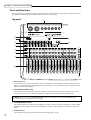
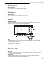
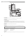
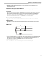
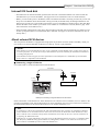
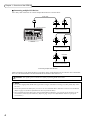
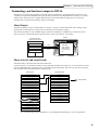
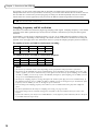
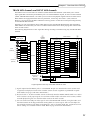
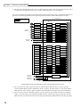

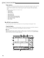
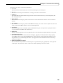
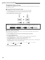
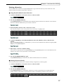
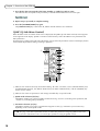
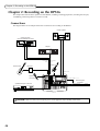
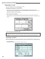
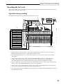
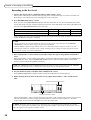
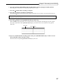

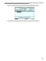
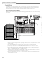
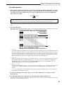
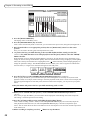
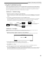
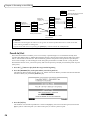
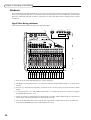
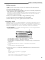
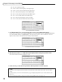
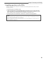
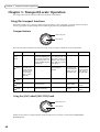
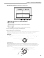
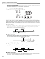
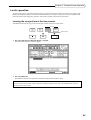
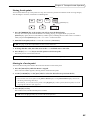
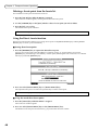
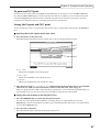
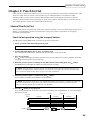
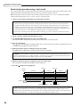
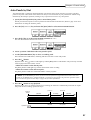
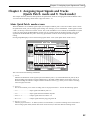
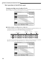
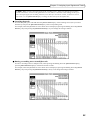
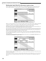
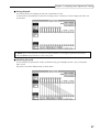
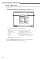
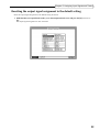
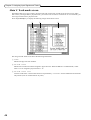
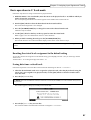
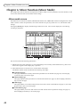
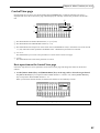
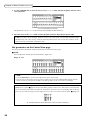
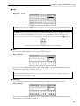
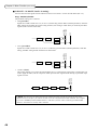
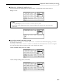
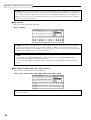
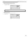

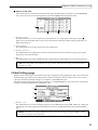
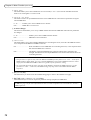
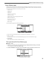

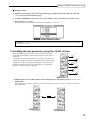
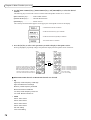
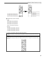
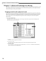
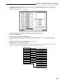
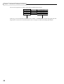
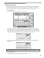
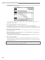
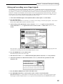
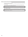
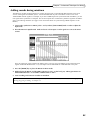
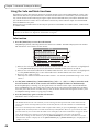
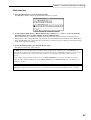
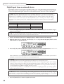
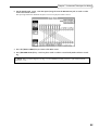
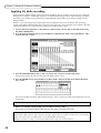
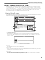
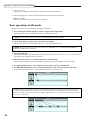

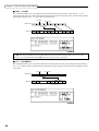
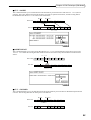
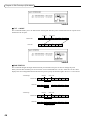
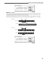
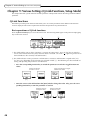
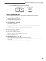

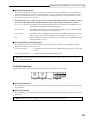
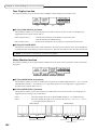
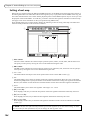
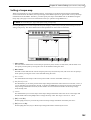
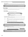
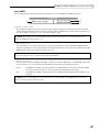
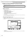
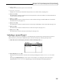
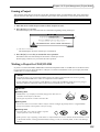
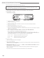
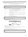
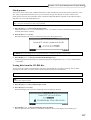
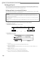
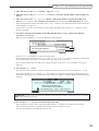
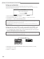
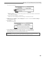
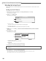
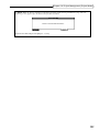
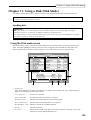
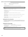
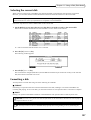
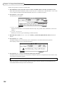
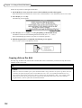
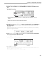
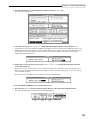
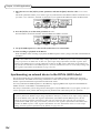
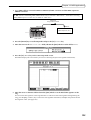
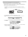
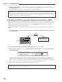
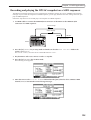
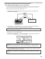
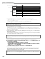
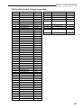
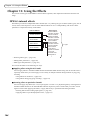
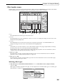


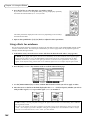
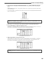
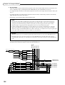
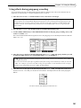
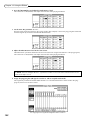

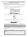
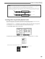
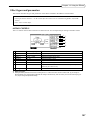
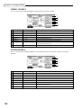
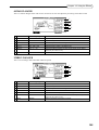
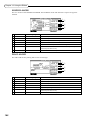
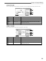
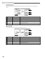
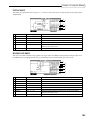
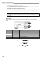
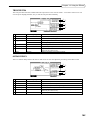
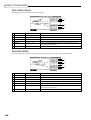
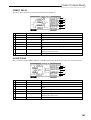
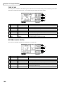
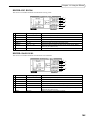
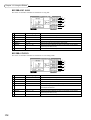
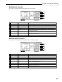
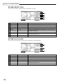

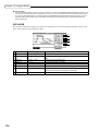
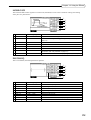
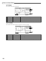
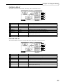
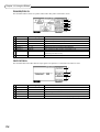
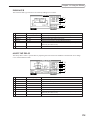
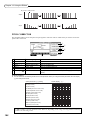
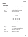
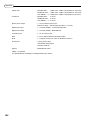
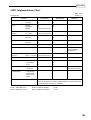
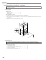
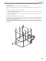


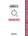
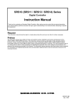
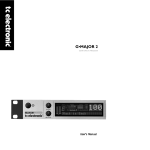
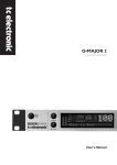

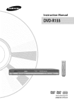
![SOLO [Nr.19] USER'S MANUAL](http://vs1.manualzilla.com/store/data/006880922_1-a650282ebddd9b1db13372fd9b60b3ef-150x150.png)