1
110-1097B
3/8/05
10:39 AM
Page 6
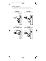
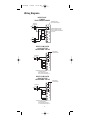
Wiring Diagrams
HEAT/COOL
5-WIRE
TWO TRANSFORMER
(HEATING)
Transformer
Hot
RH
120 VAC
24 VAC
RC
Heating
Control
W1
Cooling
Control
Y1
Fan
Relay
G
Hot
120 VAC
O
24 VAC
T
H
E
R
M
O
S
T
A
T
NOTE: Disconnect
factory installed jumper.
CAUTION: Both transformers
must be in phase or damage
to the equipment and thermostat
may result.
B
(COOLING)
Transformer
HEAT PUMP WITH
COOL ACTIVE
REVERSING VALVE
NOTE: Factory
Installed Jumper
RH
Transformer
Hot
RC
24 VAC
120 VAC
W1
Compressor
Contactor
Y1
Fan
Relay
G
Reversing
Valve
O
T
H
E
R
M
O
S
T
A
T
B
NOTE: Make sure the HP switch
is in the HP position.
When switched to HP mode,
W1 is connected internally to Y1.
HEAT PUMP WITH
HEAT ACTIVE
REVERSING VALVE
NOTE: Factory
Installed Jumper
RH
Transformer
Hot
120 VAC
RC
24 VAC
W1
Compressor
Contactor
Y1
Fan
Relay
G
O
Reversing
T
H
E
R
M
O
S
T
A
T
B
Valve
NOTE: Make sure the HP switch
is in the HP position
When switched to HP mode,
W1 is connected internally to Y1.
6