1
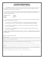
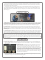
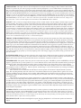
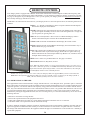
CONTENTS
INTRODUCTION......................................................................................................................3
MAINS CONNECTIONS..........................................................................................................4
CONNECTING YOUR STINGRAY..........................................................................................5
FRONT & BACK PANELS.......................................................................................................6
INPUTS, OUTPUTS, & THE STUFF ON THE SIDES........................................................7-8
DETAILED FRONT PANEL FUNCTIONS..............................................................................9
DISPLAY MODES...................................................................................................................10
OPTIMIZING YOUR SOUND SYSTEM..........................................................................11-12
TUBE F.A.Q........................................................................................................................13-14
ALL YOU NEED TO KNOW ABOUT BIAS....................................................................14-15
REMOTE CONTROL..............................................................................................................16
iPod & S-VIDEO, oMY!................................................................................................[also] 16
TROUBLESHOOTING...........................................................................................................17
CREDITS.................................................................................................................................18
SPECIFICATIONS..................................................................................................................19
FCC INSTRUCTION TO THE USER....................................................................................20
rev 4/19/11 CD
INTRODUCTION
THANK YOU!…
for choosing the Manley Stingray iTube integrated amplifier for your loudspeaker driving requirements. You possibly chose this product because you auditioned it in a store or heard it at a hifi show and were impressed with the
sound. It may have been the right combination of price, power, features and styling for you. It may have been because
you know the Manley Labs reputation for quality, reliability, and integrity. If any or all of these were the reasons, you
made a good choice and for that, we thank you.
The Stingray iTube is the next step up the ladder of evolution from our acclaimed Stingray Integrated Amplifier,
which has had a strong presence in the hifi industry since it swam from our labs in 1997. Originally designed with the
idea of “two monoblocks in one chassis”, the Stingray quickly became one of our best-selling products. Its passive
preamplifier delivers near absolute transparancy, no added noise, and extreme signal path simplicity. This preamp is
essentially coupled with a pair of 50 Watt monoblocks, which include custom-designed output transformers and an
“overkill” power supply that keeps immense amounts of energy stored so your system’s dynamic range and performance are never lacking. In addition to “beefing up” the power supply for the Stingray iTube, we have added digitally
controlled volume, balance, input switching, a headphone jack, and of course the iPod interface on top of the unit.
All added features are accessible via the front panel as well as with the included REMOTE CONTROL! We’re finally
catching up with the 21st century...or maybe just the 20th...
This product shares the same philosophies and standards of component quality and build technique as all of the recent
Manley products. It uses the best available parts with the shortest, cleanest signal path possible. Visually, this product
is unique, elegant, and practical. Visual beauty may be a prime factor for some but the size, shape and component
locations were chosen first for performance reasons.
Please take a few moments to read through this manual; there may be features and information about this unit which
you should familiarize yourself with.
Thank you again, and please enjoy!
GENERAL NOTES
LOCATION AND VENTILATION: The Stingray iTube should be installed on a stable location with ample ventilation to allow some cooling. A table top or cabinet top is a good choice. A speaker top is not the best location because
the vibration can transfer to the Stingray iTube and degrade the sound and possibly cause the tubes to become microphonic. If your household has small children, we suggest that the Stingray iTube be in a location where it may be
out of reach. Similar considerations should apply if you have pets. You do not want the cat or dog jumping up on it
or across it or possibly exposing them to hot tubes accidentally. This unit is meant for indoor use and should be kept
clean and dry. You will probably need occasional access to the sides and back so placing this unit inside a 3-sided
cabinet may be not practical. If the Stingray iTube is placed on top of other equipment, we suggest that rubber feet or
pads be placed under the Stingray iTube’s feet to prevent scratching the surface of the other gear. Pennies work just
fine for this too.
WATER & MOISTURE: As with any electrical equipment, this unit should not be used near water or moisture.
SERVICING: The user should not attempt to service the amplifier beyond that described in the owner’s manual.
Refer all servicing other than tube or fuse replacement to Manley Laboratories.
iPod is a trademark of Apple Inc., registered in the U.S. and other countries. Apple is not responsible for the operation
of this device or its compliance with safety and regulatory standards.
“Made for iPod” means that an electronic accessory has been designed to connect specifically to iPod and has been
certified by the developer to meet Apple performance standards.
3
MAINS CONNECTIONS
Your STINGRAY iTube has been factory set to the correct mains voltage for your country. The voltage setting is marked on the serial badge, located on the Right-Back of the unit, just above the Right-channel inputs.
Check that this complies with your local supply.
Export units for certain markets have a moulded mains plug fitted to comply with local requirements. If your
unit does not have a plug fitted, the coloured wires should be connected to the appropriate plug terminals in accordance with the following code:
GREEN/YELLOW
EARTH
BLUENEUTRAL
BROWNLIVE
As the colours of the wires in the mains lead may not correspond with the coloured marking identifying the
terminals in your plug, proceed as follows:
The wire which is coloured GREEN/YELLOW must be connected to the terminal in the plug which is
marked by the letter E or by the safety earth symbol or coloured GREEN or GREEN and YELLOW.
The wire which is coloured BLUE must be connected to the terminal in the plug which is marked by the
letter N or coloured BLACK.
The wire which is coloured BROWN must be connected to the terminal in the plug which is marked by
the letter L or coloured RED.
DO NOT CONNECT/SWITCH ON THE MAINS SUPPLY UNTIL ALL OTHER CONNECTIONS HAVE
BEEN MADE.
Waste Electrical and Electronic Equipment (WEEE)
Information for customers:
The European Parliament and the Council of the European Union have issued the Waste Electrical and Electronic Equipment Directive. The purpose of the Directive is the prevention of waste of electrical and electronic equipment, and to promote the reuse and recycling and other forms of recovery of such waste. As such
the Directive concerns producers, distributors and consumers.
The WEEE directive requires that both manufacturers and end-consumers dispose of electrical and electronic equipment and parts in an environmentally safe manner, and that equipment and waste are reused or recovered for their materials or energy. Electrical and electronic equipment and parts must not be disposed of with
normal household wastage; all electrical and electronic equipment and parts must be collected and disposed of separately.
Products and equipment which must be collected for reuse, recycling and other forms of recovery are marked with the following pictogram:
Small products may not always be marked with this pictogram in which case this is present in the instructions for use, on the guarantee certificate and printed on
the packaging.
When disposing of electrical and electronic equipment by use of the collection systems available in your country, you protect the environment, human health and
contribute to the prudent and rational use of natural resources. Collecting electrical and electronic equipment and waste prevents the potential contamination of
nature with the hazardous substances which may be present in electrical and electronic products and equipment.
Your MANLEY or LANGEVIN retailer will assist with and advise you of the correct method of disposal in your country.
4
Connecting Your Stingray iTube
Setting up this integrated amplifier is rather easy. Please refer to pages 8 & 9 for pictures of the back and sides of
the Stingray iTube.
1. You will be connecting power last and turning the system on after all other connections are made to prevent
ugly noises as wires are connected and to prevent possible damage to the amps and speakers. In general, it is
best to make any connections with the power off, the unit in “Standby” mode, or the volume control turned all
the way down. With all tube amps, you MUST have speakers (or a load box) properly connected to the speaker
terminals before power is turned on. Without a speaker, the voltage swings can be large enough to possibly cause
an electrical arc inside a tube, tube socket or transformer and this may damage the amp. Solid state amps operate
with no speaker connected but generally don’t tolerate a short circuit. Most tube amps will tolerate a short, but
we try to avoid this.
2. Before plugging in your interconnects, take a quick visual inspection of the tubes. Sometimes either through
shipping or unpacking things get jostled. Make sure all tubes are firmly in their sockets and standing straight up.
You might also verify that none have turned white inside. That indicates that air has leaked inside the tube (or the
vacuum leaked out!). Though it is rare, a tube is sometimes cracked or broken in shipping. It would need to be
replaced before powering up the amp.
3. On a rectangular chassis it is easy to specify front, back, sides etc - but on the 6 sided Stingray iTube we
should adopt a convention and refer to the sides that have the RCA inputs as Left-Back and Right-Back. We provide 3 left inputs on the Left-Back, 3 right inputs on the Right-Back, and an iPod interface on the top of the unit.
Plug in your interconnects, one at a time, from each source (i.e. CD, Tuner, AUX, etc.) then connect each input
to the appropriate RCA jack on the Stingray iTube. All RCA jacks are clearly labled as 1, 2, and 3. Each input is
for all intents functionally and electronically the same - only the labels are different. You may have to separate
or split interconnects an extra 12 inches if they are the “paired” type or slide the loop that holds the pair together.
If you need to connect a turntable (vinyl!) you will need a separate phono preamp to raise the level from the tiny
signal from the cartridge to regular line levels. Manley builds these, as do some other manufacturers. The final
interconnect available is the iPod interface, which will play your music from any iPod on the market at the date
of this manual’s publication.
5. Connect the speaker leads to the terminals on the far left and far right corners of the Stingray iTube. Be sure
that the RED (+) terminal is connected to the RED (+) wire and the WHITE (-) terminal connects to the WHITE
(-) wire. This color scheme may vary as to which color represents (-), but it is generally either black or white.
Connect the opposite ends to the speakers also RED to RED and WHITE to WHITE. This insures that your
speakers will be “in-phase”. All too often people accidently connect their speakers out-of-phase and lose most
of the lows. We have even seen this happen in “unthinkable” situations, most notably at hi-fi trade shows and
in record company executive offices. There is always some indication on the wire to help get “polarity” right
but it may be as subtle as a “ridge” on the insulation or different colored conductors. Most high quality speaker
interconnects are clearly labeled and/or color coded. Be sure that these connections are firm and solid. We do not
recommend using pliers or a wrench to tighten the terminals because one can easily overtighten or mar the finish
of the bolts. Good finger tightening is usually the best.
6. Before proceeding to the next step (power!) check that the On/Off switch on the back of the unit is in the
“Off” position. Now connect the IEC power cable to the back of the Stingray iTube and the other end to your
mains wall socket, or to your Power Supply Regulator if you have one.
7. Turn on the On/Off switch, and you will see a mini light-show on the front panel knobs. This will put the unit
into “Standby” mode. If you then press the “Standby” button (now glowing blue) on the front panel, it will initiate a 10-second warmup/mute period and the “Standby” button light will begin to pulse. You should be seeing
the tubes begin to glow a bit. None should turn bright red - that would indicate a problem. After 10 seconds, the
unit will power on completely and the front-panel LEDs will stop pulsing and remain lit.
5
8. To select one of the RCA inputs on the back of the unit or the iPod interface on the top of the unit, use the Input
Selection knob on the left side of the faceplate. The LEDs around the knob will tell you which input is selected. For
more information on this knob, see page 9.
9. To adjust the volume of your Stingray iTube, simply turn the Volume/Balance knob on the right side of the faceplate. To adjust the L/R balance, push this knob and hold it in for 2 seconds - then you are in Balance Mode. To exit
Balance Mode and return to Volume Mode, simply press and quickly release the knob. For more information on this
knob, see page 9.
FRONT PANEL
A) Input Selection & Menu Control: This knob displays and allows the selection of any one of the 4 inputs available on
your Stingray iTube. The LEDs show which input is selected, starting at the 9:00 position for Input 1 and ending at the
12:00 position for Input 4 (iPod interface). It also allows access to the Menu functions of the Stingray iTube, including
individual input gain adjustment and remote control modes. For more information on these functions, see page 9.
B) Standby Button: After powering on the unit via the switch on the back panel, this button will remain lit until the
Mute cycle has ended. At that point, pushing this button will turn on the Stingray iTube completely and allow audio to
pass through. To put the unit back into Standby Mode (no power to tubes, no audio signal passing through), simply push
this button again.
C) Volume & Balance Control: This knob displays and controls the volume of the Stingray iTube. Turning it clockwise
increases the volume, and counterclockwise decreases it. Push in the knob for 2 seconds and release it to enter Balance
Mode. To exit Balance Mode, push and quickly release the knob. For more information on these functions, see page 9.
NOTE: The two knobs on the front panel are known as “infinite rotary knobs”. This means they can rotate indefinitely
without ever encountering an “end” to their rotation. Rather than being a normal pot, the knob is actually a Grayhill
encoder that controls a Cirrus digital volume control chip. This chip changes the gain of the signal entering the tube
preamp section. As with the previous version of the Stingray, the Balance Mode reduces the gain of one channel at a time
to control the balance.
BACK PANEL
A) MAINS FUSE COVER: Pry the small slot to move the locking tab towards the fuse cover and it should pop open.
Only use an MDL 3 AMP / 250 Volt SLO-BLO fuse if it needs replacing (MDL 1.5 AMP / 250 Volt SLO-BLO for
220~240 units).
B) POWER SWITCH: Towards the fuse or away from the IEC power cable is
ON (I), towards the power cable is OFF (O). Make sure to power up your
sources first, to avoid any ugly noises from your speakers as your sources
come on. Now it’s Stingray iTube time! After you turn on this switch, the amp
will automatically go into Standby Mode. Press the blue Standby button on
the front panel, and the unit will Soft-Start (audio is muted), and will power
on fully after about 10 seconds. (When you are ready to turn your system off,
powering down should happen in reverse order from stated before - Stingray
iTube first, then everything else.)
C) IEC MAINS SOCKET: This is where the power cable goes. Note that your amp should be wired correctly for your
country. You may want to check the packing box to be sure. Also notice that this is a grounded 3-pin cable. If you get
a hum problem, see page 17 for some simple troubleshooting hints.
6
INPUTS, OUTPUTS, &
THE STUFF ON THE SIDES
INPUTS: Any of the three sets of stereo INPUT jacks can be used with any unbalanced RCA audio analog outputs
from your source components. They are electrically identical and only differ in the numbers screened onto the chassis. If you have balanced outputs on your source gear, check with the manufacturer on how to best interface them
with unbalanced loads. Most balanced gear can deal with unbalanced loads by use of XLR to RCA converter plugs or
special-made XLR to RCA cables. You’ll just need to check with each piece to see if it is best to ground Pin 3 or to
float it (not connect it). Transformer coupled outputs can always drive unbalanced inputs by hooking up the XLR Pins
1 & 3 grounded to the RCA shield, and XLR Pin 2 to the RCA center “hot” pin. If you have questions, check with the
manufacturer.
Separate from the first 3 Inputs, Input 4 is the iPod interface in the top of the chassis. Exercise care while inserting/removing your iPod, as the connector can be damaged if too much force is applied. If the iPod is removed, that
input will automatically mute itself, and will remain muted until you A) select a different input, or B) plug in an iPod.
REC OUT / LOOP SEND: Here at the REC OUT, whatever input is selected on the input select switch will appear
here. So you can plug this Recording output into a Tape Deck or CD Recorder or Computer Sound Card analog input
to make recordings from whatever is playing and selected on your input selector. Note that this is not a buffered output
so if your tape deck or recording device has a low input impedance, or if it does funny things like become a dead short
when it is powered off, like some IC inputs on certain CD recorders we do know of, you will load down the input to
the Stingray iTube (or short it out altogether and get no tunes!) Basically if you hear any difference or problems when
your recorder is plugged in, or if it is plugged in and powered off and sounding weird, then we suggest that you just
plug in when you are actually recording something. You can also use this output to drive another preamplifier in another room, for instance. Or if you wish to use another preamplifier instead of the one built into the Stingray iTube, you
can drive it here and run its outputs back into the Loop return. Another use of this Loop Send is to insert an equalizer,
or an external crossover to bi-amp. You would drive that external crossover here, and come back in to the Loop Return
after the crossover.
Note: The REC OUT output is always active. TO ACTIVATE THE LOOP RETURN - Press the “Insert” button on
your Remote Control.
...Please, Ladies & Gentlemen, continue on to the next page
for more information about the Stuff On The Sides...
7
LOOP RETURN: This input comes in after the Input Selector and just before the Stingray iTube’s Balance and Volume
controls. If you have all your sources going into another external preamplifier, or even a Home Theater surround processor,
then you could plug that preamp’s outputs here and let the Stingray iTube just function as a stereo power amplifier when the
Loop is active (see the previous page for more information). The Volume and Balance controls still function in this mode. The
REC OUT and LOOP RETURN function as an insert point or effects loop, meaning you can insert something like a crossover,
equalizer, or you can even monitor off your tape deck’s 3rd head using the INSERT button on your remote as a tape monitor.
*NOTE: If you are using Input 4 (iPod) and REMOVE your iPod, this input will automatically mute itself. If you are using the
LOOP RETURN for an extra source, that source will also be put into mute. To disable this inadvertent mute, simply select
any of the other 3 sources with the Input Select knob and the LOOP RETURN will be unmuted.
SUB OUT: This is a line level output after the Stingray iTube’s volume control. Use this output to feed the input of your subwoofer amplifier. The signal level of the output follows the main volume control in the Stingray iTube so that if you change
the volume control on the Stingray iTube, your external powered subwoofer amplifier will also track and change volume.
Remember this is a LINE LEVEL output, not a speaker output. If your subwoofer only has speaker level inputs on it, then
you need to drive it with the speaker outputs on the Stingray iTube. Use of the headphone jack mutes this output. *NOTE: Do
not use a Y-cable to connect a mono subwoofer to the subwoofer outputs. This will mono the main output from the amplifier.
Instead, just use a single channel to drive a single powered subwoofer input, or use the speaker level inputs off the Stingray
binding posts. Alternately, you could use an external Stereo to Mono combiner such as the RDL TX-LC2 Audio Combiner.
This would sum both Left and Right signals and provide a Mono balanced output to drive a powered subwoofer input. If you
need to drive an unbalanced input, use the (+) and Ground outputs.
TRIODE / ULTRALINEAR SWITCH: Located on top of the unit, just above the speaker posts. This switch changes the
configuration of the output tubes and how the screen grids drive the output transformer. Triode mode hooks the screen grids
up to the output tubes’ anodes and will give you around 20 watts. UltraLinear, also known as “Partial Triode”, connects the
screen grids to the UL taps on the output transformer’s primaries and will yield around 40 watts of output power. Triode mode
tends to give you a more etheral and delicate sound while the UL mode has a more aggressive or punchy sound. Feel free to
experiment and pick whatever operating mode you like the sound of best in your system. What will “sound best” really depends on your system and your room and your speakers and your tastes and what you are looking for. We do not suggest you
play with this switch all the time. You should never switch up and down rapidly as there are high voltages on this switch, and
you’ll blow something up quickly by nervously fidgeting with it. We strongly suggest you pick the setting you like best and
just leave it there.
B+ FUSE HOLDER: Should you need to replace this fuse, simply insert a flat-head screwdriver in the slot (after making sure
the unit is powered down completely, of course) and turn it counterclockwise. The fuse holder should pop out with the fuse.
Replace the old fuse with new one, push the holder back in, and turn the screwdriver clockwise to lock.
SPEAKER POSTS: The speaker connection posts are on the back side panels. The RED is positive and WHITE (or black) is
negative (ground). Be sure you have speakers (or a 4 to 10 ohm load resistor) connected to these terminals before powering on
the Stingray iTube. Tube amps (unlike solid state) require a speaker if there is any chance there will be a signal applied.
Watch out for reversing the positive and negative wires either at the amp or speakers (unless you want to simulate a record company executive’s office hi-fi). The lows get lost, and the image is very weird. If in doubt, try reversing one channel,
the way with the most bass is correct.
These terminals will accommodate most thicknesses of bare speaker wire and most U shaped terminals or banana
plugs. The only thing that they don’t like is thin wire. You should avoid thin wire for speaker cables in general. Use at least
18 gauge (18AWG) or heavier. Bigger wire has smaller AWG numbers. Be sure that the top bolts are tight, but avoid overtightening that might be difficult to undo or may damage the posts. In other words, firm as “strong finger tight” but less than
“big wrench tight”.
These outputs are appropriate for speakers rated between 3 and 10 ohms which includes all those 4 and 8 ohm speakers. For reference, the amp design and output transformers were optimized for 5 ohms. You’ll get a little less maximum power
on either side of 5, but don’t forget that your speaker manufacturer is giving you a nominal impedance figure when he tells
you that you have “an 8 ohm speaker” which means your speaker’s actual impedance swings wildly vs. frequency all over
the place. In real life, we have found 5 ohms to be a good place to be for most people. If you have some wacky speakers that
hit strange extremes, then you might be a good candidate to order some custom other-impedance output trannies from our inhouse magnetics department.
S-VIDEO OUTPUT: Located on the Left-Front panel. If a video (or photos) are being displayed on the iPod, they will also
output to this jack. Check your local RadioShack (or equivalent electronics store) for S-Video cables to help you get video
from the Stingray iTube to your TV or computer monitor. *NOTE: Certain newer generations of the iPod may not be able to
send video through this jack due to circuitry changes in the iPod itself. Generally speaking, any iPod produced before July of
2007 should be able to export video with no problems.
HEADPHONE JACK: Located on the Right-Front panel. Plugging headphones in will mute the speaker and subwoofer
8
output.
DETAILED FRONT PANEL FUNCTIONS
INPUT SELECTION KNOB: This knob, located on the left side of the faceplate, controls several functions.
Upon startup, it defaults to its basic function of changing the input on your Stingray iTube. The selected input is
visible according to which of 4 LEDs are lit on the knob itself. For example, seeing a lit LED at 9:00 on the knob
means that Input 1 is selected. Seeing an LED at 10:00 means Input 2 is selected, and so on and so forth. Input 4
(the 12:00 LED on the knob) refers to the Apple iPod interface on top of the unit. To change inputs, simply turn the
knob until the desired LED is lit.
In addition to selecting the input, this knob also controls the Main Menu functions of the Stingray iTube. To
enter the Main Menu, press and hold the Input Selection knob for about 2 seconds, then release it. The LEDs will
begin to pulse when you are in the Main Menu. To access each of the functions in this Menu, turn the knob, and
LEDs will follow the rotation of the knob. The Main Menu functions are as follows:
Main Menu Functions
1. DIM adjustment (9:00 LED lit): This is the first Menu function upon entering the Main Menu. On
the remote control, there is a button labeled “DIM”. When pressed, this button lowers the volume to a
predetermined level. This is useful when the phone rings, when someone comes to the door, or when
you think you can hear a neighbor saying something to the effect of, “If you don’t turn down that %$&#
music, I’ll...”. The DIM button is an excellent way for you to clearly hear your neighbor’s colorful language and intentions.
The control ranges from 0dB (no attenuation at all) to 23dB of attenuation. Your Stingray iTube
has been factory-set at 12dB of attenuation. To adjust the DIM level, just turn the Volume/Balance knob
on the right-hand side of the faceplate. Turning it fully counter-clockwise will give you 0dB attenuation,
meaning the volume will stay the same even if you press the DIM button. Turning the Volume/Balance
knob fully clockwise will give the maximum attenuation of 23dB. Each LED movement clockwise is
equal to +1dB of attenuation.
2. [no function at time of publication]
3. Input Level Adjust (11:00 LED lit): This menu option allows you to individually adjust the gain
of each input. This might be necessary if one of your sources is much louder or softer than the others.
Again, the Volume/Balance knob adjusts the gain in this mode. The range of gain adjustment runs from
-12dB in the fully counterclockwise LED position to +11dB fully clockwise. Default is unity (0dB adjustment), and that is signified by the 12:00 position LED on the Volume/Balance knob.
Before you enter the Main Menu, select the input whose gain you wish to change. When you
enter the Main Menu and select Menu Function 3, you will be adjusting the gain for that input.
Note: This gain change is controlled by the microprocesser than feeds the signal to the preamp.
It is not happening in the preamp itself, but rather just before the audio reaches the preamp. This means
that the REC OUT output level will not be affected by any changes you make in this menu mode.
4. Remote Control Configuration (12:00 LED lit): This Menu option allows you to change what type
of signal your Stingray iTube will accept from the included remote control. The default mode is both RF
(radio frequency) and IR (infrared) signals. Red LEDs on the Input Selection knob show which mode(s)
are active. The 2:00 LED signifies RF control, the 3:00 LED signifies IR control. If neither light is lit, all
remote functionality is disabled.To cycle through the modes, turn the Volume/Balance knob.
STANDBY BUTTON: When the unit is turned on, it defaults to Standby Mode. Pushing this button will then
bring it out of standby mode into regular operation. You can also use this button to RESTORE DEFAULT SETTINGS if you get lost in menus or just feel the need to reset your Stingray iTube to factory settings. To do this, just
turn off power to the unit with the back-panel power switch. Then, while pressing the STANDBY button, switch the
Stingray iTube back on again. Continue to hold the STANDBY button until all the front-panel lights have stopped
flashing and moving, and the unit will be restored to factory settings.
VOLUME/BALANCE KNOB: This knob, located on the right side of the faceplate, controls the volume and
balance of your Stingray iTube during normal operation. VOLUME MODE is the default on startup. Volume of the
unit is displayed with LEDs encircling the knob. More LEDs, more level. To enter BALANCE MODE, push and
hold the knob for 2 seconds, then release. Turning the knob clockwise decreases the volume of the left channel,
counterclockwise decreases the volume of the right channel. Each LED segment is equivalent to a 1dB change in
both Volume and Balance modes. Press and quickly release the knob to exit BALANCE MODE.
9
Display Menu Functions
The Display Menu is the second of the two Menus on the Stingray iTube. To access the Display Menu, press both
the Input Selection and Volume/Balance knobs at the same time. When all three red LEDs (Insert, RF, & IR) on the
Input Selection knob illuminate, release the knobs. The Insert LED will blink while in the Display Menu. To cycle
through the four options in the Display Menu, rotate the Input Selection knob. Pushing the Volume/Balance knob
while in each of these modes will toggle each mode ON/OFF; red LEDs at 2:00 & 3:00 on the Input Selection knob
will light up if the mode is ON. To exit the Display Menu at any time, press and release the Input Selection knob.
1) Display Timeout (9:00 LED lit): All LEDs turn off after the timeout period expires. Moving any
control or pressing any button (except the three iPod buttons) on the remote will turn the LEDs back on.
In this Display Menu selection, turning the Volume/Balance knob clockwise will increase the number
of seconds until the LEDs turn off; each LED around the border of the Volume/Balance knob signifies
approximately 1 second. Pressing the Volume/Balance knob toggles Display Timeout ON/OFF. Note: If
Starlight mode is enabled, the LEDs will twinkle instead of turning off after the timeout.
2) Display Dimming (10:00 LED lit): The maximum brightness of all blue LEDs is adjustable in 16
steps. At the lowest brightness levels, the unused blue LEDs that normally glow dimly will turn off completely. In this Display Menu selection, the number of lit LEDs around the Volume/Balance knob signify
the relative brightness of the blue LEDs. More lights (clockwise rotation of the knob) means brighter
LEDs. Factoy default is maximum brightness (16 on the LED scale). Pressing the Volume/Balance knob
enables/disables Display Dimming (disabled = no dimming = max brightness).
3) “Starlight” Mode Settings/Speed (11:00 LED lit): Only functional when “Display Timeout” is
selected. When the display times out, this mode will make the LEDs twinkle in a (mostly) random
sequence. In this Display Menu selection, the Volume/Balance knob controls the speed of the LED’s
twinkling. Clockwise means the LEDs will twinkle faster.
*In Starlight Mode, pressing the Volume/Balance knob allows you to cycle through its modes of
operation. The 2:00 & 3:00 red LEDs show how Starlight Mode will operate:
MODE
2:00 LED
3:00 LED
0 off offOFF
1
off
on
ON, brightness follows Display Dimming value & enable
2
on
off
ON, brightness follows Display Dimming value, ignores enable
3
on
on
ON, brightness is always MAX
4) “Starlight” Mode Density (12:00 LED lit): Only functional when Starlight Mode is ON. Turning the
Volume/Balance knob clockwise makes more LEDs twinkle in Starlight Mode, counterclockwise means
fewer LEDs will glow. Pressing the Volume/Balance knob turns the unused (dimmed) LEDs completely
OFF (while in this menu mode, lit 2:00 and 3:00 LEDs signify a complete “blackout” of unused LEDs).
This menu option allows you to fine-tune just how much light your Stingray iTube emits when in Starlight Mode.
None of the above functions operate while in the Display Menu, so you won’t see any changes until you exit the
menu. If you exit and then re-enter the Display Menu, the last function selected will still be selected. This makes it
easier to try different parameter values for a given function.
A NOTE ON THE MENU FUNCTIONS: The Stingray iTube saves your menu settings (volume, input selection, input gains, menu settings, display menu parameters and enables, etc),
but the actual act of saving the settings does not occur until the unit is put into Standby. This
means if you make changes within any of the menus and then immediately switch off the mains
(on the back panel), your changes will not be saved. To ensure that your settings are saved,
make sure to put the unit into Standby mode before turning it off completely.
10
OPTIMIZING YOUR SOUND SYSTEM
This section is full of little hints that may help you get the most out of your stereo - and it may not cost
anything or cost very little. Probably, you know most of this, but hopefully some of it may be new or refresh your
memory or just be refreshing reading in a manual.
A very important factor is your speakers. Hopefully you have good speakers and they are appropriate for this
integrated amplifier. What is appropriate? Well, with 50 watt of tube power per side and probably a limited budget
we would hope for reasonably efficient speakers so that the system will get loud enough for the music you listen
to. The “spec” to look for is “sensitivity” or “efficiency”. A speaker that is 95 dB efficient will easily get as loud
with these 50 watts as 85 db speakers with 150 watts. “85” will do if you only listen to folk or chamber music.
Usually you pay about the same for high sensitivity speakers but in amplifiers more watts is more $. By the way,
many reviewers confirm that 50 tube watts is similar to 100 solid state watts. If you are buying speakers, it is wisest to carefully listen to them before buying. You will most likely like them longer if they tend to sound natural and
real rather than over-emphasized in some area. In other words, think “accurate reproduction”, not “numbers” and
“hype”.
The price of speakers is often directly related to the low frequency response. Great lows generally require
deep pockets and plenty of power. Thanks to “home theatre” there are a lot of powered subwoofers available that
won’t drain your resources. Get one that connects to speaker outputs (or the SUB OUT RCA jacks on your Stingray
iTube) so that it follows your input selection and volume control. This makes connecting them pretty easy.
There are some very interesting speaker tricks. Most people just place them wherever it is convenient. Spouse
approval is a real factor. We suggest that you experiment with speaker placement, then when they sound 100%
better you bring in the spouse and demonstrate the difference. They should be able to hear the improvement and
may totally agree with your choice. You should aim for equal distances between your listening position to each
speaker and from speaker to speaker. The ideal is an “equilateral triangle”. Try to get the speakers off the floor,
and away from the walls (both side and back). The angle of the tweeter or speaker front panel to your face is also
critical and experiment with that too. You should be getting a smooth frequency response so that highs and lows are
balanced and mids not too prominent or distant. It should simply sound “natural”. When we buy color TVs the first
thing most of us relate to is flesh tones because it is something we all relate to and know when they are right. The
equivalent thing in audio is vocal tone. We have evolved amazing discrimination for the varieties of human voice
and much less for other instruments. Use a few well recorded CDs with vocals and adjust the speakers to get the
most natural voices. If you are lucky, you will end up with a system that creates a 3D picture of the music that not
only has left/right width but a solid distinct center. It should also make some sounds seem in front of the speakers
and some behind. We have heard some systems with great components even give an illusion of the height of the
individual musicians. Most rooms are longer in one dimension. Some systems sound best with the speakers across
the short dimension and the listening position part way back but not right at the back wall. Some systems are better
across the long dimension. The only way to find out is to try.
If you are getting this amazing imaging and soundstage, you may be interested to know why you suddenly
have it now that you have the Stingray iTube. These are very audible effects that seem to be beyond normal measurement technique or textbook electronic theory. This effect is directly related to the amount of negative feedback
used in a design. The less feedback the greater the imaging. In transistor amplifiers it has been common practice
to use more than 80 dB of negative feedback. Conventional designs need it because transistors are not particularly
linear devices and it forces the circuit to get low distortion figures as well as very high damping factors. Tubes are
much more linear and inherently low distortion. Tube amplifier designs use far less negative feedback (less than
20 dB) as a result . We speculate that the negative feedback may have a negative effect on transient accuracy. It is
reasonably documented that the feedback does reduce the lower order harmonics in distortion but can raise higher
order harmonics that are more audible. Feedback also makes the transition from clean to clipping very abrupt and
abundant with high order harmonics. The best audio devices always seem to be simple & aesthetically balanced,
with form following function.
11
You may have bought a great system but there is a good chance that you are only getting a fraction of its potential. Very frequently we have experienced top quality electronics sounding unimpressive simply because acoustics were ignored. Even amongst studio engineers, few can really tell the difference between good speakers in a
bad room and bad speakers in a good room - but they all know good speakers in a good room and very likely so do
you. Acoustic techniques are better explained in books on recording studio construction. You can buy good readymade acoustical materials and/or build them yourself for a fraction of the cost. Dollar for dollar, you can expect far
greater improvement with acoustic treatment than expensive interconnects.
Most people think acoustics is about sound-proofing but there is a lot of info available for improving the
reproduction of music. Sound-proofing is usually expensive. Luckily just improving the acoustics in a room can be
pretty painless. You may be able to change or move what is on the floors and walls (without getting expensive or
ugly). The improvements may be dramatic.
Number One on the bad list is parallel surfaces. That pretty much includes most rooms. Parallel surfaces can
support a very short echo that is known as a standing wave. It boosts some frequencies and cuts others. This effect
is often called comb filtering because of the multitude of peaks and dips. One cure is breaking up the big surfaces
with a variety of smaller ones. The good news is that book shelves, curtains, wall hangings or macrame, plants, furniture and lamps all help. Not only does this balance live surfaces with dead ones but “checker-boarded” areas also
act as a sort of diffuser. You can probably build low cost effective and attractive diffusers or have them made if you
want something better (and more efficient).
Number Two is very unbalanced room treatment. Both too “live” and too “dead” is generally bad. One might
think that wall to wall carpets & curtains is going to be fine but watch out. All that stuff only eats highs and a little
mids, but doesn’t do anything to the lows. The lows end up very live in contrast to very dead highs. One way to
balance this is get some thick absorbsion into the corners. Thick absorbsion in the corners is most effective to
lows. The idea is to balance high and low absorbsion. Even normal speech sounds weird in near empty rooms with
plain painted gypsum walls and hardwood floors. The simpler the decor the more intense the acoustic problems.
The only hints we can offer is that the wall behind the speakers and behind you are often the most important. You
can build some simple absorbers. Simply cut two 4’X8’ pieces of 2” rigid fiberglass or open cell foam rubber into
16”X8’ strips and wrap some white cloth around them. Easy, clean looking and cheap. Experiment, lean them
against the wall at various places. Even very experienced acoustic designers experiment, listen then decide rather
than attempting to predict every result. A variation is to use “perf-board” as a backing if you intend to stretch the
fabric reasonably tight. It may also help with hanging the strips to the walls. Perfboard with a one or two inch space
behind it is an alternative front surface to increase diffusion or can do double duty as a simple helmholtz absorber
(for the low mids) and can be effective on the ceiling. You can hang a few up there either flush or dropped a few
feet if you have the height to absorb lower frequencies. The wall behind the listening position is usually responsible
for too much or too little lows compared with the rest of the room. Read up on slat and membrane absorbers for
problems there - the panels described above won’t help much for that.
Number Three is lack of left/right symetry. In order to get the left and right similar sounding and getting a
rock-solid center you should have identical left and right walls and distances. The ideal is a perfectly symmetrical room but this may not be practical. Again, try to achieve this with positioning. Some of the “test” CDs have
a variety of low frequency tones or sweeps. Use them to find rattles and buzzes in the room. Lamps and fixtures,
some cabinets and components can do this. A little tape or glue can often fix these types of things. If you are getting
serious about this kind of thing you can get a variety of test gear from measurement mics to real time analysers or
computer software. These are useful tools but do not depend on the readings unless you are very experienced using
them. Best to use your ears and use the test gear to verify what you hear and to document the changes. Remember
that test gear neither makes records nor listens to music. Frequency measurement often ignores “time”, and exagerates some factors while glossing over others. Steady tones are virtually useless in real rooms. The more comprehensive tests give complex data that needs to be correctly interpreted to be useful. Use ‘em but don’t jump to conclusions. Always use ears too.
12
TUBE F.A.Q.
A few general all-too-frequently-asked vacuum tube questions from the manleylabs.com F.A.Q. as found on
our website are answered here in case you don’t have internet access (which we don’t doubt because after all
you bought vacuum tube amplifiers, didn’t you?):
(Don’t take that comment personally. EveAnna still drives air-cooled Volkswagons...)
FAQ #16. Do you sell tubes?
I don’t know what you’re talking about.
FAQ #16a. I need to retube my Manley amplifier. Do you sell tubes?
Sorry. Just kidding. Yes, of course we do. We have about 100,000 tubes in stock of the several major types we use.
FAQ #16b. Why should I buy tubes from you?
We are only as good as our worst tube. We are very selective about which tubes we use in Manley products and we
have several different testing and burn-in jigs to test for certain parameters which will be most important for that
tube in a given circuit. We will test and select a tube set for you that will be optimized for your Manley piece of
gear and in most cases, your tube set will actually be tested in another one of what you have.
FAQ #16c. Are tubes expensive?
Not especially. Although I might have made a killing in the stock market had I invested the money, I instead put
it into finding and stocking these large quantities of tubes twenty years ago when the USA military was dumping
its stocks of NOS JAN vacuum tubes. Seriously, there is the stocking cost to consider in the cost we must charge,
development charge of the computerized test jigs we built, then more importantly the time it takes one of our guys
to run a little tube through its qualification procedures. Remember, a given tube cannot be improved during testing.
It is the way it is, and one hopes it stays that way. It can only be selected, and in selecting that tube that will work
really well for your piece of gear, we probably had to throw away several. In some cases we might have had to go
through 30 tubes to find the quietest one, or the one with the lowest microphonics, or the one with the best internal
matching, depending on what parameters are important for that circuit. That is all factored into the cost somewhat,
but no, overall, we don’t charge enough for replacement tubes.
FAQ #16d. NOS? JAN? What does that mean?
New Old Stock. Joint Army Navy. Yes, our military used to use vacuum tubes. As long as the glass doesn’t break,
tubes are impervious to a nuclear explosion’s electromagnetic pulse unlike little silicon devices whose little junctions would go poof!
FAQ #16e. Good to know. How long do tubes last?
Some of them are dead out of the box. Some tubes don’t make it through burn-in and after a few days they just go
noisy or quit. Sometimes UPS sabotages our shipments and after all our testing efforts the tube arrives broken at
your place. Sometimes a tube decides to end it all early and intentionally misbehaves after a few months. Other
tubes are real troopers (like my 98 year old neighbor) and run strong for 30 years. We have documented cases of
power tubes in Manley amplifiers going over 60,000 hours non-stop in recording studios 24/7/365 without a retube. In one case in particular, the amplifiers were never turned off and had their own dedicated air conditioning for
the amplifier rack they lived in. This certainly contributed to their long life.
FAQ #16f. Should I turn off my gear between uses?
While power cycling is a factor for ultimate tube life, there also is a fixed number of electrons that can ultimately
jump off the cathode. In general we do recommend if you aren’t using the gear for more than a few hours you
should power it down, or in the case of your Stingray iTube just put it in “Standby” mode with the little blue button
on the front panel.
13
FAQ #16g. But it sounds different when you first turn it back on. What is the warm-up time for this gear?
We generally recommend 45 minutes warm-up time for everything to reach operating temperatures and sound like
it’s supposed to. It will reach “listenable” temperature, however, in just a few minutes.
FAQ #16h. What about break-in time for new gear? We burn in the gear for a couple of days before it is shipped
out. Folks report that after about a week of break-in that it sounds better. Some of the more fussy people of course
report that full break-in takes much longer....
FAQ #16i. How do I know a tube is broken? All the vacuum has leaked out.
FAQ #16i.i After the vacuum leaks out, where does it go? Is there some way to collect it and put it in another
tube, to make it last longer? You have to suck really hard.
FAQ #16j. No really, how do I know a tube is broken? Usually a tube whose glass has been broken or cracked
usually will have a white powdery like substance inside it where all that silvery stuff used to be. No, it is not cocaine and we didn’t put it there..
FAQ #16k. Does the glass explode? I haven’t seen it happen. Usually the glass will just crack at the base of the
tube if it is going to physically break due to a sudden change in temperature and “all the vacuum will leak out”.
FAQ #16l. Other than outright failure of a tube, how do I know when it is time to re-tube? Generally speaking, for the small tubes, if you notice an unacceptable increase in background noise (“hiss”) then the tube who is responsible for making the gain in the circuit probably needs to be replaced. The tube(s) making the gain will usually
be shorter than the output tube. Common types we use for gain in most of our circuits will be 12AT7, 6201, 12AU7,
5814, 12AX7, 5751, or 6072. The output buffer tube in most of our line-level circuits will be either the 7044, 6414,
or 12BH7. These tubes usually don’t cause too much trouble and either work or don’t work. Turn the lights off and
see if you see the little tubes glowing. Look for one that looks like it has cocaine in it.
For the power tubes in our amplifiers, after a few years if you notice a small revolt going on where several of the
output tubes are misbehaving or getting hard to bias, you might consider doing a full re-tube. Keep the old ones that
did not join the revolution as emergency spares.
FAQ #16m. Can I change a tube myself? R.T.F.M....do you call in specialists to change your light bulbs for you?
See page 5 for details on how to accomplish this task.
ALL YOU NEED TO KNOW ABOUT BIAS...
What do I need to know about BIAS? Bias is a simple DC (negative) voltage that sets, what is called, the “operating point” of the tube. For our purposes it “fine tunes” the current going through the tube. We want each of the 4
tubes per channel to be equally sharing the load. This gives the amplifier’s lowest distortion and the tube’s optimum
life. When we set “bias” we are adjusting that voltage and measuring the current at a pin called the cathode. The
cathode is connected with a 10 ohm 3 watt resistor that allows the more convenient voltage measurements from terminals right on the top panel. These 10 ohm resistors also have a second job. They are fuses in case of a really nasty
tube failure. Sometimes a tube will die in a way that burns up this resistor (with a little puff of smoke) and then with
a new tube you will only measure zero at the terminal for that tube. The resistor should be replaced by a technician,
but it should only take ten minutes. Can you solder?
How often should I check these BIAS points? Some people never do. It really should be done when you change
a tube and it is very likely that a little adjustment will be needed. We suggest that you check every 3 months - that
way you are assured that the amp is running optimally and will spot a tube on its way out. Some check every
month, once a week is getting a little obsessive.
What tools do I need? Just two. A small flat screwdriver (insulated handle) to adjust the trimmers. You also need a
voltmeter or multi-meter, one of which we’ve provided with your new Stingray iTube. How convenient! Any multimeter will do; it doesn’t have to be a good one. RadioShack sells them as well, if you want to purchase a different
one for some reason. As long as it measures DC volts between 0.1 (100mV) and 1 volt, you’ll be just fine.
14
What do I do? The amp should be well warmed up (30 min.) and no music playing. Set the meter to read DC
volts. The meter has two test leads, red and black. Put the black lead in the black terminal on the top marked TPG
(ground) or touch the metal point to the steel chassis (but not a painted or anodized part). Put the red lead in the
first red terminal marked TP1. The meter should read either .25 V or 250 mV(same thing). If it doesn’t you need to
adjust BIAS 1 trimmer until it does. It doesn’t need to be exact - .23 to .27 will do. Now move the red lead to the
red test point labelled TP2. Same thing, if it is not .25 adjust BIAS 2 so that its close. Continue till all 8 points have
been done. If you trimmed a few, you should re-check because there is a little interaction and you may want to fine
tune a bit.
What if the reading is drifting up and down? Some drift is normal. It is caused by the AC mains changing and by
a little very low frequency noise in the tube. If one drifts above .3 or below .2 then you may be seeing a tube begin
to go bad. Watch it for a while or check it every few weeks noting changes. This tube should be replaced probably.
With mains changes all the tubes drift together and you may see more long term drift. Another cause is that you
forgot to stop the music.
What if I can’t trim a tube into range? If all you get is zero or near zero on one terminal it means either the tube
or 10 ohm resistor is dead and needs replacing. If it is too high then it probably is the tube. If you look at the tubes,
that one will probably be cherry red. Get a new tube. If all the terminals read zero on one channel, then the B+ fuse
is likely blown on that side. If all the terminals read zero on both channels but the amp still plays, then you have a
problem with the meter.
Are there any advantages to biasing higher or lower than 250mV? This is the optimum trade-off between tube
life and cross-over distortion. If you bias a little higher you may lower distortion a bit but shorten tube life a lot. If
you bias lower the distortion climbs fast and the tube life will lengthen - partially because you won’t want to listen
as often or as long.
15
REMOTE CONTROL
Your Stingray iTube is equipped with a Remote Control that communicates with the amplifier via RF (radio frequency) and/
or IR (infrared) signals. In the Stingray iTube’s Menu Mode, you can alter these transmission settings (to learn how to do that,
see page 9). RF signals can pass through walls, so now you can operate your Stingray iTube from Anywhere In Your House!!
We’re finally catching up with the last century.
This Remote can control almost all functions of your Stingray iTube. As seen in the picture below, the following functions are
available:
Inputs: 1, 2, 3, & iPod. On the Stingray iTube’s faceplate, LEDs around the Input Selection knob display the selected Insert.
Standby: Pushing the top-center button puts the unit into Standby mode, and wakes it
up if pressed again. In Standby mode, no audio comes through the unit - no high voltages are present, no glowing tubes, etc.
Mute: Be Gone, Beautiful Music! Thou art Silenced! While the Stingray iTube is
muted, a blue LED will pulse at 6:00 on the Volume/Balance knob.
Volume: LEDs around the Volume/Balance knob display the current volume.
Balance: LEDs around the Volume/Balance knob display the current balance only in
Balance Mode. See page 9 for details.
Insert: This switches the Loop Return On or Off (the REC OUT output is always active). When this button is pressed, the Stingray iTube looks for signal at the Loop
Return rather than at the selected input. When Loop Return is on, an LED at 1:00 on
the Input Selection knob glows red.
DIM: Lowers volume to a predetermined level. See page 9 for details.
iPod Controls: Previous, Play/Pause, & Next
Note: When the Stingray iTube is recieving signal from the remote (every time one of
the remote’s buttons is pressed), a red LED will momentarily illuminate at 2:00 on the
Input Selection knob. If the Stingray iTube’s remote has dead batteries, this red light
will NOT flash, and the remote will NOT function.
Another note: To pair a “universal” remote with your Stingray iTube, the supplied Manley remote control must ALREADY have been paired to the Stingray iTube. For reference, the IR “carrier” frequency for the Stingray iTube is
38kHz, which is standard for many universal remote controls.
FCC INSTRUCTION TO THE USER
This equipment has been tested and found to comply with the limits for a class B digital device, pursuant to part 15 of the FCC
Rules. These limits are designed to provide reasonable protection against harmful interference in a residential installation. This
equipment generates, uses and can radiate radio frequency energy and if not installed and used in accordance with the instructions, may cause harmful interference to radio communications. However, there is no guarantee that interference will not occur
in a particular installation. If this equipment does cause harmful interference to radio or television reception, which can be
determined by turning the equipment off and on, the user is encouraged to try to correct the interference by one or more of the
following measures:
* Reorient or relocate the receiving antenna.
* Increase the separation between the equipment and receiver.
* Connect the equipment into an outlet on a circuit different from that to which the receiver is connected.
* Consult the dealer or an experienced radio/TV technician for help.
In order to maintain compliance with FCC regulations, shielded cables must be used with this equipment. Operation with nonapproved equipment or unshielded cables is likely to result in interference to radio and TV reception. The user is cautioned
that changes and modifications made to the equipment without the approval of manufacturer could void the user’s authority to
operate this equipment.
16
REMOTE CONTROL (cont’d)
Setting the SLEEP TIMER Function
(Serial # MIST086 and higher)
We’d like to think that the sonic attributes of our Stingray iTube are exciting and immersive enough to prevent you from ever
falling asleep while listening, but we do understand that occasionally such circumstances arise. Perhaps your iTube is the center of your home entertainment system and you want to fall asleep while watching a movie, or perhaps you are in the habit of
lulling yourself to sleep with the soothing sounds of birds, city street noise, rain, or Metallica before bedtime....in that case, this
option is for you.
The Remote Control must be used to access the Sleep Timer menu. Using the remote:
1. Press and hold the STANDBY button to access the Sleep Timer menu.
2. Press the MUTE button: once to set for 15 minutes, again for 30, 45, and 60 minutes. Pressing it again will turn the timer off.
3. Release the STANDBY button. The Sleep Timer has now been enabled for the chosen setting, and the menu exits.
The LED display around the Stingray iTube’s VOLUME control knob will show “minutes” chosen:
1/4 LEDs lit = 15 min
1/2 LEDs lit = 30 min
3/4 LEDs lit = 45 min
ALL LEDs lit = 60 min
Once the Sleep Timer is enabled and running, you can watch “time remaining” before the unit falls asleep (or at least until you
do) when “Display Timeout” mode is active (see page 10 for details on how to turn this mode on). The LEDs at the volume
control knob will start turning off as time moves towards 0 minutes. When time is up, the volume will fade out slowly, then the
unit will go into Standby. Sweet dreams, iTube.
iPod & S-Video, oMy!
First, a thought from Manley Laboratories: The integration of an iPod interface into a high-end tube audio system may seem
strange to some of our customers. What do we think? Given the vast storage capacity of the newest generations of portable
digital music players (like the iPod), CD-quality music (and better, perhaps) can be easily stored on such devices. The addition
of the ubiquitous iPod to our newest high-end integrated amplifier simply makes it easier for people who carry around an iPod
with them everywhere to enjoy their music through an audiophile-quality home system. With the proliferation of inexpensive
iPod-compatible stereos on the market, why not bring that convenience to the upper eschelon of home audio?
Aside from audio, many new generations of iPod have video storage capabilities. We designed the Stingray iTube to take full
advantage of this, and thus have included an S-Video output on the Left-Front panel of the unit. Using this output, you can
now view pictures or videos stored on your iPod on a larger screen and still hear the audio in full All-Tube Glory from your
Stingray iTube! Most electronics stores carry S-Video cables (and adaptors if neccessary) to help you get the video from your
Stingray iTube to your TV or computer screen. *NOTE: Certain newer generations of the iPod may not be able to send video
through this jack due to circuitry differences in the iPod itself. Generally speaking, any iPod produced before July of 2007
should be able to export video with no problems.
17
TROUBLESHOOTING
It is rare that any of these problems occur, but here are some things to try if something is “wrong”:
HUM - Try a mains ground adapter if they are legal in your country. They are also called 3 pin to 2 pin adapters (or
“cheaters”) and are available in hardware stores. There should be one ground in your system and only one. If two or
more pieces of gear have 3 pin AC cables a ground loop can occur which will usually cause hum. The Stingray iTube
is probably the best grounded single piece as it is the center of your system.
HISS - Usually one of the sources. This source may have a volume control that is turned down and forcing you to turn
up the volume of the Stingray iTube. Adjust the source so that it is a similar volume as your other sources. If it seems
to be the one channel of the Stingray iTube, then it is probably an input tube (12AT7WA). Most tubes should last
many years but sometimes they get noisy prematurely. To verify, you can swap the two 12AT7s (with the power off)
then test again. Be careful - tubes can be hot (let them cool down for a few minutes or wear a glove), don’t bend any
pins and gently wiggle the tube to remove it or insert it. Force should not be needed.
BALANCE - The two speakers sound different - It may be the CD or source and the way it was recorded. First try a
different source. Next try swapping the inputs. Power down and swap left and right inputs. If it is the source, then the
problem will “follow” the swap. Return them to normal (L=L). Power down again and next try swapping the speaker
connections by putting the left speaker wire in the right terminals and right wires into the left terminals. If the problem
switched sides then the Stingray iTube is suspect, if the problem stayed on the same side it is probably a damaged or
fatigued speaker.
ONE CHANNEL DEAD - Usually just a bad connection or an interconnect is plugged in wrong. Check your wiring.
You can try any of the other inputs and verify that both channels work on other inputs or not. The Balance Control
is adjusted for “center”? You might try swapping the speaker interconnects at the Stingray iTube end. If the problem
swaps sides then it may be the Stingray iTube. In that case, the two most likely problems are a bad tube (12AT7 or
6414) or a blown 250 mA (MDL 1/4) B+ fuse accessible through the sides of the unit. See page 8 for details on changing this fuse.
TUBE GLOWS CHERRY RED - This is where you can see the plate area of the tube glowing red hot (they are normally gray or black and are the most visible part inside the tube). This indicates a bias problem or a bad tube; immediately attempt to re-bias the tube in question (see page 15). If the bias cannot be adjusted on that tube, immediatley turn
off the power; the tube will have to be replaced. It is normal to see a slight blue glow that seems to coat the inside of
the glass.
REMOTE DOESN’T FUNCTION - Dead batteries? Try aiming the remote directly at your Stingray iTube. If you
press any button on the remote, a red LED should light up at the 2:00 position on the Input Selection knob. If the LED
does not illuminate, try changing the batteries. If that doesn’t fix it, make sure the Stingray iTube is set to recieve
signal from the remote - see “Remote Control Configuration” on page 9 of this manual to learn how to configure your
remote control.
To “pair” your remote control with your Stingray iTube: First, turn off the main power switch on the
rear of your Stingray iTube. Then, while pressing the front-panel volume knob IN, switch the main
power ON. When the lights stop spinning on the front panel, release the volume knob and press any button on the remote control. Your remote is now “mated” with your Stingray iTube!
NO SOUND FROM INPUT 4 (iPod) - Is your iPod plugged in correctly and firmly seated on its connector? If the
Stingray iTube doesn’t think an iPod is plugged in, it will not be able to play tunes from it. Try removing it and replacing it on the connector - be careful, the connector is delicate and can be damaged if abused!
NO SOUND AT ALL - Is the unit in Standby? Is the unit Muted? Is the INSERT loop active (1:00 LED glowing red
on the Input Selection knob) with no signal coming in to the LOOP RETURN? This will mute the Stingray iTube, as it
will not hear anything coming back from the REC OUT output (see pages 7 & 8 for more info).
Feel like you’ve inadvertently set up a Menu function incorrectly? Can’t figure out how to undo it? See page 9 for
instructions on RESTORING YOUR STINGRAY iTUBE TO FACTORY DEFAULT SETTINGS.
18
CREDITS
An EveAnna Manley Production
Directed by: Humberto Rodriguez
Mastered by: Baltazar Hernandez
Titled by: J. Gordon Holt
Fancy Lights/Coding/Anti-Spam Assistant: Advice/Helpful Hints/Sushi Companion:
Remote Control Abuser/Field Tester/Production Staller:
Manual Labor/Stunts: Jerry Garszva
Mitch Margolis
Ryan Kato
Chris Dauray
- The Legend of The Stingray It all began at the HI-FI ‘97 show. We find the protagonists of this tale seated comfortably at the bar,
of course - J. Gordon Holt with his traditional martini, and EveAnna Manley with her stimulant of choice,
a cup of coffee. She was describing a new integrated amplifier she wanted to build, and proceeded to
make one of those legendary “bar-napkin drawings”. Gordon remarked, “It looks like a stingray [the fish,
not the car]...” and thus, in honor of Gordon, we called this little jobbie “The Stingray”.
Now, in 2008, we have revisited that time-tested design and made a few improvements. In keeping
with current societal trends, we’ve also managed to get our paws on the trademark for “iTube” and are
now quite pleased to be able to use it. As a company building predominently vacuum-tube equipment, we
are never one to be behind the times. Thank you for supporting Manley Laboratories, and we truly hope
the Stingray iTube brings you as much enjoyment as possible. Thanks again.
19
SPECIFICATIONS
- 4 x Stereo Line RCA Inputs
- TRIODE - UL Switching
- RECORDING OUT
- SUBWOOFER OUT
- TAPE LOOP (Insert) with Bypass switch
- Logic controlled Volume and Balance functions
- All-Vacuum Tube Lo-feedback Stereo Integrated Design
- Output Tubes: 8 x EL84 - Ships with Russian NOS EL84M (aka 6Pi14Pi-EB)
- Driver Tubes: 2 x 6414 - Ships with GE or RAYTHEON JAN NOS USA or 6414W
- Input Tubes: 2 x 12AT7EH - Ships with: 12AT7EH large plate Electro-Harmonix Russian
- Maximum Output Power UL mode: 32 Watts x 2 channels 1.5% THD @ 1kHz into 5 ohms
- Maximum Output Power TRIODE mode: 18 Watts x 2 channels 1.5% THD @ 1kHz into 5 ohms
- Frequency Response: 15 Hz - 58 kHz, -1dB
- Gain: 35 dB at max Volume
- Volume Control Range: 102 dB (1dB per step when turned slowly)
- Input Sensitivity UL Full Power: 210 mV in = 32 watts out into 5 ohms with volume control at maximum
- Input Sensitivity Triode: 41mV in = 1W into 5 ohms with volume control at 20dB gain setting
- Input Sensitivity UL: 35mV in = 1W into 5 ohms with volume control at 20dB gain setting
- S/N Ratio: typically 72 dB A-WGT, 20Hz-20KHz, 1W output, 20dB gain, Source Z = shorted input
- THD+N Ratio: typically 64 db at 1W output, Bandwidth 22Hz-22Khz, Source = 1Khz Sine wave
- Input Impedance: 12 Kohm nominal
- Optimum Speaker Load: 5 ohms
- Actual Output Impedance at 20Hz: 2.36 ohms
at 1KHz: 2 ohms
at 20KHz: 1.83 ohms
- Output Z (Headphone Output): 53 ohms
- Damping Factor: 2.4
- Scratch Factor: Use pennies under pointed feet to avoid marring cabinetry. Try quarters if you are in upper tax brackets.
The bargain performer would be nickels. Paper currency does not function as well. Euro coins work
1.54 times better.
- Remote Control Type: RF (radio frequency) and IR (infrared), user selectable (IR carrier frequency: 38kHz)
- Volume Control: Cirrus Digital Level Control System, controlled by Grayhill Rotary Encoders
- Power Consumption (Standby, no iPod charging): 6W
- Power Consumption (Standby, iPod charging): 12W
- Power Consumption Idle: 198W
- Maximum Power Consumption at Full Power: 300W
- MAINS Fuses:
100~120VAC operation: MDL 3 AMP / 250 Volt SLO-BLO
220~240VAC operation: MDL 1.5 AMP / 250 Volt SLO-BLO
- B+ FUSES (2):
MDA 1/4 AMP, 250 Volt SLO-BLO, Ceramic. (Located internally)
***Only use SLO-BLO (time delay) 1 1/4” x 1/4” 3AG fuses***
- Power Supply: is factory set for 100V, 120V or 220-240VAC operation for original destination country’s mains voltage.
- Operating Mains Voltage: changeable with power transformer re-wiring on PCB and fuse value change.
- Mains Voltage Frequency: 50~ 60Hz
- Power Cord: Detachable IEC standard.
- Appropriate power cord supplied for original destination country
- Dimensions: W= 19”, D=14”, H= 7 1/2”
- Shipping Weight: 35 lbs.
20