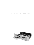
1
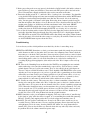
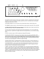
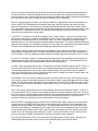
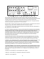
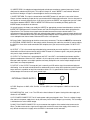
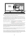
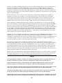
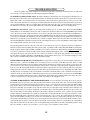
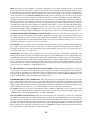
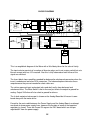
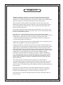
MANLEY
LABORATORIES, INC.
OWNER'S MANUAL
The WAVE by MANLEY
MANLEY LABORATORIES, INC
13880 MAGNOLIA AVE.
CHINO, CA. 91710
TEL: (909) 627-4256
FAX: (909) 628-2482
emanley@ manleylabs.com
http://www.manleylabs.com
CONTENTS
SECTION
PAGE
INTRODUCTION
3
OPERATION NOTES
4
CONNECTING YOUR WAVE
5, 6
THE FRONT PANEL
7, 8
THE BACK PANEL
9, 10
THE EXTERNAL POWER SUPPLY
10
THE REMOTE CONTROL
11
A FEW NOTES
11
THE GUTS, TRIMS, SWITCHES, ETC
12, 13
CREDITS
13
SPECIFICATIONS
14
TROUBLE SHOOTING
15, 16
MAINS CONNECTIONS
17
BLOCK DIAGRAM
18
APPENDIX - WIRING CABLES
19
WARRANTY
20
WARRANTY REGISTRATION
21
INTRODUCTION
THANK YOU!...
for choosing The WAVE by MANLEY. Please read over this manual carefully as it contains
information essential to proper operation of this unit.
The WAVE by MANLEY is a unique product combining a high end Digital to Analog
Converter with an audiophile vacuum tube preamp and remote control. It is one of the very few
products equally at home in a professional Mastering facility for producing CDs as it is in a
superb home listening system matched with great amps and speakers. The combination of
features and functions came about from analyzing existing systems and finding them functional
but lacking in elegance in signal flow, operational convenience and synergy. We set out to
build something we wanted in our own living rooms, something that could be upgraded as new
standards evolved and something that could meet the needs of mixed balanced, unbalanced and
digital connections.
The initial digital board is designed around the ULTRAANALOG chip set (including the
AES-21 jitter removal and Pacific Microsonics HDCD decoder) proven over the years to
provide the most satisfying and enjoyable reproduction.While it is certainly holding its own
with CDs as 24/96 chips continue to be intoduced we have made provisions and plans to offer a
24/96 board so that future music delivery formats can be fully appreciated.
The WAVE accepts 4 digital inputs and 4 analog inputs as standard. The digital inputs
accomodate most of the current interconnect standards. The Analog inputs allow both balanced
and unbalanced interconnects. Normally it ships with 2 balanced and 2 unbalanced inputs but
the factory can custom configure a unit for special requirements (such as 4 balanced inputs)
In recognition of real life needs, extra input/output facilities are standard. For those who
record, or have need of external processing we include an Insert loop (the term borrowed from
pro audio) similar to a Tape Loop or processing loop. There is also provision for more than one
set of amplifiers/speakers with 3 outputs (2 can be switched, 1 is always on).
We packaged all this in a visually attractive box, gave it a external power supply and a
full function remote control and we didn't stop there. The tube analog section is a new design
and was developed to out-perform our previous benchmark both audibly and in specifications.
LOCATION & VENTILATION
The MANLEY DIGITAL TO ANALOGUE CONVERTER must be installed in a stable
location with ample ventilation.
WATER & MOISTURE
As with any electrical equipment, this unit should not be used near water or moisture.
If liquid enters the unit, it must be immediately returned to your dealer for servicing.
SERVICING
The user should not attempt to service this unit beyond that described in the owner's manual.
Refer all servicing to Manley Laboratories.
3
OPERATIONAL NOTES
SWITCHING ON
All cables should be pre- connected to the WAVE especially the EXTERNAL POWER
SUPPLY cable and interconnects to the power amps and the AC mains.
The power switch is located on the back panel of the EXTERNAL POWER SUPPLY. You
shouldn't need to turn the supply around or get yourself behind it. You should be able to "feel"
the rocker switch located next to the AC power cord. Flip the switch away from the power cord
to turn on the Wave or towards the power cord to turn off the unit.
RUNNING
It is not recommended that you leave your Wave stay permanently switched on. This only
wastes electricity and tube life. We provide a STANDBY switch which effectively turns the
Wave off. The Wave reaches peak operating condition in approximately 15 minutes.
TUBE LIFE
As with all tubes, their quality degrades with age. This is due to cathode emission, a natural
process found in all tubes. We recommend that you have your preamplifier checked every 4-5
years, depending on usage. An excessive increase in noise level can indicate the need to replace
a tube.
REPLACING A TUBE, INDICATOR LAMP or FUSE. You should read page 10 for more
details if you need more specific info. You may need a small Phillips screwdriver and the
correct replacement fuse, tube or lamp. First be sure the unit is off and remove the IEC mains
cable. Let it sit for 15 minutes to be sure all power supply capacitors are discharged otherwise
one could still get a shock even though the unit is unplugged. If you are changing a tube or
lamp, be sure that it the same number or is on the list of possible substutions. Gently wiggle the
tube around while pulling it out of the socket. Avoid bending the printed circuit board. Before
putting a new tube in, look at it. Check to see that the pins are straight and that they line up to
the socket. You should be able to gently push the tube into the socket without excessive force.
Changing these tubes should be a rare event and should be accompanied by a re-calibration.
4
CONNECTING YOUR WAVE
Setting up the Wave is rather easy. Please refer to page 9 for a diagram of the back of the
Wave.
1. You will be connecting power last and turning the system on after all other connections are made to prevent ugly noises as wires are connected and to prevent possible
damage to the amps and speakers. In general, it is best to make any connections
with the power amps turned down or off, Wave power off and the volume control
turned all the way down. Do not ever apply mains power to the power supply
without it first being attached to the main WAVE unit. DO NOT "HOT-PLUG" !
2. Before plugging in your interconnects first connect the Wave to its external power
supply. Verify the rocker switch on the back of the External supply is in the "0"
position which indicates OFF (1=on) and that the supply has not been powered up
in the last 1/2 hour (capacitors need time to discharge). Before we go further, keep
in mind the idea of an external power supply is to keep radiated hum far from audio
components so mounting the supply directly under or over the Wave tends to defeat
the purpose. The big cable coming out of the back of the Wave has a round 16 pin
connector that mates with a matching socket on the back of the external supply.
Line up the "flats" on the plug & socket, the plug should slide in easily, and a few
turns clockwise of the ring will lock it in.
3. On the back of the Wave connect your power amps ( or next processor) to the Wave
Outputs. For simple systems, use OUTPUT 1, L&R which are the 3rd connectors
from the left, looking at the Wave from the back. Then, feel free to connect any
analog sources, ie tuner, phono preamp, VCR, etc to the 4 stereo analog inputs
marked ANALOG 1 through ANALOG 4. The "standard" Wave has 2 pairs of
RCA phono jacks typical of most consumer hi-fi and 2 pairs of XLR jacks typical
of hi-end balanced components and pro gear. Adapters or special cables can be used
that allow one to use the XLRs with RCA phono type sources. See appendix 1 for
the details if needed. Tape recorders (with analog inputs & outputs) for intention of
recording with (or external processors) should be plugged into INSERT. This
allows recording any of the 8 inputs without a worry of a feedback howl.
4. Connect digital sources with the appropriate interconnects to the Wave digital inputs
furthest to the right. There is also a digital output which is the selected source
before any de-jitter or re-clocking. NOTE, that there is a possibility of a feedback
oscillation if the recording machine is selected on the Wave front panel while in
record or the deck is in the "monitor input" or "REC & Pause" mode. This is a
situation where the digital recorder is attempting to record itself at unity gain and
oscillation is the result.
note) Panasonic DAT decks are notorious for only accepting pure consumer mode in
its S/PDIF inputs and may not "see" some sources. This is also the case if you
connected directly. The DAT's AES/EBU inputs may be a better choice.
5
5. Before proceeding to the next step (power!) check that the On/Off switch is Off and the volume is
turned all the way down (anti-clockwise). Now connect the IEC power cable to the back of the
Wave's External Power Supply and then the other end to your mains wall socket.
6. Turn on the On/Off switch (to "1") and let the Wave "warm-up" for a few minutes. You should be
seeing the blue LEDs light up and some more noticably bright than others and the MUTE button
should have started out bright and probably went dim after 20 seconds - this is the warm-up
delay. You may push a few buttons at this point. Notice that when a button is pushed it toggles
from dim to bright to dim (bright = selected). Because the Wave when first turned on may be in a
random status, perhaps we should start off with some buttons in the "dim" mode. PHASE,
INSERT and MUTE should be dim. (If one of the 4 digital sources is selected and it is not
sending data, then the WAVE will automatically MUTE - try selecting A 1 to verify this)
7) Let us start off checking with a favorite CD. First select the input that you have chosen for the CD
preferably digital but analog should work. Press Play on the CD. If it is a digital input, then the
44.1 LED will be on and the Wave MUTE LED will be dim. Slowly turn up the Volume Control
and enjoy the music. Next check the other sources to verify they all work fine. From here on out,
use the STANDBY button to power down the Wave.
Troubleshooting:
It is rare that any of these initial problems occur but if they do here is some things to try.
SILENCE in ONE SIDE. Sometimes we don't get an interconnect pushed in enough for good contact
and it disconnects while we plug other wires in or move the component. Power down, check the
interconnects, re-check the above procedure. Power up and try again. If you have sound, sit back
and enjoy. If not, you may want to temporaily swap some interconnects to verify that you a) have
sound coming out the source, b) each of the interconnects is verified to be working fine, c)
everything IS plugged into appropriate jacks and/or each of the Wave's inputs seems to accept
signal.
HUM - First try the Grounding Posts on the back of the WAVE by un-strapping the two terminals
and/or connecting a wire fom either terminal to the suspect device. You can also try a mains
ground adapter if they are legal in your country. They are also called 3 pin to 2 pin adapters or
"cheaters" and are available in hardware stores. There should be ONE GROUND in your system
and only one. If two or more pieces of gear have 3 pin AC cables a ground loop can occur which
will usually cause hum. Today's power amps typically have 3 pin AC mains cables, so it is easy
to see where beween 2 power amps and the Wave, where one could have 3 grounds (at least)
connected both via interconnects and AC mains cables and that is two too many.
HISS - Usually one of the sources. This source may have a volume control that is turned down and
forcing you to turn up the volume of the Wave. Adjust the source so that it is a similar volume as
your other sources. If it seems to be the one channel of the Wave, then it is probably an input tube
(5751). Most tubes should last many years but sometimes they get noisy prematurely. To verify,
you can swap the two 5751's (with the power off) then test again. Be careful - tubes can be hot,
don't bend any pins and gently wiggle the tube to remove it or insert it. Force should not be
needed. If it wasn't a 5751, then put them back into the original locations.
NOISES. Sometimes a tube gets microphonic in shipping. This may result in a bit of "metallic ring"
in the signal or "ping" when the chassis is tapped, or even something that sounds like sputtering
RF noise. Usually gently tapping on the tube reveals the culpret and sometimes cures it.
BALANCE - The two speakers sound different - It may be the CD or source and the way it was
recorded. First try a different source. Next try swapping the inputs. Power down and swap left
and right inputs. If it is the source, then the problem will "follow" the swap. Return them to
normal (L=L). You can check all the way down the chain this way and really isolate and verify
the problem. Was it the volume control on a power amp?
6
D E F
S
H
A
1
2
IF
D
A
D
C
SP
K
HD
K1
48
ND
G
A
MM
3
2
T
3
E
T
STAN
T
MU
RT
E
OU
INS
4
T
A
S
BY
OU
WAVE
MANLEY
S
S
A
THE
TT
OO
C
O
SE
A
AE
PH
K
44
32
ABC
BY
D
HANDCRAFTED WITH PRIDE IN CHINO, CALIFORNIA USA
ULTRAANALOG™ DAC REMOTE CONTROLLED ALL-TUBE PREAMPLIFIER COMBO
I
J
K
L
M
All the buttons and LEDs are blue and the name "The Wave" came from a comment that the lit front panel
looked like an ocean wave breaking. The buttons glow dimly to assist in darkened rooms, and only glow
brightly when that function is selected.
A) INFRARED SENSOR. This is the reciever for the infrared remote control. It doesn't light up ever.
B) COMMAND. Indicator to show a valid command from the remote control or front panel. Push any button.
C) SAMPLING RATE INDICATORS. Light up to show the incoming digital signal's sample rate and will not
light until the anti-jitter circuitry has locked onto valid data.
D) Phase. Reverses the polarity of the Digital Converter when pushed and lit. This can be a subtle effect
however because it is performed in the digital domain does not degrade fidelity. It has no effect on analog
inputs.
E) HDCD. Lit when the source is HDCD encoded and is being HDCD decoded.
F) DIGITAL INPUT SELECT. Pushing one of these 4 buttons selects from either the AES/EBU, S/PDIF,
Toslink or ST (glass fiber) Inputs to the Digital to Analog Converter and S/PDIF digital output. The last button
pushed (of these 4) stays lit even if one of the 4 ANALOG INPUT SELECT buttons is pushed to indicate
which source is still feeding the digital output. This feature allows one to use an external DAC which could
return into any of the analog inputs, and allows easy digital recording.
G) ANALOG INPUT SELECT. Pushing one of these 4 buttons selects from the 4 stereo analog inputs. In
conjunction with the DIGITAL INPUT SELECT, the last pushed of these 8 buttons, is what is being heard.
H) VOLUME CONTROL. I guess we don't really have to explain what this does but we can tell you it is a
custom-made precision 4 gang conductive plastic motorized Noble pot. It requires 2 gangs per channel
because the signal is balanced right into the tube line amplifier.
I) INSERT. If you what a TAPE LOOP or PROCESSING LOOP is, then you know what this button does. It
allows an external device like a tape machine or Equalizer to be used with the selected source and breaks
into the normal signal flow right before the Volume Control with the INSERT RETURN to monitor that path.
"INSERT" is a word borrowed from professional audio. With nothing patched into the loop, when the button is
pushed, the signal is cut off. If this is annoying, just use a simple short interconnect to patch the INSERT
SEND to the INSERT RETURN.
7
note 1) The insert send and return can be factory wired for either balanced or unbalanced loops. Balanced
Inserts use XLR 3 pin connectors appropriate for pro reel to reel tape decks and pro EQs (like the Manley
Massive Passive). For a nominal charge we can also provide sensible tape monitor switching and input/output
for 2 tape decks and EQ (but we expect very few will need this level of complexity).
note 2) On special request, the factory can modify the INSERT for appropriate surround sound decoders so
that the INSERT RETURN bypasses the Volume Control and Tube Line Amplifier and comes back right
before the Output Select. This assumes the surround sound decoder becomes the master volume control.
This arrangement allows the high quality DAC and selected analog inputs to feed the surround sound decoder
and retains the 5.1 calibrated levels while also allowing multiple outputs and an integrated way to quickly
return to a true audiophile two channel mode.
J) OUTPUT 2. The Wave has 3 final stereo outputs. Unless muted, Output 1 is always on and there are no
relays in this signal path as is common for audiophile systems. Output 2 and Output 3 can be turned on and
off separately. The standard WAVE is set up so that either 2 or 3 is on and pushing either button toggles
between these two. This allows alternative amplifier/speaker combinations. This is often needed by mastering
engineers (they typically use a few different speakers to verify quality and compatibility) and reviewers for A/B
testing as well as audiophiles with dedicated headphone systems and surround set-ups.
note) There are internal jumpers that change this arrangement so that Output 2 and Output 3 can be used
independently. An application for this is multiple room systems where the Wave feeds amps and speakers in
several locations. This also disables the remote control Phase button which then becomes OUTPUT 2 select.
K) OUTPUT 3. As above. Output 3 is a balanced floating output and is fully compatible to drive balanced or
unbalanced inputs and is the best choice when long lines need to be driven. Pin 1 (Shield/Ground) may be
disconnected in situations where ground loops and hum tend to be a problem.
L) MUTE. Simply silences the Wave when lit. The Wave has two other conditions that force MUTE. There is a
20 second time delay MUTE when the Wave is first powered up to prevent the big thumps typical as tubes
reach operating temperature (it also mutes quickly on power-down). The second "force mute" condition is
when one of the digital inputs is initially selected and when there is no data (or the data is invalid). Again, this
is to prevent un-controlled glitches and digital noise.
M) STANDBY. This is a "barely on" mode that turns off the power to the DAC, relays, LEDs & tubes and just
uses a trickle of power to allow the front panel to remember its settings, respond to buttons and to the remote
control. The Standby indicator should be dim and all other LEDs will be off. When STANDBY is pushed again,
all the LEDs return to the last used setting, except the MUTE which is in "force mute" for 20 seconds as the
tubes warm up.
note) There may be a short learning curve involved between the various combinations of MUTE, OUTPUT 2/
3, Insert and INPUT SELECT where it seems annoying that you have to push buttons to get music. If you are
like us, the cause is a bit of impatience while waiting for the warm-up delay and pushing buttons which end up
killing the signal and causing confusion when it was only muted during the warm-up. If you wait the 20
seconds the Wave will return to the last used setting before it was put in Standby.
When the Wave is unplugged or power turned off at the external power supply, settings are lost and it tends
to power up with the PHASE, MUTE and OUT 3 selected but no source selected. There is no default initial
setting so this may be random (including INSERT). You will probably need to push the PHASE, MUTE and
select one of the 8 INPUTs. Depending on your system OUT 2 may have to be toggled as well. The settings
are not retained with a battery, and the logic is discrete rather than employing a micro-controller to prevent
another source of clocked logic noise entering the system. You just have to look at what is lit after you first
turn it on, but using STANDBY will be painless if you have 20 seconds worth of patience.
Very rarely the digital input reciever may lock-up when switching between various sources. Switching to a
different digital input and back usually cures this and STANDBY totally resets the DAC board.
8
LEFT
The WAVE
by MANLEY
DAC / Preamp
SERIAL NUMBER
AN EVEANNA MANLEY PRODUCTION
RIGHT
LINE STAGE DESIGNED BY C. HUTCHISON
PCB'S & CHASSIS BY B. HERNANDEZ
LOGIC DESIGNED BY J. GARSZVA
MANLEY LABORATORIES
13880 MAGNOLIA AVE., CHINO, CA 91710
PHONE (909) 627-4256 FAX (909) 628-2482
email: [email protected]
DIGITAL I/0
OUTPUT 3
OUTPUT 2
BALANCED
OUTPUT 1
UNSWITCHED
INSERT
RETURN
INSERT
SEND
ANALOG 2
ANALOG 1
GROUND
CIRCUIT
CAUTION - RISK OF ELECTRIC
SHOCK. DO NOT OPEN.
REFER SERVICING TO QUALIFIED
PERSONNEL ONLY
TO REDUCE THE RISK OF
ELECTRIC SHOCK DO NOT EXPOSE
THIS EQUIPMENT TO RAIN OR
MOISTURE
O
ANALOG 3
XLR INPUTS AND OUTPUTS
PIN 1 = SHIELD = GROUND
PIN 2 = HOT = POSITIVE PHASE
PIN 3 = LOW = NEGATIVE PHASE
POWER SUPPLY
P
ANALOG 4
N ML
K
J
I
CHASSIS
H
G F
SELECTED
DIGITAL
OUTPUT
E
ST
D
TOSLINK
C
S/PDIF
B
AES / EBU
A
note) This panel is the standard layout for the WAVE, however, Manley Labs does custom configure
individual units to order with alternative connectors and different variations of balanced and unbalanced inputs
and outputs. While the drawing may not accurately depict your jacks, the locations should be valid.
A) AES/EBU DIGITAL INPUT. Connect the appropriate balanced digital input here. The digital interconnect
should be a proper digital cable optimised for 110 ohm termination.
B) S/PDIF INPUT. As above, but the consumer version, unbalanced 75 ohm. Very popular but this interface is
designed for shorter cables. Both the AES/EBU and S/PDIF are transformer coupled.
C) TOSLINK INPUT. Another popular standard interconnect and uses plastic optical fiber. Unfortunately it is
best avoided unless no other option exists.
D) ST INPUT. Generally the best choice as it uses a premium glass fiber that provides the widest bandwidth,
fast square waves and electrical isolation. Unfortunately, many players do not include this because the cost of
interfaces and cable is higher. This standard was created by AT&T and adopted for digital audio. The
ULTRAANALOG AES-21 digital reciever module offers exceptional jitter rejection but we can often hear an
improvement comparing ST to AES or S/PDIF cables. These bayonette style connectors require a quarter
turn clockwise to lock. They can be fragile so some degree of gentleness is best when connecting /
disconnecting or moving the converter.
E) SELECTED DIGITAL OUTPUT. S/PDIF output follows the last selected digital input even if one of the
Analog Inputs has been selected for listening. This allows recording and digital dubs. The front panel LEDs
indicate the last digital source. Panasonic DATS may or may not be capable of dealing with this output.
F) ANALOG 1. The standard Wave provides 2 stereo unbalanced RCA inputs (compatable with most hi-fi and
consumer equipment) and 2 balanced XLR stereo inputs (compatable with some premium audiophile
equipment and pro gear). These are not phono inputs (which require way more gain, different impedances,
and RIAA deemphasis) but the output from a phono preamp, FM receiver, tape deck or VCR, etc should be
connected here (or ANALOG 2, 3 or 4) and this input is selected with the A 1 button.
G) GROUND TERMINALS. These 'ground posts' are intended to help in some installations particularly where
a special audio grounding scheme is used. The top post is the audio circuit ground and the bottom is chassis
and AC third pin ground. For almost all applications these posts are connected together with a strap or solid
piece of wire. If you are getting hums and buzzes, this is a good place to sart experimenting, and why we
include them.
H) ANALOG 2. Just like ANALOG 1 and corresponds to the A 2 button
I) ANALOG 3. Just like ANALOG 1 except typically a balanced XLR connector.
J) ANALOG 4. Just like ANALOG 3.
9
K) INSERT SEND. An unbalanced output designed to feed tape recorders or external processors. Usually
configured as unbalanced RCA jacks. This output is always on, even if INSERT is not selected. Whatever
input of the 4 Analog or 4 Digital is selected appears here as an analog signal.
L) INSERT RETURN. This input is selected when the INSERT button is lit and then is sent to the Volume
Control. It allows monitoring a tape deck as you record and A/B comparison/verification. You can also patch in
an Equalizer or external processor here. If you have no use for the INSERT, we suggest that you use a short
interconnect between INSERT SEND & INSERT RETURN so that if somebody accidently pushes the
INSERT button, that audio is not silenced.
On special request, the factory can modify the INSERT for appropriate surround sound decoders so that the
INSERT RETURN bypasses the Volume Control and Tube Line Amplifier and comes back right before the
Output Select. This assumes the surround sound decoder becomes the master volume control. This
arrangement allows the high quality DAC and selected analog inputs to feed the surround sound decoder and
retains the 5.1 calibrated levels while also allowing multiple outputs and an integrated way to quickly return to
a true audiophile two channel mode. Balanced XLR Insert is also possible.
M) Power Cable. Captive design to minimise unnecessary connectors. The other end MUST be connected to
the EXTERNAL POWER SUPPLY. We strongly advise connecting this cable first, then the AC mains cable at
the SUPPLY. Once all the audio connections are complete, then you can turn on the power. DO NOT HOTPLUG !
N) OUTPUT 1. This is the normal output intended to be connected to your main amplifiers. It is automatically
muted while the Wave's tubes warm up and if the MUTE button is lit, however signal is not passing through a
relay and is simply shorted to ground to MUTE.
O) OUTPUT 2. The Wave has 3 stereo outputs and OUT 2 and OUT 3 are intended for alternate amplifier /
speaker combinations. When the OUT 2 button is lit, this output can send to an amplifier or headphone amp.
Most pro audio engineers use multiple speakers and many audiophiles can use the multple outputs to feed
other rooms or to compare products.
P) OUTPUT 3. Like OUTPUT 2 except this jack is normally an XLR and the signal is transformer balanced
and floating. It can be used to feed balanced or unbalanced inputs on amps and is particularly useful if ground
loops and hum is a problem or long lines need to be driven. Pin 1 is ground which can be cut for a true
isolated output which tends to cure some ground loops.
EXTERNAL POWER SUPPLY
10
ABC
D
A) FUSE. Requires a 2 AMP, 250V, Slo-Blo, 1/4" fuse (MDL2) for 120V operation. 1AMP for 220-240 Volt
countries.
B) POWER SWITCH. 0=off, 1=on. The LED on the front indicates AC power is being fed to the supply and
remains lit in STANDBY.
C) IEC POWER CONNECTOR. The AC mains power cable gets plugged in here. There is a voltage changeover switch in the power supply that is set by the factory for the mains voltage in your country. The set voltage
is indicated on the serial number badge.
D) MULTI-PIN POWER CONNECTOR. 16 pin connector that supplies all the needed volts/currents to the
Wave. The Wave also sends a signal to the supply that turns on the most of the supply, which means it is
truly difficult to measure the supply unless the Wave is connected via this connector.
10
The Remote Control
PHASE OP2/OP3
The remote provides essentially all the
buttons found on the Wave front panel
plus 2 buttons for Volume. The Wave
front panel has a big knob for volume
and a motor behind it. The remote
uses two buttons to slowly and
smoothly increase or decrease the
volume. No VCAs, no MDACs.
You can see a LED on the remote
blink when you push any of the
buttons and on the Wave front panel
the COMMAND LED also indicates it
has received the command. These are
just "confidence" or "verification"
indicators. You can also watch the
WAVE simply respond to your
commands as every function does
show its status on the front panel.
STANDBY
AES
A1
MUTE
SPDIF
A2
INSERT
TOS
A3
VOL UP
ST
A4
VOL DN
There is a way to make the Remote
the "only" control and disable the
Wave front panel button commands if
for example you have kids not allowed
to "play" with the system. One just
puts the remote in a safe place. The
following page shows DIP switch
locations to do this. Changing any of
the DIP switches in the REMOTE will
have the opposite effect. Changing all
3 sets of DIPS is helpful when you
seem to have two remotes that clash.
All functions are labelled the same
and operate the same as on the front
panel. The only possible exception
would be due to a special modification
that changes the function of the
PHASE and OP2/OP3 buttons.
Jumpers inside the Wave can be set
up so that OP2 is toggled by the
PHASE button, which means the only
way to change phase is via the front
panel. When this mod is done, OP2/
OP3 only toggles OP3. This is only
the case if the jumpers are changed
and normally the remote is sent out
with the button labels indicating
exactly what the buttons do.
The Remote Control uses 3 common
AA 1.5 volt batteries. The circuit is
designed to maximise battery life
while providing enough optical power
to control the WAVE from a few
hundred feet. Batteries will probably
last a few years.
A Few Notes
There is a few things which don't really fit anywhere else in the manual;
There is no "Empasis" Indicator or LED. The HDCD chip automatically takes care of this in the digital domain
and we chose not to provide a LED for that only because it would almost never glow (so few CDs ever used
that function) and it was always intended to be an invisible, inaudible function.
There is no 88.2, 96 or other sampling rate indicators other than the 32, 44.1 and 48. 88.2 and 44.1 share the
same LED, 96 and 48K share the same LED. Commercial CDs only come in 44.1, so you should see that
LED most of the time. The initial Ultra-Analog DAC board can not deal with those high sample rates.
There is no MONO button. There is also no Phase Reverse function for "just one side only" or the analog
inputs, no DIM button and individual muting of each side. For Mastering engineers and possibly a few
audiophiles this is something we could add as an option and probably not something we could remote control.
We have a maximum of 15 buttons and it is not trivial to mod a 4 layer board.
There are no high voltages on the multi-pin connector until it is mated and the supply is told to turn on. This
makes it particularly safe. However, if it has been on, the mate disconnected and the capacitors have not yet
discharged (it takes about 5 minutes to discharge connected and 15 minutes disconnected) then if somebody
were to touch those pins, they might get a 300VDC shock - non lethal, but very startling and possibly giving
pin-prick burns. Not something for children to play with. The household AC sockets are far more dangerous.
Poking wires, pins etc through the cooling slots is also a bad idea with any electrical/electronic gear.
11
HDCD
GAIN
DIGITAL to
ANALOG
CONVERTER
INPUT
SELECTION
PASSIVE
ANTIALIAS
FILTERS
INSERT
OUTPUT
SELECTION
(& MUTE)
7044
7044
12AX7
12AX7
LEFT
RIGHT
REGULATORS
& WARM-UP
DELAY
LEFT GAIN
TRIM
DIP2
1
2
3 4
RIGHT GAIN
TRIM
DIP1
J1,J2
J3
The gains of the Wave are set at the factory. There are only 4 trimmers (2 per channel) but because the input to
the line amplifier is balanced and it is a minimum feedback design, it requires a trimmer for each phase or leg. So both
trimmers affect the gain and the "balance" of the two trimmers affect common mode rejection. Yes, this could have been
made more convenient, but it would have compromised some sonic performance.
The method to adjust these requires an oscillator, AC voltmeter, CD test disk with 1K digital full scale and a
special banana to XLR M cable that allows the oscillator to send between: a) pin 1 & pin 2, b) pin 1 & pin 3, c) pin 2 &
pin 3 (normal balanced) and d) between pin1 & pin2+pin3 (for CMRR). These tests are done with the Volume control
turned up full, the appropriate input selected (nothing else) and no amplifiers connected and the Wave well warmed up.
It is not difficult but be careful - high voltages are right around the tubes. Use an insulated screwdriver, keep one hand in
your pocket and don't touch the screwdriver to any other parts.
With the oscillator set to 1 kHz and 1 volt AC RMS and the AC voltmeter meter reading Output A of the same channel
and the special cable hooked up for:
test a) the output should read 1.3 volts. If not adjust trimmer 1
test b) the output should read 1.3 volts. If not adjust trimmer 2
Repeat this several times due to interaction between the trims
test c) should now read 4.5 volts. If not, make sure you did a) and b) correctly.
test d) should read 0.0 volts and common mode cancellation should occur.
You may have to slightly & carefully tweak either trimmer 1 or 2 to provide the deepest cancellation and you should
either switch the meter to the most sensitive scale or adjust this while listening to the output and trimming for the lowest
possible signal. If you attempt to do this listening to the output, be careful, slow and don't change any cables until you
turn off the amps. A sudden change from a tiny signal to full tilt 1K oscillator can easily blow a speaker.
Amps are off, back to using the AC voltmeter? Good, insert the test CD, select that digital input and the 1K full scale
track. You should read 2 volts now.
Jumpers marked J1, J2, J3 are used to change from the default mode where OUT 2 and OUT 3 alternate and the PHASE
function is remote controlled to OUT 2 and OUT 3 are individually controlled but this uses the button on the remote
normally used for PHASE. The diagram above shows the default mode.
There are 3 sets of 8way dip switches, 2 on the Wave logic board marked DIP1 and DIP2 and one in the remote. All 3
sets must be set identically for proper operation. These are used to set the "address" function of the remote control, IR
receiver and front panel. They should only be changed in the unlikely scenario where one of your other remote controls
and the Wave clash. They allow the Wave to use a different remote control "address". All 3 should be set the same unless
for some reason you want the front panel buttons disabled. In that case, change DIP1 to be unique.
12
The Wave uses 128X oversampling Ultra-Analog converters in a differential mode. We use what is considered 2 stereo
converters per channel. Here, the left and right halves of each converter are working in opposing polarities, thus
cancellation of distortion and noise is maximized. This requires that subsequent analog filtering (at 48 kHz), relays ,
attenuators be doubled and needs a balanced line amp. The first stage of the line amp acts to cancel noise and distortion
through high common mode rejection. The all tube line amplifier is a combination of our tried and true totem output but
with a new differential input.
We expect most users to get 5 to ten years of life from the factory supplied tubes. Sometimes this is optimistic. If
replacing one or all tubes do not attempt to use any but the same type tube as removed. The pin-out of the 7044 is
unusual and most tubes will not work. The 5751 is a tube preferred by Manley because of its fidelity, low noise and
exceptionally low microphonics. The latter is critical due to the fact that the gain control is ahead of the tube line
amplifiers and does not attenuate any tube "problems". Manley always has good tested tubes in stock if needed.
Analog switching is accomplished with gold contact sealed relays. Left and right relays are well separated and single
relays switch both halves of a balanced signal. Virtually all of the logic involved for the front panel buttons and LEDS is
taken care of on the front panel board which uses standard TTL logic (no clock) for all functions. The only oscillator
involved is enabled only while a button is pushed. One power supply keeps the logic active even while in Standby and all
the other supplys are disconnected (from the AC mains) in Standby. The button switches are EAO, and are rated for an
extreme number of operations and long life. The Volume control is a custom made 4 deck precision conductive plastic
motor driven attenuator made by Noble. Left/right tracking is exceptional. We use Van den Hull ultra-low capacitance,
shielded, balanced wire for point-to-point audio connections.
OUTPUT 1 receives its signal directly from the plate output through an expensive MIT MULTICAP. OUTPUT 3 gets its
signal through a custom 1:1 Manley transformer. In the professional world where balanced lines are standard,
transformers are acknowledged as the absolute best (and most expensive) technique. Not only does a transformer provide
a true balanced output, it can also be "floating" which isolates grounds from one piece of equipment from the next if
needed. A transformer also tends to isolate the line driver from the cable.
The external power supply utilizes overkill ripple 'pi' filtering for the B+ volts and L & R are filtered separately.
Filaments are DC regulated to 12 volts. Logic and Leds 5V is two stage regulated. First to 12V in the supply and then to
several individual 5V for the DACs, panel, relays and LEDS. There is also +15/-15 regulators for the DAC (plus the
Insert function if unbalanced is opted for). The power supply depends on a signal from the Wave to turn on most of the
supply and should not be tested in isolation. The multi-pin connector has 4 extra-heavy duty pins for the filament and
logic power and 12 heavy duty pins for the remaining power systems. The cable is a combination of 16 wires in 14 and
20 guage. The plastic shell has less rattles than the alternative metal parts.
The Wave uses a .375" thick 24 karat gold plated billet aluminum panel mounted to a steel chassis. There are removable
panels on the chassis bottom for service and ventilation slots in the front, bottom and top of the chassis. All connectors
are gold plated including the power supply to provide minimal oxidation and longest consistantly reliable life.
Credits
An EveAnna Manley Production. The Wave is EveAnna's concept and most of the cosmetic look and list of
functions and features is from her. It had to fine enough and just right for her living room too (it is).
Baltazar Hernandez is Manley's Chief Draftsman and he spent the biggest number of hours on the CAD
programs laying out circuit boards, panels and boxes. He built the first few prototypes by hand as well.
Craig 'Hutch' Hutchison is Manley's Chief Designer and the new balanced line stage is from his bench as well
as the myriad of options and configuration possibilities. Blame him for this over-the-top manual too.
Jerry Garszva designed the logic involved in the front panel and remote control. You can also see his name
on any copy of Steely Dan's Gaucho and Fagen's Nightfly for which he received a few Grammys.
Bascom King & Fred Forsell are behind the 24/96 digital board and too many to list contributed to the ULTRAANALOG DAC board. And many contributed in listenening tests, and suggestions - our thanks to all of them !
13
SPECIFICATIONS
DIGITAL SECTION
CHIP COMPLEMENT:
ULTRA-ANALOG AES-21 serial data receive/ dual PLL jitter removal
PACIFIC MICROSONICS HDCD DECODER/FILTER
2) ULTRA-ANALOG DACC013A 20 bit DACs configured differentially
Word length
20 bits (21 effective bits)
JITTER,
10ps RMS
ANALOG SECTION
ALL-TUBE BALANCED LINE AMPLIFIER
BALANCED I/O
UNBALANCED I/O
MAXIMUM GAIN
12 dB
MAXIMUM OUTPUT
+30 dBu, 25 V rms (70V P-P)(+31dbu @ 1.5% THD)
+8.25 dBu digital full scale (2.0 V Rms)
FREQUENCY RESPONSE
20 Hz to 20 kHz +/- .5 dB
8 Hz to 45 kHz +/- 3 dB
THD+N
.015%
20/20k bandwidth
NOISE FLOOR
-88 db
(20 Hz - 20 kHz) (-90 A-Wght)
S/N
120 dB analog (96 db digital)
L/R Volume Control Matching
.2 dB (from -50 to max)
INPUT / OUTPUT:
DIGITAL INPUTS,
DIGITAL OUTPUTS,
ANALOG INPUTS
4,
AES/EBU, S/PDIF, TOSLINK, ST (AT&T GLASS)
1,
S/PDIF
follows digital input selection
4 stereo + INSERT
(standard, 2 unbalanced RCA phone,
2 balanced XLR)(pin 2 hot)
ANALOG OUTPUTS
3 stereo + INSERT
(standard, 2 unbalanced RCA phone,
1 balanced XLR)(pin 2 hot)
INSERT I/O
With analog inputs
UNITY GAIN (direct connected via relays)
With digital full scale
With digital -14 (CD)
With digital -20 (Pro)
ADDITIONAL FEATURES:
MOTORIZED ATTENUATOR WITH FULL REMOTE CONTROL
EXTERNAL POWER SUPPLY
DIGITAL PHASE / POLARITY SWITCH,
INSERT FOR TAPE MONITOR, PROCESSOR LOOP, ETC.
MANUAL MUTE, WARM-UP MUTE & STANDBY MODES.
GOLD PLATED 3/8 19" FRONT PANEL, 18 BLUE LEDS
UPGRADABLE DIGITAL BOARD
MANY CUSTOM OPTIONS AVAILABLE INCLUDING:
VARIOUS COMBINATIONS OF BALANCED AND UNBALANCED I/O
VARIOUS COSMETIC OPTIONS IE: PANEL AND LED COLORS
INSERT MOD FOR SURROUND PROCESSORS (RETURN POST LINE AMP)
14
TROUBLE-SHOOTING
There are a number of possible symptoms of something not quite right, some may be interfacing, others we will touch
on as well. If you suspect a problem the following paragraphs should help.
NO POWER, NO INDICATORS, NADA - Probably something to do with AC power. Is it plugged in? Check the fuse on
the back panel. A blown fuse often looks blackened inside or the little wire inside looks broken or it's resistance measures
higher than 2 ohms. A very blackened fuse is a big hint that a short occured. Try replacing the fuse with a good one of the
same value and size. If it blows too, then prepare to send the unit back to the dealer or factory for repair. The fuse is a protection
device and it should blow if there is a problem. If the unit works with a new fuse, fine, it works. Sometimes fuses just blow
for unknown reasons. Does the power supply LED come on and is the Standby LED dim? - its in standby mode.
LIGHTS BUT NO SOUND - Lights are on-nobody home. Probably got one too many lights. How about that INSERT
button? If that is on, and nothing connected or what is connected is off, then no music. De-selecting INSERT button should
"cure" that and a reasonable solution would be to just connect a short interconnect between the Insert Sends and Returns so
that accident won't be quite as annoying next time. Is that MUTE indicator lit? Maybe there isn't a valid digital input where
you've selected. Sometimes the digital reciever locks up and de-selecting/re-selecting solves the glitch and occasionally you
might need to try Standby to reset the DAC board - just like a computer. Don't forget about that 20 second warm-up delay
where the MUTE will be automatic. Last but not least is the Output selection if you are using Output 2 and/or Output 3. That
can certainly kill the signal too if its in the wrong state.
Next try plugging the in and out cables into each other or some other piece of gear to verify that your wires are OK. If not
fix them or replace them. Assuming that cables passed sound - it probably is still a wiring thing. The XLRs are transformer
balanced outputs which require both PIN 2 and PIN 3 to be connected somewhere. When driving an unbalanced input PIN
3 needs to be grounded or connected to PIN 1. Same with the unbalanced RCA phono jacks - if driving a balanced input you
can't ignore the negative side (pin3). It needs to be connected to the sleeve of the phono plug. Another way to do basically
the same thing is join PIN 1 and PIN 3 on the XLR male at the destination. Easiest way - Use the balanced Output 3 on the
Wave and use a normal balanced cable to drive that balanced input.
LEVELS SEEM TO BE WRONG, NO BOTTOM - Several possible scenarios. Pro gear uses the nominal standard of +4
dBm = Zero VU = 1.228 volts AC RMS. A lot of consumer gear uses a reference of -10 dBm = Zero VU. This is a 14 dB
difference that will certainly look goofy and may tend to distort. Often there are switches on the semi-pro gear to choose the
pro reference level. We do not provide that kind of switch because of inevitable compromises in the signal path. If the loss
looks close to 6 dB and it sounds thin then one half of the balanced signal is lost (1 leg not connected). The cause is probably
wiring again. One of the two signal carrying wires (the third is ground / shield on pin 1) is not happening. Check the cables
carefully because occasionally a cable gets modified to work with a certain unit and it seems to work but its wrong in other
situations. If only one side of the Wave exhibits this problem, it may be a problem in the Wave. See the next item. The INSERT
output is not standardly calibrated in reference to digital inputs and is simply the level that the DAC board outputs. We chose
to use less electronics here to keep the path as pristene as possible for the audiophile needs.
ONE SIDE WORKS FINE BUT THE OTHER SIDE IS DEAD - Let's assume this is not wiring. We are pretty sure it is
the WAVE. If it were solid state you would generally send it back for repair. Being a tube unit, you can probably find the
problem and fix it yourself in a few minutes. Not too many years ago, even your parents could "fix" their own stuff by taking
a bag of tubes down to the corner and checking the tubes on a tube tester - but these testers are hard to find today. A visual
inspection can usually spot a bad tube just as well. Be careful - there are some high voltages inside the chassis and tubes can
get pretty warm, but if you can replace a light bulb you should be able to cruise through this. Before you remove a tube, just
take a look at them powered up. They should glow a bit and they should be warm. If one is not, you have already found the
problem. The tube's filament (heater) is burnt out or broken like a dead light bulb. The other big visual symptom is a tube
that has turned milky white - that indicates air has gotten into the tube or we've joked "the vacuum leaked out". Either way
replace the tube. Manley can ship you a tested one for a reasonable price. Before you pull a tube, pull the power out, let the
unit sit and cool and discharge for a minute or two, then swap the new tube in, then power, then check. Gentle with those tubes,
don't bend the pins by trying to insert the tube not quite right. A little rocking of them as you pull them out or put them in
helps. The two taller tubes are the same so you can swap them. If the problem follows the tube you found the problem - a bad
tube. No soldering, no meters, one screwdriver - easy. See page 12 for a diagram of tube locations.
15
HUM - Once again - several possibilities - several cures. Most likely it is a ground loop. Ideally each piece of gear should
have one ground connection and only one. However, the short list of grounds include the AC mains plug, the chassis bolted
to a rack with other gear, each input and each output. The two most common procedures are: try a 3 pin to 2 pin AC adapter
(about a dollar at the hardware store).This while legal in many countries can be dangerous- We went one better; Method two
- On the back panel loosen the GROUND TERMINALS and slide the wire ground strap to one side. This is way better than
"method one" because it is safer and removes another possible source - the chassis grounding via the rack. Method three cutting the shield on oneend of each cable. This is done by some studios at every female XLR to "break" all ground loops.
All the other gear in the rack is "dumping" ground noise onto the ground. Try removing the Wave from the rack so that it is
not touching any metal. You just may have cured a non-loop hum. Some gear radiates a magnetic field and some gear
(especially if it has audio transformers) might receive that hum. A little distance was all it took. The balanced XLR outputs
are very useful for feeding amps at some distance which is often a easy way to set up a nasty hum. You can also experiment
with disconnecting PIN 1 (shield) at EITHER end of the interconnect. Given today's audiophile cables, this may not be
possible but one can disconnect PIN 1 of OUTPUT 3 (or the inputs) inside the Wave as an experiment with probable success.
IT MAKES NOISES WHEN THE FRONT PANEL IS TAPPED - An easy one. Some tubes become microphonic over
time. That means they start acting like a bad microphone. Vibration has caused the supports for the little parts in the tube to
loosen and now the tube is sensitive to vibration. Easy - Replace the tube. Which one? The one that makes the most noise when
you tap it. Usually this will be one of the smaller (gain stage) tubes closest to the front. The Wave will have to be on, connected
and speakers up but not too loud for the sake of your speakers.
IT GOT HISSY - Also easy. This is again a common tube symptom. You could swap tubes to find the culprit but an educated
guess is OK too. Generally the first tube in the path is the one with the most gain and dealing with the softest signals. The
usual suspect is the shorter tubes - the 12AX7 in the preamp. You may find that you need to choose the quietest tube out of
several of that type - like we do at the factory.
DISTORTION - This might be a tube. Swapping is a good way to find out. It may be a wiring thing or mismatch as well.
Wiring problems usually accompany the distortion with a major loss of signal. Mismatches are a bit tougher. The Wave has
a high input impedance and low output impedance that can drive 600 ohm inputs of vintage "style" gear. The first things to
suspect would not be the Wave, but the sources and especially the speakers which do fatigue and seem to be statistically most
prone to those kinds of symptoms. Start out by checking other sources and use the L/R swapping technique to locate the
problem. If the Wave does seem to be distorting, then it is probably related to the load it is driving especially if it being asked
to drive several sets of amplifiers or a 600 ohm input device.
DC OR SOMETHING AT THE OUTPUT THAT IS INAUDIBLE - The RCA unbalanced outputs have a frequency
response that goes way down to below 1 Hz. A little very low frequency noise may be seen as speaker movement when power
amps are sensitive. The XLRs do not exhibit this because the transformers filter below 8 Hz. Also the unbalanced outputs
do not like long cheap high capacitance cable. Occasionally a very high frequency oscillation (200 kHz to 400 kHz) may occur
in these conditions. Once again use the XLR outputs. Problem solved.
THE METERS ARE OUT OF CALIBRATION - This really only applies for our Mastering clients who have chosen the
Wave as their reference DAC that feeds the processing chain. In this situation, "calibration" means high resolution digital
meters and VUs where one can see less than a tenth of a dB calibration error. Usually, a little adjustment on the trimmers are
all that is required. We can also replace the motorized Volume control with a detented 24 position rotary switch which provides
extreme matching of left to right - or- a pair of 10 turn trimmers instead of a big remote controllable pot.
The INSERT outputs are not set up to be a particular level such as -10 dBu or +4 dBm. Instead, they are just the last switch
in a passive relay switching chain. The output will be the same as the selected source, if analog and roughly consumer level
-10 dBu if digital is selected (Digital Full Scale = 8.25 dBu = 2.00 VRms).
THE VOLUME POT IS SCRATCHY. Probably not. Select a different source, scratchiness gone? The source related with
the scratchiness must have DC on its output. The input stage is all direct connected and DC will get passed to the pot which
will make it seem noisy. The fix has to be done at the source that is sending DC which polite well behaved gear is not supposed
to do. If the offending unit can not be repaired, a capacitor or a pair of capacitors can be added at the input jack in line with
the signals. A good value is 10 uF/63V and it should be a film type (like a Wima MKS4, MultiCap, etc) and not an electrolytic.
Smaller values down to 1 uF can be used but may cause loss of CMRR due to tolerance issues, and will also result in a bit
more phase shift in the extreme LF (which is generally inaudible).
16
MAINS CONNECTIONS
Your unit has been factory set to the correct mains voltage for your country. The voltage
setting is marked on the serial badge, located on the rear panel. Check that this complies
with your local supply.
Export units for certain markets have a moulded mains plug fitted to comply with local
requirements. If your unit does not have a plug fitted the coloured wires should be connected to the appropriate plug terminals in accordance with the following code.
GREEN/YELLOW
BLUE
BROWN
EARTH
NEUTRAL
LIVE
terminal
terminal
terminal
As the colours of the wires in the mains lead may not correspond with the coloured marking
identifying the terminals in your plug proceed as follows;
The wire which is coloured GREEN/YELLOW must be connected to the terminal in the
plug which is marked by the letter E or by the safety earth symbol or coloured GREEN or
GREEN and YELLOW.
The wire which is coloured BLUE must be connected to the terminal in the plug which is
marked by the letter N or coloured BLACK.
The wire which is coloured BROWN must be connected to the terminal in the plug which is
marked by the letter L or coloured RED.
DO NOT CONNECT/SWITCH ON THE MAINS SUPPLY UNTIL ALL OTHER
CONNECTIONS HAVE BEEN MADE.
THERE IS A SWITCH INSIDE THE POWER SUPPLY FOR CHANGING THE
MAINS VOLTAGE. IT IS LOCATED DIRECTLY BEHIND THE AC MAINS
BLOCK WHICH CONTAINS THE FUSE & POWER SWITCH ETC. IT IS
CLEARLY LABELLED FOR 110 AND 220 VOLT AC MAINS. ALWAYS
DISCONNECT THE IEC MAINS CABLE BEFORE OPENING THE SUPPLY AND
ALWAYS ALLOW 30 MINUTES TO ALLOW THE CAPACITORS TO
DISCHARGE FOR SAFETY SAKE.
17
BLOCK DIAGRAM
INSERT
A1
DIGITAL BOARD
A2
A3
A4
ANALOG BOARD
PHASE
MUTE
PASSIVE
AES/EBU
S/PDIF
ANTI-
VACUUM TUBE
DAC
ALIAS
LINE AMP
AES21
JITTER
TOSLINK
ULTRAANALOG
FILTER
OUT 3
HDCD
REMOVAL
ULTRAANALOG
DAC
ST
PASSIVE
ANTIVACUUM TUBE
ALIAS
OUT 2
SAMPLE
RATE LEDS
OUT 3
OUTPUT
A1
A2
A3
A4
INSERT
POWER SUPPLY
FRONT PANEL BOARD
WARM-UP
LOGIC
STANDBY
ANALOG BOARD
STANDBY
FUSE PWR
OUT 1
LINE AMP
FILTER
DIGITAL
OUT 1
OUT 2
PANEL BUTTONS
LOGIC
TUBE 12V
LEDS
TUBE 300V
RELAY DRIVE
REGULATORS
DAC 5V
DAC 15V
+15
+15
-15
-15
L
R
L
R
+5
LEDS & RELAYS
RLY
ADDRESS DIP
ADDRESS DIP
IR
RECEIVER
IR
TRANSMIT
ADDRESS DIP
REMOTE
This is a roughblock diagram of the Wave with a little liberty taken for the sake of clarity.
The input selector consists of a number of discrete relays and is not a rotary switch but acts
like one except with less L/R crosstalk. Also this is fully balanced so both halves of the
signal are switched.
The Insert block shows amplifiers needed for balanced to unbalanced conversion when the
insert is unbalanced and uses RCA connectors. The balanced option eliminates those
amps because they are not needed for short cable runs.
The circles represent input and output jacks and don't really show balanced and
unbalanced lines. The Mute Switch is not in-line and just shorts the output to ground for
muting. Output 2&3 when off also short to ground for silence.
The 4 deck motorized volume pot is shown on the Analog Board but it lives on its own
board along with the motor driver.
Except for the main cable between the Power Supply and the Analog Board, no attempt
was made to show power supply lines, however the location of some of the important
regulators is shown. There are 6 more 5V regs on the DAC board which are fed preregulated 8V from the power supply.
18
WARRANTY
All Manley Laboratories equipment is covered by a limited warranty against defects in
materials and workmanship for a period of 90 days from date of purchase to the original
purchaser only. A further optional limited 5 year warranty is available to the original purchaser
upon proper registration of ownership within 30 days of date of first purchase.
Proper registration is made by filling out and returning to the factory the warranty card
attached to this general warranty statement, along with a copy of the original sales receipt as
proof of the original date of purchase. Only 1 card is issued with each unit, and the serial
number is already recorded on it.
If the warranty registration card has already been removed then this is not a new unit, and is
therefore not warranted by the factory. If you believe this to be a new unit then please contact
the factory with the details of purchase.
This warranty is provided by the dealer where the unit was purchased, and by Manley
Laboratories, Inc. Under the terms of the warranty defective parts will be repaired or replaced
without charge, excepting the cost of tubes. No warranty is offered on tubes, unless:
1. a Manley Laboratories preamplifier is used with a Manley Laboratories amplifier, and
2. the warranty registration card is filled out.
In such a case a 6 month warranty on tubes is available with the correct recording of the serial
number of the preamplifier on your warranty registration card.
If a Manley Laboratories product fails to meet the above warranty, then the purchaser's sole
remedy shall be to return the product to Manley Laboratories, where the defect will be repaired
without charge for parts and labour. The product will then be returned via prepaid, insured
freight, method and carrier to be determined solely by Manley Laboratories. All returns to the
factory must be in the original packing, (new packing will be supplied for no charge if needed),
accompanied by a written description of the defect, and must be shipped to Manley
Laboratories via insured freight at the customer's own expense. Charges for unauthorized
service and transportation costs are not reimbursable under this warranty, and all warrantees,
express or implied, become null and void where the product has been damaged by misuse,
accident, neglect, modification, tampering or unauthorized alteration by anyone other than
Manley Laboratories.
The warrantor assumes no liability for property damage or any other incidental or
consequental damage whatsoever which may result from failure of this product. Any and all
warrantees of merchantability and fitness implied by law are limited to the duration of the
expressed warranty. All warrantees apply only to Manley Laboratories products purchased and
used in the USA.
Some states do not allow limitations on how long an implied warranty lasts, so the above
limitations may not apply to you. Some states do not allow the exclusion or limitation of
incidental or consequential damges, so the above exclusion may not apply to you.
This warranty gives you specific legal rights and you may also have other rights which vary
from state to state.
WARRANTY REGISTRATION
We ask that you please fill out this registration form and send the bottom half to:
MANLEY LABORATORIES
REGISTRATION DEPARTMENT
13880 MAGNOLIA AVE.
CHINO CA, 91710
or FAX it
(909) 628-2482
or email
[email protected]
with all the info requested below and
a note stating this is Warrantee Registration.
Registration entitles you to product support, full warranty benefits, and notice of product
enhancements and upgrades. You MUST complete and return the following to validate
your warranty and registration. Thank you again for choosing Manley Laboratories.
MODEL _______________SERIALNo.______________________
PURCHASE DATE __________ SUPPLIER __________________
--------------------------------------------------------------------------------------------PLEASE DETACH THIS PORTION AND SEND IT TO MANLEY LABORATORIES
MODEL _________________SERIAL No. __________________
PURCHASE DATE ________ SUPPLIER ___________________
NAME OF OWNER____________________________________________
ADDRESS___________________________________________________
CITY, STATE, ZIP _____________________________________________
TELEPHONE NUMBER ________________________________________
FAX _________________________________________________________
EMAIL______________________________________________________
COMMENTS?_________________________________________________