1
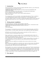
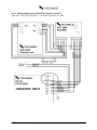
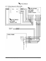
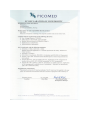
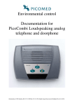
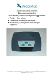
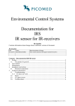
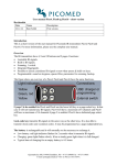
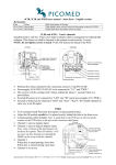
Environmental control Documentation for EFP 2005 doorphone To be used together with Picolo, PicoCombi and Erifox Revision history When changes are made on the product or in the documentation, this will be given a revision number. The list below keeps track of these changes. Date Name Description 19.10.05 Bent-Håvard Sollid. First version with English text. 01.07.06 Bent-Håvard Sollid. EC Declaration of Conformity updated with new directives. Added WEEE icon. Changed revisionlist to new type. 01.08.08 Bent-Håvard Sollid. New version of outdoor unit: - Ch 6.2.1, changed text. - Ch , 6.2.3, 6.2.4, changed wiring diagram. 01.01.12 Bent-Håvard Sollid. Added wiring diagram for the new version of PicoCombi, MK II. Contents – Documentation EFP 2005 1 Introduction ...................................................................................................................... 2 2 Getting started, installation ............................................................................................. 2 3 User manual ...................................................................................................................... 2 3.1 Accessories ................................................................................................................. 3 4 Maintenance ...................................................................................................................... 3 4.1 Cleaning ..................................................................................................................... 3 4.2 Outdoor use ................................................................................................................ 3 5 Troubleshooting................................................................................................................ 3 5.1 If errors arise .............................................................................................................. 4 6 Technical information ...................................................................................................... 4 6.1 Fixed mounting .......................................................................................................... 4 6.2 Electrical connections ................................................................................................ 4 6.2.1 Outdoor unit ........................................................................................................... 4 6.2.2 Amplifier box ......................................................................................................... 4 6.2.3 Wiring diagram for Picolo/PicoCombi version I ................................................... 6 6.2.4 Wiring diagram for Picolo/PicoCombi version II .................................................. 7 6.2.5 Wiring diagram for Erifox PABX .......................................................................... 8 6.3 Default (recycling) ..................................................................................................... 9 6.4 Technical data ............................................................................................................ 9 6.5 CE markings ............................................................................................................... 9 Brokelandsheia, N-4993 Sundebru, Ph +47 3711 9950 Fax +47 3711 9951 E-mail: [email protected] Org.no 962 211 631 MVA 1 Introduction This documentation is made for Picomeds doorphone EFP 2005, which is a part of Picomeds environmental system. It consists of 2 units: Amplifier-box made for indoor placement. It consists of necessary amplification and voicedirection control. Outdoor unit consisting of a box with a speaker, a microphone and a push-button. From the amplifier box there shall be cables to: Indoor unit (Picolo, PicoCombi or Erifox PABX). Signals and power. Outdoor unit. Signals. The equipment does not have any handset, only loudspeaking function. There is an built-in voice controlling function which controls voicedirection, i.e if the loudspeaker or the microphone shall be enabled. It is possible to regulate the volume from the outdoor unit, but it is recommended that the preset value is kept unaltered. EFP 2005 shall be powered with 12 VDC. 2 Getting started, installation The following parts are included when the product is delivered: Amplifier box, made to be connected to Picolo/PicoCombi or Erifox. A Picolo/PicoCombi version can not be connected to an Erifox version or vice verca. Outdoor unit. This documentation. The equipment is developed to be connected to Picomeds loudspeaking indoor units Picolo and PicoCombi, or an Erifox PABX. Indoor unit is not included in the EFP 2005 shipment. EFP 2005 made for Picolo/PicoCombi can not be connected to an Erifox version or v.v. The Erifox version is clearly marked with “Erifox”. Find a suitable place to mount the outdoor unit. It is recommended to place it where it is shielded for wind and precipitation. There is space for the users name on the outdoor unit. It can be marked with a label, waterproof pencil etc. Find a suitable place to mount the amplifier box. It shall be mounted indoor in a dry place. It is recommended that it is not more than 4-5 meters cable between the outdoor and the amplifier box. Mount cable between amplifier box and outdoor unit, connect as shown in the wiring diagram. Mount cable between amplifier box and indoor unit, connect as shown in the wiring diagram. Erifox version: the telephone line used for doorphone has to be enabled. This is done in programming mode. Find details in the PABX usermanual. The doorphone is now ready to be used together with an indoor unit. Test the communication. The outdoor units volume in the speaker can be adjusted with the potentiometer marked with “GAIN” on the PCB inside the amplifier box. It is recommended that the preset value is kept unaltered. A red light indicator (LED) is illuminated when the amplifier box is powered with 12 VDC. Position for the “GAIN” potentiometer and the LED is shown in chapter 6.2.3. 3 User manual EFP 2005 – loudspeaking doorphone Page 2. The outdoor unit has a pushbutton which shall be pressed by the visitor. The conversation is enabled by the user from the indoor unit (Picolo, PicoCombi or telephone via PABX). This process is described in the indoor units documentation. 3.1 Accessories Accessories for the EFP 2005 doorphone. The outdoor units frontfoil can be replaced if the users name shall be changed. 4 Maintenance EFP 2005 doorphone is developed to work without any need for adjustment etc. There are no fuses or batteries which has to be changed. 4.1 Cleaning The equipment should be cleaned when necessary. Wipe the equipment with a slightly damp cloth or an antistatic cloth. Never use a dry cloth, while this result in risk of static charges. It shall not be exposed for fluids in any way. 4.2 Outdoor use Picomeds EFP 2005 doorphone shall have the amplifier box mounted indoor, while the outdoor unit should be mounted in a shielded place. Attempt to find a place where it not will be exposed by wind, rain and snow. The reason for this, is that water will be able to get inside the box and degrade the equipments function. 5 Troubleshooting If your equipment does not behave as expected, first of all try to solve the problem yourself using the following table: Symptom Completely dead. Light indicator not illuminated. Possible cause No power connected to the indoor unit (the EFP 2005 is powered from the indoor unit). No sound in the speaker in the outdoor unit. No sound in the speaker in the indoor unit. No sound neither in the outdoor unit or in the indoor unit. Cable between amplifier box and outdoor unit. Cable between amplifier box and outdoor unit. Cable between the amplifier box and outdoor unit. Cable between the amplifier box and indoor unit. Cable between the amplifier box and outdoor unit. Cable between the amplifier box and indoor unit. Push-button does not function. EFP 2005 – loudspeaking doorphone Recommended action Ensure that the power supply is the correct one which was delivered with the equipment. Ensure that the power supply is connected to a functioning wall outlet. Ensure that the power supply is properly connected to the equipment. Check the “LS” cable. Check the “MIC” cable. Check wiring: LS, Mic, La and Lb. Check wiring both places. Page 3. There are no fuses inside the device which can be replaced. 5.1 If errors arise If there are errors which are not possible to solve, contact your supplier of the equipment, or the national distributor. Please make a note beneath of the telephone number to your supplier. Name Supplier: Telephone number, address etc. National distributor: 6 Technical information The amplifier box is made by: Injection moulded box in recyclable ABS-94HB. Printed circuit board (PCB) screwed into bottom part. The PCB has 3 terminal blocks: one for connection to outdoor unit, one for connection to indoor unit and one marked with “FREE”. This is made as a help to the technician if there is a need for joining wires etc. No one of the connecting points are connected to each other or to components on the PCB. A red LED illuminates when power is connected. Potentiometer (“GAIN”). Can be used to regulate speaker volume in outdoor unit. Outdoor unit: Front part with microphone, loudspeaker and pushbutton. Frontfoil glued on front part. Picomeds logo, product name and space made for the users name on it with a label, waterproof pen etc. Backside has 6 electrical connections. Frame for wall mounting. 6.1 Fixed mounting The amplifier box can be mounted vertically or horizontally as needed. The outdoor unit is made to placed vertically and shielded for wind, rain and snow. 6.2 Electrical connections 6.2.1 Outdoor unit On the back there is terminal blocks with connections. Connect as advised on wiring diagram. Connections are made for maximum 2,5 mm2 cable. Remove 6 mm of the insulation. 6.2.2 Amplifier box There are 3 terminal blocks in the amplifier box and each of them have 6 connections. Connections are made for maximum 2,5 mm2 cable. Remove 6 mm of the insulation. Terminal block at the lower right is for cable to indoor unit. EFP 2005 – loudspeaking doorphone Page 4. Terminal block at the lower left is for cable to outdoor unit. Terminal block at the top left is marked "FREE". This is made as a help to the technician if there is a need for joining wires etc. No one of the connection points are connected to each other or to components on the PCB. Description of the connections: 12V and GND is powersupply to the amplifier. Only use direct current (DC). La, Lb is sound between indoor unit and amplifier box. DB is DoorBell, one-pole switch in outdoor unit. Connects GND back to indoor unit. LS is LoudSpeaker, sound to loudspeaker in outdoor unit. Non-polarized. Mic+ and Mic- is sound from the outdoor units microphone. Polarized. EFP 2005 – loudspeaking doorphone Page 5. 6.2.3 Wiring diagram for Picolo/PicoCombi version I EFP 2005 – loudspeaking doorphone Page 6. 6.2.4 Wiring diagram for Picolo/PicoCombi version II OBS: this is for PicoCombi MK II – not same diagram as for MKI. EFP 2005 – loudspeaking doorphone Page 7. 6.2.5 Wiring diagram for Erifox PABX EFP 2005 – loudspeaking doorphone Page 8. 6.3 Default (recycling) The following shall be done on Picomeds EFP 2005 when it shall be used by a new user. If necessary, make a copy of this page, fill inn serial number, version and tick off the points which are done with signature and date at each point, and file it as your routines requires. Serial number: Check the equipment. Is there any physical damages, cracks etc in box or foil? Check that foil is not damaged, that it is fastened all around the edges and that it not has loosened from its surface. If it is marked with former users name, remove this marking. If not possible to remove name, replace foil (can be ordered from supplier). Clean the device. Ensure that all components are available, amplifier box and outdoor unit. Make a function check. The equipment has to be connected to an indoor unit. It is recommended to do this before the equipment is disconnected. Ensure that all functions are working properly: check if “ding-dong” is responding, and that it is possible to have 2-way communication between out- and in indoor units. Adjust potentiometer for outdoor loudspeaker volume (“GAIN”) clockwise until end-stop, thereafter counter clockwise 90º. Store. 6.4 Technical data Type Operating Power supply Current consumption Temperature Measurements Weight Programmable parameters Waste management Developed and manufactured in Picomed EFP 2005 doorphone. Pushbutton on outdoor unit. The conversation is activated from indoor unit (not included). Voice direction is electronically controlled. From indoor unit, 12 VDC. < 250 mA. Amplifier box: 0˚C to +40 C. Outdoor unit: -20˚C to +40 C. Amplifier box: LxWxH: 117 x 94 x 14 mm. Outdoor unit: LxWxH: 130 x 100 x 45 mm. Amplifier box: 160 g. Outdoor unit: 250 g. Outdoor volume can be adjusted by technician. It is recommended that the preset value is kept unaltered. Dispose as electronic waste. Norway. 6.5 CE markings Picomeds environmental control systems are developed and manufactured in accordance with EU directives, national regulations and harmonised standards which are applicable, and thereafter marked with the CE-mark. The Declaration of Conformity is in English version and it is set out on the next page. EFP 2005 – loudspeaking doorphone Page 9.