1
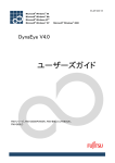
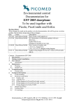
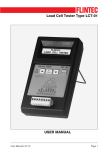
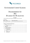
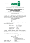
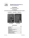
Service Manual Variants: for seca 952, 956 952 1309009 952 1309369 956 7021099 956 7021159 956 7021249 Service Manual Number 17-05-01-351Valid as of: Description: Chairscale digital, with LC electronic Content: Repair instructions 30-34-00-801 Cableplan 08-02-06-047 c Replacement 30-34-00-787 Spare parts 30-34-00-794 Manual number: 17-05-01-351- 01.05.2010 Repair Instructions MODEL 952 / 956 Contents 1 General Information......................................................................................... 2 1.1 Typeplates ............................................................................................ 2 1.2 Design and Function ............................................................................. 3 1.2.1 Design ........................................................................................... 3 1.2.2 Function......................................................................................... 3 2 Maintenance ................................................................................................... 4 2.1 Adjustment ........................................................................................... 4 2.1.1 General.......................................................................................... 4 2.1.2 Carrying Out .................................................................................. 4 3 Errors.............................................................................................................. 6 3.1 Error Symptoms.................................................................................... 6 3.2 Error Messages Generated by the Scale................................................ 7 4 Measurements ................................................................................................ 8 4.1 Supply Voltage...................................................................................... 8 4.2 Display Electronics and Load Cell.......................................................... 8 4.2.1 Measurement Using an Oscilloscope.............................................. 8 4.2.2 Measurement Using a Multimeter ................................................... 9 A Index of Tables.............................................................................................. 11 B Index of Diagrams ......................................................................................... 12 C Appendixes................................................................................................... 13 General Information 1 General Information These service instructions are intended for specialist staff charged with maintenance and repair of the scale. These persons must be familiar with all the relevant electro-technical regulations and must adhere to them any time. These instructions are not suitable for users without specialist knowledge. What is the structure of this document and how should you read it? Section 1 provides a short overview of the most important points for service. We recommend you should read it completely. Section 2 deals with the maintenance of the scale, i.e. work that may have to be carried out more frequently. This section can be read as and when required. Troubleshooting is covered in section 4, where you find detailed descriptions of various measurements intended to identify specific errors. Starting point for troubleshooting is section 0, which includes an overview of error descriptions and the inspection steps required to identify them. 1.1 Type plates To enable you to identify the device, information about the model and serial number is found on the underside or on the frame of the scale (see Note down this information so that you have it on hand in case you need to contact us for queries or spare parts orders. Figure 1: Type plate (left: approved; right: non-approved) 23.04.2010Kraus/Rei 2 30-34-00-801 General Information 1.2 Design and Function 1.2.1 Design The scale mainly consists of four parts: the frame, the platform, a housing with printed circuit board (scale electronics with integrated display) and a single measuring sensor (load cell). The measuring sensor connects the platform with the frame and is connected to the scale electronics via a cable. 1.2.2 Function A force acting on the platform leads to elastic deformation of the load cell. A corresponding analog signal is supplied, which changes linearly with the force applied. This signal is measured and evaluated by the scale electronics and displayed as a weight value. Figure 2: Functional diagram shows the functional diagram of the scale. Figure 2: Functional diagram 23.04.2010Kraus/Rei 3 30-34-00-801 Maintenance 2 Maintenance The following section provides an overview of all maintenance jobs which can be carried out. 2.1 Adjustment 2.1.1 General To compensate for linear measuring deviations, which occur e.g. as a result of gravity variations in different gravity zones, the scale offers an adjustment feature. This adjustment must also be carried out whenever the load cell is replaced. 2.1.2 Carrying Out The adjustment function is activated using a slide switch/jumper on the PCB (depending on the scale type; see Figure 3: Slide switch (left) in adjustment function activated position / jumper contact (right): adjustment function is activated when connected After activating the slide switch/jumper, the scale must be switched on to start the adjustment function. Figure 3: Slide switch (left) in adjustment function activated position / jumper contact (right): adjustment function is activated when connected To carry out adjustment, the following steps are required: Switch on the scale and check the battery status (see note). Do not continue adjustment when the batteries are low. Then switch off the scale and open the integrated display by unscrewing the four screws. This allows access to the slide switch/jumper on the PCB, which can now be operated/placed (see Figure 3: Slide switch (left) in adjustment function activated position / jumper contact (right): adjustment function is activated when connected 23.04.2010Kraus/Rei 4 30-34-00-801 Maintenance Set the scale up properly again and then switch it on. After starting the scale, the segment test comes up and then the display flashes to request that a specific weight be placed on the scale. Place the necessary weight in the centre of the weighing platform. Once a stable and correct weight value has been detected, the LCD stops flashing and a calibration value is calculated and saved. The scale switches off automatically a few moments later. If the LCD does not stop flashing, this indicates that the weight measured is below the expected weight value or that it is not possible to determine a stable weight value (as a result of vibrations etc.). Next remove the weight from the scale, return the slide switch on the PCB to its original position (or alternatively remove the jumper) and refit the display. Now set the scale up again and then switch it on. Afterwards, place an adjustment weight on the scale and check whether the correct weight is displayed. If you are working on an approved scale, the scale must be sealed again after successful adjustment in accordance with national regulations. Note: Monitoring of the battery voltage is not possible during the adjustment procedure. Therefore make sure to check the battery voltage before and after adjustment. You can do so by switching on the scale and watching the display. If the battery voltage is low, either the early battery warning symbol or the "bAtt" display is activated. If one of the two displays occurs before or immediately after adjustment, the batteries must be replaced and adjustment must be repeated. 23.04.2010Kraus/Rei 5 30-34-00-801 Errors 3 Errors The following section provides an overview of possible error symptoms, their causes and the steps required to remedy the error. In addition, the error messages generated by the scale and ways to eliminate them are explained. 3.1 Error Symptoms Error description Possible causes Battery not inserted or flat Check the batteries Voltage supply defective See section 4 Keyboard defective or not connected Check cable connections, check cable and keyboard for interruptions, replace if necessary Packaging / transport locking device not removed completely Check the scale Scale not correctly adjusted See section 2 Load cell damaged See Replacement Instructions 30-34-00787 Force transmission into load cell interrupted Check base frame for damage or incorrect assembly Display electronics/load cell damaged See Replacement Instructions 30-34-00787 Scale does not start Scale shows no weight or an incorrect weight Measured values vary greatly Remedy Table 1: Error symptoms 23.04.2010Kraus/Rei 6 30-34-00-801 Errors 3.2 Error Messages Generated by the Scale Scale displays Er 11 Cause Load cell defective or supply lines damaged Admissible switch-on zero point overshot Er 12 Remedy See sections 4.1 Check initial load and reduce if necessary or Load cell damaged See sections 4.1 Er 16 Device failed to determine a valid switch-on zero point Avoid subjecting the scale to vibrations during start-up Er 40 EEPROM defective/deleted Replace display electronics/load cell Er 50 Flash memory defective Replace display electronics/load cell Table 2: Scale error messages 23.04.2010Kraus/Rei 7 30-34-00-801 Measurements 4 Measurements The following section provides an overview of measurements which can be performed to identify specific errors. 4.1 Supply Voltage Measuring the supply voltage at the electronics board provides information on whether the supply lines to the battery compartment and/or the power supply unit are OK. When operating on battery power you should measure approx. 9V and approx. 12V when using a power supply unit. Carry out the measurement by connecting a multimeter to measuring points A and B (see Appendix 1). 4.2 Display Electronics and Load Cell The most effective way to identify a defect of the load cell is using an oscilloscope (see 4.2); if you do not have this type of equipment at your disposal, you can alternatively use a multimeter (see 0). A multimeter measurement, however, is less conclusive so that it should always be second choice. 4.2.1 Measurement Using an Oscilloscope To carry out the measurement, switch on the scale and attach the probe head at measuring point C (see Appendix 1). Measuring point B (see Appendix 1) is used as ground contact. Make sure that you pierce the paint with the probe tip. 2.5V Figure 4: Output signal of AD converter when load cell and supply line are intact 23.04.2010Kraus/Rei 8 30-34-00-801 Measurements On the oscilloscope you should now see recurrent ramps starting from a 2.5V line, the height of which depends on the load on the load cell. When you press on the load cell, the amplitude of the four ramps which come after the large ramp increases (see Figure 4: Output signal of AD converter when load cell and supply line are intact For the measurement, the following settings are recommended: time basis 10ms, resolution 500mV, trigger level 3V (rising edge). 5V Figure 5: Output signal of AD converter when load cell or supply line is defective If load cells are defective, this is usually easy to identify. Sometimes they distort the signal to such an extent that the ramps no longer start at 2.5V (see Figure 5: Output signal of AD converter when load cell or supply line is defective , 1V resolution). 4.2.2 Measurement Using a Multimeter First of all, unsolder the load cell from the electronics and measure the resistance between the different connecting wires (see Figure 6: Design of a load cell . The table below shows the values to be expected: Measurement between Ohmic resistance [Ω] V+ and V- 405±10 Sig+ and Sig- 350±5 Sig+/Sig- and V+/V- 290±5 Sig+/Sig-/V+/V- and aluminium body of approaches infinity the load cell Table 3: Ohmic resistances of load cell 23.04.2010Kraus/Rei 9 30-34-00-801 Measurements The relevant cabling diagram shows the designations and associated cable colour. The measured values only have a limited informative value; however, as even a defective load cell can supply absolutely correct values when no load is placed on it (a more qualified result can be obtained using an oscilloscope to carry out the measurement). If the load cell supplies incorrect values when unloaded, it is definitely defective. Figure 6: Design of a load cell 23.04.2010Kraus/Rei 10 30-34-00-801 A Index of Tables 1. Table1: Error symptoms ................................................................................ 6 2. Table 2: Scale error messages ...................................................................... 7 3. Table 3: Ohmic resistances of load cell.......................................................... 9 23.04.2010Kraus/Rei 11 30-34-00-801 B Index of Diagrams 1. Figure 1: Type plate (left: approved; right: non-approved) .............................. 2 2. Figure 2: Functional diagram ......................................................................... 3 3. Figure 3: Slide switch (left) in adjustment function activated position / jumper contact (right): adjustment function is activated when connected ....... 4 4. Figure 4: Output signal of AD converter when load cell and supply line are intact....................................................................................................... 8 5. Figure 5: Output signal of AD converter when load cell or supply line is defective ....................................................................................................... 9 6. Figure 6: Design of a load cell...................................................................... 10 23.04.2010Kraus/Rei 12 30-34-00-801 C Appendixes Appendix 1: Measuring points on SECA module 08-06-18-160 23.04.2010Kraus/Rei 13 30-34-00-801 A B C D E F B A - (schwarz | black) + (rot | red) Batterie-Anschlusskabel Battery connection cable A 7 8 7 6 A-A 6 Batterie-Anschluss Battery connection B Ansicht auf Platine von unten. View on the electronic board from below. B-B 8 Batterie-Anschluss Battery connection 4 5 b HAMBURG 1:1 Kabelplan Mod. 952, 956 Cabel scheme mod. 952, 956 Benennung / TITLE : 27.11.2008 Aschke 24.11.2009 Winterberg ja | yes ja | yes ja | yes nein | no ja | yes Zugelassen admitted 1 B C D E F Blatt/SHEET 1/1 08-02-06-047 R:\ARCHIV_DBWORKS\Firma\08-\08-02-\08-02-06-047 Nr. / NO. : ALL RIGHTS CONCERNING THIS DOCUMENT AND ITS CONTENTS RESERVED. Alle Rechte an und aus diesen Unterlagen verbleiben seca gmbh. & co. kg. weiß | white rot | red weiß | white rot | red rot | red weiß | white rot | red weiß | white weiß | white gelb | yellow DMS-Low DMS-HIGH Erstellt / DRAWN Geprüft / APPROVED Ver. c PROJECTION 10.12.2008 Asch. 15.07.2009 Rein. 23.11.2009 Rein. (1x) load cell add scale change a b c Maßstab / SCALE : Werkstoff / MATERIAL : Änd.Mitteil. / CHANGE: Index / REVISION: Datum/Name: schwarz | black schwarz | black schwarz | black grün | green Wägezellen-Kabel Loadcell cable Batteriepack Battery pack Wägezellen-Kabel. Farbzuordnung siehe Tabelle. Loadcell cable. Colour allocation see table. DMS-Low DMS-High WZ-Type DMS-Vcc DMS-GND DMS-GND DMS-Vcc HBM PW10 C4 250 kg blau | blue schwarz | black TEDEA Mod.Nr. 1242 grün | green Kogean/V-Care 250 kg grün | green Flintec PC46 grün | green Scaime braun | brown AHN250C4SH10e 2 Distanzplatte (Schaumstoff) Distance plate (foamed material) Batterie-Anschlusskabel Battery connection cable Platine Electronic board 3 Wägezellen-Kabel Ansicht ins Batteriefach von unten. Loadcell cable View into the batterie box from below. Wägezellen-Kabel Loadcell cable 5 Donnerstag, 3. Dezember 2009 18:52:35 Replacement instructions seca 952 / 956 22.04.2010/Rei 1 30-34-00-787 Replacement instructions seca 952 / 956 Safety measures: Before starting any work on the scale, first disconnect the power supply (mains and batteries). Safety instructions regarding the prevention of electrostatic charging (ESD protective measures): ESD protective measures (electrostatic discharge) must be taken whenever work is performed on electronic components. Please observe the following precautions so that you can safely repair the scale: Ground yourself using an antistatic wrist strap. Wear ESD safe shoes. Wear ESD compatible clothing. Only carry out the work to be performed in an electrostatic protective area. Make sure the floor is electrically conductive. Only use ESD proof tools. Special notes regarding the replacement and installation of: Replacing bubble level A (model 956 only) Only remove bubble level A if it is defective. Destruction of the bubble level cannot be avoided, and a new bubble level can only be fitted by a skilled person working with great care. Lever out bubble level A from the bearing bush. Scrape out the plaster from the bearing bush and thoroughly clean the bush. When fixing the new bubble level with plaster align it so that it indicates the horizontal position. Alignment must be repeated until the plaster has fully hardened. 22.04.2010/Rei 2 30-34-00-787 Replacement instructions seca 952 / 956 Removing foot rests B: Remove plug C. Unscrew the two screws and bushes D. You can now pull off foot rest B. Attention: When refitting foot rest B make sure threaded plate D1 is correctly seated in the pipe! Replacing arm rests G When replacing arm rests G take care that screw connections H are only tightened so much that the rests can still move freely. 22.04.2010/Rei 3 30-34-00-787 Replacement instructions seca 952 / 956 Replacing display housing I with electronics and load cell K adjusted Take great care when replacing the display housing I with electronics and load cell K in order not to detach any cables from the printed circuit board. The tightening torque for the load cell screw connections L is Mt = 12.5 Nm. Setting the stop screws Z for overload protection After tightening the load cell K, the stop screws Z should be turned in so far that they are in light contact with the load cell. Afterwards turn them back by exactly 2 turns. Secure the stop screws in this position with a screwlock adhesive. 22.04.2010/Rei 4 30-34-00-787 Spare parts list seca 952, 956 Chairscale with LC Elektronik Item Articel-no. Designation Price stage Chairscale drawing page 2 01 02-02-03-105-008 02-02-03-121-008 Baseframe, light grey Baseframe, light grey (red. seat height )Japan, China 45 45 02 02-04-03-078-008 02-04-03-078-006 Seat frame, light grey Seat frame, distant blue , WIBU 36 36 03 02-04-03-065-008 02-04-03-065-006 Arm rest right, light grey Arm rest right, distant blue , WIBU 35 35 04 02-12-15-248-009 Seat 35 05 02-02-03-120-008 Handlebar frame, light grey 33 06 08-06-12-099-509 08-06-12-101-509 Load cell with electronic compl. adjusted incl. display housing without frontfoil Load cell with electronic calibrated compl. adjusted incl. display housing without frontfoil 45 50 07 02-04-03-066-008 02-04-03-066-006 Arm rest left, light grey Arm rest left, distant blue, WIBU 35 35 08 01-17-01-203-009 50-90-00-710-009 Bubble level (only mod. 956) Cap (only Mod. 952) 15 01 09 66-30-42-051-009 Clip holder 01 10 02-11-04-060-509 Guide roll compl. with wheel 30 11 08-04-02-211-009 Pressure plate (load cell) 15 12 02-11-04-228-009 Roller 22 13 01-16-02-268-009 Thread base plate (foot rest) 10 14 01-16-02-269-009 Socket 05 15 01-13-05-458-009 Foot rest 20 Display housing drawing page 3 18 34-02-01-281-009 Cover for battery compartment 05 19 66-30-60-025-009 Battery holder 10 20 34-02-01-282-009 Spacer 01 21 34-02-01-280-009 Display housing 20 22 34-02-01-272-009 Window 10 23 14-05-08-230-009 14-05-08-231-009 Sticker weighing data mod. 952 Sticker weighing data mod. 956 01 01 24 34-02-01-265-009 Display cover 10 25 34-02-04-403-009 34-02-04-420-009 34-02-04-423-009 34-02-04-424-009 Frontfoil mod. 952 Frontfoil Mod. 956 calibrated Frontfoil Mod. 956 China calibrated Frontfoil Mod. 956 Japan calibrated 25 25 25 25 26 01-13-04-351-009 Distance plate 01 (27) 18-01-07-056-009 18-01-07-059-009 Package compl. 952/956 Package compl.. 956 China, 956 Japan 23 23 20.04.2010/Rei 1/3 30-34-00-794 Spare parts list 20.04.2010/Rei 2/3 30-34-00-794 Spare parts list 20.04.2010/Rei 3/3 30-34-00-794