1
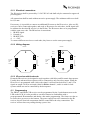
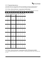
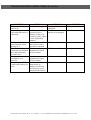
Environmental Control
Documentation for
Picomed ER2AC and ER4AC
IR-receivers with 2 and 4
channels
Brokelandsheia, 4993 Sundebru, Tlf +47 3711 9950 Fax +47 3711 9951 E-mail: [email protected] Foretaksnr 962 211 631 MVA
Documentation ER2AC and ER4AC IR-receiver
Versions
Date
210205
Made by
Bent-Håvard Sollid
Comment
English version, based on Norwegian version 0303.
Table of contents
1
User manual ........................................................................................................................3
1.1 Water, humidity and cleaning.........................................................................................3
1.2 Cleaning..........................................................................................................................3
1.3 Malfunctioning ...............................................................................................................3
2
Technical documentation....................................................................................................3
2.1 Periodically maintenance................................................................................................3
2.2 Mounting ........................................................................................................................3
2.2.1 Electrical connections.............................................................................................4
2.2.2 Wiring diagram.......................................................................................................4
2.2.3 IR-receiver with lock-code .....................................................................................4
2.3 Programming ..................................................................................................................4
2.3.1 How to program the IR-receiver.............................................................................5
2.3.2 LED behaviour during programming mode ...........................................................5
2.3.3 Programming memory............................................................................................6
2.3.4 User code and channel - programmed with buttons ...............................................6
2.3.5 User code and channel - programmed with an IR-remotecontroller ......................6
2.3.6 Lockcode - programmed with buttons....................................................................7
2.3.7 Lockcode - programmed with an IR-remote controller..........................................7
2.3.8 Relay functions .......................................................................................................7
2.4 Recycling ........................................................................................................................8
3
Productinformation.............................................................................................................8
3.1 Accessories .....................................................................................................................8
3.2 Technical data.................................................................................................................9
ER2AC, ER4AC
Page 2.
1 User manual
Picomed ER2AC and ER4AC receivers for InfraRed (IR) light receives IR light emitted from
IR-transmitters. To receive these signals it is an advantage that the receiver not is covered by
anything which can block the emitted signal from the transmitter. Usually the IR-signals will
be reflected by floor, walls and roof, so in most cases there is no need to point directly against
the receiver with the IR-transmitter. The distance between the receiver and the transmitter
should be more than 1 metres to make the most of this reflection effect.
The receiver will be controlled by a transmitter with the same type of IR-signals and the
correct codes.
There is no need for maintenance for the IR-receiver, and there is no batteries etc. which has
to be changed. If the IR-receiver needs to be cleaned, it can be cleaned with a humid cloth,
alternatively use a mild soap.
There is a red light indicator in the front of the IR-receivers which will lit when it receives a
known IR-signal. Keep in mind that it should not be covered by anything which can prevent
the IR-signals to reach it, and it should not be exposed for direct sunlight.
1.1 Water, humidity and cleaning
Picomed ER2AC and ER4AC is ment for indoor use. Do not spell liquids on the receiver
while it can destroy it.
1.2 Cleaning
It can be cleaned with a humid cloth, alternatively use a mild soap.
1.3 Malfunctioning
Contact:
Name
Telephonenumber
2 Technical documentation
The IR-receiver is ment to be wall-mounted in a standard box. It can also be flush mounted in
a standard box. There is no need for any dissasembling for periodical maintenance,
inspections or repairments.
2.1 Periodically maintenance
The IR-receiver is developed to work without any need for periodical maintenance. There is
no internal battery to be changed.
2.2 Mounting
Picomeds IR-receiveres ER2AC and ER4AC is ment for wall mounting. All electrical wires
shall be disconnected when mounting the receiver. It shall be mounted in a place where it not
will be covered by anything which can block the IR-signals. Even so, it is very often possible
to place it behind curtains etc, and still it will work to the users satisfaction. Direct sunlight
which shines on the receiver will very often reduce the receivers sensitivity.
ER2AC, ER4AC
Page 3.
2.2.1 Electrical connections
The IR-receiver shall be powered by 12-24 VDC/AC and shall only be connected to approved
powersupplies.
All connections shall be made without an active powersupply. The minimum cable area shall
be 0,22 mm2.
If necessary, it is possible to connect an additional IR-sensor to the IR-receiver. Also two IRreceivers can be connected together, and work as IR-sensors for each other. An IR-signal will
be adducted to the other IR-receiver via the IR-bus. The IR-sensors have to be programmed
with the same user code. The IR-bus has 4 connections:
1. IR-BUS signal.
2. Ground (-).
3. IR-BUS LED.
4. =< + 24V.
To connect different receivers to each other, they have to use the same powersupply.
2.2.2 Wiring diagram
ER2AC
ER4AC
RL4
RL3
RL1
24 VDC
GND
IR
LED
RL1
24 VDC
GND
IR
LED
RL2
RL2
2.2.3 IR-receiver with lock-code
Picomeds IR-receivers are designed to work together with Abloy and Picomatic dooropeners.
Usually these advanced door-openers will be connected to only one relay-output. When the
IR-receiver is programmed with a lock-code signal, it will activate both relay 1 and 2. The
signal on output 2 will be activated a little bit before channel 1, and it is ment for locksystems which not can be controlled by the dooropener.
2.3 Programming
The ER2AC and ER4AC IR-receiver can be programmed by the 2 push-buttons next to the
LED on the PCB. It is also possible to use these buttons in combination with a
preprogrammed IR-transmitter and obtain a fast-mode programming. The front-cover has to
be removed to get access to the buttons. The power supply has to be connected to the IRreceiver, but no electrical components shall be connected to the relay connections. The
receiver will not loose any settings during a power loss.
ER2AC, ER4AC
Page 4.
”1” knapp
”0” knapp
Lysdiode
IR-sensor
The main components on the PCB are two programming buttons ("1" knapp, "0" knapp), one
LED (Lysdiode) and a IR-sensor on the PCB.
The programming buttons are indicated as "0" and "1" (binary notation). The following
parameters can be programmed:
User code and channels.
Lockcode.
Working mode for the relays.
User code and channel can be set with the help of a preprogrammed IR-remote controller. The
working mode for the relays has to be set with the programming buttons. The receiver can be
reprogrammed any time, and there is no limit for how many times it can be reprogrammed.
2.3.1 How to program the IR-receiver
Enter programmaing mode by press & hold the "0" button for 5 seconds. Let off the
button when the LED is lightning.
The programming can be done by writing "programming-words"; PW, which consists of
sequences containing "0" and "1". The PW's should be written down before the
programming starts to avoid any trouble due to timeouts during the programming.
If a wrong input is made, press an hold the "0" button for 5 seconds to leave the PW and
go back to programming mode without saving data.
There will be a timeout after 60 seconds if no keys are pressed.
When entering of a PW is started a pause of more than 15 seconds between two bits will
result in timeout of a PW.
Only completed PW will be stored.
2.3.2 LED behaviour during programming mode
In programming mode the LED will be on.
When a PW is started, the LED will flashing rapidly.
When entering a bit, the LED will turn of for a moment.
When a PW is done and all bits accepted, the LED will flash slowly twice.
The IR-receiver will have the same behaviour when it is programmed by the help of an IRtransmitter.
ER2AC, ER4AC
Page 5.
2.3.3 Programming memory
All settings which are programmed will be stored and they will not be changed during a
power loss. The power supply has to be connected during the programming sequence.
2.3.4 User code and channel - programmed with buttons
PW to use for choosing the user code shall start with " 1 0 0 0". The PW shall be like this:
1
0
0
0
A4 A3 A2 A1 A0 D3 D2 D1 D0
The table beneath shows the usercodes and channels:
Gewa chanUsercode
A4 A3 A2 A1 A0
nel group
0
0
0
0
0
0
0
1
1
0
0
0
0
1
2
2
0
0
0
1
0
3
3
0
0
0
1
1
0
4
0
0
1
0
0
1
5
0
0
1
0
1
2
6
0
0
1
1
0
3
7
0
0
1
1
1
0
8
0
1
0
0
0
1
9
0
1
0
0
1
2
10
0
1
0
1
0
3
11
0
1
0
1
1
0
12
0
1
1
0
0
1
13
0
1
1
0
1
2
14
0
1
1
1
0
3
15
0
1
1
1
1
0
16
1
0
0
0
0
1
17
1
0
0
0
1
2
18
1
0
0
1
0
3
19
1
0
0
1
1
0
20
1
0
1
0
0
1
21
1
0
1
0
1
2
22
1
0
1
1
0
3
23
1
0
1
1
1
0
24
1
1
0
0
0
1
25
1
1
0
0
1
2
26
1
1
0
1
0
3
27
1
1
0
1
1
0
28
1
1
1
0
0
1
29
1
1
1
0
1
2
30
1
1
1
1
0
3
31
1
1
1
1
1
2.3.5 User code and channel - programmed with an IR-remotecontroller
A fast mode programming mode is also available. A preprogrammed IR-remote controller can
be used.
ER2AC, ER4AC
Page 6.
Press and hold the "0"-button for 5 seconds to enter the programming mode. The LED
shall be lightning.
Press the "1" button once, the LED will start flashing rapidly.
Transmit the signal from the IR-remote which shall control the first relay in the IRreceiver.
The LED will flash twice.
Finish by press & hold the "0" - buttons for 5 seconds.
The IR-receiver will read the IR-signal and store it in its memory. When programming the
receiver in this way, ONLY the signaltype programmed in the IR-transmitter will be stored. If
the IR-receiver shall respond to more than one IR-signal, the IR-receiver shall be programmed
with the programming buttons.
2.3.6 Lockcode - programmed with buttons
The lockcode is a special code consisting of 12 bits to obtain higher security. PW to use for
choosing the Lock code shall start with "0". The PW shall be like this:
0
XXX
XXX
XXX
XXX
Press and hold the "0" button for 5 seconds and let off the button when the LED lit.
Press the "0" button once, the LED will start flashing rapidly.
Enter the 12 bit lockcode to be used.
The LED will flash twice.
Finish by press & hold the "0" - buttons for 5 seconds.
2.3.7 Lockcode - programmed with an IR-remote controller
A fast mode programming mode is also available. A preprogrammed IR-remote controller can
be used.
Press and hold the "0"-button for 5 seconds to enter the programming mode. The LED
shall be lightning.
Press the "0" button once, the LED will start flashing rapidly.
Transmit the lock-code signal from the IR-remote.
The LED will flash twice.
Finish by press & hold the "0" - buttons for 5 seconds.
2.3.8 Relay functions
The relay functions can be set to:
On/Off.
Impulse (1 or 4 seconds).
Hold.
This can be set with the programming buttons. Each channel (relay) can be programmed
individually.
PW to use for relay functions shall start with "1 1 0 0 0". The PW shall be like this:
1 1 0 0 0 X0 Y0
X1 Y1
X2 Y2
X3 Y3
Setting
Xn Yn
0
0
0
1
Output function on the relay
On/Off
Impulse 1 second
ER2AC, ER4AC
Page 7.
1
1
0
1
Impulse 4 seconds
Hold
2.4 Recycling
When the IR-receiver shall be recycled to be used by an other user, the following should be
done. If there is any need to file this process, make copies of this page, fill in serialnumber
and make a cross next to each point to be done.
Serialnumber:
Check the IR-receiver for damages.
Clean it.
Make a functional test1.
Reprogram the ER x AC IR-receiver so IR-formats and usercodes used by a person
not can be misused in any circumstances. The following settings are
recommended:
Usercode 0.
Channelgroup (Gewa) 0.
Channel 0.
Format New Assistant.
3 Productinformation
Picomed ER2AC and Picomed ER4AC IR-receivers have 2 or 4 channels controlled by
infrared (IR) light. The receivers are developed to control lov-voltage products up to 48 V.
They can also control 230 VAC via external relays. They shall be powered with 12-24
VAC/VDC. They can be programmed to receive ordinary codes or lock codes. They can read
the following IR-formats:
New Assistant, 32 usercodes with 16 channels in each.
New Assistant lockcode, 12 bit.
Gewa Infralink, 4 groups with 16 channels in each.
Gewa Infralink lockcode, old 10 bit.
Gewa Infralink lockcode, new12 bit.
The IR-receiver can be programmed to respond on both New Assistant and Gewa if needed.
ER2AC has 2 channels (relays).
ER4AC has 4 channels (relays).
Each relay output can be individually programmed to on/off, hold or impuls. If the IRreceiver is programmed to respond on lock-codes it will only work on channel/relay 1.
3.1 Accessories
The IR-receiver is assembled with a printed circuit board inside a plastic box. On the front
there is a keypad foil with keys, product name and a light indicator. The partnumbers are:
Description
Infrared receiver 2 channels
Infrared receiver 4 channels
Picomed partnumber
ER2AC
ER4AC
1
A functional test should be done together with an IR-transmitter. Tip: do it before the IR-receiver is
dismounted. Both the IR-receiver and the IR-transmitter has to be prerogrammed with the same user code and
channel. Ensure that the IR-receiver responds on the receiverd IR-signals.
ER2AC, ER4AC
Page 8.
3.2 Technical data
Type
Controlled by
Number of channels
Powersupply
Current consumption
Temperature
Connections
Weight
Materiale
Settings
Neccessary depth when flush
mounting
ER2AC, ER4AC
Picomed ER2AC/ER4AC infrared receiver 2/4 channels.
From an IR remotecontrol.
2/4 potential free relays, 0,5 A/48 Volt.
External powersupply 9-24 VAC/DC.
50 mA.
-10 up to + 40 C.
Internal screw terminals.
Ca 100 g.
Plastic.
Usercode.
Channel.
Lockcode.
Relay working mode.
35 mm.
Page 9.
TROUBLE SHOOTING on ER2AC, ER4AC, IR-receivers
SYMPTOM
The receiver does not
work at all
The receiver does not
work when IR-sensor is
connected
ACTION I
Check power supply.
ACTION II
ACTION III
Disconnect IR-sensor if Call Your technichian
connected
The IR-sensor is defect Call Your technichian
and has to be changed
The IR-sensor is
exposed to direct
sunshine. It has to be
moved to a place where
it not is exposed by
sunshine
The receiver does not
It has to be moved to a Call Your technichian
work when the sun is
place where it not is
shining on it
exposed by sunshine
The receiver is
Not correct
Call Your technichian
connected to a common programmed. Check
door and works only
the user manual
for some users
The receiver works
Not correct
Call Your technichian
somethimes or in
programmed. Check
intervals
the user manual
The receiver works for The receiver is
Call Your technichian
a while and seems to be connected to an
reset
inductive load (relay
etc) which not is not
protected with a diode.
Brokelandsheia, 4993 Sundebru, Tlf +47 3711 9950 Fax +47 3711 9951 E-mail: [email protected] Foretaksnr 962 211 631 MVA


![[ENG] CE60-3 GSM Software ComCE v4-2](http://vs1.manualzilla.com/store/data/005829621_1-1503a18c5b086c34f94e34b38a52b968-150x150.png)