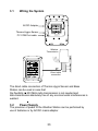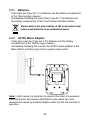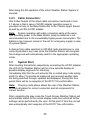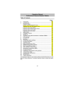
1
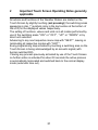
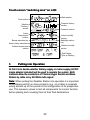
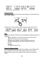
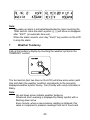
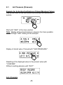
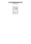
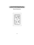
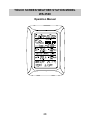
TOUCH SCREEN WEATHER STATION MODEL WS-3500 Operation Manual 28 Table of Contents 1 ...................... General 2 ....................... Important Touch Screen Operating Notes generally applicable 3 ...................... Putting into Operation 3.1 ................ Wiring the System 3.2 ................ Power Supply 3.2.1 .......... Batteries 3.2.2 .......... AC/DC Mains Adapter 3.2.3 .......... Cable Connection 3.3 ................ System Start 3.4 ................ Placement 4 ...................... Setting Up 5 ...................... Display of stored Min/Max Values and Alarm Value Settings 6 ...................... Radio Controlled DCF77 Clock 7 ...................... Weather Tendency 8 ...................... Air Pressure History 9 ...................... Operating and Setting of various Functions 9.1 ................ Air Pressure 10 .................... Additional Information to Function Outdoor Temperature 11 .................... Operating and Setting of Functions Backlight, Buzzer and Alarm section 11.1 .............. EL Backlight 11.2 .............. Buzzer 11.3 .............. Alarm 12 .................... PC Connection 12.1 .............. Data Storage 12.2 .............. Data Recall 12.3 .............. Connections and Software 13 .................... Technical Data 13.1 .............. Outdoor Data 13.2 .............. Data Transmission by 433 MHz Signal 13.3 .............. Data Transmission by Cable 13.4 .............. Indoor Data 13.5 .............. Power Supply 13.6 .............. PC Connection 13.7 ........... Dimensions 14 ................. Liability Disclaimer 29 1 General Important Note: Before inserting batteries to the units, please carefully read the operation manual. The shipping contents of the Touch Screen Weather Station WS-3500 include a Base Station (Receiver), a Thermo-Hygro Sensor (433 MHz Transmitter), the respective Connecting Cables, an AC/DC Mains Adapter and a PC Software Package on CD-ROM. The Base Station is equipped with a Touch Screen LCD Monitor and allows by use of comprehensive menu control the display of a vast variety of time and weather data (from top to bottom): Radio Controlled Time (Time) Calendar (Date) Weather Forecast (Tendency) Air Pressure and Air Pressure History (Pressure, Pressure History) Indoor Temperature and Humidity (Indoor Temp, Humidity) Outdoor Temperature and Humidity (Outdoor Temp, Humidity) Furthermore the display of a number of additional data can be realised by use of certain switching combinations (see further down). Note: In case the menu is used all these indications are temporarily replaced by the menu steps directly operable from the text section. As an important feature exceeding the display on the LCD Monitor the Weather Station allows by cable and software the readout of all measured and displayed time and weather data in form of complete history data sets, their processing and graphic presentation on a PC as well as their tie on to Internet Web Sites. 30 2 Important Touch Screen Operating Notes generally applicable All actions and functions of the Weather Station are started on the Touch Screen by slightly touching (not pressing!) the switching areas appearing in star ( )٭symbols (only in the text section at the bottom of the LCD) or the displayed values respectively. The setting of functions, values and units is in all modes performed by use of the switching areas ٭ON ٭or ٭OFF٭, ٭UP ٭or ٭DOWN ٭or by direct unit selection. Advancing to any next respective menu step with ٭NEXT٭, leaving or terminating all respective modes with ٭EXIT٭. Every programming step activated by touching a switching area on the Touch Screen is being acknowledged by an acoustic signal (with buzzer switched ON). If during any process previously activated by use of the Touch Screen no further action is activated for about 30 seconds the active process is automatically terminated and switched back to the normal display mode (automatic time out). 31 Touch screen "switching area" on LCD: Date section Time section Pressure History section Weather Tendency section Pressure section Indoor Temperature section Buzzer selection key Indoor humidity section Backlight section key Alarm history selection Outdoor humidity section Outdoor temperature section Text Display (Set up Display) 3 Putting into Operation At first it is to decide whether battery supply or mains supply (AC/DC mains adapter included) will be used to operate the system. Both methods allow the connection of Thermo-Hygro Sensor and Base Station by cable or by 433 MHz radio signal. Note: When putting the Weather Station into operation it is important to tentatively perform in close proximity (e.g. on a table) a complete wiring and set up of the system in the configuration of its prospective use. This measure serves to test all components for correct function before placing and mounting them at their final destinations. 32 3.1 Wiring the System Thermo-Hygro-Sensor PC COM Port cable OUTDOOR TX AC/DC-Adapter Wireless Transmission Direct cable connection The direct cable connection of Thermo-Hygro Sensor and Base Station can be used in case that: the flexibility of 433 MHz radio transmission is not needed and data transmission absolutely free of any environmental interferences is wanted. 3.2 Power Supply The provision of power to the Weather Station can be performed by use of batteries or by AC/DC mains adapter. 33 3.2.1 Batteries: First insert two Type AA 1.5 V batteries into the battery compartment of the Thermo-Hygro-Sensor. Immediately following this insert three Type AA 1.5V batteries into the battery compartment of the Touch Screen Weather Station. Please help in the preservation of the environment and return used batteries to an authorized depot. 3.2.2 AC/DC Mains Adapter: OUTDOOR TX Firstly also insert two Type AA 1.5 V batteries into the battery compartment of the Thermo-Hygro-Sensor. Immediately following this connect the AC/DC mains adapter to the Base Station and then plug it into a regular mains outlet. Note: In both cases it is important to observe this order of succession since the Sensor will send an identification code which has to be received and stored by the Base Station within the first few minutes of operation. 34 After doing this full operation of the entire Weather Station System is ensured. 3.2.3 Cable Connection: One further feature of the direct cable connection mentioned in Item 3.1 above is that in case of AC/DC adapter operation power is provided not only to the Base Station but to the Thermo-Hygro Sensor as well by just this AC/DC adapter. Note: System operation with cable connection while at the same time providing power to the Base Station solely by batteries is not recommended due to the considerably higher power consumption. The batteries may however remain in the unit for emergency supply in case of a power failure. A change from cable operation to 433 MHz radio transmission or vice versa is possible in any case since the Weather Station will recognize this change and will automatically switch to the appropriate operating mode. 3.3 System Start After inserting the batteries respectively connecting the AC/DC adapter the LCD of the Weather Station will for a few seconds display all possible display segments for checking. Immediately after this the unit will enter the so called play mode during which for about 15 minutes all measured and received weather data are being switched through, updated and displayed. During this time period there will be no reception of the DCF77 time information. Note: The play mode phase allows the user of the Weather Station to check all cables for correct connection and all components for correct function. After completing the play mode the Touch Screen Weather Station will automatically switch to the normal display mode from which all further settings can be performed by the user. At this point of time the unit will also automatically start reception of the DCF77 time information. 35 Important Note: Reception of the radio-controlled time information will only take place after completion of the play mode (approx. 15 minutes). In case the user wants to start the system without waiting for completion of the play mode it can be terminated prematurely by once touching the TIME display in the upper left corner of the LCD. Prior to manual setting or reception of radio-controlled time information there will be no recording of weather history data. 3.4 Placement After the Weather Station has been checked for correct function with regard to the above points and found fit, the mounting of the system components can take place. It must be ensured however that all components work properly together at their chosen mounting or standing locations. If e.g. there appear to be problems with the 433 MHz radio transmission they can mostly be overcome by slightly moving the mounting locations. Note: Commonly the radio communication between receiver and transmitter in the open field reaches distances of about maximum 100 meter providing that there are no interfering obstacles such as buildings, trees, vehicles, high voltage lines, etc. Radio interferences as they are created by PC screens, radios or TV sets can in bad cases entirely cut off radio communication. Please take this into consideration when choosing standing or mounting locations. 4 Setting Up: Note: Because of the default settings already determined by the manufacturer it may not be necessary for the majority of users to perform - outside possibly the Relative Air Pressure (see further down) - any further basic settings. Changes however can easily be realized if desired. For basic settings the following menu is started by touching the Touch Screen in the center of the text display (last two lines on the LCD). Touching the display ٭SETUP ٭will enter the setup mode. 36 The basic settings can now be performed in the following successive order: LCD Contrast 4). Contrast can be set in 8 steps from 0 to 7 (Default Time Zone Time Zones can be set in the range from -12 to +12 hours (Default 0 hours for Central Europe). ON/OFF. In setting “OFF“ DCF77 Radio Controlled Clock (RCC) the clock is operating as a normal Quartz clock (Default RCC ON). 12/24 hour Time Display Format (Default 24 h Format). 37 Units Temperature Display (Temp) in °C or °F (Default °C). Air Pressure (Press) in hPa or inHg (Default hPa). To be set to the locally valid Relative Air Pressure (Rel. Pressure) reference air pressure with regard to the local height above sea level (Default 1013,0 hPa). Setting to a definite switching Weather Tendency (Tendency) threshold (2 hPa to 4 hPa) for a change in display of weather icons (Default 3 hPa). Storm Warning (Storm) Setting to a definite switching threshold for storm warning display at a decrease of air pressure from 3 hPa to 9 hPa over 6 hours (Default 5 hPa). 38 Activate/Deactivate storm warning alarm with ٭ON ٭/ ٭OFF ٭resp. (Default OFF). Allows to newly recognize the outdoor Relearn Mode (Relearn Tx) transmitter (e. g. after a battery change in the transmitter) without the necessity of a comprehensive re-setup of all system components Acknowledge with ٭CONFIRM٭. Allows to clear all weather data Default Settings (Factory Reset) form non-volatile buffer memory (EEPROM) and reset of all set and/or stored values to the factory settings set prior to shipment Acknowledge with ٭CONFIRM٭. Note: It will take about 5 minutes for the factory reset process. During this period, the text “Factory Reset In Progress” will be shown. After the reset process is finished, the LCD will switch off and the text “Remove Battery” will be displayed. Remove the battery and perform system start again. See “3 - Putting in Operation” paragraph. Leaving the basic settings procedure (Setup Mode) with ٭EXIT٭. 39 5 Display of stored Min/Max Values and Alarm Value Settings Named values are in each case upon recall being simultaneously displayed and flashing in their respective display sections. To recall named measuring and alarm values the menu shown below will have to be activated by touching the Touch Screen in the center of the text display section (last two lines at the bottom of the LCD). The display of the values is started by touching the displays ٭MINMAX ٭or ٭ALARMS ٭resp. The continuance of the recalling process is essentially selfexplanatory. With ٭MINMAX ٭the below shown menu step is activated, which in return leads to the displays of the stored Min/Max values by use of ٭MIN ٭/ ٭MAX ٭resp., which on their part again can be directly selected. Note: During individual displays of the stored Min/Max values of particular weather data, the top line of the LCD screen will automatically display the time and date of the record. The following menu item will appear upon touching the display ٭ALARMS ٭and will analog to the last described step lead through ٭LO AL ٭resp. ٭HI AL ٭to the 40 displays of the set low resp. high alarm values, which on their part again can be directly selected. Because of the constant access to the respective opposite menu item ٭MINMAX ٭resp. ٭ALARMS ٭it is moreover possible at any time to toggle between the MIN/MAX and ALARMS value displays. Any action can immediately be terminated through ٭EXIT٭. 6 Radio Controlled DCF77 Clock The Radio Controlled DCF77 Clock is normally controlled by the radio signal of the DCF77 time code transmitter and will thus set time and date automatically. Under bad reception conditions however both can be set manually as follows: Setting the Time The action is started by touching the time display in the TIME section of the Touch Screen. Start ٭TIME ٭in the menu section (last two lines on the LCD). Set the hours and minutes. Leave the mode with ٭EXIT ٭or wait for automatic time-out. 41 Setting the Date The action is started by touching the date display in the DATE section of the Touch Screen. Set the year, month and date of day. Leave the mode with ٭EXIT٭. Note: By twice touching the DATE section the display will toggle between the following: Date in DD.MM.YY format (24 hour time format) or Date in MM.DD.YY format (12 hour time format) Weekday (Eng. abbrev.), Date of Day, Month (24 hour format) or Weekday, Month, Date of Day (12 hour time format) Seconds Set Wake-up Alarm Time Setting of Wake-up Alarm The action is started by touching the time display in the TIME section. Start ٭ALARM ٭in the menu section (last two lines on the LCD). Set hours and minutes of the wake-up time. Leave the mode with ٭EXIT٭. 42 Note: The wake-up alarm is activated/deactivated by twice touching the TIME section. Here the alarm symbol ((( ))) will show or disappear after ٭EXIT( ٭or automatic time-out). When the alarm sounds, user may "touch" any section on the LCD to stop the alarm. 7 Weather Tendency Call up the tendency display by touching the weather symbol in the TENDENCY section. The text section (last two lines on the LCD) will show since when (with time and date) the weather condition corresponds to the presently displayed weather symbol Sunny, Fair (Cloudy with sunny intervals) or Rainy. Note: Up and down arrow indicate weather tendency Advanced storm warning is displayed by Rainy symbol with a flashing down arrow Every minute, when a new pressure reading is obtained, this value is compared to pressure readings from last 2 hours and 43 the biggest resulting difference is displayed in the difference barometer. 8 Air Pressure History (Pressure History) The air pressure history shows the progress of the air pressure over a time period of 24 or 72 hours in form of a 7-step bar graph, where the length of the utmost right bar represents the present air pressure and the remaining bars show the progress of the air pressure with regard to the present air pressure. Note: The time resolution of the bar graph can be changed from fine (0 to -24 h) to coarse (0 to -72 h) and back by once touching the PRESSURE HISTORY section. 9 Operating and Setting of the following Functions: Air Pressure (Pressure), Relative and Absolute Indoor Temperature (Indoor Temp) Indoor Humidity (Indoor Humidity) Outdoor Temperature (Outdoor Temp), Dew Point Outdoor Humidity (Outdoor Humidity) Important Note! Since the operating procedures and settings are similar for all steps to be carried out on the Touch Screen Weather Station for above functions, here, the procedure shall be explained only once by means of the following example “Air Pressure”. 44 9.1 Air Pressure (Pressure) Example for Activating the Displays of Stored Maximum Values Call up the menu on the text section by touching the PRESSURE section. Start with ٭MAX ٭in the menu section. Note: Display of the stored minimum values is from here possible through ٭MIN ٭analog to this example. Display of stored value. Proceed with ٭MAX PRESSURE٭. Resetting of the displayed value to the present value with ٭CONFIRM٭. Without resetting advance with ٭EXIT٭. End of Example 45 Example for Setting of Alarms by means of the HI Alarms As in the example above here too call up the menu on the text section by touching the PRESSURE section. Start with ٭ALARM ٭in the menu section. Proceed with ٭HI AL ٭in the menu section. Note: Setting of the LO alarms is from here possible through ٭LO AL٭ analog to this example. Setting of high alarm value with ٭UP ٭or ٭DOWN٭. Proceed with ٭ON/OFF٭. Activate or deactivate the alarm with ٭ON ٭or ٭OFF٭. Terminate with ٭EXIT٭. Note: Activation or deactivation of the alarm (Display or deletion of the ((( ))) symbol) only pertains to the respective presently displayed value. 46 End of Example Note: Twice touching the PRESSURE section toggles the displays of the Relative (rel) and Absolute (abs) air pressure. All setting and display facilities only pertain to the respective presently displayed value. 10 Additional Information to Function Outdoor Temperature (Outdoor Temp) Note: By twice touching the OUTDOOR section the display will toggle between the following: Outdoor Temperature (Outdoor Temp) Dew Point All setting and display facilities only pertain to the respective presently displayed value. 11 Operating and Setting of Functions EL Backlight (Light), Buzzer and Alarm 11.1 EL Backlight (Light) For better readability of the LCD the EL backlight can be switched ON or OFF by once touching the LIGHT section. In condition ON the backlight will be switched on for approximately 15 seconds every time any one of the LCD sections is being touched. The switching condition (Enabled/Disabled) is shown in the text section for about 30 seconds. Note: In case the Touch Screen Weather Station is battery operated the repeated use of the EL backlight will result in a considerable decrease 47 of battery lifetime. It is thus recommended to either operate the Weather Station on the included AC/DC adapter or entirely deactivate the EL backlight (see above). 11.2 Buzzer The buzzer for the acoustic acknowledgement or alarm signals of the Weather Station can be switched ON or OFF by touching the BUZZER section. The switching condition ON or OFF is displayed directly in the BUZZER section as well as for about 30 seconds in the text section (Enabled/Disabled). 11.3 Alarm Upon touching the ALARM display key will – numbered and sorted according to the time of appearance – with ٭NEXT ٭all those set and activated alarms (outside the wake-up alarm) be displayed that have reached an alarm condition since their last deletion. Here for every respective alarm the time and date of appearance can be displayed by touching ٭ALARM٭. 12 PC Connection As an important feature exceeding the mere display on the Touch Screen the Weather Station allows the read-out of all measured and displayed time and weather data in form of complete history data sets on a PC. 12.1 Data Storage For a comprehensive weather history the Base Station allows the internal storage of up to 1750 complete sets of weather data with time and date. These data sets are being stored in non-volatile ring buffer memory (EEPROM) and will not be lost even in case of an interruption of power supply (e. g. change of batteries). In case the memory capacity of the Weather Station is exhausted the oldest data sets stored will be overwritten by the new ones entered. 48 12.2 Data Recall The weather data stored can only be read out, processed and displayed by means of a PC. Also the settings of the storing intervals from 1 minute to 24 hours for the storage of data sets can only be performed by means of a PC. 12.3 Connections and Software The wiring between Weather Station and PC takes place by means of an included COM port cable. Furthermore the “Heavy Weather Pro“ software package also included in the shipping contents must be installed on the PC. This software allows the display of all present weather data with graphic symbols. It further allows the display, storage and printing of history data sets, whose volume exceeding the maximum 1750 data sets of the Weather Station is only limited by the capacity of the PC’s main memory. Furthermore the present weather data can be tied on to web sites by means of the “Web Publisher“ software. History data can be displayed as diagrams and graphs by means of the “Heavy Weather Pro“ software. Important note: For further details to the subject “PC Connection“ and Program utilisation, please see the "Help" File (under the Question mark button in menu bar) of the Heavy Weather Program. (The Wind and Rain measurements are not applicable to the model WS-3500.) 49 13 13.1 Technical Data Outdoor Data: Transmission Range in Open Field: ...........100 m max. Measuring Intervals Outdoor Data:.............every 128 s Temperature Range: -40 °C to +59.9 °C (Display “OFL” outside this range) Resolution: .................................................0.1 °C Measuring Range Rel. Humidity:...............1% to 99% Resolution: .................................................1% 13.2 Data Transmission by 433 MHz Signal: Measuring Intervals Thermo-Hygro Sensor: 128 s 13.3 Data Transmission by Cable: Measuring Intervals Thermo-Hygro Sensor: 128 s 13.4 Indoor Data: Measuring Intervals Indoor Data: ...............every 20 s Temperature Range: ..................................-40 °C to +59.9°C (Display “OFL” outside this range) Resolution: .................................................0.1 °C Measuring Range Rel. Humidity:................1% to 99% Resolution: .................................................1% Measuring Range Air Pressure: .................300 hPa to 1099 hPa Resolution: .................................................0.1 hPa Alarm Duration: ..........................................about 2 minutes 13.5 Power Supply: Base Station: Batteries: ....................................................3 x 1.5 V Batteries Type AA, IEC LR6 (Alkaline Batteries recommended, Life Cycle without EL backlight approx. 1 year). When batteries require 50 replacement for the base station, the low battery indicator will light up on the LCD. or Mains Voltage: .......................................AC/DC Adapter INPUT 230VAC / 50Hz (use only the included Mains Adapter. Recommended for PC Connection and frequent use of EL Backlight) Thermo-Hygro-Sensor: Batteries: ...................................................2 x 1.5 V Batteries Type AA, IEC LR6 (Alkaline Batteries recommended, Life Cycle approx. 1 year) or ................................................................Power provided via Cable from the Base Station by using the AC/DC Adapter 13.6 PC Connection: Wiring: ........................................................COM Port Cable (included) Data Processing: ........................................by PC only Software: ....................................................“Heavy Weather Pro“ (included) Storage Intervals: .......................................1 min through 24 h, settable Data Volume: Base Station: ..............................................1750 Data Sets max. in Ring Buffer EEPROM PC: .............................................................Volume of Main Memory max. 13.7 Dimensions: Base Station: .............................................. 142 x 185 x 32.2 mm Thermo-Hygro-Sensor:............................... 56.2 x 70.5 x 137 mm 51 14 LIABILITY DISCLAIMER: The electrical and electronic wastes contain hazardous substances. Disposal of electronic waste in wild country and/or in unauthorized grounds strongly damages the environment. Please contact your local or/and regional authorities to retrieve the addresses of legal dumping grounds with selective collection. All electronic instruments must from now on be recycled. User shall take an active part in the reuse, recycling and recovery of the electrical and electronic waste. The unrestricted disposal of electronic waste may do harm on public health and the quality of environment. As stated on the gift box and labeled on the product, reading the “User manual” is highly recommended for the benefit of the user. This product must however not be thrown in general rubbish collection points. The manufacturer and supplier cannot accept any responsibility for any incorrect readings and any consequences that occur should an inaccurate reading take place. This product is designed for use in the home only as indication of the temperature. This product is not to be used for medical purposes or for public information. The specifications of this product may change without prior notice. This product is not a toy. Keep out of the reach of children. No part of this manual may be reproduced without written authorization of the manufacturer. R&TTE Directive 1999/5/EC Summary of the Declaration of Conformity : We hereby declare that this wireless transmission device does comply with the essential requirements of R&TTE Directive 1999/5/EC. 52