1
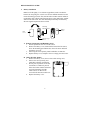
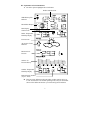
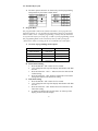
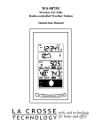
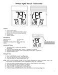
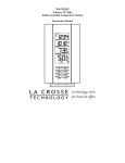
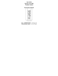
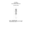
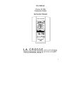
WS-8035
Wireless 433 MHz
Wireless Weather Station
Instruction Manual
TABLE OF CONTENTS
Topic
Inventory of Contents/ Additional Equipment
About WWVB
Quick Set Up Guide
Detailed Set Up Guide
Battery Installation
Start Up Sequence
Explanation of LCD Information
Function Key Layout
Program Mode
Overview of Programming Sequence
LCD Contrast Setting
Time Zone Setting
DST ON/OFF Setting
Radio-controlled Time ON/OFF Setting
12/24-hour Time Mode Setting
Setting the Time/Date Manually
Temperature Measuring Units (ºF/ºC)
Air Pressure Measuring Units (inHg/hPa)
Relative Pressure Setting
Forecast Sensitivity Setting
Features and Operation
Time Alarm Setting and Operation
Moon Phase
Minimum/Maximum Temperature/Humidity
Multiple Remote Temperature/Humidity Sensors
Comfort Icon
Weather Forecast and Pressure Trend Indicators
Weather Icons
Weather Tendency Arrows
Barometric Air Pressure Reading
Air Pressure History Bar Chart
Mounting
Maintenance and Care
Troubleshooting Guide
Specifications
Warranty Information
2
Page
3
3
4
5
6
7
8
8
8
8-9
9
9
9-10
10-11
11
11
11-12
12
13
14
14-15
15-16
16
16
17
17
18
18
19-20
21
22
23
24-25
INVENTORY OF CONTENTS
1. WS-8035—indoor weather station
2. TX4U—remote thermo/hygro
(temperature/humidity) sensor
3. Instruction manual and warranty card
ADDITIONAL EQUIPMENT (not
included)
1. Five fresh AA 1.5V alkaline batteries.
2. One wall-mounting screw (optional)
ABOUT WWVB (radio-controlled time)
The NIST (National Institute of Standards and Technology—Time and
Frequency Division) radio station, WWVB, is located in Ft. Collins, Colorado
and transmits the exact time signal continuously throughout the United States at
60 kHz. The signal can be received up to 2,000 miles away through the internal
antenna in the indoor weather station. However, due to the nature of the Earth’s
Ionosphere, reception is very limited during daylight hours. The indoor weather
station will search for a signal every night when reception is best. The WWVB
radio station derives its signal from the NIST Atomic clock in Boulder,
Colorado. A team of atomic physicists continually measure every second of
every day to an accuracy of ten billionths of a second a day. These physicists
have created an international standard, measuring a second as 9,192,631,770
vibrations of a Cesium 133 atom in a vacuum. For more information about
WWVB please see the NIST website at
http://www.boulder.nist.gov/timefreq/stations/wwvb.htm
3
QUICK SET-UP GUIDE
Hint: Use good quality Alkaline Batteries and avoid rechargeable batteries.
1.
2.
3.
4.
Have the indoor weather station and remote thermo/hygro sensor 3
to 5 apart.
Batteries should be out of both units for 15 minutes.
Place the batteries into the remote thermo/hygro sensor first then
into the indoor weather station.
(All remote thermo/hygro sensors must be started before the indoor
weather station)
DO NOT PRESS ANY BUTTONS FOR 15 MINUTES.
In this time the indoor weather station and remote thermo/hygro sensor will start
to talk to each other and the indoor weather station will show both the indoor
temperature and humidity and the outdoor temperature and humidity. If the
indoor weather station does not display all values after the 15 minutes please
retry the set up as stated above. After all values are displayed for 15 minutes
you can place your remote thermo/hygro sensor outdoors and set your time.
The remote thermo/hygro sensor should be placed in a dry, shaded area. The
remote thermo/hygro sensor has a range of 80 feet. Any walls that the signal
will have to pass through will reduce distance. An outdoor wall or window will
have 20 to 30 feet of resistance and an interior wall will have 10 to 20 feet of
resistance. Your distance plus resistance should not exceed 300 ft. in a straight
line.
NOTE: Fog and mist will not harm your remote thermo/hygro sensor but direct
rain must be avoided.
To complete the set up of your indoor weather station after the 15
minutes have passed please follow the steps in the Detailed Set Up
Guide.
Note: The remote thermo/hygro sensor transmits a signal every 3 minutes; after
the batteries have been installed, the indoor weather station will search for the
signal for a duration of 5 minutes. If there is no temperature reading in the
OUTDOOR LCD after 5 minutes, make sure the units are within range of each
other, or repeat the battery installation procedure.
4
DETAILED SET-UP GUIDE
I.
Battery Installation
Batteries will fit tightly. To avoid start-up problems, make sure that the
batteries do not spring free. Also be sure to insert alkaline batteries into the
remote thermo/hygro sensor first, then the indoor weather station. Initial set
up should be done with the remote thermo/hygro sensor and indoor weather
station in the same room. The units should be permanently mounted only
after the signal reception has been verified.
Mounting
Bracket/Recept
Battery
Cover
Rain
Cover
Thermo-Hygro
Sensor
A. Remote Temperature and Humidity Sensor
1. Pull the cylindrical rain cover off the sensor.
2. Remove the battery cover (located on the backside of the sensor,
above the mounting post and bracket). Press the arrow and slide
the battery cover off.
3. Observing the correct polarity install 2 Alkaline AA batteries.
4. Replace battery cover, and place rain cover snugly onto the sensor.
B. Indoor Weather Station
1. Remove the battery cover (the cover has white writing on it).
2. Observe the correct polarity, and
install three Alkaline AA batteries.
3. Do not press any buttons for at least
ten minutes. If a button is pressed
before the indoor weather station has
received information from the
TX4U sensor, no data will be
received from that sensor until reset.
4. Replace the battery cover.
5
II. Start Up Sequence
A. Initial Start
1. Immediately after the batteries have been installed, the indoor
weather station will sound a “beep”, and the LCD will completely
light up for a brief moment.
2. All information will then appear in normal mode, with “12:00” as
the default time and “TH.1” as the default date (2004 as the year).
3. The indoor temperature and humidity, and barometric air pressure
(as 29.91 inHg relative RH) will also be displayed.
4. There is a “satellite” icon that appears in the bottom portion of the
LCD, between the outdoor temperature and humidity — this icon
informs the user that the indoor weather station is looking for
signals from the remote thermo/hygro sensor. Within five minutes
the remote temperature and humidity should be displayed—if not,
remove batteries from all units and repeat battery installation, the
remote temperature sensor first, then the indoor weather station.
B. WWVB Reception
1. Once the batteries are installed in the Weather Center, it will
automatically search for the WWVB signal. If it receives a good
signal (which is unlikely during daylight hours in most locations),
the WWVB reception indicator (looks like a tower icon) will flash.
The indoor weather station requires five full minutes of good
reception to successfully capture the signal and set to the correct
hour, minute, second, month, day and year. If the signal reception
is not successful within ten minutes, the signal search will be
cancelled and will automatically resume every two hours until the
signal is successfully captured.
2. The signal is sent from Ft. Collins, Colorado only and is similar to
an AM radio signal. Atmospheric interferences such as storms,
sunspots, and even sunlight will cause the signal to not travel as
far.
3. To maximize reception, place the indoor weather station in a
window facing Colorado, at least six feet from any electrical
source (computers, televisions, refrigerators, etc.). Do not move
the indoor weather station while it is searching for the signal.
4. The time and date can be manually set. Once the signal is captured,
it will override any time and date set to the time zone selected.
5. Once the time and date are set, the indoor weather station will
conduct a search every night at midnight and correct to the
accurate time and date (Daylight Saving Time is automatic). If the
signal has been received in the past 24 hours, the reception
indicator will be displayed.
6
III. Explanation of LCD Information
A. The below picture highlights the LCD features.
Radio-controlled time
WWVB Reception
Indicator
Moon Phase Display
Date Display
Comfort Icon
Indoor Temperature
Humidity Display
Forecast Icon
Air Pressure Trend
Indicator
Barometric Air
Pressure
24-hour Air
Pressure History
Outdoor Temperature
Humidity Display
Remote Sensor Number
(Up to 3 Total)
B. There are many different modes the indoor weather station can be set
to. The LCD shown is the normal operating mode, and your actual data
shown will be different based on your local settings and conditions.
7
IV. Function Key Layout
A. The below picture shows the six function keys used in programming
and operation of your indoor weather station
V. Program Mode
The program mode is laid out in a manner that allows you to program each
function separately, or you can follow the instructions entirely to program the
indoor weather center. Complete programming is usually done for the initial
set-up, and will require you to skip step 1,2 and 3 of each programming section.
The programming mode can be exited at any time by either pressing the
“Snooze/CH” button, or waiting for the 15-second time-out to take effect.
A. Overview of programming mode sequence
1. LCD Contrast
4. Radio-controlled
Time ON/OFF
7. Minute
10. Date
13. Relative pressure
setting
2. Time Zone
5. 12/24-hour
time mode
8. Year
11. °F/°C
14. Forecast
sensitivity
3. DST ON/OFF
6. Hour
9. Month
12. inHg/hPa
B. LCD Contrast Setting
1. Press and hold the “SET” button for five seconds.
2. “lcd” will appear at the top of the display and a number will flash
next to it.
3. Press and release the “OUT/+” button to select the desired LCD
contrast setting.
4. Press and release the “SET” button to confirm the LCD contrast
setting and continue to the Time Zone setting
C. Time Zone Setting
1. Press and hold the “SET” button for five seconds.
2. “lcd” will appear at the top of the display and a number will flash
next to it.
3. Press and release the “SET” button once more to advance to the
Time Zone setting.
4. A number will flash to the left of the letter “h” at the top of the
display just below the time display.
8
5.
6.
Press and release the “+” button to select the desired time zone.
Press and release the “SET” button to confirm the Time Zone
setting and continue to the DST ON/OFF setting.
D. DST ON/OFF Setting
1. Press and hold the “SET” button for five seconds.
2. “lcd” will appear at the top of the display and a number will flash
next to it.
3. Press and release the “SET” button twice more to advance to the
DST ON/OFF setting.
4. “DST” will appear to the right of the Moon Phase display and
“ON” or “OFF” will flash above that.
5. Press and release the “OUT/+” button to select DST ON/OFF.
Note: Some locations (Arizona and parts of Indiana) do not follow Daylight
Saving Time.
6.
Press and release the “SET” button to confirm the DST ON/OFF
setting and continue to the Radio-controlled Time ON/OFF setting.
E. Radio-controlled Time ON/OFF Setting
1. Press and hold the “SET” button for five seconds.
2. “lcd” will appear at the top of the display and a number will flash
next to it.
3. Press and release the “SET” button three more times to advance to
the Radio-controlled time ON/OFF setting.
4. “RCC” will appear to the right of the Moon Phase display and
“ON” or “OFF” will flash above that.
5. Press and release the “+” button to select Radio-controlled time
ON/OFF setting.
6. Press and release the “SET” button to confirm the Radiocontrolled time ON/OFF setting and continue to the 12/24-hour
Time Mode setting.
F. 12/24-hour Time Mode
1. Press and hold the “SET” button for five seconds.
2. “lcd” will appear at the top of the display and a number will flash
next to it.
3. Press and release the “SET” button four more times to advance to
the 12/24-hour time mode setting.
4. “12h” or “24h” will flash to the right of the Moon Phase display.
5. Press and release the “OUT/+” button to select 12 or 24-hour time
mode.
Note: In 12h mode “PM” will appear to the left of the time during PM hours.
If the time is not within the PM hours nothing will be displayed. Be sure to set
the time to the correct AM/PM time to ensure automatic reception.
9
6.
Press and release the “SET” button to confirm the 12/24-hour time
mode setting and continue to the Hour setting
G. Setting The Hour Manually
The WWVB signal will override any manual set time and date information. The
time will be based on the time zone selected.
1.
2.
Press and hold the “SET” button for five seconds.
“lcd” will appear at the top of the display and a number will flash
next to it.
3. Press and release the “SET” button five more times to advance to
the Manual Hour setting.
4. The hour will begin to flash at the top of the display.
5. Press and release the “OUT/+” button to select the desired hour.
6. Press and release the “SET” button to confirm the hour setting and
continue to the Minute setting.
H. Setting The Minutes Manually
1. Press and hold the “SET” button for five seconds.
2. “lcd” will appear at the top of the display and a number will flash
next to it.
3. Press and release the “SET” button six more times to advance to
the Manual Minutes setting.
4. The minutes will begin to flash at the top of the display.
5. Press and release the “OUT/+” button to select the desired
minutes.
6. Press and release the “SET” button to confirm the minutes and
continue to the Year setting.
I. Setting The Year Manually
1. Press and hold the “SET” button for five seconds.
2. “lcd” will appear at the top of the display and a number will flash
next to it.
3. Press and release the “SET” button seven more times to advance to
the Manual Year setting.
4. The year will begin to flash to the right of the Moon Phase display.
5. Press and release the “OUT/+” button to select the desired year.
6. Press and release the “SET” button to confirm the year and
continue to the Month setting.
J. Setting The Month Manually
1. Press and hold the “SET” button for five seconds.
2. “lcd” will appear at the top of the display and a number will flash
next to it.
3. Press and release the “SET” button eight more times to advance to
the Manual Month setting.
4. The Month will begin to flash to the right of the Moon Phase
display.
5. Press and release the “OUT/+” button to select the desired month.
10
6.
K.
L.
M.
N.
Press and release the “SET” button to confirm the month and
continue to the Date setting.
Setting The Date Manually
1. Press and hold the “SET” button for five seconds.
2. “lcd” will appear at the top of the display and a number will flash
next to it.
3. Press and release the “SET” button nine more times to advance to
the Manual Date setting.
4. The date will begin to flash to the right of the Moon Phase display.
5. Press and release the “OUT/+” button to select the desired date.
6. Press and release the “SET” button to confirm the date and
continue to the Temperature Measuring Units setting.
Temperature Measuring Units Selection (°F or °C)
1. Press and hold the “SET” button for five seconds.
2. “lcd” will appear at the top of the display and a number will flash
next to it.
3. Press and release the “SET” button ten more times to advance to
the Temperature Measuring Units setting.
4. °F or °C will flash at the top of the display.
5. Press and release the “OUT/+” button to select the desired
temperature measuring unit.
6. Press and release the “SET” button to confirm the temperature
measuring unit and continue to the Air Pressure Measuring Units
setting.
Air Pressure Measuring Units Selection (inHg/hPa)
1. Press and hold the “SET” button for five seconds.
2. “lcd” will appear at the top of the display and a number will flash
next to it.
3. Press and release the “SET” button eleven more times to advance
to the Air Pressure Measuring Units setting.
4. inHg or hPa will flash at the top of the display.
5. Press and release the “OUT/+” button to select the desired air
pressure measuring unit.
6. Press and release the “SET” button to confirm the air pressure
measuring unit and continue to the Relative Pressure setting.
Relative Pressure Setting
1. Press and hold the “SET” button for five seconds.
2. “lcd” will appear at the top of the display and a number will flash
next to it.
3. Press and release the “SET” button twelve more times to advance
to the Relative Pressure setting.
4. The barometric air pressure will flash in the middle of the display,
just below the forecast icon
5. Press and release the “OUT/+” or “IN” button to select the
desired air pressure measuring unit.
11
6.
Press and release the “SET” button to confirm the relative pressure
setting and continue to the Forecast Sensitivity setting.
O. Forecast Sensitivity Setting
1. Press and hold the “SET” button for five seconds.
2. “lcd” will appear at the top of the display and a number will flash
next to it.
3. Press and release the “SET” button thirteen more times to advance
to the Forecast sensitivity setting.
4. The two air pressure tendency arrows will begin flashing on either
side of the forecast icon and a flashing number will appear under
the forecast icon.
5. Press and release the “OUT/+” button to select the desired
forecast sensitivity setting.
Note: Barometric air pressure is usually reported as “relative air
pressure”. This reading is based on the combination of absolute air
pressure and altitude. In general, an increase in altitude will result in a
decrease in air pressure. Relative air pressure will make readings in
nearby locations relative to each other to allow for proper forecasting.
The absolute air pressure reading in the Weather Center cannot be
calibrated, only the relative air pressure.
6.
Press and release the “SET” button to confirm the forecast
sensitivity setting.
THE MANUAL SETTING IS NOW COMPLETED
12
FEATURES AND OPERATIONS
A. Time Alarm Setting and Operation
1.
To set the time alarm:
a. Press and hold the ALM/DATE button for 5 seconds.
b. The alarm time will begin to flash to the right of the moon
phase.
c. Press and release the IN button to adjust the hour.
Note: When in the 12-hour mode and setting an alarm for a time
between noon and midnight, “PM” will appear to the left of the alarm
time.
d.
e.
Press and release the OUT/+ button to adjust the minutes.
Press and release either of the SNOOZE/CH buttons to
confirm the setting or wait for 20 seconds and the display will
automatically return to the normal mode.
2.
To activate the alarm:
a. Press and release the ALM/DATE button to toggle between the
alarm time and the day and date.
b. When the alarm time and alarm icon are showing to the right
of the moon phase the alarm is activated.
c. When the day and date are showing in the DATE LCD the
alarm is deactivated.
3.
To activate the snooze:
a. While the alarm is sounding press and release the
SNOOZE/CH button.
b. The snooze will be activated for 10 minutes. The alarm will
come back on after 10 minutes.
c. To deactivate the snooze function press and release any button
other than either of the SNOOZE/CH buttons.
13
B. Moon Phase
1.
There are 12 moon phases shown on the indoor weather station;
the white portion signifies the portion of the moon visible in the
sky. Thus, when the moon icon is all white, it is a full moon. The
indoor weather station is programmed with all moon phases from
the year 2003 until 2029.
New Moon
Full Moon
Small Waxing Crescent
Large Waning Gibbous
Large Waxing Crescent
Small Waning Gibbous
First Quarter
Last Quarter
Small Waxing Gibbous
Large Waning Crescent
Large Waxing Gibbous
Small Waning Crescent
C. Minimum and Maximum Temperature and Humidity
1.
Indoor Minimum and Maximum Temperature and Humidity
The indoor weather station automatically stores the minimum and
maximum indoor temperature and humidity. The minimum and
maximum values are updated automatically when a new minimum
or maximum is recorded, or until manually reset.
a.
b.
c.
From the normal display mode, press and release the “IN” key
once to view the indoor maximum temperature and humidity
(“MAX” will be displayed above the indoor temperature and
humidity).
Press and release the “IN” key again to view the indoor
minimum temperature and humidity.
Press and release the “IN” key again to return to the normal
mode (timeout of viewing minimum/maximum values will
occur if no keys are pressed for fifteen seconds).
Note: To reset the indoor minimum and maximum temperature
and humidity, first display the values you wish to reset (minimum
or maximum). Next press and hold the “SET” key for at least
three seconds. You will see then that the values will reset to the
current temperature and humidity and corresponding time.
14
2.
Outdoor Minimum and Maximum Temperature and Humidity
The indoor weather station automatically stores the minimum and
maximum outdoor temperature and humidity. The minimum and
maximum values are updated automatically when a new minimum
or maximum is recorded, or until manually reset.
a.
b.
c.
d.
From the normal display mode, press and release the
“OUT/+” key once to view the outdoor maximum
temperature and humidity (“MAX” will be displayed above
the outdoor temperature and humidity).
Press and release the “OUT/+” key again to view the outdoor
minimum temperature and humidity.
Press and release the “OUT/+” key again to return to the
normal mode (timeout of viewing minimum/maximum values
will occur if no keys are pressed for fifteen seconds).
Note: To reset the outdoor minimum and maximum
temperature and humidity, first display the values you wish to
reset (minimum or maximum). Next press and hold the
“SET” key for at least three seconds. You will see then that
the values will reset to the current temperature and humidity
and corresponding time.
D. Multiple Remote Temperature Sensors
The WS-8035 is able to receive signals from 3 different remote sensors.
These extra remote sensors can be purchased through the same dealer
as this unit. A TX4U will monitor the temperature and humidity, a
TX3U will monitor temperature and display the temperature on its
LCD, a TX3UP will monitor the temperature via a probe for measuring
soil or water temperatures and a TX6U will monitor the temperature
only.
Note: When setting up multiple units it is important to insert batteries
first into all the remote sensors, and in numeric sequence. Second
install batteries into the indoor weather station. Transmission
problems will arise if this is not done correctly and if the total time for
set-up exceeds 6 minutes
1.
Set Up of Multiple Units
a.
b.
c.
It is necessary to remove the batteries from all units currently
in operation.
Remove the battery covers to all remote sensors.
Place all remote sensors in a numeric sequential order.
15
d.
e.
f.
2.
In sequential order, install batteries following the same battery
installation procedures seen in Detailed Set-Up Guide section
of this manual.
Install batteries into the indoor weather station.
Follow the Detailed Set-Up Guide for programming and
operating instructions.
Viewing and Operating with Multiple Remote Sensors
a.
b.
c.
To view the temperature of a different remote sensor press and
release either of the “SNOOZE/CH” buttons. A shift from
one “boxed” number to the next should be observed in the
OUTDOOR LCD.
The minimum and maximum temperature of the additional
remote sensor can be displayed by pressing the “OUT/+”
button.
To reset the minimum and maximum temperature readings
press and hold the “SET” button for 3 seconds and that
temperature/humidity record for that remote sensor will be
reset only.
Each remote sensor will have its own minimum and maximum values
stored.
E. Comfort Indicator for Indoor Temperature and Humidity
1.
2.
3.
The comfort level indicator appears inbetween the indoor
tempearture and humidity.
The indicator will display a “happy-face” when the temperature is
between 68°F and 79°F (20°C and 25.9°C), and the humidity is
between 45% and 64%.
A “sad-face” will be displayed when the temperature and humidity
are outside the mentioned ranges.
F. Weather Forecast Icon and Pressure Trend Indicators
The weather forecasting feature is estimated to be 75% accurate, and is
based solely upon the change of air pressure over time. The WS-8035
averages past air-pressure readings to provide an accurate forecast—
creating a necessity to disregard all weather forecasting for 12-24 hours
after the unit has been set-up, reset, or moved from one altitude to
another (i.e. from one floor of a building to another floor). In areas
where the weather is not affected by the change of air pressure, this
feature will be less accurate.
16
1.
Weather Icons
a. There are 3 possible weather icons that will be displayed at
various times in the center of the indoor weather station.
i
b.
c.
d.
e.
f.
Sunny—indicates that the weather is expected to improve
(not that the weather will be sunny).
ii Sun with Clouds—indicates that the weather is expected to
be fair (not that the weather will be sunny with clouds).
iii Clouds with Rain—indicates that the weather is expected
to get worse (not that the weather will be rainy).
The weather icons change when the unit detects a change in
air pressure.
The icons change in order, from “sunny” to “sun with clouds”
to “clouds with rain” or the reverse.
It will not change from “sunny” directly to “clouds with rain”,
although it is possible for the change to occur quickly.
If the symbols do not change, the weather has not changed (or
the change has been slow and gradual).
The sensitivity of the change in foreacst icon is set by the user
in section F of the Detailed Set Up Guide.
G. Weather Tendency Arrows
Pressure trend
1.
2.
3.
4.
5.
6.
7.
arrow
Along with the forecast icon there
is a pressure tendency arrow.
There is one that points up (on the
left side of the LCD) and one that
points down (on the right side of
the LCD).
These arrows reflect current changes in the air pressure.
An arrow pointing up indicates that the air pressure is increasing
and the weather is expected to improve or remain good.
An arrow pointing down indicates that the air pressure is
decreasing and the weather is expected to become worse or remain
poor.
No arrow means the pressure is stable.
A storm can be expected if there is a drop of 4 hPa or more in less
than 6 hours. The clouds with rain icon will be displayed and the
tendency arrow that points down will be flashing—indicating the
storm warning feature has been activated. The flashing will stop
when the air pressure stabilizes or begins to rise.
17
H. Barometric Air Pressure Reading
1.
2.
3.
I.
The actual barometric air pressure is displayed directly under the
weather forecast icon
The relative air pressure is calibrated by the user through the
programming mode.
Please Follow the programming instructions in section F of the
Detailed Set Up Guide to set this feature.
Air Pressure History Bar Chart
1.
2.
3.
4.
5.
6.
7.
8.
9.
The bar graph shows in hPa (Hekto Pascal) the recorded air
pressure over the past 24-hours.
The horizontal axis shows the hours at increments of -24 hours, -18
hours, -12 hours, -9 hours, -6 hours, -3 hours, and 0 hours
(current).
The vertical axis is set by hPa: the “0” on this axis represents the
current hPa, and + or – 1,3,5, or 7 shows (in hPa) how high or low
the past air pressure was as compared to the current one.
The “0” on the vertical axis indicates the current air pressure value.
The “0h” on the horizontal axis indicates the current hour, thus the
current air pressure also.
Each bar on the bar graph represents a value of 0.03 hPa, and each
bar also has a corresponding value on the verticle axis.
Air pressure trends can be determined by simply glancing at the
bar graph.
a. If the bars are rising (higher on the right than the left) then the
air pressure has a rising trend, and the weather should
improve.
b. If the bars are dropping (lower on the right than the left) then
the air pressure has a falling trend, and the weather should
worsen.
Multiply the two values to find past air pressure (note the + or –
sign of values on the verticle axis); i.e. 0.03 hPa x 3 = 0.09 hPa,
now add this value to the air pressure (in LCD 4) to evaluate what
past air pressures have been.
The bar chart will constantly scroll to avoid burnout of the LCD.
Note: This feature cannot be turned off.
18
VII. MOUNTING
Note: Before permanently mounting, ensure that the indoor weather station is
able to receive signals from the sensors and WWVB signal at the desired
location. To achieve a true temperature reading, avoid mounting the remote
thermo/hygro sensor (or any sensor) where direct sunlight can reach the remote
sensor. We recommend that you mount the remote sensor on a North-facing
wall or under an eve. The sending range of the remote thermo/hygro sensor is
300-ft (100m) however obstacles such as walls, concrete, and large metal
objects can reduce the range. Place all units in their desired location, and wait
approximately 15 minutes before permanently mounting to ensure that there is
proper reception. If the indoor weather station loses the signal from the remote
sensor, it will display the last temperature reading for 15 minutes. After 15
minutes of not receiving any signals, the remote temperature will display “- -.-”.
A. Mounting the Remote Thermo/hygro Sensor
The remote thermo/hygro sensor can be mounted with the use of screws
or by using the adhesive tape.
1.
Mounting with screws
a.
b.
c.
d.
e.
f.
g.
h.
Remove the mounting bracket/receptor from the packaging.
Place the mounting bracket over the desired mounting surface.
Through the 2 screw holes of the bracket, mark the mounting
surface with a pencil.
Where marked, start the screw holes using the provided
screws.
Remove screws from the mounting surface.
Align the mounting bracket with the started screw holes.
Screw mounting bracket onto the mounting surface. The
screws should be flush with the bracket.
Fit the mounting post (on the back of the sensor) into the
receptor of the mounting bracket.
19
2.
Mounting with Adhesive Tape
a.
b.
c.
d.
e.
f.
With a nonabrasive solution, clean and dry the back of the
mounting bracket and the mounting surface to ensure a secure
hold. The mounting surface should be smooth and flat.
Remove the protective strip from one side of the tape.
Press firmly onto the designated area on the back of the
mounting bracket.
Remove the protective strip from the other side of the tape,
and situate the mounting bracket.
Firmly press the mounting bracket onto the mounting surface.
Fit the mounting post into the receptor of the mounting
bracket.
B. Mounting the WS-8035 Indoor Weather Station
The indoor weather station can be mounted in two ways; free standing
or hanging on a wall.
To have the indoor weather station free standing, simply unfold the
stands on the back and set on a stable flat surface.
To wall mount the indoor weather station;
1.
2.
3.
4.
Ensure that the integrated stands are folded in.
Fix a screw (not included) into the desired wall, leaving
approximately 3/16 of an inch (5mm) extended from the wall.
Place the indoor weather station onto the screw using the hanging
hole on the backside.
Gently pull the indoor weather station down to lock the screw into
place.
20
Maintenance and Care Instructions
A. Extreme temperatures, vibration, and shock should be avoided to
prevent damage to the units.
B. Clean displays and units with a soft, damp cloth. Do not use solvents
or scouring agents; they may mark the displays and casings.
C. Do not submerge in water.
D. Immediately remove all low powered batteries to avoid leakage and
damage.
E. Opening the casings invalidates the warranty. Do not try to repair the
unit. Contact La Crosse Technology for repairs.
21
TROUBLESHOOTING
Problem: The LCD is faint.
Solution: 1) Set the LCD contrast to a higher level.
2) Replace batteries.
Problem: No outdoor temperature/humidity is displayed.
Solution: 1) Remove all batteries, reinsert into the remote thermo/hygro sensor
first, then into the indoor weather station.
2) Place remote thermo/hygro sensor closer to the indoor weather
station.
3) Be sure all batteries are fresh.
4) No other interfering sources are being used (such as computer
monitors, TV sets, headphones, or speakers) in the vicinity. The
signal travels in a straight line, an electrical source near that “line”
may cause interference.
Problem: Temperature, humidity, or air pressure is incorrect.
Solution: 1) Check/Replace batteries.
2) If multiple remote sensors are in use, check location with
corresponding “boxed numbers.”
3) Move away from sources of heat/cold.
4) Adjust relative air pressure to a value from a reliable source (TV
radio, etc.).
5) The indoor weather station and remote sensors are calibrated at the
factory. If there is a consistent problem, please call La Crosse
Technology.
Problem: “- -” in humidity display.
Solution: 1) Humidity is below 1% or above 99%.
2) TX3U or TX3UP is used for remote temperature.
Problem: WWVB time and date will not set or update
Solution: 1) Wait until overnight for signal to be received
2) Move indoor weather station away from sources of electricity
3) Place indoor weather station in window facing Colorado
4) The first reception is most difficult, as the indoor weather station
needs five continual minutes of clear signal reception. After the
initial time/date set, the indoor weather station only requires one
full minute of clear reception each night.
22
SPECIFICATIONS
Indoor weather station
recommended operating
temperature
LCD contrast
Temperature measuring range
Indoor
32°F to 122°F (0°C to 50°C)
Outdoor
-21.8°F to 157.8°F with 0.2°F resolution
(-29.9°C to 69.9°C with 0.1°C resolution)
(“OFL” displayed if outside this range)
Relative humidity range
Indoor/Outdoor
Air pressure
Relative hPa (adjustable)
Relative inHg (adjustable)
Sensitivity setting hPa
Air pressure history
8 levels (0-7)
14.2°F to 139.8°F with 0.2°F resolution
(-9.9°C to 59.9°C with 0.1°C resolution)
(“OFL” displayed if outside this range)
1% to 99% with 1% resolution, indoor
weather station displays “--.-” if outside
this range
960 hPa to 1040 hPa
28.35 inHg to 30.72 inHg
2 hPa to 4 hPa
For the past 24 hours (0, -3, -6, -9, -12,
-18, and -24 hours)
Data checking intervals
Indoor temperature
Every 15 second
Indoor humidity
Every 20 seconds
Outdoor temperature
Every 5 minutes
Outdoor humidity
Every 5 minutes
Sensor reading update (within sensor)
Outdoor temperature
Every 1 minute
Outdoor humidity
Every 1 minute
Transmission frequency
433.92 MHz
Transmission range
300 feet (100m)
Power supply
Weather Center:
3 x AA (IEC LR6) 1.5V batteries.
Thermo Hygro Sensor:
2 x AA (IEC LR6) 1.5V batteries.
Dimensions (H x W x D)
Indoor weather station
Remote thermo/hygro sensor
10 x 7.75 x 1 inches
(254 x 197 x 25 mm)
4.29 x 1.56 x 0.78 inches
(110 x 40 x 20 mm)
23
WARRANTY INFORMATION
La Crosse Technology, Ltd provides a 1-year limited warranty on this product against
manufacturing defects in materials and workmanship.
This limited warranty begins on the original date of purchase, is valid only on products
purchased and used in North America and only to the original purchaser of this product. To
receive warranty service, the purchaser must contact La Crosse Technology, Ltd for
problem determination and service procedures. Warranty service can only be performed
by a La Crosse Technology, Ltd authorized service center. The original dated bill of sale
must be presented upon request as proof of purchase to La Crosse Technology, Ltd or La
Crosse Technology, Ltd’s authorized service center.
La Crosse Technology, Ltd will repair or replace this product, at our option and at no
charge as stipulated herein, with new or reconditioned parts or products if found to be
defective during the limited warranty period specified above. All replaced parts and
products become the property of La Crosse Technology, Ltd and must be returned to La
Crosse Technology, Ltd. Replacement parts and products assume the remaining original
warranty, or ninety (90) days, whichever is longer. La Crosse Technology, Ltd will pay all
expenses for labor and materials for all repairs covered by this warranty. If necessary
repairs are not covered by this warranty, or if a product is examined which is not in need or
repair, you will be charged for the repairs or examination. The owner must pay any
shipping charges incurred in getting your La Crosse Technology, Ltd product to a La
Crosse Technology, Ltd authorized service center. La Crosse Technology, Ltd will pay
ground return shipping charges to the owner of the product to a USA address only.
Your La Crosse Technology, Ltd warranty covers all defects in material and workmanship
with the following specified exceptions: (1) damage caused by accident, unreasonable use
or neglect (including the lack of reasonable and necessary maintenance); (2) damage
occurring during shipment (claims must be presented to the carrier); (3) damage to, or
deterioration of, any accessory or decorative surface; (4) damage resulting from failure to
follow instructions contained in your owner’s manual; (5) damage resulting from the
performance of repairs or alterations by someone other than an authorized La Crosse
Technology, Ltd authorized service center; (6) units used for other than home use (7)
applications and uses that this product was not intended or (8) the products inability to
receive a signal due to any source of interference.. This warranty covers only actual
defects within the product itself, and does not cover the cost of installation or removal from
a fixed installation, normal set-up or adjustments, claims based on misrepresentation by the
seller or performance variations resulting from installation-related circumstances.
LA CROSSE TECHNOLOGY, LTD WILL NOT ASSUME LIABILITY FOR INCIDENTAL,
CONSEQUENTIAL, PUNITIVE, OR OTHER SIMILAR DAMAGES ASSOCIATED WITH
THE OPERATION OR MALFUNCTION OF THIS PRODUCT. THIS PRODUCT IS NOT
TO BE USED FOR MEDICAL PURPOSES OR FOR PUBLIC INFORMATION. THIS
PRODUCT IS NOT A TOY. KEEP OUT OF CHILDREN’S REACH.
This warranty gives you specific legal rights. You may also have other rights specific to
your State. Some States do no allow the exclusion of consequential or incidental damages
therefore the above exclusion of limitation may not apply to you.
24
For warranty work, technical support, or information contact:
La Crosse Technology
2809 Losey Blvd. S.
La Crosse, WI 54601
Phone: 608.782.1610
Fax: 608.796.1020
e-mail:
[email protected]
(warranty work)
[email protected]
(information on other products)
web:
www.lacrossetechnology.com
FCC DISCLAIMER
This device complies with part 15 of the FCC rules. Operation is subject to the following two
conditions:
(1) This device may not cause harmful interference.
(2) This device must accept any interference received, including interference that may
cause undesired operation.
FCC ID: OMO-01RX (Receiver), OMO-01TX (sensor)
Freq. 433.92 MHz
La Crosse Technology
Made in China
WS-8035
All rights reserved. This handbook must not be reproduced in any form, even in excerpts, or
duplicated or processed using electronic, mechanical or chemical procedures without written
permission of the publisher.
This handbook may contain mistakes and printing errors. The information in this handbook is
regularly checked and corrections made in the next issue. We accept no liability for technical
mistakes or printing errors, or their consequences.
All trademarks and patents are acknowledged.
25