1
PRIPORT VT1730
Operating Instructions
-
MAJOR COMPONENTS
Machine Exterior
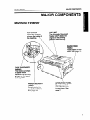
MAJOR COMPONENTS
Machine Exterior
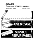
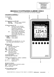
TOP COVER
Open this cover to
access the inside of
the machine.
\
A
I
-=x\
ADF UNIT
The Automatic Document
Feeder (ADF) feeds the
original to the printing
positiyn automati=lly.
\
this
15.
/
TAPE DISPENSER
(option)
This feeds out strips
of paper which
separate the printing
groups on the paper
delive~ table.
PAPER DELIVERY
TABLE
Completed prints
are delivered here.
See page 17.
OPERATION PANEL
Operator controls
and indicators are
located here. See
page 2.
Operation Panel
MAJOR COMPONENTS
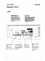
Operation Panel
=
Keys -
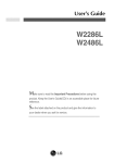
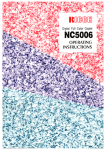
IMAGE MODE KEY
Press to select the Line
mode or Photo mode in
aocordanoe with the type
and quality of the original.
See page 35. \
SPEED KEY
Press to adjust the rotation
speed of the machine in
accordance with the type of
image and printing paper.
See page 27 and 28.
--
c
El
0(1
4
0(
7
0(
+
/
/
IMAGE DENSITY
KEY
Press to make
prints darker or
lighter. See page 27.
/
AUTO CYCLE KEY
Use to automatically
process masters and
make prints. See
page 30.
\
\
RESET KEY
Press to reset
error indicators.
IMAGE POSITION
KEY
Press to shift the
image forwards or
backwards on the
print paper. See
page 24.
Operation Panel
MAJOR COMPONENTS
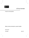
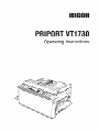
STOP KEY
Press to stop the machine. The
machine will continue printing when
the Print Start key is pressed. If you
stop making a master, the “~+
A“
indicators will blink and the machine
will not continue making the master
when the Master Making key is
MEMORY/CLASS KEY
Press to select group
printing. See page 31
and 33.
\
NUMBER KEYS
Press to enter the
numb~r of prints.
\
\
I
MASTER
~MAKING
KEY
Press to make a
master.
m
/
ENTER KEY
Press to input
information into
the memory.
CLEAR KEY
Press to change
the number that
is set in the
munter.
\
PROOF KEY
Press to make trial
prints or extra prints.
PRINT START KEY
Press to start printing.
INSTALLATION REQUIREMENTS
Machine Environment
INSTALLATION
Environments To Avoid
REQUIREMENTS
Machine Environment
The installation location should be carefully chosen because environmental conditions greatly
affect the performance of the machine.
Optimum environmental
Cl Temperature:
10-30
Cl Humidity: 20-90
conditions
‘C, 50 -86‘F
% RH
IJ On a strong and level base (for example, a sturdy desk).
Cl The machine must be level within 5 mm, 1/5” both front to rear and left to right.
Environments To Avoid
D Locations exposed to direct sunlight or strong light (more than 1,500 Iux).
D Locations directly exposed to cool air from an air conditioner or to heat from a heater.
(Sudden temperature changes from low to high or vice versa may cause condensation
within the machine.)
~ Dusty areas.
Cl Areas with corrosive gases.
Power Connation
INSTALLATION REQUIREMENTS
Access To The Machine
Power Connection
0 Securely connect the power cord to a dedimted
supplies more than 2.4A.
120V,60HZ
power source which
IJ Make sure the plug is firmly inserted into the outlet.
~ Avoid multiwiring.
Cl Do not pinch the power cord.
D Make sure that the wall outlet is near the machine and easily accessible.
~ Voltage must not fluctuate more than 10
?40.
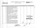
Access To The Machine
Place the machine near a power source, providing clearan=
as shown below.
Paper
Delivery Table
More than
60 cm, 23.7”
‘More than
60 cm, 23.7”
—
&
More than
70 CM, 27.6”
>
A
I
5
.
Supplying The Master Roll
SUPPLYING THE MASTER ROLL, INK, AND TAPE
.
SUPPLYING THE MASTER ROLL, INK,
AND TAPE
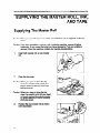
Supplying The Master Roll
Caution: When you open the top cover, make sure that there are no originals on the top
cover.
Caution: If you drop something, such as a clip, inside the machine, remove it before
continuing. If you cannot find what yOLJhave dropped or if you are unable to
remove it from the machine, contact your service representative.
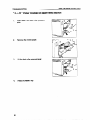
1.
Insert both spools into a new master
roll.
2.
Open the top cover.
Caution: When you open or close the top
cover, be careful not to pinch your
fingers between the top cover and
the back cover.
Caution: When you open or close the top
cover, be careful not to hit your head
or hands against the switch actuator
of the top cover.
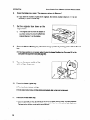
3.
6
Position the new master roll as shown
in the illustration.
..
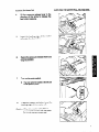
4.
Lift the pressure release Ieverin the
direction of the arrow to release the
feed roller pressure.
5.
Insert the leading edge of the master
roll under the feed roller.
6.
Return the pressure release lever to its
original position.
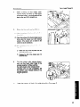
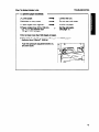
7.
Turn on the main switch.
O
8.
The main switch is located at the left side
of the operation panel.
Press the master cut button to cut the
leading edge of the master roll.
Caution: When the master cut button is
pressed, the master roll will rotate.
Do not touch the master roll.
.,
SUPPLYING THE MASTER ROLL, INK, AND TAPE
9.
Remove the cut-off
master roll.
~
portion of the
Removethe cut-offmasterpaper
completelyto preventmastermisfeed.
CJ If the masteris slackafter rotating,move
the pressurerelease lever severaltimes
to take up the slack.
10.
Close the top cover,
Supplying The Master Roll
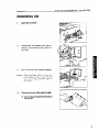
Supplying Ink
1,
Open the ink cover.
2.
Press down the release lever (green
tab [A]). The ink pack holder slides out
part way.
r=
I
3.
Pull out the ink pack holder as shown.
Caution: Take your finger off the release lever
while puliing out the ink pack holder.
You may be injured by the edge of
the ho/der.
Remove the cap of the new ink pack.
O
Do not remove the seal from the spout of
the ink pack.
5.
Install a ink pack as shown in the
figure.
5.
Slide in the ink pack holder.
6.
Press the setting lever (green tab [B])
until it clicks.
IJ
7.
If the setting lever is not pressed properly,
ink will not be supplied from the ink pack
to the machine.
Close the ink cover.
r
,
Suppiyl“ngTape For The Tape Dispenser (O@ion)
SUPPLYING THE MASTER ROLL, INK, AND TAPE
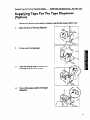
Supplying Tape For The Tape Dispenser
(Option)
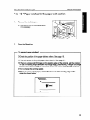
~ Make sure that the main switch is turned on and the tape power switch is off.
1.
Open the cover of the tape dispenser.
2.
Put the roll in the dispenser.
3*
Feed the leading edge of the roll into
the dispensing slot until it stops.
4.
Turn on the power switch of the tape
dispenser.
11
.,
SUPPLYING THE MASTER ROLL, INK, AND TAPE
5.
12
Press the manual cut button to trim off
the leading edge of the tape.
Supplying Tape For The Tape D~penser (Option)
OPERATION
Cautions For Printing Paper
OPERATION
Cautions For Printing Paper
Only use printing paper that meets the following specifications:
Size:
Max.: 216 mm x 356 mm, 8.5” x 14.0”
Min.: 90 mm x 140 mm, 3.5” x 5.5”
Weight:
70 g/rep -200
g/rep, 18.6 lb -53.2
lb
Print Area: 210 mm x 349.6 mm, 8.3” x 13.8” or less
Cautions:
IJ Avoid using the following kinds of paper:
= Roughly-cut paper
= paper of dmerent thicknesses in the same stack
= Buckled or curled paper
- Short grained paper
e paper of low stiffness
= Dusty paper
IJ Correct curls in the paper before setting it in the machine. When ou cannot correct
the paper curl, stack the paper with the curl face down. Othemise t x e paper may wrap
around the drum or stares may appear.
D Store paper where it will not curl or absorb moisture. Use paper smn
unpacked.
after it is
Cl Avoid using the top and bottom sheets of a new paper pack to prevent paper misfeeds
(multiple feeding).
Cl When thick paper is used, the paper tends not to be delivered properly if it is curled
or if the printing speed is at the lowest setting.
~ Only use paper where the leading edge has two right angle comers, as shown below.
tn
13
OPERATION
Cautions When Using The Document Feeder
Cautions When Using The Document Feeder
Only use originals that meet the following specifications:
Size:
Max.: 216 mm x 356 mm, 8.5” x 14.0”
Min.: 90 mm x 140 mm, 3.5” x 5.5”
Weight:
64 g/mz -104.7
g/mz, 17.0 lb -27.9
lb
Cautions:
IJ Remove paper clips or staples from the originals.
IJ If you use paste-up originals, make sure the pasted parts are adhered firml to the
base sheet. If the thickness of the paste-up original is more than 0.1 mm, 1250”,
a
Y
shadow may be printed on the paper.
fJ Correct curled or bent originals to prevent misfeeds.
~ If you use curled or folded originals, the image on the prints will be distorted, especially
for straight lines. The machine oannot correct curls or folds in originals.
IJ If there is a large solid fill ima e on the leading edge of the ori inal, paper misfeeds
tend to occur. In that case, shi 8 the image position backward wit\ the Image Position
key (See page 24).
~ For the following types of originals, make a copy and use the copy as an original.
C3carbon mated originals
= Bent or damaged originals
= Originals with glue on them
= Originals with binding holes
~ The first 5 mm, 1/5” of the leading ed e and the last 1 mm, 1/25” of the trailing ed e
cannot be printed. Make sure the lea 3 in edge margin is at least 5 mm, 1/5” and t! e
trailing edge margin is at least 1 mm, 1/ 8 5“.
5 mm
Original
1/5”
*
14
1 mm,
1/25”
Preparation For Printing
OPERATION
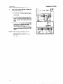
Preparation For Printing
ClWhen you load thick and small paper, see page 16.
Loading paper
1.
Open the paper feed table carefully.
2.
Adjust the paper feed side plates to
match the paper size.
3.
Press down the feed roller pressure
lever.
15
.,
Preparation For Printing
OPERATION
4.
Place the paper on the paper feed
table.
~
Make sure every sheet in the stack is set
evenly. This helps prevent paper skewing.
CJ Make sure the leading edge of the staok
is in full contact with the front board.
5.
0
500 sheets of paper can be loaded at a
time. If you load more than 500 sheets,
paper may not be fed properly.
~
Do not stack paper over the paper feed
side plates.
Lift the feed roller pressure lever.
Caution: Be careful not to catch your finger
between the /ever and the side paneL
6.
Make sure that the paper feed side
plates contact the paper gently.
O
The paper feed side plates should be
parallel to the sides of the paper stack,
othenvise the paper might not be fed
correctly.
Printing on thick and small paper
r
I
Set the side pads before adjusting the
paper feed side plates to match the
paper size.
l-m-
Thick and small paper:
Heavier than 150 g/mz, 39.9 lb
Smaller than
210 x 150 mm,
8.3” X 5.9”
11
LI -
J
,L3
II
II I
16
.. ..
Preparation For Printing
OPERATION
Setting up the paper delivery table
1.
Open the paper delivery table.
2.
Move the paper delivery end plate to
match the print paper size.
3.
Move the paper delivery side plates to
match the print paper size.
17
Preparation For Printhq
OPERATION
4.
Adjust the paper delivery rollers to
match the paper size,
D
Ifyoupositionthepaperdeliveryrollerson
lb
the print area, each roller will make a line
on the paper.
c
-&55iih
Cl You should leave margins of more than
5 mm, 1/5” on the rightand left sides of the
paper because the rollers track those
areas.
O
The paper delivery rollers may not feed
properly and a misfeed may occur if the
print contains a large solid fill image.
In such cases, leave margins of
approximately 10 mm, 2/5 on both edges
and move the rollersfurther away from the
edges.
Caution: Do not touch the paper delivery
rollers while the machine is
operating, or the machine will be
damaged.
)+
I
II
I
Standard Printing
OPERATION
Standard Printing
ClThe leading edge margin of the paper must be more than 5 mm, 1/5”, because if there
is no margm on the paper, the paper might be misfed, or might become di~. If there
is no margin on the original, adjust the image position by pressing the Image Position
key. See page 24.
~ Set the original straight. If you set the ori inal obliquely, the original will be fed obliquely
and the original image may be distorte 3 .
r
Important
The stack should not exceed 6 sheets of normal thickness paper.
I
Caution: While printing, do not move the paper delivery rollers. Otherwise, the drum maybe
damaged.
1.
Adjust the original guides to the size of
the original.
2.
Insert the original face down in the
ADF until it stops.
IJ *Do not insert different size originals at the
same time.
~
3*
The fed original may not be delivered
completely from the ADF until the next
original is fed.
Using the Number keys, enter the number of prints required.
fJ Up to 9999 prints can be entered at one time.
0 To change the number entered, press the Clear key and then enter the new number.
19
OPERATION
Standard Printinq
I
When you use larger than A4 or
81/2” x 11” size paper, set the original
tray extender.
4.
Press the Master Making key.
~ The original is fed, and a trial print is delivered to the paper delivery table.
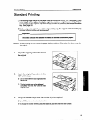
5.
Press the Proof key and check the image density and the image position. Use the Proof
key until the image density is stabilized.
D If the image position is not correct, adjust it using the Image Position key (See page 24) or the
side plate fine adjustment dial (See page 25).
6.
Press the Print Start key.
IJ After printing is completed, the same number of prints is automatically set for the next job.
H If the next original has been placed in the original table before the machine stops, that original
is fed automatically and a new master is made.
If you want to stop the machine during a print run, press the Stop key.
D The numtmr of prints set in the counter are made and the machine stops.
20
.. .
Standard Printing
7.
OPERATION
Remove the prints from the paper
delivery table.
D
If a large number of sheets is stacked in
the paper delivery table (approximately
400 to 500), the leading edge of the paper
tends to brush against this stack and may
be stained by the ink on freshly printed
sheets. Remove the paper from the paper
delivery table before that happens.
21
OPERATION
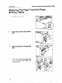
Restoring The Paper Feed And Paper Delivery Tables
Restoring The Paper Feed And Paper
Delivery Tables
1.
Turn off the main switch.
2.
Press down the feed roller pressure
lever.
3.
Remove the paper from the paper feed
table.
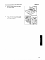
4.
Lift the feed roller pressure lever, then
return the paper feed table to its
original position.
5.
Move the paper delivery end plate to
its original position.
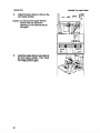
6.
Return the paper delivery table and the
original tray extender (if necessary) to
their original positions.
23
OPERATION
Adjusting The Image Position
Adjusting The Image Position
If the image position is not correct, adjust it before you start printing. Use the Image
Position keys after you have made the master.
The left and right Image Position keys shift the image about 0.6 mm, 1/40” each time
they are pressed. When the indicator changes, the image position shifts about 5 mm,
1/5”.
Shifting the image position forward or backward
1.
Press the right or left Image Position key.
D When you shift the image forwards, leave a margin (more than 5 mm, 1/5”) at the leading edge.
If there is no margin, paper may wrap around the drum and cause a misfeed.
2.
24
Press the Proof key. Check the image position.
OPERATION
AdjustingThe Image Position
Shifting the image to the right or left
1.
Press down the feed roller pressure
lever.
IJ
If you do not press down the feed roller
pressure lever, the top sheet of papermay
be misfed.
2.
If the top sheet of paper is caught by
the feed roller, remove the paper and
reinsert it. Then, lift the feed roller
pressure lever.
3.
Turn the side plate fine adjustment dial
as shown in the illustration.
I
I
CJ Before installingpaper, make sure that the
table is positioned in the center by
referring to the indicator.
O
The image position can be shifted up to
10 mm, 2/5” each way.
25
OPERATION
4.
Adjusting The Image Position
Adjust the paper delivery rollers to the
print paper position.
Caution: Do not touch the paper delivery
rollers while the machine is
operating, or the machine will be
damaged.
c
3>
WJ
1
5.
26
Adjust the paper delivery side plates to
the print paper position. Then check
the image position again.
(P--V
M
II
OPERATION
Adjusting The Image Density
Adjusting The Image Density
Before you make a master:
Use the Image Density key before
pressing the Master Making key.
Lighter
ma
9(D
HD
■
M
t
Darker
After you make a master:
Press the Speed key. To increase the speed, press the’~”
press the” < “ key.
key. To reduce the speed,
Cl The faster the printing speed becomes, the lighter the printing density is. If darker prints are
required, decrease the printing speed.
27
Changing The Printing Speed
Use the Speed key to adjust the rotation speed of the machine in accordance with the
image density and printing paper.
Press the Speed key. To increase the speed, press the ‘~~” key. To reduce the speed,
press the “ < “ key. The printing speed will be changed as follows:
.
Setting 1
Setting 2
Setting 3
70 sheets/minute
100 sheets/minute
130 sheets/minute
~ When the main switch is turned on, setting 2 is selected automatically.
28
To Stop The Machine During A Printing Run
OPERATION
To Stop The Machine During A Printing Run
If you want to stop the machine during a print run and print the next original, carry out
the following procedure.
1.
Press the Stop key.
2.
Set the new original.
3.
Re-enter the number of prints and press the Master Making key.
If you want to change the number of prints entered or if you want to check the
completed prints.
1.
Press the Stop key.
Change the number of prints or check the completed prints.
Cl To change the number of prints, re-enter the number using the Number keys after pressing the
Stop key.
2.
Press the Print Start key.
OPERATION
Making Master And Prints Automatically
Making Master And Prints Automatically
Use the Auto Cycle key to automatically process masters and make prints.
1.
Enter the number of prints required using the Number keys.
2.
Press the Auto Cycle key.
3.
Insert the original face down on the
original table until it stops.
4.
30
~
The stack should not exceed 6 sheets of
normal thickness paper.
O
The fed original may not be delivered
completely from the ADF until the next
original is fed.
Press the Master Making key.
OPERATION
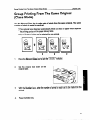
Group Printing From The Same Original (Class Mode)
Group Printing From The Same Original
(Class Mode)
Use the Memory/Class key to make sets of prints from the same original. The same
number of prints is made for each set.
D The optional tape dispenser automatically feeds out strips of paper which separate
the printing groups on the paper delivery table.
0 Up to 20 sets of prints can be selected for one original.
u
1.
Press the Memory/Class key to light the “~1~1~1” indimtor.
2.
Set the original face down on the
original table.
3.
With the Number keys, enter the number of prints for each set to be made from the
original.
4.
Press the Enter key.
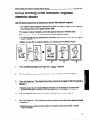
OPERATION
5.
Group Printing From The Same Original (Class Mode)
With the Number keys, enter the desired number of sets.
Cl The maximum number of sets that can be made is 20.
6.
Turn on the power Sw tch of the tape
dispenser (option).
7.
Press the Master Making key. Check the image position by making prints with the Proof
key.
IJ If the image position is not correot, adjust it using the Image Position key (See page 24) or the
side plate fine adjustment dial (See page 25).
8.
Press the Print Start key.
After the last page of each printingset is fed out to the paper delivery table, the tape dispenser
dropsa strip of paper onto the top of the paper stack. This marks the end of each printinggroup.
If the power switchof the optionaltape dispenser is turned off or the tape dispenser is not installed
in your machine, the group printingcycle stops after each group is finished. Remove the group
fromthe paper delivery table and press the Print Start key to start the next group printingcycle.
32
OPERATION
Group PrintingFrom Different Originals (Memory Mode)
Group Printing From Different Originals
(Memory Mode)
Use the Memory/Class key to make sets of prints from different originals.
~ The optional tape dispenser automatically feeds out strips of paper which separate
the printing groups on the paper delivery table.
D To prevent original misfeeds, do not set originals that are of different sizes.
~ The stack should not exceed 6 sheets of normal thickness paper.
ClThe fed original may not be delivered completely from the ADF until the next original
is fed in th= ADF.
IJ When you use thin or coated originals, you cannot use the Memory mode.
+
1.
Press the Memory/Class key to light the” ~~1~]”
2.
With the Number keys, enter the desired number of prints for the first original.
3.
Press the Enter key. This stores the number of prints to be made for the first original in
Memory 1.
indicator.
Cl When the number of printsin each printingset is the same, it is not necessary to inputthe number
of printsfor each group in memory. Do not follow step 4 and 5. Follow step 6, 7,8,9
and 10.
4.
With the Number keys, enter the number of prints for the second original.
5.
Press the Enter key. This stores the number of prints to be made for the second original
in Memory 2.
CJRepeat the above procedure for each original. The number of prints can be stored in memory
for up to 6 originals.
OPERATION
6,
Group Printing From Different Originals (Memory Mode)
Press the Enter key again. The memory returns to Memory 1.
0 If you store the number of prints for 6 originals, the memory number returns to 1. It is not
necessary to press the Enter key,
7.
Set the originals face down on the
original table.
0
8.
The originals are fed from the bottom of
the stack. Make sure that the originalsare
set in the correct sequence with the first
original (Memory 1) on the bottom.
Press the Master Making key. Cheek the image position by making prints with the Proof
key.
0 If the image position is not correct, adjust it using the Image Position key (See page 24) or the
side plate fine adjustment dial (See page 25).
9.
Turn on the power switch of the
optional tape dispenser.
10.
Press the Auto Cycle key.
~ The Auto Cycle indicator will light.
Cl In the Auto Cycle mode, printing starts automatically after a trial print is delivered.
11.
Press the Print Start key.
O After the last page of each printingset is fed out to the paper delivery table, the tape dispenser
drops a strip of paper onto the top of the paper stack if you have the optional tape dispenser.
The next group printing cycle begins automatically.
34
OPERATION
Photo Mode Printing
Photo Mode Printing
When printing a photograph or a color original, select the Photo mode.
D Moire patterns may occur when screened originals are printed.
Cl If you make print in the Photo mode at low temperature,
appear on the prints.
10
Press the Image Mode key to select the Photo mode.
2.
Press the Image Density key to adjust the image density.
3.
Follow the standard printing. See page 19.
light and dark stripes may
35
Thermal Head
DAILY MAINTENANCE
DAILY MAINTENANCE
Thermal Head
Clean the thermal head after every second master roll. Otherwise, white lines may
appear on the prints.
Caution: When you open the top cover, make sure that there are no originals on the top
cover.
Caution: If you drop something, such as a clip, inside the machine, remove it before
continuing. If you cannot find what you have dropped or if you are unab/e to
remove it from the machine, contact your service representative.
1.
Turn off the main switch and open the
top cover.
2.
Move the pressure release lever in the
direction of the arrow.
3.
Remove the master roll.
36
. ---- . .
..
Thermal Head
4.
While pushing out the platen roller
release levers (located on both sides
of the feed roller), grip both ends of the
feed roller and lift it straight up.
5.
Clean the thermal head as follows:
DAILY MAINTENANCE
(1) Wipe the surface of the thermal head with a
damp cloth.
(2) Clean the surface of the thermal head several
times using the cleaner pen with cleaning
solution. (The cleaner pen is stored in the
carton box as an accessory.)
(3) Dry the surface of thermal head with a clean
dry cloth.
~
Make sure to put the cap back onto the
cleaning solution bottle.
~
Replace the felt of the cleaner pen if it
becomes dirty.
6.
Grip the platen roller release levers,
and put the feed roller back in its
original position. While pushing
the right platen roller release lever
strongly until it is set completely, set
the platen roller release levers in its
original position.
7.
Place the master roll back in its original position. See page 6.
37
DAILY MAINTENANCE
Contact Glass
If you don’t clean the contact glass, black lines may appear on prints.
1.
Open the ADF cover.
2.
Wipe off the mntact glass with a dry
cloth .
3.
Close the ADF cover.
D
Make sure that the ADF oover is locked,
both at the right and left sides.
Contact Glass
Paper Feed Roller
DAILY MAINTENANCE
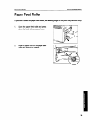
Paper Feed Roller
If you don’t clean the paper feed roller, the leading edge of the print may become dirty.
1.
Open the paper feed table and press
down the feed roller pressure lever.
2.
Wipe off paper dust on the paper feed
roller with almhol or cleaner.
I
u
l’ I
39
DAILY MAINTENANCE
Paper Delivery Rollers
Paper Delivery Rollers
If you don’t clean the paper delivery rollers, black lines may appear on the prints.
1.
Open the paper delivery table.
2.
Open the top cover.
3.
While rotating the drum manually,
wipe the paper delivery rollers with
alcohol or cleaner.
40
Exit Sensor
DAILY MAINTENANCE
Exit Sensor
If you don’t clean the exit sensor, misfeeds may occur in the paper exit section.
1.
Open the paper delivery table.
2.
Wipe the exit sensor with a dry cloth.
41
Drum Clamper
If you don’t clean the drum clamper, the master will not be set correctly around the
drum and the image position may not be consistent during a long printing run.
1,
Open the top cover.
2.
Wipe the drum clamper with a cloth
damped with water.
Cauth:
Never use alcohol or c/caner.
Otherwise, the drum clamper will be
damaged.”
TROUBLESHOOTiNG
TROUBLESHOOTING
If a malfunction or a misfeed occurs within the machine, the following indicators will blink or
light.
Monitors
When the Misfeed Indicator (~+) Lights
I
MONITOR
1%0o
1+0o
1+oo
+)+
+B
+C
1+0
o
I
I
I
I
+E
$~+F
1+:
+G
I
MEANING
I
WHAT YOU SHOULD DO
Original Misfeed
I
I
Remove the original.
Paper Feed Misfeed
Master Feed Misfeed
I
I
PAGE
45
I
Remove the misfed paper.
46
I
Remove the misfed master.
4a
I
Paper Wrap Misfeed
Remove the misfed paper.
49
Master Eject Misfeed
Remove the misfed master.
51
Delivery Misfeed
I
Remove the misfed paper.
I
53
r
Clearing misfed paper, master, and original
After removing misfed items, press the Reset key to reset error indicators Do not
turn off the main switch when removing the misfed items.
~
Caution:
Cl When you open the top cover, make sure that there are no originals on the top cover.
Cl If you drop something, such as a cli , inside the machine, remove it before continuing.
If you cannot find what you have CP
ropped or if you are unable to remove it from the
machine, contact your service representative.
0 Remove misfed paper without tearing it. Remaining bits of paper will cause more
misfeeds and may eventually cause a serious failure. If you tear the paper when
removing it, make sure to remove all the torn pieces.
43
TROUBLESHOOTING
When the Open Cover/Unit Indicator (~)
MONITOR
I
Lights
WHAT YOU SHOULD DO
Close the cover.
D*
PAGE
I
)
Close the paper delivery fence.
Set the master eject box.
~+A
I
I
Close the ADF oover.
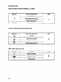
When the Supply/Exchange Indicators Light
MONITOR
&
la
1
&
h
WHAT YOU SHOULD DO
PAGE
Load paper.
Load a new ink catiridge.
55
Load a new master roll.
Empty the master eject box.
When Other Indicators Light
MONITOR
MEANING
M
Masternot wrapped.
Set the key oounter.
m
A
Set the original.
●
44
PAGE
56
When The Misfeed Indicator Lights
TROUBLESHOOTING
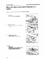
When The Misfeed Indicator (:+) Lights
“ :++ A “ Original
1.
Open the ADF rover.
2.
Pull out the original gently.
3.
Close the ADF rover mmpletely.
D
4.
Make sure that the ADF cover is locked,
both at the right and left sides.
Press the Reset key.
r
To prevent original misfeed:
~ Make sure that the ADF cover is closed.
~ Do not stack more than 6 sheets of normal paper.
~ Set the original straight.
IJ Push the original lightly when it is fed.
45
...-
When The Misfeed Indicator Lights
TROUBLESHOOTING
“ :++
1.
B
“ Paper
misfeed
in paper feed section
Push down the feed roller pressure
lever.
I
2.
Remove the misfed paper.
3.
Lift the feed roller pressure lever.
1
4.
Press the Reset key.
46
..
..
TROUBLESHOOTING
When The Misfeed Indicator Lights
—
To prevent paper misfeeds:
~ Curled paper.
Correct the curl.
IJ Wrinkled or wavy paper.
Do not use such paper.
Cl Paper edges stuck together.
Shuffle the paper.
~~>
IJ Paper smaller than 210 x 150 mm,
8.3” x 5.9” and heavier than
150 g/mz, 39.9 lb paper.
➤
Set the side pads.
See page 16.
D Do not load more than 500 sheets of paper.
~ Adiust the feed roller nressure when vou use thick ~aner
(h~avier than 150g/m2’,39.9 lb).
“
Push the pressure adjustment levers in,
and then down.
II
1
47
When The Misfeed Indicator Lights
TROUBLESHOOTING
“ :++
c
Warning:
“ MaSter
misfeed in master feed section
Be careful not to cut yourself on any sharp edges when you reach inside the machine
to remove misfed sheets of paper.
1.
Open the top cover.
2.
Lift the pressure release lever in the
direction of the arrow and remove the
misfed master.
3.
Reset the master roll. See page 6.
4.
Close the top cover.
5.
Press the Reset key.
48
When The Misfeed Indicator Lights
TROUBLESHOOTING
II :++ E “ Paper wrapping around the drum
Warning:
Be careful not to cut yourself on any shatp edges when you reach inside the machine
to remove misfed sheets of paper.
1.
Open the top cover.
2.
Peel the leading edge of the paper
away from the drum. Then, remove the
paper while rotating the drum
manually.
IJ
When you rotate the drum, be careful not
to hityour hands against other pans of the
machine.
3.
If you cannot find any paper, open the
paper delivery fence. Then, remove
the paper.
4.
Close the paper delivery fence and top
cover.
5.
Press the Reset key.
49
.-. .
TROUBLESHOOTING
—
When The Misfeed Indicator Liahts
To prevent paper misfeed:
D If there is a large solid fill image on the leading edge of original, set the original to
have its leading edge become the trailing edge. Alternative , change the image
position and make a margin of more than 5 mm, 1/5” at the 7eading edge of prints.
D Try to change the printing speed.
IJ When you set a curled paper, correct the face curl of the leading edge of the
paper as shown below.
“FeedDirection
Correct
*
50
When The Misfeed Indicator Lights
TROUBLESHOOTING
“:++Ft’
Master misfeed in the master eject section.
wrapped around the drum.
Warning:
Master
Be careful not to cut yourself on any sharp edges when you reach inside the machine
to remove misfed sheets of paper.
When a master misfeed occurs in the master eject section.
1.
Remove the master eject box.
0
Be careful not to drop the used master.
2.
Grasp the leading edge of the misfed
master and pull it out.
3.
Reinstall the master eject box.
4.
Press the Reset key.
51
TROUBLESHOOTING
When a master misfeed occurs on the drum.
1.
Open the top cover.
2.
As shown in the illustration, open the
drum ciamper, and grasp the leading
edge of the misfed master.
3.
Remove the misfed paper while
rotating the drum.
4.
Close the top cover.
5.
Press the Reset key.
52
When The Misfeed Indicator Lights
TROUBLESHOOTING
When The Misfeed Indicator Lights
“:% + G “ Paper misfeed in the paper exit section
1.
Remove
~
the misfed paper.
Open the top cover or paper delivery fence
if it is necessary.
2.
—
Press the Reset key.
To prevent paper misfeed:
#Check the position of the paper delivery rollers. See page 18.
Cl If the exit sensor is dim with paper dust, clean it. See page 41.
~ If there is a Iar e solid fill image on the leading edge of the original, set the original
so that its lea 3 mg edge becomes the trailing edge. Altemativel , change the Image
position and make a margin of more than 5 mm, 1/5” at the lea J ing edge of prints.
IJ Try to change the printing speed.
~ When you set a curled paper, mrrect the face curl of the leading edge of the
paper as shown below.
- Feed Direction
53
TROUBLESHOOTING
When The Open Cover/Unit Indicator Lights
When The Open Cover/Unit Indicator (~)
Lights
Make sure that the following covers and units are closed.
1.
Top cover
Close the top cover completely.
2.
Master eject box
Set the master eject box until it locks
in position.
3.
Paper delivery fence
Close the paper delivery fence.
~-+
A
ADF cover
Close the ADF cover completely, then
press the Master Making key.
54
TROUBLESHOOTING
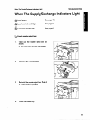
When The Supply/Exchange Indicators Light
When The Supply/Exchange
Indicators Light
fi
Load paper.
See page 15.
~
Load new ink cartridge.
See page 9.
&Load
See page 6.
new master roll.
~U Empty master eject box.
1.
Take out the master
shown.
eject box as
I
1
—
IJ Be careful not to drop the used masters.
W
2.
3.
:
Remove the used masters.
Reinstall
the master
eject box. Push it
in until it locks in position.
4.
Press the Reset key.
55
...
TROUBLESHOOTING
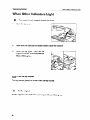
When Other Indicators Light
When Other Indicators Light
M – The master is not wrapped around the drum.
1,
Open the top cover.
2.
Make sure that there are no misfed masters inside the machine.
3.
Close the top rover. Then, set the
original in the ADF cover and press the
Master Making key.
$~[
–
~~
Set the key counter
The key counter (option) is not set. Insett the key counter.
A –
Set the original
Set the originals in the ADF before pressing the Master Making key.
56
TROUBLESHOOTING
Poor Printing
Poor Printing
Dirty background
If the background of prints are dirty, the
press roller inside the machine is dirty.
Make extra prints until the background
of prints bemmes clean.
IJ If you want to remove the press roller,
contact your sewice representative.
J
To prevent dirty backgrounds:
IJWhen ou use paper smaller than
1
originas.
~ When there is no margin on
the leading edge of the originals.
~
Change paper or originals.
~
Make a margin by pressing the
Image position key.
White lines/Black lines
Check the following parts and clean
them if dirty.
Contact glass (See page =.)
Thermal head (See page 36.)
57
.--—..
...
.
.
OPERATION NOTES
.
OPERATION NOTES
Cl Make sure to make a few trial prints to check the image position because the image position
of the trial print may not correspond with that of the original.
13The leading edge of the prints may become stained if the edge touches the image of the
prints on the paper delivery table.
ClWhen performing duplex printin , do not touch the printed paper for a while in order to let
the ink on the printed paper dry. 7f this is not done, feed roller marks will appear on the print
image.
CJIf the machine is not used for a long period, image density might decrease if the ink on the
drum dries. Make extra prints until the image density recovers.
D If the machine is not used for a long period, the master may not be e“ected automatically
because ink on the drum dries. In this case, remove the master aroun d the drum manually.
~ The ink of the print on the paper delivery table might stick to the back side of the next print.
~ Press the Proof key to make a test print, because the first few prints maybe light. Especially
in low temperature, you should make a few more test prints.
~ As various kinds and qualities of paper exist, some paper might wrap around the drum or
cause misfeeds.
Cl The ima e density varies according to the printing speed and the room temperature. In this
case, a 3Just the printing speed or increase the room temperature.
D Depending on the paper size or image osition, adjust the paper delivery rollers. When you
use normal originals, leave 5 mm, 1/ { “ margins on the right and left sides of the paper.
When you use dark originals, leave about 10 mm, 2/5” margins on both sides.
58
CAUTIONS
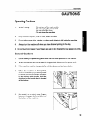
CAUTIONS
Operating Cautions
-Do
-Do
-Do
-Do
not
not
not
not
turn off the main switch.
unplug the power cord.
open the cover.
move the machine.
1.
While Printing:
2.
Keep corrosive liquids, such as acid, off the machine.
3.
Do not allow paper clips, staples, or other small objects to fall inside the machine.
4*
Always turn the machine off when you have finished printing for the day.
5.
Do not touch print paper if your fingers are wet or oily; fingerprints may appear on prints.
General Cautions
1.
Do not modify or replace any parts other than the ones specified in this manual.
2.
When the machine will not be used for long periods, disconnect the power cord.
3.
If the machine must be transported by vehicle, please contact your dealer.
4.
When the machine is transported,
make sure that the paper delivery table
is closed and never hold the machine
by the delivery table handle. Hold the
machine by the handle that is located
at tie bottom.
5.
Be careful no to pinch your fingers
between the paper delivery table and
the bottom of the machine.
59
.. . ... . ..
.. .
CAUTIONS
6.
Do not operate the machine with any rovers off.
7.
Be careful not to cut yourself on any sharp edges when you reach inside the machine
to remove misfed sheets of paper.
8.
Do not use thermal head cleaner for anything but cleaning the thermal head. Be careful
as this cleaner is flammable. Take note of the following cautions regarding the cleaner:
I=
Do not ingest.
= Do not inhale the cleaner’s fumes.
- Keepout of the reach of children.
= If cleaner comes in contact with your skin, wash well with water.
= Keep away from your eyes. If cleaner comes in contact with your eyes,
wash well. If irritation occurs, contact a doctor.
= Never
9.
placecleanerwhere it will be exposed to heat.
If your hands are stained with ink:
- Avoid prolonged or repeated contact with your skin.
= CIeanse your skin thoroughlyafter contact, before breaks and meals,
and at the end of your work period.
= Ink is readily removed from skin by waterless hand cleaners, followed
by washing with soap and water.
Also, be careful not to get any ink on your dothing while emptying the master eject
box or while loading a new ink cartridge.
60
SPECIFICATIONS
SPECIFICATIONS
Configuration:
Desk top
Printing”Process:
Full automatic one drum stencil system
Original Type:
Sheet
Original Weight:
64 g/mz -104.7
Image Mode:
Line/Photo
Original Size:
Max:
Min:
216 mm x 356 mm, 8.5” x 14.0”
90 mm x 140 mm, 3.5” x 5.5”
Paper Size:
Max:
Min:
216 mm x 356 mm, 8.5” x 14.0”
90mmx140
mm, 3.5” x 5.5”
Paper Weight:
70 g/mz -200
Printing Area:
210 mm x 349.6 mm, 8.3” x 13.8” or less
Print Speed:
70/1 00/1 30 cpm (3 settings)
First Print Time:
30 seconds ~ 2 seconds
Leading Edge Margin:
5 A 2 mm, 0.2” + 0.08”
Trailing Edge Margin:
I ~ 1 mm, 0.04” * 0.04”
Left Side Margin:
5-10
mm, 0.2”-0.4”
Right Side Margin:
5-10
mm, 0.2”-0.4”
Paper Feed Table
Capacity:
500 sheets (80 g/mz, 20.0 lb)
Paper Delivery Table
Capacity:
500 sheets (80 g~mz, 20.0 lb)
Master Eject Box
Capacity:
15 masters
ADF Original Capacity:
6 sheets or a 0.6 mm height
g/mz, 17.0 lb -27.9
g/mz, 18.6 lb -53.2
lb
lb
61
SPECIFICATIONS
Weight:
51kg,
l121b
Power Source:
120V 60Hz more than 2.4A
Power Consumption:
Master Making:
Printing:
Dimensions:
(W XDXH)
[Stored]
.
[Set up]
Noise Emission:
(Sound pressure level”)
●
= l%e measurements are
to be made according to
1s07779.
Optional Equipment:
less than 0.16 kW
less than 0.16 kW
692mmx612mmx440mm
27.2” X 24.1“ X 17.3”
1050mmx612mmx
UOmm
41.3” X 24.1“ X 17.3”
Less than 70 dB
Master Making:
54dB
70 cpm:
Printing:
100 cpm:
130 cpm:
62 dB
64 dB
68 dB
Key Counter, Tape Dkpenser
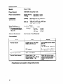
Consumables:
Name
Remarks
Size
Thermal master
Length:l 25 m, 410 ft/roll
Width: 240 mm, 9.5”
255 masters can be made
per roll.
Storage
-10-4O”C,1O-9OYORH
Ink
500 oo/pack
Environmental conditions:
-5”40”C,
IO”90%RH
Tape for tape maker
35 m, 114.8 R/roll
Thermal head cleaner
Cleaner pen -1 pc
Replacement felt -10
Cleaner bottle -1 po
ps
Cl Specifications are subject to change without notice.
62
Clean the thermal head
using the cleaner when 2
master rolls have been
used.
~