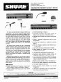
1
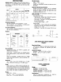
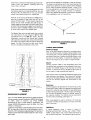
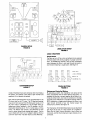
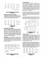
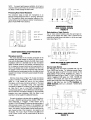
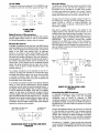
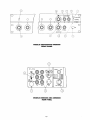
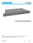
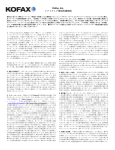
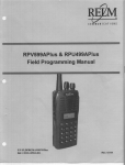
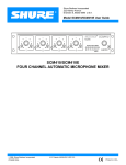
Shure Brothers lncorporated
222 Hartrey Avenue
Evanston, IL 60202-3696 U.S.A.
AMS4000 AND AMS8000 Installer's Manual
The Shure Automatic Microphone System [AMS] turns
microphones on and off [with automatic gating], greatly
reducing the reverberant sound quality and feedback problems often associated with the use of multiple microphones.
The special AMS microphones are gated on only by sounds
arriving from the front within their acceptance angle of
1 20°. Other sounds outside the 120° angle, including
background noise, will not gate the microphones on, regardless of level. In addition, the AMS adjusts gain automatically
to prevent feedback as the number of "on" microphones
increases.
w No threshold settings to misadjust
w Front-panel microphone channel gain controls and
Master control operate as in conventional mixers
w Selectable hold time keeps microphones on during short
pauses
w Preset or adjustable Off-Attenuation control for unob-
trusive gating
Automatic gain adjustment as additional microphones
gate on
The resulting sound is clearer than that of conventional
multiple microphone speech reinforcement and recording
systems-and free of the clipped and missed words, clicks
and pops, and noise pumping often associated with other
"automatic mixer" systems. Besides its major advantages
of simple setup and unmanned operation, the Automatic
Microphone System operates over an extremely wide
dynamic range without the possibility of threshold-setting
misadjustments.
w Wide, flat frequency response and low distortion up to
AMS Mixers are supplied in 4- and Schannel configurations [Models AMS4000 and AMS80001, each housed in a
single 3lh-inch rack-mount package. Both contain logic terminals [for channel muting, override functions, and gating indications], and link circuitry for expansion to as many as 2 0 0
linked channels.
w Four or eight special microphone inputs [for use only with
AMS Features:
w Reliable, quick-acting, noise-free gating-virtually insensitive to changes in sound source loudness or distance
w Smooth pleasant-sounding turnon and turnoff
characteristics
+ 18 dBm output
w Logic inputs and outputs enhance system versatility
w Linking capability for systems of as many as 2 0 0
microphones and 25 mixers
LED indication of gating operation and output level
w Automatic muting prevents annoying thumps and
loudspeaker damage when unit is turned on and off
AMS microphones] use standard two-conductor shielded
cables and three-pin connectors
w Balanced output switchable to line or microphone level
w Front- and rear-panel unbalanced Aux inputs and outputs
w Front-panel headphone monitor jack
w Direct [non-gated] outputs available from individual
microphones
w Underwriters Laboratories Listed and Canadian Stan-
dards Association listed as Certified
..... -......-.
Shure AMS4000 and AMS8000 Mixers are designed for use only with Shure AMS Condenser Microphones. Conventional condenser or
other microphones will not operate properly with the AMS4000 and AMS8000.
-
OCopyr~ght1997, Shure Brothers lncorporated
27A8273(QC)
Printed in U.S.A.
U.S. Patent 4,489,442; other patents pending
TABLE OF CONTENTS
General . . . . . . . . . . . . . . . . . . . . . . . . . . . . . . . . . . . . . . . . . . . . . . . . . . . . . . . . . . . . . 1
Specifications . . . . . . . . . . . . . . . . . . . . . . . . . . . . . . . . . . . . . . . . . . . . . . . . . . . . . . . 3
.
Connections. Controls and Indicators . . . . . . . . . . . . . . . . . . . . . . . . . . . . . . . . . . . . . 4
MicrophonePlacement . . . . . . . . . . . . . . . . . . . . . . . . . . . . . . . . . . . . . . . . . . . . . . . . . 6
Typical Applications . . . . . . . . . . . . . . . . . . . . . . . . . . . . . . . . . . . . . . . . . . . . . . . . . . . .6
ConferenceRoom . . . . . . . . . . . . . . . . . . . . . . . . . . . . . . . . . . . . . . . . . . . . . . . . . 6
Church . . . . . . . . . . . . . . . . . . . . . . . . . . . . . . . . . . . . . . . . . . . . . . . . . . . . . . . . . .6
Courtroom . . . . . . . . . . . . . . . . . . . . . . . . . . . . . . . . . . . . . . . . . . . . . . . . . . . . . 6.
Legislature . . . . . . . . . . . . . . . . . . . . . . . . . . . . . . . . . . . . . . . . . . . . . . . . . . . . . . 6.
LogicFunctions . . . . . . . . . . . . . . . . . . . . . . . . . . . . . . . . . . . . . . . . . . . . . . . . . . . . . . 8
.
CoughButton . . . . . . . . . . . . . . . . . . . . . . . . . . . . . . . . . . . . . . . . . . . . . . . . . . . 8
.
Chairperson-Controlled Muting . . . . . . . . . . . . . . . . . . . . . . . . . . . . . . . . . . . . . . .8
Disabling the Gating Function [Bypass] . . . . . . . . . . . . . . . . . . . . . . . . . . . . . . . . .8
Remote Channel-On Indication . . . . . . . . . . . . . . . . . . . . . . . . . . . . . . . . . . . . . . 8.
LoudspeakerMuting . . . . . . . . . . . . . . . . . . . . . . . . . . . . . . . . . . . . . . . . . . . . . . .8
"Filibuster"Mode . . . . . . . . . . . . . . . . . . . . . . . . . . . . . . . . . . . . . . . . . . . . . . . . . 9
Preventing Room Noise Modulation . . . . . . . . . . . . . . . . . . . . . . . . . . . . . . . . . . .9
.
MicrophoneLock-On . . . . . . . . . . . . . . . . . . . . . . . . . . . . . . . . . . . . . . . . . . . . . . 9
Diode Isolation of Logic Controls . . . . . . . . . . . . . . . . . . . . . . . . . . . . . . . . . . . . . . 9
External Logic Devices . . . . . . . . . . . . . . . . . . . . . . . . . . . . . . . . . . . . . . . . . . . .9.
15-VoltCMOS . . . . . . . . . . . . . . . . . . . . . . . . . . . . . . . . . . . . . . . . . . . . . . . . .10
.
Digital Controls or Microcomputers . . . . . . . . . . . . . . . . . . . . . . . . . . . . . . . . . 1
.0
.
WirelessMicrophones . . . . . . . . . . . . . . . . . . . . . . . . . . . . . . . . . . . . . . . . . . . 10
.
Direct Out Gating . . . . . . . . . . . . . . . . . . . . . . . . . . . . . . . . . . . . . . . . . . . . . . .10
Controlling Non-AMS Microphones . . . . . . . . . . . . . . . . . . . . . . . . . . . . . . . . . 11
.
OperatingHints . . . . . . . . . . . . . . . . . . . . . . . . . . . . . . . . . . . . . . . . . . . . . . . . . . . . 11
.
Phasing . . . . . . . . . . . . . . . . . . . . . . . . . . . . . . . . . . . . . . . . . . . . . . . . . . . . . . . I. 1
.
MicrophoneMuting . . . . . . . . . . . . . . . . . . . . . . . . . . . . . . . . . . . . . . . . . . . . . . 11
Grounding . . . . . . . . . . . . . . . . . . . . . . . . . . . . . . . . . . . . . . . . . . . . . . . . . . . . . .11
Internal Wiring Modifications . . . . . . . . . . . . . . . . . . . . . . . . . . . . . . . . . . . . . . . . . . 11
.
Troubleshooting . . . . . . . . . . . . . . . . . . . . . . . . . . . . . . . . . . . . . . . . . . . . . . . . . . . .15
.
Appendix I: Effects of Acoustic Environment on Gating . . . . . . . . . . . . . . . . . . . . . . 1 6
RoomNoise . . . . . . . . . . . . . . . . . . . . . . . . . . . . . . . . . . . . . . . . . . . . . . . . . . . . 1. 6
Reverberation . . . . . . . . . . . . . . . . . . . . . . . . . . . . . . . . . . . . . . . . . . . . . . . . . . 1. 6
TalkerDistanceandAngle . . . . . . . . . . . . . . . . . . . . . . . . . . . . . . . . . . . . . . . . 1. 6
Reflectivesurfaces . . . . . . . . . . . . . . . . . . . . . . . . . . . . . . . . . . . . . . . . . . . . . .1. 6
Appendix II: Theory of the Shure Automatic Microphone System . . . . . . . . . . . . . . 1 6
Appendix Ill: AMS Mixers and Conventional Microphones . . . . . . . . . . . . . . . . . . . . 17
1
WARNING
Voltages in this equipment are hazardous t o life . Refer all internal
wiring modifications and servicing t o qualified service personnel .
SPECIFICATIONS
Output Level [at full galn, 1 kHz, one channel gated On,
Off-Atten a t -1 5 , wlth AMS26 probe mtcrophone, output
terrnlnatlons: Llne 6000, MIC1500. Aux 50k. Olrect 50k,
Phones 20001
OUTPUT
INPUT
Lina
Mtcrophone + 1 5 8 dBV
lnput
[ + 1 8 dBrn]
Senstttv~ty
172 dB SPL tn]
Mic
Aux
Direct
Phonaa
Input Clipping
Leva1 a t IkHz
34
dBV
+ 17
5 6 dBV
-4 dBV
1 2 8 dB SPL
34
dBV
+I7
dBV
--
-4 dBV
+ 2 0 dBV'
dBV
--
Aux
Input
Senstttvlty
1-22 dBV ~ n ]
--
+ 1 5 8 dBV
+ 7 to
-
'Depend~ngon Aux control settlng
Frequency Response
Aux lnput t o Outputs: 3 0 to 20,000 Hz, * 2 dB
Mic In t o Outputs: 7 0 to 2 0 , 0 0 0 Hz, 2 dB [controlled low-frequency rolloff below 5 0 Hz]
*
Aux lnput Impedance
70k or greater, unbalanced [designed for use with less
than 10k source impedance]
Off-Attenuation
F~xed: -1 5 dB
Varlable -cx, to -8.5 dB
[Slngle mtxer; attenuation Increases as addltlonal mixers
are l~nked]
Overload and Shorting Protection
Shortlng the lnputs or outputs, even for prolonged
perlods, will cause no damage; m c lnputs wlll not be
damaged by slgnals up t o 3V; aux lnputs will not be
damaged by slgnals up t o 10V
Logic Terminals [all specifications referenced t o Logic
Ground terminals]
lnputs [Override, Mute]
High [inactive]: Greater than 1.9V [5.OV typical] [no
input current with 5 . 0 t o 20V applied]
Low [active]: Less than 1.9V [OV typical] [sources
80
when grounded]
MinlMax Applied Voltage: + 20V
Outputs [Gate]
High [inactive]: 5.OV in series with 10k resistance
[sources 0 . 2 mA with 3.OV output] [minlmax applied
voltage: -0.5 t o + 15V]
Low [active]: Less than 0.5V sinking [I
00 mA max]
Outputs
IMPEDANCE
OUTPUT
Deaigned for
Uw With
Mtc
150R balanced
ltnes
Llne
6 0 0 f l balanced
lhnes
Aux
10k or greater
atrect
Actual
[Internal]
Output
Clipping
bval
10-50k unbalanced
LOGIC EQUIVALENT CIRCUIT DIAGRAM
FIGURE 1
rno clrcutt
Phones
200n
Hum and Noise
Equivalent lnput IYoise: 2 7 dB SPL, A-weighted, with
AMS26 probe microphone
Output Noise: - 6 2 dBV [master up], -88 dBV [master
down] [300-20,000 Hz, input controls down, Off-Atten
at -1 51
Operating Voltage
105-13 2 Vac, 50160 Hz, 2 0 W [fused internally]. Can
be rewired for 210-264 Vac operation [see 240V
Operation]
Temperature Range
Operating: -29" t o 57°C [-20" to 135"FI
Storage: -29" to 7 1 "C [-20" t o 1 60°F]
Dimensions
See Figure 2
Output Hum and Noise: -58 dBV [master up], -79 dBV
[master down] [20-20,000 Hz, input controls down, OffAtten at -1 51
Distortion
THD 0.35% or less, 3 0 t o 20,000 Hz at + 1 5 dBm
output; IMD 0.5% or less up to + 1 5 darn output
Phase
Positive pressure on AMS microphone diaphragm produces positive voltage on pin 2 of LinelMic balanced output with respect t o pin 3, tip of Aux output, and tip and
ring of Headphones output, and negative voltage on tip of
Direct output. Aux output is in phase with Aux input.
Gating
Attack Time: 4 rnsec:
Hold Time: 0 . 5 or 1 .O sec [switchable]
Decay Time: 0 . 3 sec after Hold interval
OVERALL DIMENSIONS
FIGURE 2
Weight
AMS8000: 6.6 kg [I
4 Ib 8 oz]
AMS4000: 5 . 8 kg [I
2 Ib 13 oz]
AMSB000 [packaged]: 7.8 kg [I
7 Ib 4 oz]
AMS4000 [packaged]: 7.1 kg [I
5 Ib 9 oz]
Certifications
Listed by Underwriters Laboratories, Inc.; listed by
Canadian Standards Association as Certified
CONNECTIONS, CONTROLS, AND INDICATORS
[Paragraph numbers that follow refer t o pictorial views on
inside back cover .]
1 . Microphones: The Shure A M S Condenser
Microphones are designed specifically for use with Shure
Automat~c Microphone Systems, A M S 4 0 0 0 or
AMS8000 mixers Do not attempt to connect AMS
microphones to standard phantom-powered or
standard non-phantom-powered inputs; they will
not function properly.
The AMS microphones, in conjunction with the special circuitry of the AMS mixers, uniquely discriminate between
desired sounds that originate within their 12 0 " front acceptance angle and all other sounds. The desired sounds
from the front of a microphone are detected and cause
the microphone t o be gated on, transmitting its signal to
the mixer output. Sounds outside the acceptance angle
will not gate the microphone on. When a microphone is
"on" [accepting signals], it operates like a cardioid
microphone [or like a hemi-cardioid in the case of lowprofile microphones]. Each AMS microphone operates
completely independently in analyzing its own sound field
and deciding whether a sound source is within the front
acceptance angle.
Among available microphones are: a low-profile surfacemount model [AMS22], a gooseneck model for permanent mounting [AMS24], a probe model [AMS26] with a
front pop-filter grille, and a lavalier model [AMS28]. Due
to the reinforcement of sound waves from the adjacent
boundary surface, the sensitivity of the surface-mount
model is twice as high [ 6 dB more] as that of the probe
model. The gooseneck model is supplied with a cable, but
less connector.
The microphone connector is a standard 3-pin professional audio type [XLR]. Under most circumstances,
lengths of 1 5 0 meters [ 5 0 0 ft] or greater of good quality
2-conductor shielded microphone cable can be used as
extensions between the microphone and the AMS mixer
microphone input. The same conductor must be wired to
the same numbered pin at both ends of the cable t o ensure proper functioning of the units. The shield should be
connected to pin 1 at both ends of extension cables. Good
practice dictates that microphones and extension cables
be grounded only t o the AMS mixer chassis ground.
2. Microphone Inputs: The AMS mixer is supplied with
either four or eight microphone inputs per unit. The
microphone inputs are designed for use only with Shure
AMS microphones; the Mixer will not operate with other
microphones; and Shure AMS microphones will operate
properly only with AMS mixers. The microphone input
connector is a female XLR type.
3 . Microphone Channel Gain Control: When set to
the "0" posltlon [detented counterclockwise], the
mlcrophone is not permitted to gate on. Turning the control clockwise from this position permits the microphone
s
angle
to gate on ether for sounds within ~ t acceptance
or by a connection to the Override log~cterminal [see
descr~pt~on
of Logic Terminals below].
The Microphone Channel Gain control does not affect the
Dlrect Output level unless a jumper change has been
made for post-fader output as described in Paragraph 4
below.
4 D i r e c t Output: This provldes a non gated
microphone-level s~gnalfrom the mtcrophone Thls output
behaves ltke a conventtonal cardloid h~gh-impedance
mlcrophone output It can be converted to balanced low
Impedance using a line matching transformer [Shure
A95UI An unbalanced low Impedance mlcrophone level
can be obtalned by loadlng wlth a 100-ohm reslstor [conp sleeve]
nected t ~ to
The '/4-1nchphone jack 1s supplled w~redpre-fader so that
the output 1s not affected by the posttion of ether the indiv~dualChannel control or the Master control, even when
the Channel control IS In the counterclockwise detent
["O"] position
Each channel can be wlred post-fader by moving a jumper
on the input module board [see section on Internal
Mod~ficationsfor deta~ls]Thls change causes the level at
the Dlrect Output to follow the settlng of the Channel
control
5 . Channel LED Indicator: A yellow LED indicator above
the Channel control l~ghtswhen the mlcrophone is gated
on. The status of the Direct output is not related to the
LED.
6. Hold Time: This swltch determines how long the
microphone stays on after the user stops talklng. Thls
delayed turnoff br~dgespauses In speech and reduces unnecessary gatlng action. The 0.5-second posltion
minimizes microphone on-time, while the I .O-second
position bridges longer pauses.
For special applications, the 1 .O-second positron can be
increased to as long as 2 seconds by inserting a reslstor
[see Internal Modifications section for details].
7. Off-Attenuation: This switch determines the attenuatlon of microphones that are not gated on. It is unnecessary for "off" microphones to be totally off to galn
the benef~tsof automatic mix~ng.Keeping them slightly on
at all times contributes to smooth unobtrus~vegatlng actlon.
The -15 setting of the Off-Attenuation switch is
recommended for most applications. The Variable setting allows continuous adjustment of the OffAttenuat~onfrom minus infinity to -8.5 dB [-8 setting]
by the screwdriver-slot adjustment directly above the
switch. [See sections on Link Jacks and on Theory of
Operation for further Information on Off-Attenuation.]
8 . Power Cord: A 3-conductor cord and grounded plug
designed for connection to 1 2 0 Vac, 50160 Hz outlets
only. To modify the unlt for 240V, refer to the section
on Internal Modifications.
9. On-Off Switch:
Push-buttorr switch on the front
panel turns the power to the AMS mixer on and off.
10. Power-On LED: A green LED on the front panel
lights when the power is on.
1 1 . Normal LED: A yellow LED on the front panel above
the Power-On LED beg~nsto turn on when the line and
aux output levels are above approximately - 2 0 dBV
[I 00 mV].
1 2 . Overload LED:
A red LED flashes when the
LineIMic, Aux, and Phones outputs approach clipping. If
this light flashes on, turn down the Microphone Channel
controls of the channels in use or turn down the
Master control until the light stays out.
13. Aux Input: A
l/4 -inch unbalanced phone jack input on
both the front and rear panel of the AMS mixer,
suitable for Aux level and line level sources, such as
tape recorders or players or conventional mrxers. This
non-gated input is mixed with the combined microphone
signals to appear at the LineIMic, Aux, and Phones outputs.
14. Aux Control:
The position of this control determines the level of the Aux Input.
15. Master Control:
The position of this control determines the level of the combined microphone and aux
signals at the LineIMic, Aux, and Phones outputs.
1 6 . LineIMic Output: This male XLR audio connector
has switch-selectable levels: either low-impedance
balanced microphone level or 600-ohm balanced line
level. This output provides the combined gated
microphone and non-gated aux input signals.
1 7 . Aux Output: The '/4-inch phone jack outputs on the
front and back panels are intended for unbalanced Aux
or line level loads. This output also provides the combined gated microphone and non-gated aux input signals.
gates the channel off. The channel output drops to the
level set by the Off-Attenuation switch. The Mute function dominates Override when both are simultaneously
activated unless a jumper change is made so that
Overr~dedominates [see Internal Modification section
for details].
OVERRIDE IN: Applying a logic "low" to this terminal
[from a logic gate or a switch closure to ground] forces
the channei on. The mixer is supplied so that when both
Mute [described above] and Override of a channel are
activated, Mute dominates.
lnhibit Function: The Mute function can be altered
to lnh~bitby an internal jumper change for each
channel [see Internal Modifications section for
details]. After the change, a logic "low" at the Mute
In terminal prevents the channel from gating on if it
is off, but allows it to remain on if it is already on.
After the Inhibit modification, for certain specialized
applications a logic connection can be made between
a channel's Gate Out and its Mute In terminal.
IMPORTANT: To prevent high-frequency oscrllation, never connect a channel's Gate Out to its
Mute In unless the lnhibit modification has been
made.
1 8 . Phones Output: This %-inch phone jack is suitable
for most stereo or mono headphones with 2- or
3-circuit phone plugs. The signal at this output is identical t o that at the LineIMic output.
19. Logic Terminals: These four screw terminals are
LOGIC GND
MUTE I N
built into a female barrier block module that plugs into
a male connector on the rear panel below the Direct
Output jacks (Figure 31. The barrier block's plug-in
design ensures proper placement and simplifies terminal wiring by eliminating the need for soldering. Connections to these terminals are not necessary for basic
AMS operation, but allow the AMS mixer to perform
additional functions. Unshielded wire or multi-conductor cable is adequate for the connectors.
The logic levels are nomtnally 0 volts [low] and 5.0 volts
[htgh]; they are directly compatible with standard
5-volt logic families [including CMOS and TTL].
GATE OUT: This terminal follows the channel gating
and goes to logic "low'' when the mrcrophone is gated
on. Sufficient current-sinking capability is provided to
l~ghtexternally powered LED'S [see Logic Functions
sectlon for example].
LOGIC GROUND: The Logic Ground terminals of all
channels are connected together internally and are
dist~nctfrom the AMS aud~oground. All logic ground
connections should be made to these terminals. The
power supply ground of external logic circuitry should
be connected to the L.ogic Ground terminal of Channel
8 [or Channel 4 In 4-channel AMS mixers]. To avoid
sw~tch~ng
clicks, do not Interconnect the Log~cGround
with the audio, chassrs, or rack grounds.
MUTE IN: Applying a logic "low" to this terminal
[from a logic gate or a switch closure to Logic Ground]
AMS MIC IN
3
REAR-PANEL CHANNEL PLATE
FIGURE 3
20. Link Jacks: These rear-panel %-inch phone jacks
are used t o link up to 25 AMS mixers together to provide an input capability of as many as 200
microphones. To link mixers, use short I -conductor
sh~eldedcables with -inch phone plugs on both ends.
Plug a cable between the Link A Out jack of one mixer
and the Link A In jack of the next mixer; AND plug a
cable between the L~nkB Out jack of one mixer and the
Link B In jack of the next. Leave open the Link In jacks of
the first mlxer in the chain and the Link Out jacks of the
last mixer In the chain. Both the Link A and Link B jacks
of each mixer must be connected: A Outs to A Ins
and q Outs to B Ins. Use the Link jacks for l~nkingonly,
not for audio inputs or outputs.
IMPORTANT:
When uslng the logic term~nalson
linked mlxers, connect the Channel 8 Logic Ground terminals of each unit together. Switching clicks may
result if thts is not done.
When mixers are linked, the combined signals of all the
mlcrophones appear at the outputs [MicILine, Aux, and
Phones] of ALL the linked mixers. Thus, you can take
outputs from several mixers for a multiple feed.
Use as few microphones as necessary to pick up everyone.
The closer the microphones are to their sound sources, the
greater the loudness of the sound system before feedback
occurs. Each microphone should be at least 1 meter [ 3 f t ]
from the wall behind it, and at least 0 . 3 meters [Ift] from
objects behind it, such as large ashtrays or briefcases.
When using AMS28 Microphones, avoid acoustic feedback
from loudspeakers near the microphones.
However, an aux source connected to an AMS mixer is
heard at the outputs of that mixer only, NOT at the
outputs of linked mixers. For this reason, plug the aux
source into the mixer providing the audio output. If
multiple feeds are being used from linked mixers and it
is desired that the aux source appear in all, parallel the
aux source [using Y-adapter cables] t o the Aux inputs
of all the mixers used for the multiple feeds.
The Master Gain control on each linked mixer controls
the overail level at its own outputs of all the linked
mlcrophones and of its own Aux inputs. The OffAttenuation controls and the Normal and Overload
LED'S operate in the same way-they control and show
the status of the outputs from the mixer on which they
appear. The Hold Tlme switch on each mixer affects
only the microphones connected to that mixer.
MICROPHONE ACCEPTANCE ANGLE
FIGURE 5
TYPICAL APPLICATIONS
Conference Room
Refer t o the AMS Operators Manual for microphone placement at conference tables. Connect extension cables t o the
microphones and to the microphone input connectors on the
rear panel of the mixer. Connect the LineIMic Output t o the
line input of the PA amplifier. To record the meeting, connect the Aux Output to the aux Input of a tape recorder.
Church
Connect extension cables to the microphones and t o the
microphone input connectors on the rear panel of the mixer.
Connect the LineIMic Output to the line input of the PA
amplifter. To record the service, connect the Aux Output to
the aux input of a tape recorder [see Flgure 61.
Note that the cholrs are inslde the acceptance angles of the
pulpit and lectern microphones. Thus, some choir members
may gate on the pulpit and lectern mlcrophones occasionally.
This will not seriously degrade the performance of the
system.
TO AMPL,
TAPE REC, ETC
LINKING MIXERS
FIGURE 4
MICROPHONE PLACEMENT
Use Low-Profile AMS22 Microphones on tables and desks;
use permanently mounted Gooseneck AMS24 Microphones
on tables, desks or lecterns; use Probe AMS26
Microphones on floor or desk stands or goosenecks; use
Lavalier AMS28 Microphones where the talker must have
freedom of movement.
Locate the microphones so that intended sources are within
60° of either side of the front of the microphone; that is,
within the 120° acceptance angle [see Figure 51. Sources of
undesired sound should be located outside the 120° acceptance angle.
Courtroom
Connect equipment as described for the church setup. Also
connect each Direct Output to a separate microphone input
channel of a multitrack tape recorder for easy identification
of talkers during transcription. The Aux Output containing a
mix of all the microphones connects to another channel of
the mult~trackrecorder. Th~schannel can be monitored to
hear the entire proceedings. [See Figure 71.
Often a tape playback 1s used for evidence or for transcript
ver~f~cation.
Connect the tape player's aux output to the Aux
lnput of the mixer.
Legislature
A typical legislature setup is shown in Figure 8 .
[Chairperson-Controlled Muting-see
LOGIC FUNCTIONS-is also shown.] Two or more mixers are linked via
the L~nkA and Link B jacks. The Channel 8 Logic Ground ter-
ALTAR
oMUTING
l
SWITCH
0
CHAIRPERSON*^
CHANNEL
ma
RECORDER
CHURCH SETUP
FIGURE 6
LEGISLATURE SETUP
FIGURE 8
LOGIC FUNCTIONS
Cough Button
The user can turn off his or her microphone [to the selected
Off-Attenuation level] during coughing or private conversations. To establish this function, wire an SPST pushbutton
switch between the Mute In and Logic Ground terminals on
each channel requiring a cough button. See Figure 9.
0
GATE OUT
L O G I C GROUND
MUTE IN
r*i
PLAYER
$GK-~
COURTROOM SETUP
FIGURE 7
minals of the linked mixers are connected. One mixer feeds a
PA system, and another mixer feeds a tape recorder and
equipment for a television broadcast.
Note that the Off-Attenuation can be set differently for the
PA mixer than for the TV mixer. The Ti/ feed and recorder
may sound more natural if the Off-Attenuation is set at -8 if
the room noise is sufficiently low. On the other hand, for
highest gain before feedback in the PA amplifier, the OffAttenuation should be set at -15 or, in some cases, at minus
infinity. The Master Gain control is set differently on each
mixer to obtain proper levels feeding each system. The aux
source feeds both mixers via a Y-adapter cable but the Aux
control on each mixer may also need to be set differently.
COUGH BUTTONS
FIGURE 9
Chairperson-Controlled Muting
By activating a switch, the chairperson can silence all the
other microphones and be heard without interruption. To
establish this function, connect together all the Mute In terminals of all the mixers, but make no connection t o the logic
terminals of the chairperson's microphone channel. Wire an
SPST pushbutton or toggle switch between the Mute In and
Logic Ground terminals of any one channel except the
chairperson's channel. See Figure 10.
The Chairperson-Controlled Muting feature is also illustrated
[see Figure 81 as part of a large system for a legislature.
Note that the Logic Ground terminals of both mixers are
connected, and that the chairperson's logic channels are unconnected.
0/
0
0
1
GATE OUT
LOGIC GROUND
M U T E IN
OVERRIDE IN
CcHAIRPERsoN7.s
CHANNEL
CHAIRPERSON-CONTROLLEDMUTING
FIGURE 10
Disabling the Gating Function [Bypass)
To keep all the microphones on, wire all the Override In terminals together to a Logic Ground terminal [see Figure 1 I ] .
This is useful if i t is desired t o bypass the automatic functioning and use the AMS mixer as an ordinary mixer.
Loudspeaker Muting
In some applications, a loudspeaker is located near each
talker to provide audio reinforcement or t o allow monitoring
of a telephone conversation or conference. Each
loudspeaker can cause feedback unless i t is automatically
switched off whenever the talker near i t speaks. To provide
this function, connect the Gate Out terminal of each channel
t o a separate loudspeaker muting relay as shown in Figure
1 3. Recommended relays are Guardian 1345-1 5 1 2 0 or
1475-1 C-120, or Potter & Brumfield R50-E2-YI-l2V or
R10-El -Y2-V185, or equivalent.
Each loudspeaker should be placed behind its associated
microphone to prevent the loudspeaker from gating on the
microphone. The loudspeaker volume should be low; otherwise the microphone may not gate on reliably when the
talker speaks.
If the existing sound system uses 24-volt relays, they can be
driven with the AMS Gate Out using internal wiring modifications described in the Internal Wiring Modifications section.
GATE OUT
LOGlC GROUND
M U T E IN
POWER
OVERRIDE I N
GATING BYPASS
FIGURE 11
Remote Channel-On Indication
The LED's above each Channel control light when that channel is gated on. These indicators can be used t o identify the
talker or to indicate t o each talker when his or her
microphone is on. To provide Channel-On indicators at locations remote from the mixer, connect LED's and a 5-volt
power supply t o the Gate Out terminals as shown in Figure
1 2 . NOTE: To avoid switching clicks in the audio outputs,
do not ground the power supply negative terminal t o the
audio system ground or rack ground.
IMPORTANT: If a single cable is to carry the AMS microphone audio signal and the dc power for the LED, separate
shielded pairs must be used. Failure to carry the dc power
on a shielded pair may result in audible clicking due to
capacitive coupling between the dc power lines and the
AMS microphone lines.
R= 1 5 0 - 3 0 0 n
i
GATE OUT
LOGlC GROUND
MUTE IN
OVERRIDE
IN^
LOUDSPEAKER MUTING
FIGURE 13
F:gR
AMPLIFIER
"Filibuster" Mode
In normal operation, when several people talk, all their
microphones gate on so that no speech is missed. But with
the mixer wired for "Filibuster" action, a microphone that is
gated on prevents other microphones from gating on. Once
a microphone is on, other microphones cannot gate on until
the talker has paused long enough so that his or her
microphone has gated off. Thus, the person talking has the
floor and cannot be interrrupted.
To establish this function, perform the internal Mute t o Inhibit jumper change [see Internal Modifications section for
details]. Then connect all the Mute In terminals of the
modified channels together; connect all the Gate Out terminals of the modified channels together, and connect the
Gate Out terminal of one modified channel t o the Mute In
terminal of another modified channel [see Figure 141.
0VERRIDE.IN
SUPPLY
GATE OUT
LOGlC GROUND
M U T E IN
OVERRIDE IN
REMOTE CHANNEL-ON INDICATORS
FIGURE 12
FILIBUSTER" MODE
FIGURE 14
NOTE: To prevent high-frequency oscillation, do not wire a
channel's Gate Out terminal to its own Mute In terminal until
the Mute to Inhibit change has been made.
GATE OUT
LOGlC GROUND
Preventing Room Noise Modulation
This connection keeps at least one microphone on to
eliminate varying background noise or "pumping" [see Figure
151. The channel to which the transistor collector is connected will be turned on whenever all other microphones are
gated off [see AMS Theory section].
M U T E IN
O V E R R I D E IN
MICROPHONE LOCK-ON
[ONE CHANNEL SHOWN]
FIGURE 16
GATE OUT
LOGlC GROUND
M U T E IN
OVERRIDE IN
Diode Isolation of Logic Controls
Two or more control functions using the same logic terminals can be isolated with diodes. Here a channel can be
muted by an overall group mute switch, or by its own cough
button [see Figure 1 71.
G A T E OUT
L O G l C GROUND
MUTE I N
OVERRIDE IN
ROOM NOISE MODULATION PREVENTION
FIGURE 15
Microphone Lock-On
The circuit described in the preceding paragraph can be
expanded using diode isolation to perform a new function.
Even with the advantages offered by the AMS, there may be
installations where it is desirable that the last microphone
gated on should remain on until another microphone turns
on. For instance, the sound reinforcement requirements of a
church may dictate that an altar microphone remain on as
the minister moves outside the acceptance angle. Normally
the AMS would not remain gated on after the initial hold time
elapsed if the minister continued to speak outside the acceptance angle.
With the circuit shown in Figure 16, the last microphone
to gate on remains on indefinitely. When a new microphone
gates on, it will release the lock-on for the previous
microphone, and the new microphone will lock on. The result
is the ultimate in automatic mixing: each logic-wired
microphone is capable of remaining on until no longer needed. Note that if two or more AMS microphones are
simultaneously gated on, normal AMS action will take place.
Since at least one microphone is always on, this circuit also
prevents room noise modulation. Bath the Mute In and
Override In remain usable for additional functions.
For each microphone to be given lock-on capability, the circuit uses a 2N2222 general-purpose amplifier NPN transistor [Motorola], a I-megohm, %-watt resistor, and a
number of 1N4148 diodes [GE] equal to the total number of
AMS channels involved. For instance, if the installation has
five AMS channels to be wired, a circuit containing one transistor, one resistor, and five diodes must be constructed for
each channel [a total of five transistors, five resistors, and
25 diodes]. The circuit in Figure 1 6 shows only one lock-on
circuit; similar circuits must be constructed for all lockan
channels.
D= I N 4 1 4 8
OR EQUIVALENT
GROUP
MUTE
f
COUGH B U T T O N S
DIODE ISOLATION OF LOGIC CONTROLS
FIGURE 'I7
External Logic Devices
The AMS logic levels are directly compatible with TTL and
5-volt CMOS logic families. The following example [Figure
181 uses logic gates t o perform the same function as the
diode isolation of logic controls. Suggested T L , LSTTL, or
CMOS NAND gates in Figure 18 are I/2-7420,74LS20 and
74C20. Suggested AND gates are 7408, 74LS08 and
74C08. In the example, the output of the Channel-On indicator goes to logic High if any channel gates on. [For information on logic gate use, see the TTL Cookbook and
CMOS Cookbook, both by D. Lancaster, Howard Sams
Publishing Co.]
-GATE OUT
c3
NAND GATE
0
+3
MUTE IN
0
-
EXTERNAL LOGIC DEVICES
FIGURE 18
0
15-Volt CMOS
The logic terminals can be used with 15-volt CMOS if a pullup resistor is used with each Gate output [see Figure 191.
LOGIC GROUND
The logic circuit for direct'
out gating is shown in Figure 21 .
IG
I
All resistors are 114 watt, and the opto-isolator can be a
Vactec VTL5C2 or VTL2C2, or a Shure 86A8900. The
50k to 100k resistor is optional; it will provide a finite OffAttenuation capability.
MUTE IN
OVERRIDE IN
15-VOLT CMOS
FIGURE 19
Digital Controls or Microcomputers
The AMS mixer logic terminals can interface with customdesigned digital control circuitry or even a microcomputer
for unlimited possibilities of system control functions.
Wireless Microphones
A wireless microphone can be used with the AMS [without
automatic gating], but its connection may be made in several
ways. If the microphone has a line-level output, connect that
output to the AMS mixer auxiliary input. An alternate
method is to connect a short jumper between the Logic
Ground and Override In logic terminals of the channel that
will contain the wireless microphone. With this channel permanently gated on, the balanced microphone-level output of
the wireless microphone receiver can be connected to the
channel input. [If the receiver has only a balanced line-level
output, the same connections can be made, but a line attenuator such as Shure's A15LA should be used in the
receiver-mixer line.]
The wireless microphone can be switched on and off remotely by grounding both the Mute In and Override In logic
terminals, and putting a switch in the circuit from the Mute
In terminal to ground. Since the Mute In circuit has
precedence over the Override In circuit, the microphone can
be controlled by this in-line switch.
If the wireless microphone receiver has a balanced line-level
output, a circuit can be constructed to use the wireless
microphone and still retain the automatic gating function. In
the diagram shown below [Figure 201, the value of resistor
R can be determined as follows. Start with a 2-megohm
resistor; at this value, the channel will not gate on until it
receives a signal of at least 0.01 6 volts [-36 dBV]. All AMS
logic terminals operate normally with this circuit. The gating
threshold can be varied by using a different resistor value according to the needs of the installation. Note that the
threshold is raised by a higher resistor value [more voltage is
required to overcome the threshold].
WIRELESS RECEIVER
LINE LEVEL OUTPUT
FROM
Direct Out Gating
The AMS mixer Direct Out jacks can be converted to direct
gated outputs so that the level and equalization of each
microphone can be controlled by a studio mixing console.
Automatic gain adjustment [based on the number of gatedon microphones] is out of the circuit-the decay time is
slightly decreased below the normal 0.3-second interval.
TOAMS MIXER
MIC INPUT
MICROPHONE INPUT TO GATING LlNE INPUT
FIGURE 20
Note that if a gated mixed output is not needed for the
modified channel, that channel's internal circuitry can be
modified rather than using the logic terminals. In this manner, the level control and decay characteristics can be retained, and the need for a separate power supply eliminated.
[IMPORTANT: This conversion removes each modified
channel from the AMS main mix bus, so that it operates independently of the unmodified channels. In other words, the
automatic gating function is retained, but the automatic mixing is not.] Refer to the InternalWiring Modifications section
for further information.
DIRECT
GATED
OUT
(AUX/HIZ
MIC LEVEL)
OUT
300
+5v
POWER
SUPPLY
GATE OUT
LOGIC
GROUND
MUTE IN
OVERRIDE
IN
DIRECT OUT GATING USING LOGIC
FIGURE 21
Controlling Non-AMS Microphones
If it becomes necessary to use a conventional [non-AMS]
microphone in an AMS system and the non-gated
microphone must be turned off whenever an AMS
microphone is gated on, the wiring shown in Figure 22 accomplishes this easily. Connect the non-AMS microphone to
the desired input, and other AMS microphones to the other
AMS mixer inputs.
Connect the selected channel Logic Ground to its Override
In. Wire the Gate Out terminals of the remaining channels
together and connect them to the Mute In of the selected
channel. Now, whenever an AMS microphone is activated,
the Override In and Mute In on the non-AMS microphone
channel are grounded, and the Mute In takes precedence.
An external, or "outboard," circuit can also be constructed
to use a conventional [non-AMS] microphone with on and off
gating. However, it will not have some of the primary AMS
microphone features: it will not sense ambient room noise,
gating will not be direction-sensitive, and gating threshold
adjustment will be necessary. Figure 2 3 describes the re] microphone-on sensitivity and
quired circuit. Note that [I
effective gating threshold are adjusted by potentiometer R5
[level adjustment-but not gating adjustment-is available
using the Channel Gain control]; [2] circuit power is supplied
by the mixer; [3] a metal enclosure must be used for
shielding, and [4] transformer lead P2 is not used.
-
-
A
a-
-
3
0
0
0
-
0
0
0
0
0
0
-
-
-
-
n
0
GATE OUT
LOGIC GROUND
MUTE IN
OVERRIDE IN
CONTROLLING NON-GATED MICROPHONES
FIGURE 22
OPERATING HINTS
Phasing
Proper microphone cable phasing is essential t o AMS operation. If pins 2 and 3 are reversed in a cable for a conventional
balanced, low-impedance, microphone-mixer setup, the
microphone will still function properly [although with reversed polarity]. But if pins 2 and 3 are reversed in an AMS
cable, sounds from the rear of the microphone will gate i t
on. The AMS mixer perceives the microphone's rear as the
front and vice versa, and the microphone gates on only if the
rear becomes the voice entry. In all AMS installations, cable
conductors that start out as pins 2 and 3 should end up as
pins 2 and 3, respectively.
Microphone Muting
To install an at-the-microphone muting switch for an AMS
channel without using the logic terminals, the required circuit is slightly different from that of a conventional
microphone and mixer. Figure 2 4 shows the required cornponents. All resistors are 1/4-watt, and the capacitor is a
metallized polyester film non-polarized type [CDE
MMWA05W5-20, Sprague 4 3 1 P505X9R51. A low
leakage current capacitor like this is needed to avoid
undesirable switching clicks. The switch must be a snapaction type, such as a toggle switch.
The circuit must be housed in a metal enclosure for shielding
purposes. The enclosure is grounded t o pin 1 of the
microphone cable, but must be insulated from accidental second grounding through the enclosure mounting surface.
This avoids the formation of a ground loop in the microphone
circuit.
Grounding
In AMS wiring, avoidance of ground loops is of the utmost
importance. Good grounding practices must be followed
when using extension cables, junction boxes, and cable
snakes.
Each microphone cable shield must be connected t o ground
only at the mixer. For instance, if the shielding shell of an
XLR connector is connected t o pin 1, and the connector is
plugged into a grounded junction box, the cable shield
becomes tied t o ground at the junction box and the mixer.
The result may be a considerable amount of hum and r f interference. Good noise rejection is virtually guaranteed by
elimination of ground loops.
MIC
MlXE R
510fl,5%
f
MICROPHONE MUTING
FIGURE 24
INTERNAL WIRING MODIFICATIONS
This section describes the internal wiring modifications
previously mentioned. Refer t o the specific application or
logic function for detailed information on the purpose of each
modification.
R1
11C3
7%
02
LO
z
NlC.
IN
154F
rRy
C4
R6
J2
R2
1 OOK
p13
PR 1 MARY
P2
P3
I)
*
-
INPUT TRANSFORMER
mas2
s2
P2
DC R E S I S T A N C E
P I - P 3 75 OHMS
S1-S2 4300 OHMS
(f 20%)
Parts
C1: .22uF 1OV
C2: 2.2uF 1 6 V
C3: 15uF 1 6 V
C4: 2.2uF 1 6 V
J 1 : Female XLR
J 2 : Male XLR
(31: 2 N 5 2 1 0
Q2: 2 N 5 0 8 7
R 1 : 7 5 K I14 watt
R2: 1 0 0 K Ih watt
R3: 33K
watt
R 4 : 4.7K '1.1 watt
R 5 : 20K Pot. Audio Taper
R 6 : 4.7K '14 watt
T I : Shure A95UF o r 9 0 A 8 0 3 2
NON-AMS MICROPHONE GATING CIRCUIT
FIGURE 23
I
WARNING
No user-serviceable parts inside. Refer all servicing, including modifications, t o qualified service personnel.
I
AMS mixers can be disassembled for modification as
follows:
1 . Remove line cord from ac power source.
2. Remove screws securing top cover t o chassis.
3. Remove individual Channel boards by removing: [a]
Channel board bottom screw; [b] Channel Level control knob and nut; [c] Channel-On LED leads; and [dl
ribbon cable connector.
4 . When replacing Channel boards, be sure t o perform
steps 3[a] through 3[d] in reverse order.
240-Volt Operation
To change the AMS mixer operating voltage from 1 2 0 Vac
t o 2 4 0 Vac, follow these steps.
1 . Locate the Power board [A5].
2. Remove the transformer T I plug from connector P501
[marked 1 2 0 VAC], and carefully insert it in connector
P502, making sure all four pins are properly engaged.
3. Remove the 0 . 2 5 N 2 5 0 V fuse from the fuseholder
marked F502 and insert the T I 2 5 m N 2 5 0 V fuse
[packaged with the AMS mixer] in the fuseholder marked F501.
4 . Replace the ac connector with one designed for the
240-volt source. If the mixer is t o be used outside the
U.S. and Canada, local regulations may require replacing the line cord with one having wire insulation colors as
follows:
U.S., Canada
Europe
"Live" or
"Hot"
Neutral
Earth or
Ground
Black
Brown
White
Blue
Green
Green/Yellow
MASTER BOARD A2:
FIGURE 2 5
XR201
Mute Precedence t o Override Precedence
As supplied, if a channel's Mute In and Override In logic terminals are both grounded, the mute function will take
precedence over the override function and the channel will
be muted. With the following modification [both logic terminals grounded], the override function will take precedence
over the mute function and the channel will be forced on.
Note that after modification the Channel Level control will
still turn the channel off at the full counterclockwise position
[independent of the Override IN terminal].
1 . Remove the top cover and Channel board t o be modified
as described above.
2 . Locate jumper X I 0 4 and jumper holes X I 0 3 on the
5 . Mark the rear panel of the mixer with the new operating
voltage.
Hold Time Increase
The 1 .O Sec position of the rear-panel Hold Time switch can
be increased t o 2 seconds as follows.
1 . With the top cover removed, locate the Master board
[A21.
2. For AMS4000 mixers, no further disassembly is
necessary; for AMS8000 mixers, remove the Channel
8 board as described above.
3 . Solder a 30k, lh W resistor in the Master board holes
marked XR201 [see Figure 251.
4. Reassemble the mixer and mark the Hold Time switch
position "2.0" instead of "1 .Om.
Pre-Fader t o Post-Fader
The Channel Level control can be rewired t o also control the
rear-panel Direct Output level as follows.
1.
Remove the top cover and the Channel board t o
be modified.
Locate jumper X I 0 1 at the top center of the
2.
Channel board, and jumper holes X I 0 2 at the
bottom center of the board [see Figure 261.
3. Unsolder the jumper at X I 01 and solder i t or a
new jumper in the holes of X I 02.
Reassemble the Channel board and top cover as
4.
described above.
CHANNEL BOARD A1: X I 0 1 A N D X I 0 2
FIGURE 26
Channel board near integrated circuit U105 [see Figure
271.
3 . ~nsolderthe jumper at X I 04 and solder it or a new
jumper in the holes of X I 03.
4. Reassemble the Channel board and top cover as
described above.
Mute Action to Inhibit Action
As supplied, a channel will mute when the Mute In terminal is
grounded. After this modification, grounding the Mute In terminal will not affect the channel if it is already "on", but it
will prevent the channel from gating "on" from the "off"
condition. The modification is required for the "Filibuster"
mode previously described, and for any logic terminal use requiring connection of a channel's Gate Out terminal t o its
Mute In terminal.
riel t iuue resistor R101 [near the Direct Out jack] and
replace it with a 5.6k, 5 % resistor.
5. Reassemble the Channel board and top cover as
described above.
6. NOTE: With this modification, the Direct Out jack now
provides a gated signal for that channel only. The signal
is high impedance [2.8k to 5.6kl and unbalanced, with a
nominal signal level of -24 dBV [ 6 0 mV] for 7 4 dB SPL
with the Channel Gain control centered. It will vary
directly with the Channel Level control. This is equivalent
to a typical aux level signal. To obtain a low-impedance
balanced, mic-level output, plug in an impedance matching transformer [Shure A95U or equivalent]. The
nominal level then becomes -48 dBV [ 4 mV].
4.
1 . Remove the top cover and Channel board to be modified
as described above.
2. Locate jumper X I 0 5 and jumper holes X I 0 6 at the
bottom front of the board [see Figure 271.
3. Unsolder the jumper at X I 0 5 and solder it or a new
jumper in the holes of X I 06.
4. Reassemble the Channel board and top cover as
described above.
BEFORE
AFTER
DIRECT GATED OUTPUT CONVERSION
FIGURE 28
EHANNEL BOARD A1: X103-XI06
FIGURE 27
Gated Direct Out
In contrast t o the external wiring additions described under
Direct Out Gating [see Logic Functions], this modification
applies the internal gated microphone signal to the Direct
Out Jack while retaining the optimized decay characteristics
and avoiding the need for a separate power supply. It does,
however, remove the modified channel's gating from the
mixed output, and thus does not provide automatic gain adjustment for the number of open microphones.
1. Remove the top cover and the Channel board to be
modified as described above.
2. Locate and remove resistor R119 and the wire jumper
physically located between R119 and capacitor C118
[see Figure 281.
3. Solder a wire jumper between the hole closest to the
printed marking "R119" and the now-empty jumper
hole closest to it.
Direct Out to SendlReceive Jack
AMS Direct Out jacks can be modified to function as
sendlreceive jacks for use with equalizers, limiters, voltagecontrolled amplifiers, or other external devices. With the
modification, the microphone output signal is present on the
tip terminal of J101, and the return input signal is on the
ring terminal. The modified output signal has a nominal level
of -37 dBV at 7 4 dB SPL [ I 7 dB higher than the unmodified
Direct Out signal level], with a maximum level of + 1 7 dBV at
12 8 dB SPL. The patch point is before the Channel Gain control [pre-fader] and before the microphone gating [ungated].
The external device should be a nominally unity gain circuit,
with an input impedance of 10k or greater. The load impedance it sees at the ring terminal will be 5k to 1Ok, depending on the Channel Gain control setting. Consult the processing device manufacturer's literature for proper applications within these level and impedance limits.
1 . Remove the top cover and Channel board t o be modified
as described above.
2. Locate, unsolder and remove resistors R l 01 and
R104 and jumper X I 0 7 on the Channel board [see
Figure 291.
3. Solder a wire jumper between the X I 0 7 solder hole
farthest from the edge of the board and one of the
solder holes between the now-removed R l 01 and
R104 resistors.
4. Locate point Z on the Channel board [ring terminal of
J1 01 1, and solder a jumper between it and the remaining [board edge] solder hole of X I 07.
5. For circuit continuity when a processing device is not
connected to the modified Direct Out jack, wire the
jack's tip and ring switching terminals together. [These
are the two terminals on the opposite side of the jack body
from R l O l and R104.] Wiring can be made at the top
[component] side of the board, or to the foil side after the
bottom plate is removed. Note that the jumper should be
run around the area that will be covered by the bottom
plate t o assure proper bottom plate fitting. Replace the bottom plate after wiring. Note that a similar effect is obtained
by plugging a stereo phone plug with the tip and ring shorted
into the Direct Out jack; this must be done if the modified
Direct Out jack is t o be used as a standard Direct Out jack.
24-Volt Relays
To use the AMS Gate Out logic terminal t o drive 24-volt
relays for loudspeaker muting, each channel must be
modified as follows:
1 . Remove the top cover and Channel board t o be modified
as described above.
2 . Unsolder and remove diode D l 1 3 .
3 . Reassemble the Channel board and top cover as
described above.
4 . To prevent circuit damage caused by inductive
"kickback" when the relay is de-energized, make certain a diode is placed across the relay coil as shown in
Figure 1 3 .
AMS4000: Input Expansion
Model AMS4000 mixers, supplied with four input channels,
can be expanded t o accommodate up to eight AMS
microphones through the installation of additional Channel
boards [RKCI 88; order one for each additional channel] and
a nine-connector cable [RKCI 89; one cable provides for up
t o eight inputs].
1 . Remove the top cover as described above.
Remove the five-connector cable between the Channel
boards, and remove the blank rear plate of each channel
t o be added.
3 . Using the template supplied with the Channel board, drill
the front-panel nameplate holes for the LED [0.254"
& 0 . 0 0 5 " ] and Channel Level control [0.296"
&0.005"] for each channel t o be added. [NOTE: It is
not necessary t o drill the front panel for the rectangular
locator pin.]
4 . lnsert the new Channel board from the rear, making
sure the rectangular locator pin is properly centered in
its mounting hole.
2.
5. Use the supplied nut and washer t o secure the level control to the front panel.
6. Secure the new Channel board bottom plate with the
screw previously removed.
7. lnsert the new Channel-On LED through the front panel
[leads first] and use a 3/16" nut driver against the
bezel t o secure the LED flush with the front panel. Attach the white and red LED leads t o the marked terminals at the upper front of the new Channel board.
8. Attach the new nine-connector cable t o the Master and
all Channel boards [unused channels will have unused
connectors].
9 . Attach the new Channel Level control knob and replace
the cover.
CHANNEL BOARD A l : X107, R101, R104, "2"
FIGURE 2 9
TROUBLESHOOTING
Symptom
Probable Cause
To Diagnose or Correct
No sound
Channel control or Master
control turned too far down;
microphone not connected; mixer not connected to power
source; Power switch not on.
Make indicated correction.
Defective microphone, cable,
channel input module
Listen to headphones plugged into the AMS front-panel Phones jack.
To check microphone: replace suspect microphone with another. If
there is sound, replace microphone cartridge and PC board
assemblies, or return the unit to the Shure Service Department for
repair; if there is still no sound, check cable.
To check cable: replace suspect cable with another. If there is
sound, repair or discard defective cable; if there is still no sound,
check input module.
To check input module: connect microphone and cable to another
channel and follow initial setup procedure. If there is sound, replace or
repair defective input module; consult Shure Service Department.
Defective power amp, tape deck,
speakers, etc.
If there is sound on headphones but no sound from system, check
other components and cables.
Defective AMS mixer
If there is no sound on headphones, consult Shure Service Department.
Erratic microphone gating
Reflective surf ace near
microphone (closer than 200 to
3 0 0 mm - 8 to 12 in.] not including table top for surfacemount models); talker positioned
on edge of microphone acceptance angle; excessive steady
room
noise;
defective
microphone, cable, or input channel.
If there is a reflective surface near microphone, and neither microphone nor surface can be moved, cover surface with a soundabsorptive material at least 1 0 0 mm [4 in.] thick. If talker is on edge
of acceptance angle, move microphone or talker. If loud, steady room
noise [typically from air-handling equipment] swamps out quiet
speech, reduce room noise to reasonable conference levels or reduce
talker-to-microphone distance. If none of above, check microphone,
cable, channel, and system as in NO SOUND section. Check
teleconference equipment for malfunction.
Distorted sound
Master or Channel control set
too high; defective microphone,
cable, or channel; defective
amplifier, recorder or speaker
Check that red Overload LED is not on: if on, turn down Channel or
Master control until LED goes out. If overload LED is not on, check
whether one or all microphones sound distorted. If only one is
distorted, check microphone, cable, and channel as in NO SOUND
section. If all microphones are distorted, remove AMS mixer from
system, and connect undistorted signal source to system inputs. If
final sound is still distorted, check system components and recording
level. If final sound is not distorted, consult Shure Service Department.
Micmphone gates
on for unintended
sound
Source is within 120° acceptance angle
Move source or microphone if possible.
If source is outside 120° acceptance angle: microphone cable
defective or wired out of phase;
input module defective
Repair or replace cable. If microphone still gates on, check microphone and channel as in NO SOUND section.
Microphone input ground loop
Make sure microphone cable shield and 3-pin connector shells are
not connected to earth or grounded metallic objects. Shield ground
connection should only be made at AMS mixer input connectors.
Excessive hum
from one or more
microphones
[proper gating
may be affected]
"
15
EFFECTS OF ACOUSTIC ENVIRONMENT ON GATING
Room Noise: The louder the room noise, the greater the
talker's sound pressure level must be at the microphone for
it t o gate on reliably. Generally this is not a problem because
people tend t o talk louder in noisy environments. In addition,
the sensing circuitry has been equalized t o reduce sensitivity
t o room noise. If room noise is causing erratic gating, instruct the talker to stand or sit closer to the microphone.
The quieter the room, the farther the talker can be from the
microphone before gating becomes erratic.
Gating action is degraded most by continuous noise [such
as from air-moving equipment]. Noises of a transient
nature, including outside-acceptance-angletalking, have little
interfering action.
Reverberation: If the talker is far enough from the
microphone so that the sound field at the microphone is diffuse, the microphone will not stay gated on. For example, in
highly reverberant environments the microphone may gate
on initially for a distant sound source, then gate off when the
reverberant sound field builds up.
The less reverberant the room, the farther the talker can
be from the microphone before gating becomes erratic.
Typically, a source will gate the microphone on reliably up to
2 to 6 meters away [6 to 2 0 ft], depending on the
reverberation time and noise level of the room.
Talker Distance and Angle: As the talker moves away
from the microphone and his speech becomes weaker in
comparison to room noise and reverberation, the acceptance angle for reliable gating narrows.
If the talker speaks just outside the acceptance angle, the
microphone will gate on occasionally. It will not gate on at all if
the talker is well outside the acceptance angle.
Reflective Surfaces: Sound reflections from a hard surface behind the microphone can hamper proper gating. The
microphone should be at least 1 meter [3 ft] from a wall
behind it, and at least 0 . 3 meters [Ift] from objects behind
it such as large ashtrays or briefcases. For this reason, do
not place the AMS mixer on the table near the rear of the
microphones.
Early reflections from nearby walls may trigger occasional
microphone gating for sound sources outside the acceptance angle. This is more likely t o occur in smaller rooms excited by narrow frequency range loudspeakers. This effect is
minor and should not cause any operational difficulty.
Operation on the verge of feedback [ringing], with sustained feedback or with test tones, can be expected to cause
some gating due to standing wave patterns in the room.
APPENDIX II
THEORY OF THE SHURE AUTOMATIC MICROPHONE
SYSTEM
Two problems associated with conventional multimicrophone installations result from unwanted sound pickup
from temporarily unused microphones. These microphones
contribute excess room noise and reverberation, reducing
clarity and intelligibility. They also increase the total gain of a
sound reinforcement system, pushing the system close t o
feedback [howling] and reducing the gain-before-feedback
available t o individual microphones.
An idealized multi-microphone installation would have the
microphones spaced in a uniform, diffuse sound field, and
operated at identical effective gains. Under these conditions, the increase in system gain compared to a single
microphone is given by:
G[dB] = 1 0 log1
Where
n
G is the system gain increase in dB over a single
microphone and n is the number of "on"
microphones.
In a sound reinforcement application, total system gain
must be adjusted below the feedback threshold with all
microphones operating. In a conventional mixing system,
each microphone would have G decibels less gain-before-.
feedback available than i t would operating alone. G also
represents the increased pickup of room noise and
reverberation compared to a single microphone.
A solution to these problems is t o gate on only the
microphone or microphones immediately in use. The Shure
AMS does this effectively and reliably by gating an individual
microphone on only in response t o a sound source within its
acceptance angle. A microphone will not gate on for diffuse
room noise and reverberation, or for sound sources outside
its acceptance angle. While gated on, the AMS microphone
has a standard cardioid [unidirectional] pickup pattern [halfor hemi-cardioid in the surface-mount AMS221.
With multiple talkers, or a talker within the acceptance
angle of more than one microphone, a number of
microphones may be gated on simultaneously. In a soundreinforcement application, if the system gain is set below the
feedback threshold with a single microphone gated on, the
increase in system gain with additional "on" microphones
could cause feedback. The AMS prevents this by
automatically reducing all "on" microphone gains by at least
G decibels as additional microphones are gated on. This
maintains constant total system gain, avoiding feedback and
permitting the maximum microphone gains at all times.
This constancy of system gain means that pickup of room
noise and reverberation also remains constant at the level of
a single microphone. Except for transitions between zero
and one "on" microphone, gating action does not result in
audible modulation ["pumping" or "breathing"] of the room
noise. In applications where room-noise modulation caused
by the gating action of the first microphone is objectionable
[e.g., critical recording or broadcasting], the logic terminals
can be used t o ensure that at least one microphone is always
gated on. An Override In terminal can be used to keep a
commonly used microphone gated on. Alternatively, the connection shown in Figure 1 6 can be used to force one of the
microphones on only when all the other microphones are
gated off.
As mentioned in the description of the Off-Attenuation
controls, partially rather than fully attenuating the "off"
microphone makes the gating action significantly less
noticeable. However, if insufficient attenuation is used, the
increased system gain from the unused but not fully off
microphones will result in room noise and feedback problems
approaching those experienced with all microphones fully on.
With a single microphone fully "on", the increase in system
gain due t o incomplete attenuation in the " o f f microphones
is given by:
installer to check different combinations of "on"
microphones before declaring the system to be free of feedback.
APPENDIX Ill
Where: G' is the system gain increase in dB compared to
full attenuation, Att is the Off-Attenuation in dB,
and m is the total number of microphones.
For an eight-microphone system:
The recommended setting of -15 provides the benefit of
finite Off-Attenuation while degrading available gain-beforefeedback by less than 1 dB. The Variable position set to -8
[actually -8.5 dB, fully clockwise] provides very smooth
gating in applications where an increase in room noise and
degradation of gain-before-feedback of up to 3.0 dB is acceptable. Automatic adjustment of the Off-Attenuation level
maintains these relationships when additional microphones
are added through the linking of additional units. The -00 setting is useful when a muted microphone should be fully off.
AMS MIXERS AND CONMNTIONAL MICROPHONES
If a conventional low-impedance microphone is connected
to the input of an AMS mixer, that channel will operate like a
normal mixer channel with the following exceptions:
1. Normally no gating action will occur; the gate will be permanently off.
2. The channel signal will be (compared t o the properly
operating AMS channel] somewhat degraded through
loss of low-frequency signals [bass rolloff of about
6 dB/octave below 5 0 0 Hz], increase in noise, and loss
in signal level.
However, the conventional microphone signal will be passed
if:
1. That channel's Level control is sufficiently high.
2. The Master Gain control is sufficiently high.
3. The Off-Attenuation control is not set for minus infinity
[-a].
Since the channel remains gated off, the Off-Attenuation
control determines the level at which the conventional
microphone signal will be passed.
The above discussion assumed an idealized installation
with all the microphones operated under identical conditions.
In practice, of course, the microphones may not be operated
at identical gains, and the acoustical environment will vary at
different microphone locations. Because of its acoustical
location or the need for a higher gain setting, one
microphone will usually reach its feedback threshold before
the others and will establish the limit on system gain. The
AMS will act to prevent an increase in system gain beyond
that of the worst-case microphone operated alone.
A more desirable method of using an AMS mixer channel
with a conventional microphone is to use the Override In logic
terminal to force the channel on. In this mode, the
microphone signal is typically 15 dB higher than in the gatedoff mode. Only the Channel Level and Master Gain controls
affect the microphone signal; the Off-Attenuation control
does not affect the signal because the channel is gated on.
Note that the use of a conventional microphone in one channel will not affect other AMS mixer channels. They will continue to operate properly with AMS microphones.
The formulas previously given in this section, which determine the system gain controlling action, assume random
phase relationships among the sound fields at the
microphones. The approximation is valid for a large number
of microphones, but not for just a few. The sound fields at
two microphones will be in phase at some frequencies. The
combination of the two microphones will tend to increase
system gain by 6 dB at these frequencies, instead of the 3
dB for which the AMS compensates. Feedback can occur at
one of these frequencies with the gating on of the second
microphone, if the gain and phase criteria for feedback are
met. Although unlikely, this possibility should encourage the
.Many phantom powerable condenser microphones may
operate with the low dc voltage supplied by each AMS mixer
channel. For instance, Shure's SM85 will operate; however,
the microphone's clipping level is significantly reduced
because the powering voltage is lower than the minimum
rated voltage.
As this section indicates, a conventional microphone can
be used in an AMS mixer channel. However, it must be
noted that signal degradation and loss of all automatic action
for that channel are the price paid for not using an AMS
microphone.
MODELS AMS4000AND A M S 8 0 0 0
FRONT PANEL
I
OFF-ATTEN
o
"oLoki;a
0.5 SEC 1.0
O
mMIC0
LINE
8
OUTPUT
GATE OUT
LOGIC GND
MUTE I N
OVERRIDE I N 0
..-
MODELS A M S 4 0 0 0 AND A M S 8 0 0 0
REAR PANEL
-.
The Sound of Professionals...Worldwidem
Shure Brothers Incorporated
222 Hartrey Avenue
Evanston, IL 60202-3696U.S.A.