1
SR109 Professional Mixer
OPERATION AND SERVICE MANUAL
Manufactured by
SHURE BROTHERS INC.
222 Hartrey Avenue
Evanston, Illinois 60204 U.S.A.
WARNING
To reduce the risk o f fire or electric shock, d o not
expose this appliance t o rain o r extreme moisture.
Copyright 1979, Shure Brothers Inc.
27A1413 (SG)
Printed in U.S.A.
SR109 Professional Mixer
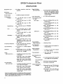
SPECIFICATIONS
Equipment Type
. . . . . . . All
silicon transistor mixer/preamplifier
Signal to Noise
(20 Hz-20 kHz)
. . . . . .Typically
83 dB at maximum output with one channel Volume
Control and MASTER Volume
Control set at 8 (approximately 58 dB gain)
Number of
lnput Channels
Power Output
..... . 8
. . . . . . . . . +19
Voltage Gain *
Program
-
dBm (program line level)
. . . . . . .87
-13 dB MIC input to LlNE
LEVEL out
37 -+3 dB LlNE input to LlNE
LEVEL out
37 -13 dB MIC input to MIC
LEVEL out
Headphones
. . . .69 -13
dB MIC input to PHONES
out
Link
. . . . .. . . . . .54.5
k 3 dB MIC input to LlNK
OUTPUT (with 600-ohm termination)
27 k 2 dB LlNK INPUT to LlNE
LEVEL output
Accessory
Distortion
LlNE lnput
. . . . . . . .33V (ATTENUATOR out;
Ch.
ume at 2)
1.35V (ATTENUATOR out;
Volume at 12)
90V (ATTENUATOR in; Ch.
ume at 2)
8.OV (ATTENUATOR in; Ch.
ume at 12)
. . . . . .59
t 3 dB MIC input to ACCESSORY output (via pins 1-8/INPUTS)
54.5 k 3 dB MIC input to ACCESSORY output (via pin
9/PROGRAM) (terminated with
600 ohms)
Frequency Response . . . k 3 dB, 20 Hz-20 kHz (150-ohm
source; 600-ohm load)
lnput Sensitivity
lnput Attenuation . . . . . . 0, 15 dB (switch-selected)
lnput Clipping Level
at 1 kHz:
MIC lnput . . . . . . . . 100 mV (ATTENUATOR out; Ch.
Volume at 2)
4.5 mV (ATTENUATOR out; Ch.
Volume at 12)
0.56V (ATTENUATOR in; Ch.
Volume at 2)
25 mV (ATTENUATOR in; Ch. Volume at 12)
. . . . . . .0.1
mV max. for +4 dBm program
output
. . . . . . . . . . . .THD
Noise
(300 Hz-20 kHz) . . . . .
less than 1% at +12 dBm,
30 Hz-20 kHz; IM distortion less
than 1% at +12 dBm
- 125 dBV (equivalent input hum
and noise at full gain)
-61.8 dBm output noise (MASTER Volume Control down)
-34.8 dBm output noise (MASTER and one channel Volume
Control up)
'Measurement conditions: MIC input through 150 ohms, LINE input through 33
kilohms LINK INPUT through 600 ohms PROGRAM LlNE LEVEL terminated in
600 oh&, PROGRAM MIC LEVEL terrhinated in 150 ohms, PHONES terminated in 8 ohms: MASTER Volume, Channel Volume and PHONES Controls
full up; all other controls and switches 0 or out.
VolVol-
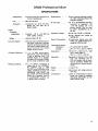
Low-Frequency
Equalization . . . . . . . . 2 1 3 dB at 100 Hz with respect to
0 (flat) setting
High-Frequency
Equalization . . . . . . . . 2 1 2 dB at 10 kHz with respect
to 0 (flat) setting
Tone Oscillator
-38.8 dBm output noise (MASTER and one channel Volume
Control up)
Ch.
. . . . . I 0 0 dB at 100 Hz
. . . . .. . . 1
- 128 dBV (equivalent input noise
at full gain)
-72.8 dBm output noise (MASTER Volume Control down)
Hum and Noise
(20 Hz-20 kHz) . . . . . .
lnput Common
Mode Rejection
Vol-
lnput Impedance at
1 kHz:
Microphone
kHz; less than 1% distortion;
variable level
. . . .2.1 kilohms balanced (for use with
25- to 600-ohm microphones)
Line (channels 7
and 8) . . . . . . . . . 66 kilohms balanced bridging
Link lnput . . . . .35 kilohms unbalanced
.
Output Impedance:
Program . .
.. . . .Balanced line level: 120 ohms ac-
tual (for use with 25- to 600ohm inputs)
Microphone level: 0.5 ohms actual (for use with 25- to 600ohm inputs)
SR109 Professional Mixer
SPECIFICATIONS
Headphones
... .3.5 ohms actual (for use with 4- to
. . . . . . . . . Output
Phase Switch
polarity-reversing switch
(0°, 180') (reverses phase of all
program outputs)
16-ohm headphones)
Link
...........600 ohms (actual)
Accessory
Limiter
Threshold
(adjustable)
Range
. . . . . . Unbalanced
aux level: 33 ohms
actual (for use with 4K or
higher loads)
..... .Typically
-20 to +20 dBm (at
LlNE LEVEL output)
............ .Approximately
Link Jack System
. . . . . . External
signal conditioning output/input; high-level auxiliary
amplifier and tape recorder signal output; multiple Mixer connection (common mix); remote
master volume control
VU Meter Calibration
Phasing (polarity)
30 dB
. . . 0,
30 Vdc Bus
..........Pin
10 on ACCESSORY OUTPUT
connector is regulated +30
k 3 . 5 Vdc supply; pin 11 is
ground (earth). May be used
to power accessories up to
50 mA.
Operating Voltage . . . . .90-132 Vac, 50/60 Hz (SR109)
90-132, 180-250 Vac, 50/60 Hz
(SR109-2E)
Power Consumption . . . 20 watts max. (Mixer only). 500
watts max. (SWITCHED AC receptacle) (SR109 only)
Temperature Range:
Operating . . . . . .-7O to 54OC (20' to 130°F)
to 160°F)
Storage ....... .-29O to 71°C (-20'
Dimensions..
f4, +8 dBm, switch-selectable (0.775, 1.23, 1.95 Vrms) at
1 kHz to 600-ohm load. [VU
RANGE Switch in 0 position
provides 0 VU reading of 0 dBm
(0.775 Vrms) to 600-ohm load1
Installation
. . . . . . . . . . . Equipped for standard 19 in. (483
mm) rack mounting; 5% in.
(133 mm) height; may be operated in accessory A105A Carrying Case or in custom control
center.
. . . . .Pin
3 of INPUT connectors in
phase with pin 9 of ACCESSORY OUTPUT, tips of LINK
OUTPUT and PROGRAM LlNE
LEVEL OUTPUTS, and pin 3 of
PROGRAM LlNE LEVEL and
MIC LEVEL OUTPUTS (PHASE
Switch in 0" position). Pins 1-8
of ACCESSORY OUTPUT out
of phase with the above.
. . . . . . . . . 133 mm H x 483 mm W X 232
mm D (See Page 4.)
(51/4 in. x 19 in. x 9% in.)
Weight
Finish
. . . . . . . . . . . . . . . 7.7 kg (17 Ib)
. . . . . . . . . . . . . . . . Matte
Certifications
black, with beige write-on
trim strip
. . . . . . . . . Listed
by Underwriters' Laboratories, Inc.; listed by Canadian
Standards Association as certified (SR109 only)
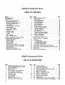
SR109 Professional Mixer
TABLE OF CONTENTS
Page
Section
ii. iii
SPECIFICATIONS
DESCRIPTION . . . . . . . . . . . . . . . . . . . . . . . . . . . . . . . . . . . 1
.............................
OPERATING INSTRUCTIONS
Functional Identification . . . . . . . . . . . . . . . . . . . . . . . . . 3
General Operating Instructions . . . . . . . . . . . . . . . . . . . 3
Mounting and Ventilation . . . . . . . . . . . . . . . . . . . . . . . . 4
Power Supply . . . . . . . . . . . . . . . . . . . . . . . . . . . . . . . . . .5
Functional Circuit Description . . . . . . . . . . . . . . . . . . . . 6
Inputchannels . . . . . . . . . . . . . . . . . . . . . . . . . . . . . . . . .6
Monitor Mixer System . . . . . . . . . . . . . . . . . . . . . . . . . . . 6
Program Mix Amplifier . . . . . . . . . . . . . . . . . . . . . . . . . . 7
Link Jacks . . . . . . . . . . . . . . . . . . . . . . . . . . . . . . . . . . . . 7
Program Output . . . . . . . . . . . . . . . . . . . . . . . . . . . . . . . 7
VU Meter Circuit . . . . . . . . . . . . . . . . . . . . . . . . . . . . . . . 7
Limiter . . . . . . . . . . . . . . . . . . . . . . . . . . . . . . . . . . . . . . . 8
Tone Oscillator . . . . . . . . . . . . . . . . . . . . . . . . . . . . . . . .8
Basic Operating
. Hints . . . . . . . . . . . . . . . . . . . . . . . . . . 8
SPECIAL OPERATING INSTRUCTIONS
High-Impedance Microphones . . . . . . . . . . . . . . . . . . . . 9
Musical Instruments . . . . . . . . . . . . . . . . . . . . . . . . . . . . 9
Tape Recording . . . . . . . . . . . . . . . . . . . . . . . . . . . . . . . . 9
Record Playback . . . . . . . . . . . . . . . . . . . . . . . . . . . . . . 10
.
.
Tape Playback . . . . . . . . . . . . . . . . . . . . . . . . . . . . . . . .11
Additional Mixer Inputs . . . . . . . . . . . . . . . . . . . . . . . . 11
.
Additional Mixer Inputs (Two SRlO9s) . . . . . . . . . . . .12
Redundant Mixer Set-up (Two SRIO9s) . . . . . . . . . . . .12
Stereo Operation . . . . . . . . . . . . . . . . . . . . . . . . . . . . . .12
.
Remote Volume Control . . . . . . . . . . . . . . . . . . . . . . . . 13
.
Telephone Line Surge Protection . . . . . . . . . . . . . . . . . 14
Section
Page
SERVICE INSTRUCTIONS
Mixer Service . . . . . . . . . . . . . . . . . . . . . . . . . . . . . . . . . . 14
Replacement Parts . . . . . . . . . . . . . . . . . . . . . . . . . . . . . 14
Fuse Replacement . . . . . . . . . . . . . . . . . . . . . . . . . . . . . 14
Knob Replacement . . . . . . . . . . . . . . . . . . . . . . . . . . . . . 14
Service Access . . . . . . . . . . . . . . . . . . . . . . . . . . . . . . . . 14
Lamp Replacement ............................. 14
Board Removal . . . . . . . . . . . . . . . . . . . . . . . . . . . . . . . . 15
Limiter Internal Adjustment . . . . . . . . . . . . . . . . . . . . . . 16
Overload Indicator Check ....................... 16
VU Meter Removal . . . . . . . . . . . . . . . . . . . . . . . . . . . . .16
VU Meter Calibration . . . . . . . . . . . . . . . . . . . . . . . . . . .16
Parts Removal . . . . . . . . . . . . . . . . . . . . . . . . . . . . . . . . . 17
Transistor and Diode Removal .................... 17
Active Component Checking ..................... 17
Service Illustrations . . . . . . . . . . . . . . . . . . . . . . . . . . . . 18
Optional Accessories . . . . . . . . . . . . . . . . . . . . . . . . . . . 18
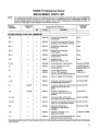
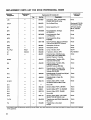
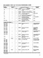
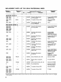
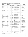
REPLACEMENT PARTS LIST . . . . . . . . . . . . . . . . . . . . . .19
NOTES TO CIRCUIT DIAGRAM
General . . . . . . . . . . . . . . . . . . . . . . . . . . . . . . . . . . . . . . .29
Troubleshooting . . . . . . . . . . . . . . . . . . . . . . . . . . . . . . .29
Ac Voltage Measurements . . . . . . . . . . . . . . . . . . . . . . .29
Dc Voltage Measurements . . . . . . . . . . . . . . . . . . . . . . . 30
Resistance Measurements . . . . . . . . . . . . . . . . . . . . . . .30
CONDENSED OPERATING INSTRUCTIONS . . . . . . . . . .35
ARCHITECTS' AND ENGINEERS' SPECIFICATIONS . .35
GUARANTEE . . . . . . . . . . . . . . . . . . . . . . . . . . . . . . . . . . . 35
.
SHIPPING INSTRUCTIONS . . . . . . . . . . . . . . . . . . . . . . . .35
SR109 Professional Mixer
LlST OF ILLUSTRATIONS
Figure
1
2
3
4
5
6
7
8
9
10
11
12
Page
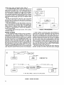
SR109 Professional Mixer Front Panel . . . . . . . . . 2
SR109 Professional Mixer Rear Panel . . . . . . . . . . 2
Overall Dimensions . . . . . . . . . . . . . . . . . . . . . . . . 5
Block Diagram . . . . . . . . . . . . . . . . . . . . . . . . . . . . .5
SR110 Monitor Mixer Applications . . . . . . . . . . . . 7
Tone Oscillator Applications . . . . . . . . . . . . . . . . 8
Preamplifier-Mixer Connections . . . . . . . . . . . . . . 9
Tape Recording . . . . . . . . . . . . . . . . . . . . . . . . . . . .10
.
Record Playback . . . . . . . . . . . . . . . . . . . . . . . . . . 10
Tape Playback . . . . . . . . . . . . . . . . . . . . . . . . . . . . .11
Additional Mixer Inputs . . . . . . . . . . . . . . . . . . . . .11
Additional Inputs: Two SRIO9s . . . . . . . . . . . . . . .12
Figure
13
14
15
16
17
18
19
20
21
22
23
24
25
Page
Redundant Mixers . . . . . . . . . . . . . . . . . . . . . . . . . .13
Stereo Tape Recording . . . . . . . . . . . . . . . . . . . . . .13
Remote Volume Control . . . . . . . . . . . . . . . . . . . . .13
Printed Circuit Board and Parts Location . . . . . . .16
Opto-Isolator Test . . . . . . . . . . . . . . . . . . . . . . . . . . 17
Board 1: Preamplifier . . . . . . . . . . . . . . . . . . . . . .24
Board 2: Channel Equalizer . . . . . . . . . . . . . . . .25
Board 3: Main Board . . . . . . . . . . . . . . . . . . . . . . 26
Board 9: Power Supply . . . . . . . . . . . . . . . . . . . . 27
Board 0: Program Mute .................... 27
Lead Codes . . . . . . . . . . . . . . . . . . . . . . . . . . . . . . . 29
SR109-2E Power Supply Circuit Diagram . . . . . .30
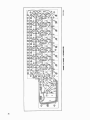
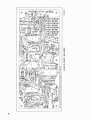
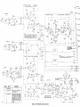
SR109 Professional Mixer Circuit Diagram . . .32-33
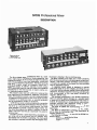
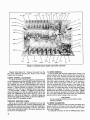
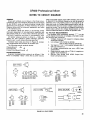
SR109 Professional Mixer
DESCRIPTION
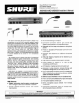
The Shure Model SR109 Professional Mixer is a solidstate, eight-channel microphone mixer-preamplifier that
enables the operator to mix as many as eight microphones
with individual control over input attenuation, volume and
high- and low-frequency equalization. The Mixer has three
outputs: a program output, an accessory output and a
headphone output. In addition, channels 7 and 8 contain
switch-selectable inputs for use with either low-impedance
microphones or line level sources. A master volume control regulates program output.
The program output has both a 600-ohm, balanced line
level output and a low-impedance, balanced, microphone
output. The headphqne output is an &ohm balanced output
with separate volume control. A pair of link jacks facilitate
connection to an additional mixer, or external equipment
such as compressors, limiters or equalizers.
The SR109 rear panel contains provisions for connection
to one or more Shure SR110 Professional Monitor Mixers.
The SR110 is a self-contained, eight-channel, line level
mixer designed to provide a separate stage monitor mix
that follows the program mix levels. In addition, it may be
used in multi-track recording as a submaster mix panel or
mixdown panel.
The SR109 contains a peak-responding, adjustable output limiter with an in-out switch and an indicator lamp
that flashes when the limiter is operating. The front panel
also contains an overload indicator lamp that signals when
the output is clipping in the non-limiting mode.
The Mixer contains a VU meter and a meter sensitivity
switch to adjust sensitivity to indicate program output level.
A built-in 1 kHz tone oscillator facilitates synchronization
of all meters in a system. A front-panel trim strip provides
space for pencilled notations.
The regulated power supply is designed to operate
over a wide range of ac line voltages, permitting the use
of extremely long ac extension cables without performance
degradation. Accessory equipment drawing up to 500 watts
may be connected to the rear-panel switched ac
receptacle (SR109 only).
The solid-state components in the SR109 Professional
Mixer are protected against damage as a possible result
of open-circuit or short-circuit conditions on the inputs or
outputs. All components are conservatively rated and are
operated well within their respective ratings to assure
long life and trouble-free performance.
The Mixer is supplied with rack-mounting screws and
spare fuses.
The Mixer is Underwriters' Laboratories, Inc., listed,
and is listed by the Canadian Standards Association as
certified (SR109 only).
The following are designed for use with the SR109 Professional Mixer:
SR110 Professional Monitor Mixer
A105A Carrying Case
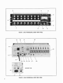
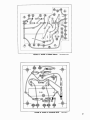
FIGURE 1. SR109 PROFESSIONAL MIXER FRONT PANEL
15
16
17
18
14
19
13
(SR109-2E Only)
27
28
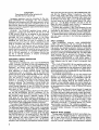
FIGURE 2. SR109 PROFESSIONAL MIXER REAR PANEL
2
SR109 Professional Mixer
FUNCTIONAL IDENTIFICATION (Refer to Figures 1 and 2,
Page 2.)
NOTE: All front panel controls are numbered for reference only.
Individual Channel Volume Controls (Eight) - Control volume and input clipping level of each channel
separately. Channel 1 contains TONE OSCillator
push-pull Switch - Pulling switch outward turns oscillator on, and rotating control adjusts level of 1
kHz tone generated internally for set-up purposes.
Individual Channel FREQuency EQualizer-LOW Rotary Controls (Eight) -Adjust low-frequency signal
equalization for each channel.
Individual Channel FREQuency EQualization-Hlgh
Rotary Controls (Eight) -Adjust high-frequency signal equalization for each channel.
LIMITER Indicator Lamp - lndicates limiting action
when LIMITER Switch (11) is turned on (IN).
OVERLOAD Indicator Lamp - lndicates Mixer overload condition (output clipping) when LIMITER
Switch (11) is turned off (OUT).
True VU Meter - lndicates volume level of program
output. (Meets all current standards for VU Meters.)
PHONES Rotary Control - Controls volume level to
PHONES Jack (8).
PHONES Output Jack- Provides for connection of
stereo or monophonic headphones for monitoring.
9. MASTER Volume Rotary control and POWER switch
-Adjusts level of totai program output, and applies
ac power to power supply and SWITCHED AC
Receptacle.
THRESHOLD ADJustment Screwdriver-Adjustable
Control -Sets threshold level of limiter function.
LIMITER IN-OUT Slide Switch -Turns program output limiter on and off.
Ac Grounded Line Cord - Connects ac power source
to Mixer power supply (SR109 only).
3AG-3/16A SLO-BLO Ac Fuse - Protects Mixer ac
input line against overload (SR109 only).
SWITCHED AC Grounded Receptacle - Provides up
to 500 watts of unfused switched ac power to accessory equipment (SR109 only).
PROGRAM OUTPUTS/PHASE Slide Switch - Reverses phase (polarity) of LINE LEVEL and MICROPHONE LEVEL program outputs with respect to
inputs.
VU METER RANGE Slide Switch - Selects VU meter
(6) sensitivity for three ranges of program level indication in dBm.
ACCESSORY OUTPUT/AUX LEVEL 11-Pin Connector - Provides output connection to Shure SR110
Monitor Mixer.
15 dB ATTENUATORS/IN-OUT Slide Switches (Eight)
- Provide choice of input signal attenuation for each
channel.
INPUTS/MICROPHONE LEVEL LOW IMPEDANCE
Three-Pin Jacks (Eight) - Provide for balanced connection of low-impedance sources to channels 1
through 8 inputs, or line level sources to channels 7
and 8.
MIC/LINE Slide Switches (Two) -Select low-impedance (MIC) or line level (LINE) input connections for
channels 7 and 8.
LlNK OUTPUT Phone Jack - Provides output connection to external equipment or common mix bus to
combine two or more Mixers.
LlNK INPUT Phone Jack - Provides input connection
from external equipment (compressor, limiter, equalizer, etc.).
PROGRAM OUTPUTS/LINE LEVEL Three-Pin Connector - Provides balanced output connection to
power amplifier.
PROGRAM OUTPUTS/LINE LEVEL Phone Jacks
(Two) - Provide balanced or unbalanced output connection to power amplifier.
PROGRAM OUTPUTS/MICROPHONE LEVEL ThreePin Connector - provides low-impedance microphone-level program output.
VOLTAGE SELECTOR Slide Switch -Selects operating voltage range of 90 to 132 or 180 to 250 Vac,
50/60 Hz (SR109-2E only).
AC (MAINS) POWER 3-Pin Connector - Connects ac
line cord to Mixer power supply (SR109-2E only).
180-250V 0.1 AT/90-132V 0.2AT SLO-BLO Ac Fuse Protects Mixer ac input line against overload
(SR109-2E only).
GENERAL OPERATING INSTRUCTIONS
WARNING
Voltages in this equipment are hazardous to life.
Make all input and output connections before ac
power is connected. Refer servicing to qualified
service personnel.
1. Using hardware provided, install Mixer securely in
standard 19 in. (483 mm) rack or optional A105A Carrying Case prior to making electrical connections.
2. Set front-panel switches to off or OUT and all controls
to 0. Set rear-panel PHASE Switch (15) to OO.
3. Connect desired PROGRAM OUTPUT/LINE LEVEL
Connector (23, 24) to power amplifier input connecting cable. (NOTE: Shure SR105 Power Amplifiers are
supplied with audio connecting cables.) If Mixer output is to be fed to another mixer or tape recorder
microphone input, use PROGRAM OUTPUT/MICROPHONE LEVEL Connector (25). If desired, connect
monophonic or stereo headphones to front-panel
PHONES Jack (8). Connect speakers to power amplifier.
4. Connect one or more low-impedance microphones to
rear-panel INPUTS/MICROPHONE LEVEL LOW IMPEDANCE Connectors (19). Any high-quality dynamic,
ribbon or condenser low-impedance microphone may
be used. Connect line level sources to channel 7 or
8 connectors only. If line level inputs are used, set
corresponding MICILINE Switch (20) to LINE.
5. If external signal-processing equipment such as an
equalizer, compressor or limiter is to be used, connect Mixer LlNK OUTPUT Connector (21) to external
equipment input and LlNK INPUT Connector (22) to
external equipment output. (See Link Jacks, Page
7, for detailed information.) If a Shure SR110
Monitor Mixer is to be used with the SR109, connect
multi-pin plug of SR110 to ACCESSORY OUTPUT
Connector (17) of SR109.
6. SR109: Connect ac line cord (12) to grounded 90- to
132-volt, 50160 Hz ac source. Line cord is a 2.4m
(8 ft), 3-conductor cord with 3-pin grounding plug.
If extension cords are required, use high-quality,
rubber-jacketed cable with 18 gauge (0.8 mm2) or
heavier wire.
SR109-2E: Obtain suitable &pin male ac connector
and attach to line cord: brown lead to "hot" or "live"
terminal, blue lead to neutral terminal, and green1
yellow lead to ground or earth terminal. (Connector
should be installed by qualified service personnel.)
Select proper operating voltage (90-132V or 180250V) using VOLTAGE SELECTOR Switch (26). Note
that switch positions are marked 115 and 220 volts.
Make certain proper fuse is installed in fuseholder
(28): O.1AT with switch set to 220, or 0.2AT with
switch set to 115. Insert female end of line cord into
chassis power connector (27) and connect male plug
to 3-wire grounded ac power receptacle providing
proper operating voltage.
7. Turn on front-panel MASTER Volume ControllPOWER Switch (9) and allow one to two minutes warmup
time. This warmup time allows the supply voltages
to stabilize and capacitors to charge to provide optimum performance. Set 15 dB ATTENUATOR Switch
(18) initially to OUT for normal PA use, to IN for
"hard" rock music. For LINE INPUT sources (channels 7 and 8), set MICILINE switch (20) to LINE.
8. Set Master Volume Control (9) to 6. Set VU METER
RANGE Switch (16) to 0 for PA or telephone line use
(when using a Western Electric 308 Voice Coupler),
+4 for recording, or +8 for broadcast use. Have
someone sing or talk into microphone and raise channel Volume Control (1) to achieve desired sound level.
If meter reads low at proper sound level, reduce
power amplifier volume level and increase channel
volume level. For single microphone set-up, if meter
indicates excessively high level ("pinning" or "pegging" needle), decrease MASTER Volume Control to
obtain good meter reading and increase power amplifier volume level or input sensitivity to obtain proper
sound level. In multiple microphone set-up, it may be
necessary to decrease MASTER Volume Control in
order to maintain channel Volume Control setting.
Ideally, set the channel Volume Controls as high as
possible (consistent with an adequate mixing range),
and increase the MASTER Volume Control to obtain
a 0 VU Meter reading. Then increase the power amplifier level control to the desired level. Using the 15 dB
ATTENUATORS (18) may aid in maintaining this setting if the channel Volume Control is consistently
set low.
9.
Set HI and LO FREQ EQ Controls (3, 2) for channel in
use. Vertical position (0) indicates "flat" frequency
response. Clockwise (+) settings increase highfrequency (treble) or low-frequency (bass) level and
counterclockwise (-) settings decrease the high- or
low-frequency level.
10.
With LIMITER Switch (11) in OUT position, OVERLOAD Indicator Lamp (5) will flash when Mixer output clipping level is exceeded. If limiting is desired,
adjust limiter as follows: Operate Mixer with program
material and adjust the channel and MASTER Volume
Controls (1, 9) for desired sound level. With small
screwdriver, turn THRESHOLD ADJ Control (10) full
counterclockwise. Set LIMITER INIOUT Switch to
IN. Slowly increase (clockwise) THRESHOLD ADJ
Control until LIMITER Lamp (4) flashes intermittently,
indicating limiting action on program peaks. A continuous glow indicates an undesirable excess of limiting: MASTER andlor channel Volume Controls
should be reduced. Increasing channel or MASTER
Volume Controls will not increase mixer output above
the level just set. Should higher or lower maximum
output level be desired, increase or decrease
THRESHOLD ADJustment. (An alternate set-up procedure uses the TONE OSCillator to produce a maximum desired VU level. The THRESHOLD ADJustment
is slowly increased (clockwise) until the VU Meter
reading just set is reduced by 1 dB. Note that with
this set-up, the program material level displayed on
the VU Meter will be lower because of the difference
between peak and average levels. However, limiting
action will take place at the same peak level. This
effect will be more evident on speech than on music.)
11.
Monitor output is available at front-panel PHONES
Jack (8). Adjust PHONES Control (7) for comfortable
listening level.
12.
NOTE: During temporary shutdown (break, intermission), do not turn off Mixer power. It is designed to
operate continuously, and optimum performance is
maintained after internal voltages are allowed to stabilize. Also, do not turn down all microphones. Leave
the master or announcer's microphone on so that if
the Mixer is left unattended, announcements may be
made, and the operator will be alerted that the next
performance is about to begin.
MOUNTING AND VENTILATION
The Shure SR109 Professional Mixer may be operated
in a standard 19 in. (483 mm) audio equipment rack (see
Figure 3, Page 5), or in a Shure A105A Carrying Case.
Four rack-mounting screws are provided with the Mixer.
The Shure A105A Carrying Case has a 7 in. (178 mm)
rack-mounting space. When the SR109 is mounted in this
case, an additional rack-mounted unit such as the SR110
Monitor Mixer may be mounted in the remaining 1% in.
(44.4 mm) space.
In rack-mounted installations, consider rear-panel access before installation is made. Although most installations will not require frequent access, it should be remembered that input and output changes, and some switch
movements, will necessitate rear-panel access.
POWER SUPPLY
SR109: The Mixer regulated power supply is designed
to operate from 90 to 132 volts ac, 50/60 Hz without adjustments, allowing the Mixer to meet all specifications
over this wide range of ac input voltages. A three-conductor, grounded line cord (12) supplies ac power to the
Mixer through the front-panel POWER Switch (9). The
Mixer consumes 20 watts maximum (0.2 amperes) and the
ac line input is protected by a 3/16-ampere slow-blow fuse
(13) and a wired-in 3/10-ampere slow-blow fuse in series.
FIGURE 3. OVERALL DIMENSIONS
'(TYPICAL OF
- 5 0 DB
ATTENUATOR
-1100
ATTENUATOR
CHXNELS
1-8)
23DB
200x~:HGH
XFMR
CHANNEL
VOLUME
CHANNEL
NOTE I
-[
m]
6 0 0 A
RESISTOR
Y
m
0
vu
0
METER
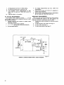
NOTES I MIC-LINE SWITCHES ON CHANNELS 7 AND 8 ONLY
2 TONE GENERATOR ON CHANNEL I ONLY
1'
PHONES
LEVEL
-
/
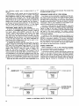
FIGURE 4. SR109 BLOCK DIAGRAM
CAUTION
These fuses should not be replaced with
any other size or type of fuse.
Accessory equipment may be connected to the rearpanel SWITCHED AC Receptacle (14). The accessory
equipment may consume up to 500 watts maximum, which
provides for use with high-power amplifiers such as the
Shure SR105. Note that the receptacle is switched but not
fused; all accessory equipment used with the Mixer should
contain its own fuse.
SR109-2E: The SR109-2E regulated power supply is
designed to operate from either 90 to 132 volts ac or 180
to 250 volts ac, 50/60 Hz, as selected by the rear-panel
VOLTAGE SELECTOR Switch (26). A three-conductor,
grounded line cord supplies ac power to the Mixer
through the front-panel POWER ON-OFF Switch (9). The
SR109-2E line cord does not have a connector on the
power source end of the cord. Obtain a suitable three-'pin
male ac connector and install it on the line cord: brown
to "hot" or "live" terminal, blue lear to neutral terminal,
and green/yellow lead to ground or earth terminal. (Connector should be installed by qualified service personnel.)
The ac line is protected by a 0.1-ampere Slo-Blo fuse (for
180- to 250-volt operation) or a 0.2-ampere Slo-Blo fuse
(for 90- to 132-volt operation. A wired-in 3/10-ampere
fuse also protects the ac line.
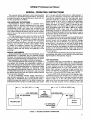
FUNCTIONAL CIRCUIT DESCRIPTION
(See Figure 4, Page 5)
Each three-pin professional audio input MICROPHONE
LEVEL Connector (19) feeds its own low-impedance balanced lnput Transformer, which provides gain of 23 dB.
Channels 7 and 8 also contain MIC/LINE Switches (20)
which switch in a 50 dB bridging line-to-microphone
level Attenuator to accept line-level inputs. The lnput
Transformers (and, on channels 7 and 8, the MIC/LINE
Switch) are fed to 15 dB ATTENUATOR Switches (18) and
then to the Preamplifier, which provides +7 to +42 dB
gain. The amount of voltage gain provided by the Preamplifier (7 to 42 dB) is controlled by the Channel Volume
Control ( I ) , providing an increase in input clipping level
as gain is reduced. The Preamplifier circuits contain the
individual Channel Volume Controls and feed the individual Channel Equalizer (HI and LO FREQ EQ) Controls
(3,2) which decrease the signal approximately 3 dB when
set to the 0, or "flat," setting.
The Equalizer outputs are fed to the Program Mix Amplifier and the ACCESSORY OUTPUT Connector (17) for
interconnection with SR110 Monitor Mixers. The Program
Mix Amplifier feeds through a 560-ohm resistor to the
LlNK jacks (21, 22). When accessory equipment is not
connected to the LlNK jacks, the jacks are bypassed and
the program signal is fed to the MASTER Volume Control
(9) and back to the ACCESSORY OUTPUT Connector.
The output of the MASTER Volume Control, after feeding
a 0 dB gain Amplifier, is sent to a Limiter Attenuator circuit.
The attenuated signal feeds a limiter, which is connected
to a Lamp Driver (for driving the LIMITER and OVERLOAD
lamps) and a Limiter THRESHOLD ADJ Control (10) for
setting the threshold of Limiter operation. Note that when
the LIMITER Switch (11) is turned off (OUT), the LIMITER
Lamp (4) will not light, but the OVERLOAD Lamp (5) will
flash whenever the output clipping level is exceeded.
The Limiter Attenuator also feeds a +7 to +35 dB output
Amplifier, also controlled by the MASTER Volume Control.
The signal then goes through a 0'-180' PHASE Switch (15),
and into the Program Output Transformer. The Transformer feeds three LlNE LEVEL Output Connectors (23,
24) and a MIC LEVEL Output Connector (25), which is at
50 dB below line level. The +7 to +35 dB output Amplifier also feeds the VU METER RANGE Switch (16), which
goes to a +22 dB Meter Amplifier and then to the VU
Meter (6), and a PHONES Level Control (7), Headphones
Transformer and PHONES Output Jack (8).
The Mixer also contains a 1 kHz Tone Generator for use
in set-up and check-out. The Generator is activated and
controlled by the channel 1 Volume Control/TONE OSC
Switch (I), and the Control output is fed to the Preamplifier.
A detailed description of the Mixer circuits and controls
and their uses is provided in the following paragraphs of
this section.
INPUT CHANNELS
Eight professional, three-pin, audio MICROPHONE
LEVEL lnput Connectors (19) are provided on the rear
panel of the Mixer. The Mixer is designed to operate with
high-quality, low-impedance dynamic, ribbon or condenser
microphones. Each low impedance microphone input is
connected to a low-impedance, balanced-input transformer
through a 15 dB input ATTENUATOR (18). Two MIC/LIINE
Slide Switches (20) are provided for channels 7 and 8.
These switches allow the user to select between either
low-impedance MICROPHONE or LlNE LEVEL inputs. If
additional line level inputs are required, Shure A15LA Line
lnput Adapters may be used in each microphone level
input.
The 15 dB ATTENUATOR (18) two-position switch provides input attenuations of 0 or 15 dB. This switch allows
the user to compensate for the differences in levels due to
different sources, such as close talking or distant microphone placement, and to compensate for high output levels
from condenser microphones.
The Channel Volume Control (1) is a dual control: one
section, in a feedback circuit, sets the gain of the preamplifier; the second section is a preamplifier output attenuator. This circuit configuration increases the preamplifier input clipping level as the Volume Control is
reduced to lower settings. Ideally, the control should operate in the middle range, between 4 and 9. This can often
be accomplished by proper 15 dB ATTENUATOR Switch
(18) setting.
The output of the Channel Volume Control (1) feeds the
equalizer circuit. Individual HI and LO FREQ EQ controls
(3,2) allow the user to shape the sound of each input channel without affecting the other channels of the Mixer. The
HI FREQ controls provide up to 13 dB of boost or cut at 10
kHz with a 1 kHz hinge point. The LO FREQ controls provide up to 13 dB of boost or cut at 100 Hz with a 1 kHz
bin-ge point. Control settings with plus (+) markings indicate boost, and minus (-) markings denote cut. A 0 setting provides a normal or "flat" frequency response.
The output of the equalizer feeds the ACCESSORY OUTPUT/AUX LEVEL Connector (17) and the Program Mix
Amplifier.
MONITOR MIXER SYSTEM
The rear-panel ACCESSORY OUTPUT/AUX LEVEL Connector (17) of the SR109 provides for interconnection to
one or more Shure SRl10 Professional Monitor Mixers.
The output of each individual channel after all channel
controls (volume, equalization and attenuation) appears
on this connector as do the LlNK INPUT total mix signal
and the power supply connections. The SR110 is a selfcontained, eight-channel, line level mixer designed for
use with the SR109 or similar equipment. The SR110 can
provide a separate stage monitor "mix" that follows the
program "mix" levels coming from the eight channels of
the SR109. In addition, it may be used in multi-track recording as a submaster mix panel or as a "mixdown"
panel.
The SR110 provides eight high-impedance, unbalanced,
line level inputs to its mixing circuity, one high-impedance,
unbalanced, line level input to its Output Selector Switch
for monitoring the program mix, and one line level, 600ohm, balanced output. Individual channel and master volume controls are provided, as is a switch to choose between monitoring the channels in use (Mixed Inputs) and
the total program mix (Program Input). The Mixed Inputs
position takes the signal from each channel frequency
equalization circuit, and the Program Input position obtains
the mixed signal at the LlNK INPUT Jack (22).
The SR110 has parallel accessory input/output male and
female connectors. These connectors permit the connection of addition tandem or "stacked" SRllOs. A typical
application is shown in Figure 5, Page 7.
PROGRAM MIX AMPLIFIER
The program mix amplifier is an active mixing amplifier in which gain remains constant independent of the individual channel volume control settings. The output of
the program mix amplifier is connected through a 560-ohm
mixing resistor to the LlNK Jacks (21, 22).
SR1w
MIXER
LINE
LEVEL
POWER
AMPLIFIER
PA
SPEAKERS
POWER
AMPLIFIER
STAGE
MONITOR
SPEAKER
OUT
ACC
SRl I 0
MONITOR
MIXER
SRllO
MONITOR
MlXER
STEREO
TAPE
RECORDER
SRllO
MONITOR
MIXER
FIGURE 5. SRllO MONITOR MlXER APPLICATIONS
LlNK JACKS
The LlNK Jacks (21,22) on the rear panel of the Mixer
enable the user to interconnect more Mixers for additional
inputs or add external equipment, such as equalizers,
compressors, or limiters. When connecting two or more
SR109 Professional Mixers together to provide many channel inputs, connect the LlNK OUTPUT Jacks (21) of all
the units together. It should be noted that the LlNK OUTPUT Jack is actually a two-way jack; the impedance at
this point is actually 600 ohms, and any number of units
may be tied together at this point. The LlNK INPUT Jack
(22) is an input-only jack and has switching contacts that
disconnect the LlNK OUTPUT signal from the MASTER Volume Control (9). Note that the SR109 and the Shure SR101
Audio Console may be interconnected in the same manner.
If an equalizer, limiter or compressor is connected to
the Mixer, the LlNK OUTPUT Jack (21) is connected to
the input of the external unit and the output of the external
unit is connected to the LlNK INPUT Jack (22).
The signals at the LlNK Jacks are typically at a level
10 dB below line level. These jacks will accommodate signal levels in the range between 3 0 to +10 dBm. The
LlNK INPUT impedance is greater than 20 kilohms and
may be considered a bridging impedance. The output of
the LlNK Jacks feeds the MASTER Volume Control (9)
which is a two-section control similar to those used in the
individual channels. The LlNK INPUT Jack is connected
to the ACCESSORY OUTPUT/AUX LEVEL Connector (17).
PROGRAM OUTPUT
The signal from the LlNK Jacks (22, 21) drives the program output amplifier. The gain of this amplifier is controlled by one-half of the MASTER Volume Control (9) (the
other half is an input attenuator for the output amplifier).
In addition to the limiter circuitry, the program output
amplifier also contains the front-panel OVERLOAD Indicator Lamp (5). This indicator will flash when the output
clipping level is exceeded, and only when the LIMITER
Switch (11) is in the OUT position. The output of the program amplifier is sent to the PHASE Switch (15) mounted
on the rear panel of the Mixer. This switch allows the user
to change the phase of the program output, which may be
helpful in eliminating or reducing low-frequency acoustic
feedback. Generally, this switch is adjusted to the position
which either gives the most gain before feedback or, if both
positions give the same gain before feedback, use the position that produces the highest pitch feedback. The program signal, after leaving the PHASE Switch, is routed
to the output transformer which provides both LlNE LEVEL
and MICROPHONE LEVEL outputs. The LlNE LEVEL output is connected to one professional three-pin, male, audio
output connector (23) and two three-circuit phone jacks
(24). The MICROPHONE LEVEL output is a low-impedance,
balanced output, 50 dB below the LlNE LEVEL output, and
is connected to a professional three-pin, male, audio output connector (25).
Note that all of the program outputs are balanced with
respect to ground. If a two-circuit type phone plug is used
to connect the mixer line level output to an amplifier or
tape recorder, the line outputs will automatically become
unbalanced. If the three-pin unbalanced output is used and
a phone jack output is also to be used, obtain a stereo
phone plug and corrnect the tip and ring of the plug only.
(The sleeve is a shield and would cause a ground loop.)
If it becomes necessary to use the MICROPHONE LEVEL
Output Connector (25) to feed a high-impedance microphone input, use a line matching transformer such as one
of the Shure A95 Series at the high-impedance microphone
input.
The output of the program output amplifier is also fed
to the VU Meter (6) circuit.
VU METER CIRCUIT
To allow a wide range of signals to be handled by the
VU Meter (6), a VU Meter amplifier is provided. The output
of the program amplifier is fed to the VU METER RANGE
Switch (16) which in turn feeds the VU Meter amplifier and
the Meter. The VU METER RANGE Switch provides a
choice of 0, +4 or +8 dBm output levels for the VU Meter.
The 0 setting is usually used for PA applications, +4 is the
standard for recording use, and +8 is preferred for use
by broadcasters. The calibration of the VU METER RANGE
Switch is internally adjusted at the factory for 0 VU across
a 600-ohm load on the program output in the +4 dBm
switch position. The VU Meter amplifier provides the
proper impedance and signal level for correct VU Meter
ballistics and calibration. This amplifier also isolates the
Meter from the program output and eliminates the distortion normally caused by the nonlinearities of VU meters.
LIMITER
The program output amplifier also contains a peakresponding, rapid-acting, limiter circuit. When the LIMITER Switch (11) is turned on (IN), and the THRESHOLD
ADJ Control (10) is properly adjusted, the LIMITER Indicator Lamp (4) will flash whenever the limit threshold is
exceeded and the limiter is functioning. The dynamic range
of the limiter is approximately 30 dB.
Set the limiter THRESHOLD ADJ Control (10) as follows. Operate the Mixer with program material, and adjust
the individual channel and MASTER Volume Controls
(1, 9) for the desired level. With a small screwdriver, turn
the THRESHOLD ADJ Control full counterclockwise. Set
the LIMITER IN-OUT Switch (11) to IN. Slowly increase
(turn clockwise) the THRESHOLD ADJ Control until the
LIMITER Indicator Lamp (4) flashes, indicating limiting action on program peaks. Note that increasing the channel
or MASTER Volume Controls will not increase the mixed
output above the level just set. Should a higher or lower
maximum output level be desired, increase or decrease
the THRESHOLD ADJ Control.
An alternate method of limiter threshold adjustment is
to turn on the TONE Oscillator (1) to produce a maximum
reference level on the VU Meter (6). Adjust the THRESHOLD ADJ Control (10) clockwise until the VU Meter reading
just set is reduced by 1 dB. The program material displayed on the VU Meter will be lower because of the
difference between peak and average levels, but limiting
action will take place at the same peak level. This effect
will be more evident on speech than music.
TONE OSCILLATOR
The Mixer contains a built-in 1 kHz tone oscillator for
set-up and check-out purposes. The TONE OSC Control
and On-Off Switch (1) injects the 1 kHz tone into the channel 1 preamplifier. The tone is processed through the program channel in the same manner as microphone or line
input signals.
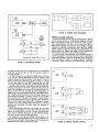
The tone oscillator may be used as follows: With the
VU METER RANGE Switch (16) set to +4, increase the
MASTER Volume Control (9) and TONE OSC Control (1)
until a 0 VU reading is obtained on the VU Meter. A tone
reference level has now been established. The Mixer LlNE
LEVEL Output (23, 24) is now 4-4 dBm (1.23 volts across a
600-ohm load) and the MICROPHONE LEVEL Output (25)
is approximately 4 millivolts. These reference signals may
be used to set up power amplifiers, tape recorders, or other
equipment connected to these outputs (Figure 6A, Page
8). By adjusting the input level (or volume) controls on
the associated equipment, all meters in the audio system
can be made to "track." This allows the Mixer operator to
observe only the Mixer VU Meter.
The tone oscillator may also be used to provide a check
of cables and equipment connected to the link output.
With the LlNK OUTPUT Jack (21) connected to the input
@
MIC
LINE
SR 109
MIXER
@
LINE
POWER
AMPLIFIER
MIC
TAPE
RECORDER
-
POWER AMPL
AUX LEVEL
INPUT JACK
SR 109
MIXER
GATED
COMPRESSOR
MIXER
FIGURE 6. TONE OSCILLATOR APPLICATIONS
of external equipment, such as a Shure SE30 Gated Compressor/Mixer which in turn feeds a broadcast line, disconnect the Mixer output, either at the back of the Mixer,
power amplifier or speakers (Figure 6B, Page 8). Set
the MASTER Volume Control (9) to 6 or the normal operating position, and increase the TONE OSC Control (1)
for a 0 VU reading on the VU Meter (6). Set the MASTER
Volume Control to 0. Under this set-up condition, the external equipment may now be calibrated or checked out
without affecting the Mixer output. After calibrating the external equipment, turn off the tone oscillator, and return
the MASTER to the previous setting. Reconnect the power
amplifier or speakers.
BASIC OPERATING HINTS
Should any difficulty be encountered in Mixer operation,
the problem may often be traced to some simple source
such as an error in interconnection. The following is offered as a basic guide to problems of this sort.
Symptom:
Check:
Symptom:
Check:
Symptom:
Check:
Mixer is "dead" (no output, VU METER lamps
out)
1. Check that ac power source is "live" and
that Mixer is plugged in.
2. Check that POWER OFF Switch (9) is on.
3. Check to see that rear-panel SLO-BLO
Fuse (13, 28) is good.
Mixer is "dead" (no output, VU Meter lamps
lit)
1. Check that cable from PROGRAM OUT
PUT/LINE LEVEL Connector (23) has not
accidentally been connected to PROGRAM OUTPUT/MICROPHONE LEVEL
Connector (25).
2. Check that PHASE Switch (15) is not between positions.
3. If external equipment is connected to
LlNK Jacks (21, 22), disconnect external
equipment to determine whether fault is
in external equipment.
One channel is "dead" (other channels operating properly)
1. Check for defective input cable or source.
2. Check that MIC/LINE Switch (20) (channels 7 and 8 only) is not between positions
or in the wrong position.
SR109 Professional Mixer
SPECIAL OPERATING INSTRUCTIONS
The previous section described normal interconnection
and operation of the SR109 Professional Mixer; this section
provides information on special set-ups to more fully utilize the capabilities of the Mixer.
HIGH-IMPEDANCE MICROPHONES
High-impedance dynamic, ribbon or condenser microphones (crystal Or ceramic
are
recornmended) can be used with One
the 1°w-im~edance
MICROPHONE LEVEL Input Jacks (191, providing a line
matching transformer (Shure A95 Series) is used. NOTE:
The l5
dB ATTENUAToR Switch may be used
'Ompenthe very high Output produced
sate
microphones.
The high-impedance cable should be limited to 6m (20
ft). If a long cable length is required, use up to 3m
ft)
of high-impedance, single-conductor, shielded cable (Belden #8401, #8410, or #8411) between the microphone
and line matching transformer, and add as much low-impedance, two-conductor, shielded cable (Belden #8412
or #8422) as necessary between the transformer and
Mixer input jack. These precautions will help avoid highfrequency signal loss and reduce the possibility of hum
and noise.
MUSICAL INSTRUMENTS
Musical instr~ments,aco~stical(n0n-electrified), acoustical-electrical, or electrified, may be amplified through
the Mixer. For acoustical instruments, place a microphone
close to the instrument strings, sounding board, or mouth.
Adjust equalization and volume controls as necessary.
For acoustical-electrified instruments such as classic or
folk guitars with pickups and preamplifier outputs, or
pianos with pickups and preamplifier outputs, either place
the microphone as described above, or connect the pickup
to a line matching transformer as described under
High-Impedance Microphones (Page 9). Adjust the 15 dB
ATTENUATOR Switch (8) for the channel in use to provide
the desired sound level with the channel Volume Control
(1) set at about mid-scale.
To use a preamplifier auxiliary output (instrument or
tape recorder preamplifier, or hi-fi amplifier tape monitor
output jack, or headphone jack; not the speaker jacksamplifier damage may result) with the Mixer, connect the
preamplifier auxiliary output to a LlNE LEVEL input (chan-
r
nel 7 or 8 jack with MIC/LINE Switch in LlNE position). If
the source is unbalanced, connect the cable shield to pin
1 and the hot conductor to pin 3 of the input jack. As an
alternate connection, connect the preamplifier auxiliary
output through up to 3m (10 ft) of cable to the high-impedance side of a line matching transformer (Shure A95
series) as shown in ~i~~~~
7, Page 9. connect the lowimpedance side of the transformer through a low-impedante microphone cable (up to 300m-1000
ft) to a Mixer
MICROPHONE LEVEL Input Jack (19). Adjust Mixer
equalization controls for optimum sound. ~ d jthe~ Mixer
~ t
15 dB ATTENUATOR Switch (18) for the channel in use to
provide the desired sound level with the channel Volume
Control (1) set at about mid-scale.
Fully electrified instruments may also be amplified using
a
in front of the instrument speaker, Or the inOutput
the speaker jack;
damage
may
may be fed
to an
jack as described above. It is important to note that the tonal quality
of fully electrified instruments is primarily formed by the
instrument amplifier and speaker; an external microphone
Output may very
picking up the instrument
provide a more desirable sound than that obtained by direct connections.
The cable length restrictions applying to high-impedance
microphones also apply to most musical instruments (see
High-Impedance Microphones, Page 9).
TAPE RECORDING
The Mixer output may be recorded on a tape recorder
from either the LINE LEVEL Output (23,241, MICROPHONE
LEVEL Output (25) or LINK OUTPUT (21) Jacks. The Mixer
Program Outputs are after the MASTER Volume Control
(9) and LIMITER Switch (11); the LINK OUTPUT Jack is
before these features. In planning a tape recorder connection, the operator should decide whether he wants the
tape level to follow the MASTER Control and LIMITER.
To use a LINE LEVEL Output Jack (23,24) feeding a highimpedance auxiliary tape recorder input, connect a cable
from one LlNE LEVEL Jack to the tape recorder input (see
Figure 8, Page 10). If the LlNE LEVEL Output is being
used and a two-circuit phone jack is used to connect the
Mixer to the tape recorder, this will unbalance the LlNE
p=-UP
3 m (10') MAX.-
TO 3 0 0 m (1000')
>
HIGH IMPEDANCE
AUX OR HEADPHONE
OUT
A95
LINE
MATCHING
TRANSFORMER
LOW IMPEDANCE
PREAMPLIFIER
LOW IMPEDANCE
MICROPHONE
CABLE
1
1
MIC LEVEL
INPUT
SR 109
MIXER
FIGURE 7. PREAMPLIFIER-MIXER CONNECTIONS
9
LEVEL Output (refer to Program Output, Page 7).
If the MICROPHONE LEVEL Output Jack (25) is to be
used, connect a cable from it to the tape recorder lowimpedance microphone input. If the microphone input on
the tape recorder is designed to be used with high-impedance microphones (greater than 1000 ohms), insert a
line matching transformer (Shure A95 Series with proper
connectors) between the MICROPHONE LEVEL Output
Jack and the tape recorder input (refer to Program Output,
Page 7).
To use the LlNK OUTPUT Jack (21), use a two-circuit
phone plug on the cable to the tape recorder auxiliary or
line input. The input impedance of the tape recorder should
be 600 ohms minimum.
The output impedance of the LlNK OUTPUT Jack (21) is
low; this provides for unlimited cable length between the
Mixer output and tape recorder input. Low-capacitance,
single-conductor, shielded cable (Belden #8401, #8410,
or #8411) is recommended to reduce the possibility of
hum and noise pickup.
For operation with a stereo tape recorder, refer to Stereo
Operation, Page 12.
RECORD PLAYBACK
To play records through the Mixer using a turntable or
record changer with a stereo magnetic cartridge and no
preamplifier, the most expedient method is to join the left
and right channel leads from the turntable in a "Y" adapter
and connect the joined output through an A95 Series Line
Matching Transformer to a MICROPHONE LEVEL lnput
Connector (19) on the Mixer (see Figure 9A, Page 10).
Note that the total lead length between the turntable and
the A95 should not exceed 1.5m (5 ft). To approximate the
RlAA equalization curve, set the Mixer FREQ EQ-LO Control (2) to +4, the FREQ EQ-HI Control (3) to -6, and the
15 dB ATTENUATOR Switch (18) to 0 for the channel being
used. Adjust the channel Volume Control (1) as necessary.
@
I
LOW IMPEDANCE
BALANCED LINE
1
I
I
MIC LEVEL OUTPUT
I
I
1
FIGURE 8. TAPE RECORDING
A better method of performing this interconnection involves the use of a phono preamplifier such as the Shure
M64 Stereo Preamplifier (see Figure 96, Page 10). In
this set-up, RlAA equalization will be achieved at the preamplifier, before the signal enters the Mixer. In this manner,
the Mixer equalization controls may be used to optimize
the room sound, rather than compensating for the input
signal. The joined turntable leads enter the channel 1 input
of the preamplifier, and the output is taken from the channel 1 low level output and fed to a MICROPHONE LEVEL
lnput Jack (19) of the Mixer. Set the Mixer 15 dB ATTENUATOR Switch (18) to 0 with this set-up.
Note also that this set-up removes the cable restriction
between turntable and Mixer described above; although
A95
M I C INPUT
SR 109
MIXER
TURNTABLE
1.5 m
@
(5')
MA
=
X
-.
(
FREQ. EQ-L0:+4
FREQ. EP-HI: -6
p-UP
'
CHAN.1
r
INPUT
M 6 4 STEREO
PREAMPLIFIER i
TO 300 rn
CHAN. I
LOW LEVEL
OUTPUT
)
(1000')
1
MIC INPUT
SRlOS
MIXER
TURNTABLE
4f
ONLY
ONE CHANNEL IS USED FOR THIS APPLICATION.
FIGURE 9. RECORD PLAYBACK
a maximum of 1.5m (5 ft) between turntable and preamplifier is mandatory, the cable length between the preamplifier and Mixer is virtually unlimited.
TAPE PLAYBACK
To play tape-recorded material through the Mixer, connect a cable from the tape recorder auxiliary or line level
output to the channel 7 or 8 LlNE LEVEL lnput Jack (19).
For unbalanced tape recorder outputs, connect a singleconductor, shielded cable as shown in Figure 10, Page 11.
Connect the tape recorder output cable shield to pin 1
and the "hot" conductor to pin 3 of the SR109 LlNE LEVEL
lnput Jack.
Set the rear-panel MIC/LINE Switch (20) on channel 7
or 8 (whichever is being used) to LINE. Set the 15 dB ATTENUATOR Switch (18) to 0, and the channel Volume
Control (1) as required.
TAPE RECORDER
AUX OUTPUT
SR109 MlXER
c-------
\ I
------- --
(CHANNEL 7 OR 8)
ure 11B, Page 11). Set the SR109 15 dB ATTENUATOR
Switch (18) to 0 and the MIC/LINE switch to LINE. To use
this set-up with other mixers, essentially the same procedure is followed. The Shure M67 mixer, for instance, may
be connected to the SR109 LlNE INPUT Jack through the
mixer line out connector (binding posts) or headphone output (phone jack) (Figure 11C, Page 11).
If a mixer is to be used with the SR109 but it is desirable
to maintain as many SR109 channels as possible, the mixer
can be connected to the LlNK OUTPUT Jack (21) (Figure
I l D , Page 11). However, this requires sacrificing the
channel equalization functions for the sources entering
through the mixer. The only SR109 control functions operating on the mixer sources in this set-up are the MASTER
Volume Control (9), LIMITER Switch (11) and rear-panel
PHASE Switch (15). In addition, any mixer used in this setup requires a 2.2-kilohm resistor in series with the mixer
output to provide an attenuator bridging connection; the
resulting signal level will be down -10 dB (see Figure 11E,
Page 11). The M67 Mixer headphone jack has suitable
built-in resistors and may be connected directly to the
SR109 LlNK OUTPUT Jack. Only mixers with 600-ohm line
outputs may be used in the configuration. Note that the
Shure M68FC mixer cannot be used this way.
The mixer-to-link out jack connection can also be used
with several mjxers. Each mixer output must contain its
FIGURE 10. TAPE PLAYBACK
LOW IMPEDANCE
MIC LEVEL
ADDITIONAL MlXER INPUTS
Additional microphone or other source inputs may be
obtained using a high gain, low noise, microphone mixer
such as the Shure M68FC. When connected to a MICROPHONE LEVEL lnput Jack (19), the M68FC and SR109 will
provide a total of 11 inputs (see Figure 11A, Page 11).
(Note that adding a mixer at an lnput Jack converts that
channel to a submaster control; the total number of inputs
will thus be the mixer total plus the SR109 total ---8 minus 1 for the submaster.)
A common practice when adding a mixer in this manner
is to connect similar-use microphones (for instance, all
drum, string or horn microphones) to a single mixer which
is fed into the SR109. The SR109 individual channel Volume Control (1) then controls an entire section, facilitating
adjustment of that section during a performance. With this
set-up, set the channel 15 dB ATTENUATOR Switch (18)
to 0 and adjust the mixer channel volume controls in the
mid-to-high range. Adjust the mixer master volume control
as required to keep the SR109 channel volume control in
the desirable middle range.
The M68FC mixer has a switch-selectable low- or highimpedance microphone output. When using an M68FCtype mixer into an SR109 MICROPHONE LEVEL lnput Jack
(19), set the mixer MIC OUT switch to low impedance, and
make necessary adjustments as described above. It is
sometimes desirable to use the auxiliary output from the
mixer into the SRl09 channel 7 (or 8) LlNE INPUT (19).
(Refer to Tape Playback, Page 11, for a description of
this set-up.)
To use this set-up with an M68FC mixer, connect a cable
between the mixer auxiliary output (phono pin jack) and
the SR109 LINE INPUT Jack (19) on channel 7 (or 8) (Fig-
M68FC
MIXER
AUX LEVEL
@
MIXER
LlNE OUT OR
PHONES OUT
0
0
,,
MIXER
MIC
LEVEL
SR109
MIXER
L l N E LEVEL
SR109
MIXER
SRlOS
MIXER
SRlOS
MIXER
600Ll
LlNE OUT
MIXER
TOTALaII CWNNELS
LlNE LEVEL
PHONES
MIXER
vT" 6M
TOTAL.11 CHAP:NELS
SRIO,
MlXE R
;$
,
,
TOTAL: I I CHANNELS
TOTAL I 2 CHANNELS
(NO EWALlZATlON
ON M67 INPUTS)
TOTAC. I 2 CHANNELS
(NO EOUAUZATI ON
ON MlXER INPUTS1
FIGURE 11. ADDITIONAL MIXER INPUTS
D
LlNK
OUT
SRllO
SR109
MONITOR
MlXER
D
SR1Os
MIXER
RESISTIVE
NETWORK
LINE
LEVEL
I
L
STEREO
MlXER
TAPE
ACC OUT
AUX L E V E L
POWER
AMPLIFIER
RECORDER
SRllO
1
I
I
I
MONITOR
MlXER
R
-
-
I
I
LINK
OUT
I
SR1Os
MIXER
FIGURE 14. STEREO TAPE RECORDING
I
LlNE
LEVEL
I
I
I
I
LlNE LEVEL
I
L
POWER
AMPL
BALANCED
BRIDGING
INPUT
- - - - - - - -J
RESISTORS ARE CARBON COMP., 1/2 W.5%
REMOTE VOLUME CONTROL
A remote volume control may be constructed for adjusting the output level at a considerable distance from the
Mixer. For remote control up to 15m (50 ft), obtain a lineartaper potentiometer with knob (any value from 1000 to
2500 ohms), a standard phone plug, and a length of singleconductor, shielded microphone cable (such as Belden
#8401, #8410, or #8411). Connect the potentiometer and
plug as shown in Figure 15A, Page 13, and connect the
phone plug to the Mixer LlNK OUTPUT Jack (21).
If hum or noise is encountered with the above set-up, i t
may be necessary to provide a two-wire control. Using the
same potentiometer, obtain two standard phone plugs and
twice the desired length of single-conductor, shielded
microphone cable. Connect the potentiometer and plugs
FIGURE 13. REDUNDANT MIXERS
ing tape channel input; an omnidirectional unit suspended
from the ceiling will pick up the full acoustic output of
the instruments.
An ideal method of recording the SR109 output in stereo
is to use two SR110 Professional Monitor Mixers. This
method allows the SR109 output to be used for the PA
system. Connect the SRllOs as shown in Figure 14, Page
13, with the output of one SR110 feeding the left input
of the tape recorder and the other SR110 feeding the right.
Note that the controls of the SRllOs permit spatial positioning ("panning" from left to right) and also allow different level settings to be used on the recording as opposed to the PA level. Spatial channel assignment or
positioning is accomplished as follows: If the SR109 channel 1 input is to be recorded on the left tape channel, set
the left SR110 channel 1 volume control for the proper
level and leave the right SR110 channel 1 volume control
at 0. If the second tape input is to be recorded "centered"
(both left and right), adjust both SR110 channel 2 volume
controls to the same setting. Note that these two controls
combine the functions of record level and panning or
positioning.
SR109 instrumental channels that are set at a low level
for PA use with respect to vocal channels should be set
higher on the SRllOs to provide a proper recording balance. Once the SR110 levels are set, the SR109 provides
the "mix" for both PA and tape recording.
An expansion of the above method may be used to record 4-channel (quadriphonic) sound. In this-method, four
SRllOs are connected to the four tape recorder inputs, and
adjustments are made as described above.
@
--
LlNK
SRlOS
OUT
I
--
--
@
SRlOS
MIXER
---
0
r - - - - - - - 7
I
SRIOS
MIXER
I
LlNK
IN
,\
I
I
I
WHITE
BLACK
I
"
L- - - - - - - - -
FIGURE 15. REMOTE VOLUME CONTROL
I
J
as shown in Figure 158, Page 13, and plug the control
assembly into the LlNK OUTPUT (21) and LlNK INPUT
(22) Jacks.
For distances over 15m (50 ft) or for permanent installations where hum or noise may be encountered, use
low-capacitance, two-conductor, shielded cable (Belden #8412 or #8422). Connect as shown in Figure 15C,
Page 13, and use a metal box to contain the potentiometer. The cable shield must be connected to the metal
box containing the potentiometer, to the common conductor (black), and not to the sleeve connections of the
phone plugs. IMPORTANT: To avoid hum caused by a
ground loop, do not ground the metal box to any metal
such as electrical conduit, water pipes, heating ducts, or
structural steel.
TELEPHONE LINE SURGE PROTECTION
When using the Mixer to feed a telephone line that may
be subject to lightning-induced voltage surges, the following part should be installed across the telephone line to
provide additional protection for output circuit components: Thyrector, General Electric Part No. 6RS20SPlBl.
SR109 Professional Mixer
SERVICE INSTRUCTIONS
MIXER SERVICE (SEE GUARANTEE, Page 35.)
The SR109 Professional Mixer uses components of the
highest quality, operating well within their respective ratings to assure long life.
WARNING
Voltages in this equipment are hazardous to life.
Make all input and output connections before ac
power is connected. Refer servicing to qualified
service personnel.
REPLACEMENT PARTS
Parts that are readily available through local electronics
parts distributors are not shown on the accompanying
Parts List. Their values are shown on the Circuit Diagram
(Figure 25, Pages 32-33). Commercial parts not readily
available and unique parts are shown on the Parts List
and may be ordered directly from the factory.
The commercial alternates shown on the Parts List
are not necessarily equivalents, but may be used in the
event that direct factory replacements are not immediately
available. To maintain the highest possible performance
and reliability, Shure factory replacement parts should be
used. When ordering replacement parts, specify the Shure
Replacement Kit Number (RKC), description, product
model number, and serial number.
FUSE REPLACEMENT
To replace line fuse F1 (with no apparent problems in
the Mixer), disconnect the line cord from the ac source
and remove the rear-panel fuseholder cap. Replace the
defective fuse only with a 3AG-3/16A Slo-Blo fuse
(SR109 only; SR109-2E contains a 0.1A Slo-Blo fuse for
180- to 250-volt operation, or a 0.2A Slo-Blo fuse for 90to 132-volt operation).
CAUTION
If trouble symptoms -overheating,
erratic operation, etc. -were
apparent before the fuse
blew, or if the replacement fuse blows, a qualified serviceman should troubleshoot the Mixer
carefully to find the source of the trouble. Do
not continue to replace fuses until the trouble has
been corrected.
The Mixer also contains a wired-in fuse in series with
rear-panel line fuse F1 (F2, 3/10A, Slo-Blo). If replacement
becomes necessary, replace only with an identical fuse.
KNOB REPLACEMENT
All front-panel control knobs are pull-off types and are
interchangeable with others of the same function. When
ordering replacement knobs, be sure to order the proper
color-coded type for the desired control.
SERVICE ACCESS
To open the Mixer for servicing, remove the eight Phillips head screws securing the top cover and remove the
top cover. Rear-panel-mounted parts and the preamplifier
assembly may be reached by removing the eight Phillips
head screws securing the rear panel, and carefully moving
the rear panel assembly out and downward. Front-panelmounted parts may be reached by removing the two screws
at the top of the cover channels and the four screws at the
bottom of the chassis, and carefully moving the front panel
assembly out and downward.
LAMP REPLACEMENT
To replace either of the two #47 lamps (PLl,PL2) illuminating the VU Meter (MI), carefully raise the metal
c l i assemblv
~
holdina the lam^ to be r e ~ l a c e duoward and
of; the power suppry printed circuit board biacket. Lift
the lamp socket upward, taking care not to crimp or break
any associated wiring. Replace the defective lamp and
carefully return the lamp assembly to its original position.
To replace either of the two light-emitting diodes (LED'S)
(DI,D2) mounted on the front panel, remove the outer
insulating tubing and mounting ring from the rear of the
LED. Press against the front-panel portion of the LED envelope to force it out the back through the mounting clip.
Unsolder both LED gray leads from the Power Supply assembly. Remove the Power Supply assembly and VU Meter
(see VU Meter Removal, Page 16). Unsolder the LED
orange lead from the LIMITER OUT-IN Switch (S12) or
THRESHOLD ADJ Control (R10) (depending on which is to
be replaced). Insert the replacement LED in the front
panel and place the mounting ring and insulating tubing
over the leads. Solder the orange lead in place, loosely
coiling the two LED orange leads together. Replace the
VU Meter and Power Supply assembly. Loosely coil the
two LED gray leads together and re-solder them to the
Power Supply ground terminal.
The above is the recommended procedure for LED replacement. In an emergency, the LED wires may be spliced
and insulated (with tape or tubing) without removing the
VU Meter or Power Supply.
BOARD REMOVAL
The various printed circuit boards are mounted in different manners. The following paragraphs describe the
best method of removing these boards after wires and
cable assemblies have been removed. IMPORTANT: When
disconnecting push-on terminals or soldered board connections, make sure each wire is identified for proper
reconnection. This may be done by affixing a piece of
masking tape marked with the connection or terminal
letter to each wire.
Wire colors are given in the following table.
CAUTION
Similar wire colors are used in different circuits;
make sure proper re-connections can be made.
Take care not to bend or break the push-on terminals. Remove or replace terminals by grasping
the terminal itself; do not pull on the associated
wire.
Preamplifier Board
Letter
Wire Color
Letter
Brown
G/Ch. 6
Orange
Yellow
Green
G/Ch. 8
Wire Color
White
Black
Equalizer Boards
A
B
C,D/Ch. 1
C,D/Ch. 2
C,D/Ch. 3
Red
Black
Brown
White/Red
Orange
A
B
C
D
E
F
G
H
J
White
Gray
Blue
Green
Yellow
Orange
White/Red
Brown
Black
C,D/Ch.
C,D/Ch.
C,D/Ch.
C,D/Ch.
C,D/Ch.
4
5
6
7
8
Yellow
Green
Blue
Gray
White
Main Board
K
L
M
N
Q
R
S
T
V
Blue
White/Purple
Gray
White/Green
Yellow/Red
Yellow
Purple
Orange
Green
"1 ;1: 1
Main Board (Cont'd.)
Black
White
Red
White/Green
Black
White
AA
AB
AF
AG
AH
White/Red
Green
Brown
Black
Red
Black
Power Supply Board
Red (5)
Yellow
Black
Gray
Green
Yellow
Black (7)
F
G
Program Mute Board
NOTE:
I
Green/White
Red
ID
E
White
Green
Production variations may result in wire colors
differing from those in the table.
Refer to Figure 16, Page 16, for the location of each board.
The function of each board assembly is defined in the table
below.
Board No.
Component Numbering
Preamplifier Board
Equalizer Boards (8)
Main Board
Power Supply Board
Program Mute Board
100's
200's
300's
900's
90's
When removing front-panel control retaining nuts with a
Y2" nutdriver or wrench, be careful not to damage the
black plastic surface.
Remove boards from nylon fasteners by squeezing the
upper protruding tab on the circuit board side inward and
sliding the board outward and off the fastener. The fasteners may be removed from the support bracket by squeezing both tabs securing the fastener to the bracket and
pushing the fastener through the bracket hole. NOTE:
When replacing nylon fasteners, be sure the protruding
tab on the circuit board side is oriented towards the top
of the chassis. Failure to do so will make future board
removal difficult.
Preamplifier (Board 1): Remove the board from the
seven nylon fasteners (see procedure above) securing the
board to the vertical bracket, disconnect the eight colorcoded channel output leads, and lift the board up for
service access.
Channel Equalizer (Board 2):
Each of these eight
boards may be removed by removing the two front-panel
equalizer control knobs and retaining nuts associated with
that channel. The Channel Equalizer Boards are identical
and may be interchanged without modification.
Main Board (Board 3): Remove the board from the six
nylon fasteners (see procedure above) securing the board
to the vertical bracket, remove the 41 push-on leads, and
lift the board upward.
Power Supply (Board 9): Remove the four screws securing the board and lift straight up.
FIGURE 16. PRINTED CIRCUIT BOARD AND PARTS LOCATION
Program Mute (Board 0): Remove the board from the
four nylon fasteners securing the board to the vertical
bracket and lift upward.
LIMITER INTERNAL ADJUSTMENT
To adjust the limiter function following replacement of
circuit components, set the MASTER Volume Control (R9)
to full clockwise. With the LIMITER Switch (S12) in the
OUT position, turn on the TONE OSCillator (Rl) (with all
other microphone inputs full counterclockwise) and adjust
channel 1 Volume Control to produce a VU Meter (MI)
reading of 0 VU with the VU RANGE Switch (S13) set to
+4. This provides +4 dBm (f1.8 dBV) at the LlNE LEVEL
Output Connector (Jl). Set the LIMITER Switch to IN and
adjust the THRESHOLD ADJ Control (R10) to reduce the
output by 1 dB on the VU Meter (to +0.8 dBV). Adjust the
internal LED potentiometer (R379) so that the LIMITER Indicator Lamp (Dl) just begins to light.
OVERLOAD INDICATOR CHECK
Set up as for Limiter Internal Adjustment and set the
LIMITER Switch (S12) to OUT. Connect headphones to the
PHONES Jack, listen to the tone with a 600-ohm LlNE OUTPUT load, and increase the channel 1 volume. The OVERLOAD Lamp (D2) should light 2 dB before distortion can
be heard on the headphones.
VU METER REMOVAL
If the VU Meter (MI) requires replacement, remove it as
follows. Remove the top cover. Remove the two screws at
the top of the cover channels and the four screws at the
bottom of the chassis, and move the front panel out and
downward. Remove the hex nuts, wire leads and washers
from both meter terminals. Loosen the 1-inch screws in
the meter retaining brackets at either side of the meter
until the brackets slip off the screws in the sides of the
meter. Carefully pass the meter assembly out through the
front panel. To replace the meter, reverse the above steps,
taking care to engage the slots in the meter retaining
brackets with the screws in the sides of the meter. Tighten
the 1-inch screws as necessary to retain the meter against
the front panel. Reattach the meter leads, and close and
secure the front panel. Replace the top cover.
CAUTION
Do not overtighten screws so as to deform meter
retaining brackets.
VU METER CALIBRATION
With the Mixer turned off, the front-panel VU Meter (MI)
should read 0 on the lower of the two meter scales. If it
does not, adjust the screw below the meter face to obtain
the correct reading.
To calibrate the meter, set the VU RANGE Switch (S13)
to +4 and connect a 600-ohm load and an ac voltmeter
across the LINE LEVEL OUTPUT (J12-J14). Turn on the
Mixer and adjust the TONE OSC Control (Rl) and the
MASTER Volume Control (R9) until a reading of +4 dBm
(1.228V across 600 ohms) is obtained on the voltmeter.
Adjust potentiometer R355 (VU Calibrate) on the Main
Board until the VU Meter reads 0 on the upper of the two
scales.
Note that the VU Calibrate potentiometer range allows
the VU Meter to be adjusted to 0 for any output between
0 dBm and +8 dBm.
PARTS REMOVAL
Access to certain parts in the Mixer is not always apparent due to the large number of parts and assemblies,
and the requirements for their placement. The following
information is given to help locate and gain access to these
parts (see Figure 16, Page 16).
Parts mounted on the rear panel may be replaced by removing the eight screws securing the rear panel to the
chassis and moving the rear panel out and downward.
Parts mounted on the front panel may be replaced by
removing the two screws at the top of the cover channels
and the four screws at the bottom of the chassis, and
moving the front panel out and downward.
To remove transformers TI-T8, remove the five screws at
the bottom of the chassis holding the three-board bracket
assembly to the chassis. Carefully lift the entire assembly
upward, and remove the nut and washer securing the desired transformer.
Front panel controls located below the VU Meter (MI)
(LIMITER Switch S12, THRESHOLD ADJ Control R10,
MASTER Volume Control R9, PHONES Level Control R14
and PHONES Jack J15) may be reached by lowering the
front panel as described above.
Headphones transformer TI0 may be reached by first
removing the Power Supply board and bracket as described under Board Removal.
To gain access to channel Volume Control potentiometers R1-R8, lower the front panel.
TRANSISTOR AND DIODE REMOVAL
Most transistors and all diodes used in the Mixer are
mechanically supported by their leads. When replacing
these devices, proper lead configurations must be followed. Minimum soldering heat (preferably with a lowwattage soldering iron) should be used to avoid damage
to the device. Be sure to place heat-shrinkable tubing or
"spaghetti" on leads where the original device contained
such tubing. Transistor lead codes are included in the
Notes to Circuit Diagram (Figure 23, Page 29). IMPORTANT: Be sure to replace ferrite bead rings on those transistor leads where they were removed.
ACTIVE COMPONENT CHECKING
Defective transistors and diodes may be located by use
of a standard ohmmeter such as a Simpson 260. Polarity
of the ohmmeter must be verified before these checks are
made.
With a known diode orientation, measure the diode resistance in the forward and reverse directions. The lowest
meter reading will establish the probe at the cathode end
(schematic symbol arrow points to cathode) as the "minus"
probe while the other probe will be "plus." Some ohmmeters Ere not polarized in this manner with relation to
"volts plus probe" and "volts minus probe." With the
ohmmeter "plus" probe on the anode end of a diode, and
the "minus" probe on the cathode end, the ohmmeter
should read approximately 2000 ohms or less. With the
meter probes reversed, a reading of about 10,000 ohms or
more should be obtained. If either of these conditions is not
met, the diode should be replaced.
To check transistors, the ohmmeter should be set to
the 100- or 1,000-ohm scale. Transistors and diodes
must be removed from the circuit before testing. If all
conditions in the following table are met, the transistor
may be considered free of any major defect; if any of the
following conditions are not met, the transistor should be
replaced. See Notes to Circuit Diagram, Figure 23, Page
29, for transistor lead codes.
OHMMETER CONNECTIONS
"Plus" Lead
Collector
Emitter
Collector
Emitter
Base
Base
"Minus" Lead
Emitter
Collector
Base
Base
Collector
Emitter
OHMMETER READING
NPN
PNP
Transistor
Transistor
High
High
High
High
High
Low
Low
Low
High
*
Low
*Not a significant measurement.
To check LEDs (OVERLOAD or LIMITER), disconnect
the orange LED lead and connect a I-,
1.5-, or 2.2-kilohm
resistor between the +30 Vdc supply and the orange LED
lead (gray lead is still grounded). The LED should light
with power applied. Replace any LED that does not light.
NOTE: Do not check LEDs with an ohmmeter; the ohmmeter may damage the LED or give erroneous readings.
To check the opto-isolator (UI) on Board 3, obtain a highimpedance ohmmeter (VOM or VTVM), a 1V2V battery and
a 100-ohm resistor. Disconnect the leads to U1 and check
as follows.
1. Connect the ohmmeter across the light-dependent
resistor side of U1. Resistance reading should be
greater than 10 megohms.
2. With ohmmeter connected as above, connect battery
and resistor as shown in Figure 17, Page 17. (IMPORTANT: Connect only as shown to avoid damage
to the LED.) The resistance reading should drop to
less than 1000 ohms. Replace U1 if these conditions
are not met.
I 0 0 n.
1.5V
+,
-=
CATHODE END
(CODED DOT)
FIGURE 17. OPTO-ISOLATOR TEST
SERVICE ILLUSTRATIONS
Immediately following the parts list on the pages that follow are parts location drawings (Figures 18 to 22, Pages
24-27), and an overall Circuit Diagram (Figures 24 and
25, Pages 30 and 32-33). Once a board has been located
through the parts location photo (Figure 16, Page 16), the
components on that board may be located from the corresponding parts location drawing. Foil circuit paths are
shown as shaded areas on the drawings. The overall
Circuit Diagram (Figures 24 and 25, Pages 30 and 32-33)
shows all board circuits and chassis-mounted parts.
OPTIONAL ACCESSORIES
The following optional companion unit and accessory
are designed for use with the Shure SR109 Professional
Mixer:
SRI 10 Professional Monitor Mixer
A105A Carrying Case
The SR109 and an SR110 Monitor Mixer will conveniently
mount in a single A105A case.
SR109 Professional Mixer
REPLACEMENT PARTS LIST
NOTE:
The commercial alternates shown in the following lists are not necessarily equivalent parts, but are electrically
and mechanically similar, and may be used if direct factory replacements are not immediately available. To
maintain highest possible performance and reliability, Shure Factory Replacement Parts should be used. To
insure low noise figure, order transistors from Shure Brothers Inc.
Reference
Designation
I
~e;i;gmfnt
I
I
Replacement Kit Consists Of:
~ty.
I
part NO.
I
I
Description
I
CHASSIS-MOUNTED PARTS AND ASSEMBLIES
Bd. 1
Printed Circuit-Assembly,
Preamplifier
None
Bd. 2
Printed Circuit Assembly, Channel
Equalizer, with HI and LO controls
None
Bd. 3
Printed Circuit Assembly,
Main Board
None
Bd. 9
Printed Circuit Assembly,
Power Supply
None
Bd. 0
Printed Circuit Assembly,
Program Mute
None
Capacitor, Dual
Electrolytic, 1000 pF, 70V
None
Diode Assembly, Light-Emitting
Monsanto MV5023
Fuse, Ac, 3AG-3/16A, 125V,
Slo-Blo (SR109)
Littelfuse 313.187
Bussman MDL3116
0.1A for 220V operation,
0.2A for 115V operation,
Fuse, Ac, Slo-Blo, 250V (SR109-2E)
Littelfuse
21300 Series
Fuse, Ac, Pigtail, 3/10A, Slo-Blo
Littelfuse 315.300
Connector, Female, 3-pin Audio,
MICROPHONE LEVEL Input
Switchcraft D3F
Connector, Phone Jack, 2-Conductor Switchcraft 12A
Single Closed Circuit, LlNK
INPUT
Connector, Phone Jack, 2Conductor, Open Circuit, LlNK
OUTPUT
Switchcraft 11
Connector, Male, 3-Pin Audio,
MIC LEVEL and LlNE LEVEL Output
Switchcraft D3M
Connector, Phone Jack, 3-Conducto~ Switchcraft 128
Open Circuit, LlNE LEVEL Output
' Parts listed as RKC
in RKC quantities.
I
-
1
95A655
958552
1
Connector, Phone Jack,
3-Conductor, Open Circuit,
PHONES
Switchcraft 1128
Connector, Female, 11-pin,
MONITOR OUTPUT
Amphenol 126-805
Connector, Female, SWITCHED AC,
500 WATTS MAX. (SR109 only)
None
ts should be ordered by that kit number. Any orders received for piece parts where RKC Kit number is shown will be shipped
REPLACEMENT PARTS LIST FOR SR109 PROFESSIONAL MIXER
Reference
Designation
I
"eg~mfnt
I
Replacement Kit Consists Of:
Qty.
Part No.
Description
J18
-
-
95A689
L2-L4
-
-
80A250
Connector, Spin, AC (MAINS)
POWER (SR109-2E only)
Ferrite Bead Ring
MI
-
-
95A615
Meter Assembly, VU
MP1
-
-
90D2085
MP2
-
-
90C2085
MP3
-
-
9082119
MP4
-
-
90A1786
-
-
Knob Assembly, Orange,
HI FREQ EQ
Knob Assembly, Red,
LO FREQ EQ
Knob Assembly, Grey,
PHONES
Knob Assembly, Black, Individual
Channel and MASTER Volume
Nameplate, Write-on
Nameplate, Shure
Lamp, Indicator, 6.3V
Transistor, Silicon, NPN
Potentiometer, Modified Log,
Tandem, 50k, with TONE OSC
Switch, Channel 1 Volume
Potentiometer, Tandem, 50k,
Channels 2-8 Volume
Potentiometer, Tandem, 50k,
with On-Off Switch,
MASTER Volume (SR109)
Potentiometer, Tandem, 50k,
with On-Off Switch, MASTER
Volume (SR109-2E)
Potentiometer, Screwdriver Adjust,
50k, THRESHOLD ADJ
Potentiometer, Linear, 2k,
PHONES
Switch, Slide, DPDT, 15 dB
ATTENUATOR and MIC/LINE
Part of R1
Switch, Slide, TPDT, LIMITER
Switch, Slide, DPTT, VU RANGE
MP5
MP6
PL1-PL2
RKC7
RKC55
4
1
39A384
39A345
95A466
86A338
46A051
Q1
R1
-
-
R2-R8
-
R9
-
-
R9
-
-
46A074
-
-
46A048
R10
R14
S1-S10
S11
-
46A052
46A050
46A049
55A119
55A120
55B62
55C119
S12
S13
S14
S15
S16
-
-
55A116
T1-T8
-
-
90J2150
T9
-
-
51A235
-
-
-
Commercial
Alternate
Switch, Slide, DPDT, PHASE
Part of R9
Switch, Slide, DPDT, VOLTAGE
SELECTOR (SR109-2E only)
Transformer and Shield Assembly,
Mic Input
Transformer, Line Level
Output
None
Stackpole 57-0181 ;
Ferronics 21-031J
API Instruments
361-2, A-Scale
None
None
None
None
None
None
GE 47
RCA 2N3441
None
None
None
None
None
None
None
None
None
None
None
None
None
' Parts listed as RKC Kits should be ordered by that kit number. Any orders received for piece parts where RKC Kit number is shown will be shipped
in RKC quantities.
Reference
Designation
Replacement
Kit No. "
Qty.
-
51D228
51A262
51A265
95A632
90A1888
95A429
95A604
-
Commercial
Alternate
Replacement Kit Consists Of:
Part No.
Description
1
95A657
1
Transformer, Headphone
Output
Transformer, Ac Power (SR109)
Transformer, Ac Power (SR109-2E)
Line Cord, Ac, Grounded,
2.7m (9 ft) (SR109)
Line Cord, Ac, Grounded, %Foot,
Single Connector (SR109-2E)
Fuseholder, Miniature,
Panel-Mounting (SR109)
Fuseholder, Miniature, PanelMounting (SR109-2E)
Lampholder and Bracket
Assembly
None
None
None
Belden 17408
None
Littelfuse 342014
None
None
PREAMPLIFIER (BOARD 1)
I
C130,
C150,
C170,
C190,
50KB104 Capacitor, Film, 0.1 NF,
Sprague 225P10491;
CDE DMF-1PI-10
868629
Capacitor, Electrolytic,
22pF, 35V
Sprague 502D226G050CE10;
Mallory
MTV-25CB35
Capacitor, Electrolytic,
4.7 or 5 pF, 35V
Sprague 30D-TE1303;
CDE NLW-5-50
Capacitor, Electrolytic,
50 p.F, 35V
Sprague 30D-TE1307;
CDE NLW-50-50
Capacitor, Electrolytic,
250 pF, 40V
None
Silicon Rectifier, 100V, Y2A
Motorola 1N4002
Ferrite Bead Ring
Stackpole 57-0180;
Ferronics 21-0305
Transistor, Silicon, Low
Power, NPN
Motorola 2N5210
Transistor, Silicon, Low
Power, PNP
Motorola or
Fairchild 2N5087
Transistor, Silicon, NPN
Motorola 2N5088;
TI 2N3711
C140,
C160,
C180,
C191
Parts listed as RKC Kits should be ordered by that kit number. Any orders received for piece parts where RKC Kit number is shown will be shipped
in RKC quantities.
REPLACEMENT PARTS LIST FOR SR109 PROFESSIONAL MIXER
Replacement
Kit No.
Reference
Designation
~ty.
I
Commercial
Alternate
Replacement Kit Consists Of:
part NO.
Description
I
I
EQUALIZER (BOARD 2)
C200, C201,
C205. C208
Q200, (2201,
(2202
R204, R208
I
I
-
RKC9
-
11 - 1 (
86A630
4
86A349
-
46A034
1I
Capacitor, Electrolytic,
4.7 or 5 ,F, 35V
Sprague 30D-TE1303;
CDE NLW-5-50
Transistor, Silicon, NPN
Motorola 2N5088;
TI 2N3711
Potentiometer, 50k, HI
and LO FREQ EQ
None
MAIN BOARD (BOARD 3)
spGgue GD-TEI~O~;
CDE NLW-5-50
Capacitor, Electrolytic,
22,F, 35V
Sprague 502D226G050CE10;
Mallory MTV-25CD35
Capacitor, Electrolytic,
50 F, 35V
Sprague 30D-TE1307;
CDE NLW-50-50
Capacitor, Electrolytic,
250 ,F, 40V
None
Capacitor, Electrolytic,
1F
,, 25V
Sprague 30D-TE1200;
CDE NLW-1-25
Capacitor, Electrolytic,
.1 ,F, 1oov
Sprague 225P10491;
CDE DMF-lP1-10
,
Capacitor, Electrolytic,
4 ,F, 25V
I
None
Capacitor, Electrolytic,
100 ,F, 25V
Sprague 30D-TE1211;
Mallory MTA-100F35;
CDE NLW-100-25
Capacitor, Electrolytic,
47 ,F, 16V
Sprague 503D476G016;
Mallory MTV-35CB25
Silicon Rectifier, 50V, 112A
Motorola 1N4001
Diode, Silicon, Computer,
75v
Silicon Zener Diode, 22V, 5%
Motorola 1N4748A
Ferrite Bead Ring
Stackpole 57-0180;
Ferronics 21-031J
Transistor, Silicon, NPN
Motorola 2N5210
Transistor, Silicon, PNP
Parts listed as RKC Kits should be ordered by that kit number. Any orders received for piece parts where RKC Kit number is shown will be shipped
in RKC quantities.
22
REPLACEMENT PARTS LIST FOR SR109 PROFESSIONAL MIXER
Replacemtent
Kit No.
Reference
Designation
Qty.
RKC65
-
1 1 1
1-1
I
I
I
I
86A334
86A348
1-1
86A329
I
I
I
Transistor, Silicon, NPN
Transistor, Silicon, Low
Power, PNP
Motorola or
Fairchild 2N5087
Transistor, Silicon,
N-Channel, Field Effect
Motorola 2N5458
Motorola 2N5088;
TI 2N3711
RKC9
4
86A349
Transistor, Silicon, NPN
RKC12
1
86A336
Transistor, Silicon, NPN
-
-
Commercial
Alternate
Replacement Kit Consists Of:
Part No.
Description
Potentiometer, 10k, VU Cal
11 - 1 1
-
46D033
86A901
I1
Potentiometer, look,
LIMITER Lamp Cal
Optical Isolator, LED
Photoconductor
I
I
POWER SUPPLY (BOARD 9)
1
I
Capacitor, Electrolytic,
250 p.F, 60V
None
Capacitor, Electrolytic,
250 p. F, 40V
CDE BR250-50
Capacitor, Film, .I
pF,
IOOV
Sprague 225P10491;
CDE DMF-I PI-10
Silicon Rectifier, IOOV, 1/2A
Motorola 1N4002
Silicon Zener Diode, 32V, 5%
Motorola 1N4752B
Transistor, Silicon,
Power, NPN
RCA 40347
Resistor, Fixed, 2.0 ohms,
1W. 5%
None
PROGRAM MUTE (BOARD 0)
Capacitor, Film, .IpF,
1OOV
Sprague 225P10491;
CDE DMF-1P1-I0
Capacitor, Electrolytic,
1000 p.F,25V
Sprague TVA-1211
Silicon Rectifier, 100V, 1/2A
I
Motorola 2N5088;
TI 2N3711
Transistor, Silicon, NPN
Transistor, Silicon, NPN
I
I
1
Relay, Reed, SPST,
24 Vdc
Motorola 1N4002
I
TI TIS97
None
Parts listed as RKC Kits should be ordered by that kit number. Any orc !rs received for piece parts where RKC Kit number is shown will be shipped
in RKC quantities.
FIGURE 19. BOARD 2: CHANNEL EQUALIZER
2247-2/2246-3/587-4
FIGURE 21. BOARD 9: POWER SUPPLY
FIGURE 22. BOARD 0: PROGRAM MUTE
2210-9/2251-3/591-4
2254415923
SR109 Professional Mixer
NOTES TO CIRCUIT DIAGRAM
GENERAL
Shure part numbers are not shown in the Parts List accompanying the Circuit Diagram (Figures 24 and 25, Pages
30 and 32-33) if parts are readily available through local
electronics parts suppliers. In these instances, the Circuit
Diagram shows only the reference designation and value
of the standard parts.
All capacitor values are shown in microfarads unless
otherwise designated. All non-electrolytic capacitors are
100 working volts dc or more unless otherwise specified.
Electrolytic capacitors are shown in microfarads x volts.
All resistor values are shown in ohms (k = 1000). Resistors are 10% tolerance unless otherwise specified.
Resistors are %-watt unless otherwise specified.
Transistor lead codes are shown in Figure 23. Acceptable replacements are as shown in the Parts List.
The following ground symbols denote:
ChassisGround
/$7 _L
Circuit Ground
Printed Circuit Board Ground
fuses, and power supply output (30V between pins B and
G, Board 9). If the indicator lamps are on but the output is
distorted, low or not present, apply an input signal as dedescribed under Ac Voltage Measurements below, and determine that the input and output voltage to each board assembly is correct. If an incorrect ac voltage is found at any
board output, perform Dc Voltage Measurements on that
board as described below to isolate the problem area.
A~ V ~ ~ ~ AM G
~ ~E ~ ~ R E M E N T S
~ h , numbers
rectangular
symbols
0on the
circuit diagram denote the ac voltages
at that pointunder
the following test conditions:
1. Voltages measured with respect to chassis unless
otherwise indicated.
2. Line voltage: 120V, 50/60 Hz (SR109)
120V or 240V, 50/60 Hz (SR109-2E)
3. Test signal of 1 mV, 1 kHz applied between pins 2
and 3 of connector J1.
4. Ac voltage measurements may vary 2 2 0 % from
values shown.
5. Measurements made with ac VTVM of 1 megohm or
greater input impedance.
6. 600-ohm load across LINE LEVEL Output Connector J12 (pins 2 and 3).
6
TROUBLESHOOTING
A general troubleshooting process is as follows: If the
Mixer is completely "dead," check the ac power source,
.qJ
C
~Gii-GGq
C
QI
.aBa:a 9 .0.a: .Q
0
1-
.@
B6.a;
E
QIII, Q121.
0131,
Q141,
0151, Q161,
0171, 9181.
0305.
0
Q90, Q112. 0122. 9132, Q142. Q152,
Q162,Q172, (2182, Q200-'2202,
0307,Q308,Q313, 9317, Q320.
;
991, 0314
0110, 0120,
Q130, Q140.
Q150, Ql60,
9170, Q180,
9300, a304
0309.
Q302, Q3II,
Q315.
Q900
GATwDRAIN
ANODE
OPT0 - ISOLATOR
SOURCE
'(333
CATHODE
CATHODE
do?
ANODE
B~
4306
0301, 9312,
Q310,
'2303,
Q316, 0318,
9 319. Q32l.
UI
FIGURE 23. LEAD CODES
29
All Equalization Controls in 0 (flat) setting.
All Volume Controls set to maximum (12).
Tone oscillator circuit measurements on Main
Board (Bd. 3) made with TONE OSC Switch on
(out).
10. LIMITER Switch in IN position.
4.. Dc voltage measurements may vary &20% from
values shown.
5. Measurements made with VTVM of 11 megohms or
greater input impedance.
6. Tone oscillator circuit measurements on Main Board
(Bd. 3) made with TONE OSC Switch on.
DC VOLTAGE MEASUREMENTS
The numbers within elliptical symbols a on the
circuit diagram denote the dc voltages at that point under
the following conditions:
1. Voltages measured with respect to chassis unless
otherwise indicated.
2. Line voltage: 120V, 50/60 Hz (SR109)
120V or 240V, 50/60 Hz (SR109-2E)
3. No input signal applied.
RESISTANCE MEASUREMENTS
With the ac line cord disconnected from the ac source
and the POWER OFF Switch in the OFF position, the
following ohmmeter measurements may be made:
1. Transformers may be checked for continuity of each
winding.
2. To test transistors and diodes, see Page 17.
3. To check LEDs, see Page 17.
4. To check opto-isolator, see Page 17.
7.
8.
9.
FIGURE 24. SR109-2E POWER SUPPLY CIRCUIT DIAGRAM
81227-11-1
FIGURE 25. SR109 PROFESSIONAL MIXER CIRCUIT DIAGRAM
MAIN BOARD
33
FIGURE 25. SR109 PROFESSIONAL MIXER CIRCUIT DIAGRAM
SR109 Professional Mixer
CONDENSED OPERATING INSTRUCTIONS
1. Set all switches and controls to OFF or 0.
2. Connect PROGRAM OUTPUT (LINE or MICROPHONE LEVEL) to power amplifier, broadcast line
feed, etc. Connect speakers to power amplifier.
Connect headphones to PHONES Jack.
3. Connect sources (microphones, tape recorders,
etc.) to INPUT Connectors. Set Channel 7 or 8
MIC/LINE Switches as necessary.
4. Connect external signal-processing equipment
(compressor, equalizer, etc.) to LlNK Jacks. (To
connect two Mixers, connect LlNK OUT Jacks
together.)
5. Connect ac line to ac source.
6. Turn on POWER Switch and allow one to two minutes warmup time.
7.
8.
9.
10.
11.
Set 15 dB ATTENUATOR Switches to preliminary
position for type of material to be used (0 for
speech or instrumental music, -15
for "hard"
rock music).
Set VU METER RANGE Switch for present application: 0 for PA, +4 for recording, or +8 for broadcast.
Set MASTER Volume Control to 6. With source input, raise Channel Volume Control for desired
sound level. Readjust ATTENUATOR Switch if
necessary.
Adjust HI and LO FREQuency EQualization Controls as necessary.
Turn on LIMITER and adjust-THRESHOLD ADJ
Control if desired.
ARCHITECTS' AND ENGINEERS' SPECIFICATIONS
The Mixer shall be a self-contained 90- to 132-volt, 50
to 60 Hz, line-operated, all-silicon transistor mixing amplifier with preamplifiers and controls to mix eight independent low-impedance microphone input signals.
Each input channel in the Mixer shall have independent
HIGH-FREQUENCY and LOW-FREQUENCY controls, twoposition zero to 15 dB ATTENUATOR Switch and rotarymotion level control. The 7th and 8th input channels shall
each have an additional input switch to select the desired input level (MIC or LINE).
The PROGRAM OUTPUT circuit shall have a 600-ohm
balanced line level output rated at + I 2 dBm at less than
1% distortion with a minimum clipping level of +I9 dBm
and a low-impedance, balanced, microphone-level output
at a level 50 dB below the LlNE LEVEL output. A PHASE
switch shall be provided to reverse the phase of both the
LlNE and MICROPHONE LEVEL outputs.
The program channel shall have a rotary motion MASTER LEVEL control, and a 76.2 mm (3 in.) illuminated
VU meter with a 0, +4, +8 dBm VU METER RANGE
Switch.
A pair of LlNK Jacks shall be provided in the program
circuit to allow connection to external equipment such as a
compressor, limiter, equalizer, additional mixer or console, etc.
The Mixer shall have a PHONES level control and a
transformer-coupled headphone (PHONES) output.
The Mixer shall have a voltage gain of 87 %3 dB and a
maximum microphone input sensitivity of 0.1 millivolts for
a +4 dBm program output.
The microphone input clipping level, with a zero attenuator setting, shall be 4.5 millivolts minimum with the level
control at maximum and shall increase to 100 millivolts
minimum with the level control near minimum.
* All specifications apply to SR109-2E except: operating voltage is 90-132 or
180-250 volts; no switched AC receptacle is provided.
GUARANTEE
This Shure product is guaranteed in normal use to be
free from electrical and mechanical defects for a period
of one year from date of purchase. Please retain proof of
purchase date. This guarantee includes all parts and
labor. This guarantee is in lieu of any and all other guarantees or warranties, express or implied, and there shall
be no recovery for any consequential or incidental
damages.
*
The Mixer shall contain a peak-responding adjustable
output limiter with an in-out switch and an indicator lamp
that flashes when the limiter threshold is exceeded. An
overload lamp, which operates only when the limiter
is not activated, shall indicate when the output clipping
level of the Mixer is exceeded.
An 11-pin accessory monitor output connector shall
provide for connection to one or more Shure SR110 Professional Monitor Mixers to provide separate monitor
mixes for stage monitoring (foldback), multi-channel tape
recording, or stereo broadcasting.
The Mixer shall be enclosed in a metal housing designed
for rack-mounting in a standard 19-inch (483 mm) audio
equipment rack, or mounting in an accessory vinyl-covered
wood portable case.
The Mixer dimensions shall .be 133 mm (5Y4 in.) in
height, 483 mm (19 in.) in width, and 232 mm (9% in.) in
depth. The weight shall be not more than 7.7 kg (17 Ib).
The Mixer shall have a built-in tone oscillator and a level
control built into the channel 1 program circuit. A POWER
on/off switch shall also be located on the front panel. A
switched ac receptacle rated for 500 watts maximum load
shall be provided.
The MICROPHONE INPUT connectors shall be three- in
female professional audio type. The LlNK Jacks, and t h o
PROGRAM LlNE LEVEL OUTPUT Jacks shall be %-inch
phone jacks. One PROGRAM LlNE LEVEL OUTPUT connector and the MIC LEVEL OUTPUT connector shall be
three-pin male professional audio type. The headphone
(PHONES) connector shall be a three-circuit %-inch phone
jack to be used with either mono or stereo phones with an
impedance of 4 ohms or higher.
Any Mixer not meeting all of the above specifications
shall be deemed unacceptable under this specification.
The Mixer shall be a Shure Model SR109.
SHIPPING INSTRUCTIONS
Carefully repack the unit and return it prepaid to:
Shure Brothers Incorporated
Attention: Service Department
1501 West Shure Drive
Arlington Heights, Illinois 60004
If outside the United States, return the unit to your dealer
or Authorized Shure Service Center for repair. The unit
will be returned to you prepaid.
35