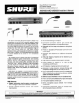
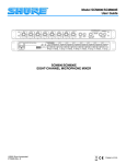
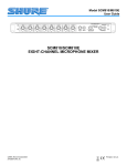
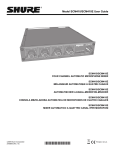
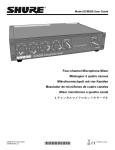
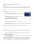
1
Model AMS8100
User Guide
AMS8100
0
POW ER
0 +12
-30 -12
LIMITER
OUTPUT
6
4
8
2
0
1
2
3
4
5
6
7
8
-∞
MASTER
PHONES
AUX
AUTOMATIC MICROPHONE MIXER
NOTE
Shure AMS8100 Mixers are designed for use only with Shure AMS Condenser Microphones. Conventional condenser
or other microphones will not operate properly with the AMS8100.
27C8621 (CD)
©2003 Shure Incorporated
Printed in U.S.A.
! IMPORTANT SAFETY INSTRUCTIONS !
1.
2.
3.
4.
5.
6.
7.
8.
9.
10.
READ these instructions.
KEEP these instructions.
HEED all warnings.
FOLLOW all instructions.
DO NOT use this apparatus near water.
CLEAN ONLY with dry cloth.
DO NOT block any ventilation openings. Install in accordance with the manufacturer's instructions.
DO NOT install near any heat sources such as radiators, heat registers, stoves,
or other apparatus (including amplifiers) that produce heat.
DO NOT defeat the safety purpose of the polarized or grounding-type plug.
A polarized plug has two blades with one wider than the other. A grounding
type plug has two blades and a third grounding prong. The wider blade or
the third prong are provided for your safety. If the provided plug does not fit
into your outlet, consult an electrician for replacement of the obsolete outlet.
PROTECT the power cord from being walked on or pinched, particularly at plugs,
convenience receptacles, and the point where they exit from the apparatus.
11.
12.
13.
14.
15.
This symbol indicates that there are important operating and
maintenance instructions in the literature accompanying this unit.
ONLY USE attachments/accessories specified by the manufacturer.
USE only with a cart, stand, tripod, bracket, or table
specified by the manufacturer, or sold with the
apparatus. When a cart is used, use caution when
moving the cart/apparatus combination to avoid
injury from tip-over.
UNPLUG this apparatus during lightning storms or when unused for long periods of
time.
REFER all servicing to qualified service personnel. Servicing is required when the
apparatus has been damaged in any way, such as power-supply cord or plug is damaged, liquid has been spilled or objects have fallen into the apparatus, the apparatus
has been exposed to rain or moisture, does not operate normally, or has been
dropped.
DO NOT expose the apparatus to dripping and splashing. DO NOT put objects
filled with liquids, such as vases, on the apparatus.
This symbol indicates that dangerous voltage constituting a risk
of electric shock is present within this unit.
! CONSIGNES DE SÉCURITÉ IMPORTANTES !
1.
2.
3.
4.
5.
6.
7.
8.
9.
LIRE ces consignes.
CONSERVER ces consignes.
OBSERVER tous les avertissements.
SUIVRE toutes les consignes.
NE PAS utiliser cet appareil à proximité de l'eau.
NETTOYER UNIQUEMENT avec un chiffon sec.
NE PAS obstruer les ouvertures de ventilation. Installer en respectant les consignes du fabricant.
Ne pas installer à proximité d'une source de chaleur telle qu'un radiateur, une
bouche de chaleur, un poêle ou d'autres appareils (dont les amplificateurs) produisant de la chaleur.
NE PAS détériorer la sécurité de la fiche polarisée ou de la fiche de terre. Une
fiche polarisée comporte deux lames dont l'une est plus large que l'autre. Une
fiche de terre comporte deux lames et une troisième broche de mise à la terre.
La lame la plus large ou la troisième broche assure la sécurité de l'utilisateur. Si
la fiche fournie ne s'adapte pas à la prise électrique, demander à un électricien
de remplacer la prise hors normes.
10.
11.
12.
13.
14.
15.
Ce symbole indique que la documentation fournie avec
l'appareil contient des instructions d'utilisation et d'entretien
importantes.
PROTÉGER le cordon d'alimentation afin que personne ne marche dessus et que
rien ne le pince, en particulier au niveau des fiches, des prises de courant et du point
de sortie de l'appareil.
UTILISER UNIQUEMENT les accessoires spécifiés par le fabricant.
UTILISER uniquement avec un chariot, un pied, un trépied,
un support ou une table spécifié par le fabricant ou vendu
avec l'appareil. Si un chariot est utilisé, déplacer l'ensemble
chariot-appareil avec précaution afin de ne pas le renverser,
ce qui pourrait entraîner des blessures.
DÉBRANCHER l'appareil pendant les orages ou quand il ne sera pas utilisé pendant
longtemps.
CONFIER toute réparation à du personnel qualifié. Des réparations sont nécessaires
si l'appareil est endommagé de quelque façon que ce soit, comme par exemple : cordon ou prise d'alimentation endommagé, liquide renversé ou objet tombé à l'intérieur
de l'appareil, exposition de l'appareil à la pluie ou à l'humidité, appareil qui ne marche
pas normalement ou que l'on a fait tomber.
NE PAS exposer cet appareil aux égouttures et aux éclaboussements. NE PAS poser
des objets contenant de l'eau, comme des vases, sur l'appareil.
Ce symbole indique la présence d'une tension dangereuse
dans l'appareil constituant un risque de choc électrique.
! WICHTIGE SICHERHEITSHINWEISE !
1.
2.
3.
4.
5.
6.
7.
8.
9.
10.
Diese Hinweise LESEN.
Diese Hinweise AUFHEBEN.
Alle Warnhinweise BEACHTEN.
Alle Anweisungen BEFOLGEN.
Dieses Gerät NICHT in der Nähe von Wasser verwenden.
NUR mit einem sauberen Tuch REINIGEN.
KEINE Lüftungsöffnungen verdecken. Gemäß den Anweisungen des Herstellers einbauen.
Nicht in der Nähe von Wärmequellen, wie Heizkörpern, Raumheizungen,
Herden oder anderen Geräten (einschließlich Verstärkern) installieren, die
Wärme erzeugen.
Die Schutzfunktion des Schukosteckers NICHT umgehen. Bei Steckern für die
USA gibt es polarisierte Stecker, bei denen ein Leiter breiter als der andere ist;
US-Stecker mit Erdung verfügen über einen dritten Schutzleiter. Bei diesen
Steckerausführungen dient der breitere Leiter bzw. der Schutzleiter Ihrer
Sicherheit. Wenn der mitgelieferte Stecker nicht in die Steckdose passt, einen
Elektriker mit dem Austauschen der veralteten Steckdose beauftragen.
VERHINDERN, dass das Netzkabel gequetscht oder darauf getreten wird, insbesondere im Bereich der Stecker, Netzsteckdosen und an der Austrittsstelle
vom Gerät.
11.
12.
13.
14.
15.
Dieses Symbol zeigt an, dass gefährliche Spannungswerte,
die ein Stromschlagrisiko darstellen, innerhalb dieses Geräts
auftreten.
NUR das vom Hersteller angegebene Zubehör und entsprechende Zusatzgeräte verwenden.
NUR in Verbindung mit einem vom Hersteller angegebenen
oder mit dem Gerät verkauften Transportwagen, Stand, Stativ,
Träger oder Tisch verwenden. Wenn ein Transportwagen verwendet wird, beim Verschieben der Transportwagen-GeräteEinheit vorsichtig vorgehen, um Verletzungen durch Umkippen
Das Netzkabel dieses Geräts während Gewittern oder bei längeren Stillstandszeiten
aus der Steckdose ABZIEHEN.
Alle Reparatur- und Wartungsarbeiten von qualifiziertem Kundendienstpersonal
DURCHFÜHREN LASSEN. Kundendienst ist erforderlich, wenn das Gerät auf
irgendwelche Weise beschädigt wurde, z.B. wenn das Netzkabel oder der
Netzstecker beschädigt wurden, wenn Flüssigkeiten in das Gerät verschüttet wurden
oder Fremdkörper hineinfielen, wenn das Gerät Regen oder Feuchtigkeit ausgesetzt
war, nicht normal funktioniert oder fallen gelassen wurde.
Dieses Gerät vor Tropf- und Spritzwasser SCHÜTZEN. KEINE mit Wasser gefüllten
Gegenstände wie zum Beispiel Vasen auf das Gerät STELLEN.
Dieses Symbol zeigt an, dass das diesem Gerät beiliegende
Handbuch wichtige Betriebs- und Wartungsanweisungen enthält.
2
! INSTRUCCIONES IMPORTANTES DE SEGURIDAD !
1.
2.
3.
4.
5.
6.
7.
8.
9.
LEA estas instrucciones.
CONSERVE estas instrucciones.
PRESTE ATENCION a todas las advertencias.
SIGA todas las instrucciones.
NO utilice este aparato cerca del agua.
LIMPIESE UNICAMENTE con un trapo seco.
NO obstruya ninguna de las aberturas de ventilación. Instálese según lo
indicado en las instrucciones del fabricante.
No instale el aparato cerca de fuentes de calor tales como radiadores, registros
de calefacción, estufas u otros aparatos (incluyendo amplificadores) que
produzcan calor.
NO anule la función de seguridad del enchufe polarizado o con clavija de
puesta a tierra. Un enchufe polarizado tiene dos patas, una más ancha que la
otra. Un enchufe con puesta a tierra tiene dos patas y una tercera clavija con
puesta a tierra. La pata más ancha o la tercera clavija se proporciona para su
seguridad. Si el tomacorriente no es del tipo apropiado para el enchufe, consulte a un electricista para que sustituya el tomacorriente de estilo anticuado.
10.
11.
12.
13.
14.
15.
Este símbolo indica que la unidad contiene niveles de voltaje
peligrosos que representan un riesgo de choques eléctricos.
PROTEJA el cable eléctrico para evitar que personas lo pisen o estrujen, particularmente en sus enchufes, en los tomacorrientes y en el punto en el cual sale del
aparato.
UTILICE únicamente los accesorios especificados por el fabricante.
UTILICESE únicamente con un carro, pedestal, trípode,
escuadra o mesa del tipo especificado por el fabricante o vendido con el aparato. Si se usa un carro, el mismo debe moverse con sumo cuidado para evitar que se vuelque con el
aparato.
DESENCHUFE el aparato durante las tormentas eléctricas, o si no va a ser utilizado
por un lapso prolongado.
TODA reparación debe ser llevada a cabo por técnicos calificados. El aparato
requiere reparación si ha sufrido cualquier tipo de daño, incluyendo los daños al
cordón o enchufe eléctrico, si se derrama líquido sobre el aparato o si caen objetos
en su interior, si ha sido expuesto a la lluvia o la humedad, si no funciona de modo
normal, o si se ha caído.
NO exponga este aparato a chorros o salpicaduras de líquidos. NO coloque objetos
llenos con líquido, tales como floreros, sobre el aparato.
Este símbolo indica que la literatura que acompaña a esta
unidad contiene instrucciones importantes de funcionamiento
y mantenimiento.
! ISTRUZIONI IMPORTANTI PER LA SICUREZZA !
1.
2.
3.
4.
5.
6.
7.
8.
9.
EGGETE queste istruzioni.
CONSERVATE queste istruzioni.
OSSERVATE tutte le avvertenze.
SEGUITE tutte le istruzioni.
NON usate questo apparecchio vicino all'acqua.
PULITE l'apparecchio SOLO con un panno asciutto.
NON ostruite alcuna apertura per l'aria di raffreddamento. Installate l'apparecchio seguendo le istruzioni del costruttore.
NON installate l'apparecchio accanto a fonti di calore quali radiatori, aperture
per l'efflusso di aria calda, forni o altri apparecchi (amplificatori inclusi) che generino calore.
NON modificate la spina polarizzata o con spinotto di protezione. Una spina polarizzata è dotata di due lame, una più ampia dell'altra. Una spina con spinotto è dotata di due lame e di un terzo polo di messa a terra. La lama più ampia ed il terzo
polo hanno lo scopo di tutelare la vostra incolumità. Se la spina in dotazione non si
adatta alla presa di corrente, rivolgetevi ad un elettricista per far eseguire le modifiche necessarie.
10.
11.
12.
13.
14.
15.
Questo simbolo indica la presenza di alta tensione all'interno
dell'apparecchio, che comporta il rischio di folgorazione.
EVITATE di calpestare il cavo di alimentazione o di comprimerlo, specie in corrispondenza di spine, prese di corrente e punto di uscita dall'apparecchio.
USATE ESCLUSIVAMENTE i dispositivi di collegamento e gli accessori specificati
dal costruttore.
USATE l'apparecchio solo con carrelli, sostegni, treppiedi,
staffe o tavoli specificati dal costruttore o venduti insieme
all'apparecchio stesso. Se usate un carrello, fate attenzione
durante gli spostamenti per evitare infortuni causati da un
eventuale ribaltamento del carrello stesso.
SCOLLEGATE l'apparecchio dalla presa di corrente in caso di temporali o di non utilizzo per un lungo periodo.
RIVOLGETEVI a personale di assistenza qualificato per qualsiasi intervento. È necessario intervenire sull'apparecchio ogniqualvolta sia stato danneggiato, in qualsiasi
modo, ad esempio in caso di danneggiamento di spina o cavo di alimentazione, versamento di liquido sull'apparecchio o caduta di oggetti su di esso, esposizione
dell'apparecchio a pioggia o umidità, funzionamento irregolare o caduta.
NON esponetelo a sgocciolamenti o spruzzi. NON appoggiate sull'apparecchio
oggetti pieni di liquidi, ad esempio vasi da fiori.
Questo simbolo indica la presenza di istruzioni importanti per
l'uso e la manutenzione nella documentazione in dotazione
all'apparecchio.
3
SHURE AMS8100
DESCRIPTION
The AMS8100 is designed for numerous applications in
sound reinforcement, audio recording, and broadcast. In any
speech pickup application where multiple microphones are required, the AMS8100 dramatically improves audio quality. Automatic operation allows an individual talker’s voice to rise
above background noise and reverberation to become clearer
and more intelligible.
The Shure Model AMS8100 is an automatic microphone
mixer using Shure’s patent--pending Directional IntellimixÒ circuitry. Directional Intellimix activates only those microphones
being addressed, minimizing the poor audio caused by multiple open microphones. The special patented* AMS microphones gate on only for sounds arriving from in front of the microphone within a 120_ “acceptance angle”. Additionally, if a
talker’s voice originates within the acceptance angle of more
than one AMS microphone, Directional Intellimix will activate
only the closest, loudest microphone. Directional Intellimix,
however, does not limit the number of open microphones to
one; if several talkers speak simultaneously, Directional Intellimix will activate several microphones.
The AMS8100 can handle up to eight AMS microphones
and two aux--level sources. The AMS8100 microphone inputs
work only with Shure AMS microphones. Each microphone input channel has a two-band equalizer. Equalization is useful to
reduce unwanted low-frequency audio pickup, as well as to
make the different AMS microphones—lavalier, surface-mount, probe and gooseneck—sound similar in their different
applications. Each input channel has three associated logic
terminals: Gate Out, Mute In, and Override In. These connections provide for activation of external devices and external microphone control, important for specialized installed sound applications. Each mixer channel also has a 1/4-inch phone jack
for use as a direct output. This jack can be modified to be a
gated channel output or a send/receive insert point.
The AMS8100 is capable of being expanded for installations as large as 400 input channels. The AMS8100 is fully
link--compatible with Shure’s SCM810 and FP410 automatic
mixers. The single-rack-height chassis is ideal for installations
with limited rack space. The removable header-type input and
output connectors are quick, convenient, and eliminate the
time and expense of wiring XLR microphone connectors.
The AMS8100 is designed for 100--120 Vac operation and
its line cord contains a standard American 3-pin grounded ac
plug. The AMS8100E is designed for 220--240 Vac operation
and its line cord contains a CEE 7/7 (“Schuko”) plug. An accessory rack panel adapter to convert the removable block input
and output connectors to XLR connectors, and aux connectors to phono jacks is available as the RKC800.
FEATURES
· Reliable, quick-acting, noise-free microphone activation
· Quick setup -- no threshold settings to adjust
· Direction--sensitive gating activates microphones only for
sounds originating within 120_ acceptance angle
· MaxBus allows gating of only one microphone per talker,
while allowing gating of multiple microphones for multiple
talkers
· Last Mic Lock-On circuit maintains ambient sound
· Automatic gain reduction as additional microphones are activated (NOMA: Number of Open Microphones Attenuator)
· Adjustable EQ per channel: low-frequency rolloff and highfrequency shelving
· Bi-color LED indication of channel activation and clipping
· Removable block screw connectors for quick and easy connection of microphones
· Link--compatible with SCM810 and FP410 automatic mixers
· Linking capability for systems up to 400 microphones
· Non-automatic aux-level inputs with level control
· Front-panel headphone output with level control
· Peak-responding output limiter with selectable thresholds
and LED indicator
· 100--120 V operation or 220--240 V operation, selectable
via internal switch.
· AMS8100: UL and cUL listed under UL813 and CSA C22.2
No. 1.
· AMS8100E: Conforms to European Union directives, eligible to bear CE marking; VDE GS-Certified to EN 60 065;
meets European Union EMC Immunity Requirements (EN
50 082--1, 1992).
NOTE
Shure AMS8100 Mixers are designed for use only with Shure AMS Condenser Microphones. Conventional condenser or
other microphones will not operate properly with the AMS8100.
*U.S. Patent #4,489,442
English -- 5
CONTENTS
Description . . . . . . . . . . . . . . . . . . . . . . . . . . . . . . . . . . . . . . . . . . . . . . . . . . . . . . . . . . . . . . . . . . . . . . . . . . . . . . . . . . . . 5
Features . . . . . . . . . . . . . . . . . . . . . . . . . . . . . . . . . . . . . . . . . . . . . . . . . . . . . . . . . . . . . . . . . . . . . . . . . . . . . . . . . . . . . . . 5
Contents . . . . . . . . . . . . . . . . . . . . . . . . . . . . . . . . . . . . . . . . . . . . . . . . . . . . . . . . . . . . . . . . . . . . . . . . . . . . . . . . . . . . . . . 6
Operating Principles . . . . . . . . . . . . . . . . . . . . . . . . . . . . . . . . . . . . . . . . . . . . . . . . . . . . . . . . . . . . . . . . . . . . . . . . . . . . 7
Front Panel . . . . . . . . . . . . . . . . . . . . . . . . . . . . . . . . . . . . . . . . . . . . . . . . . . . . . . . . . . . . . . . . . . . . . . . . . . . . . . . . . . . . 8
Rear Panel . . . . . . . . . . . . . . . . . . . . . . . . . . . . . . . . . . . . . . . . . . . . . . . . . . . . . . . . . . . . . . . . . . . . . . . . . . . . . . . . . . . . . 9
AMS Microphones . . . . . . . . . . . . . . . . . . . . . . . . . . . . . . . . . . . . . . . . . . . . . . . . . . . . . . . . . . . . . . . . . . . . . . . . . . . . . 10
Dip Switches . . . . . . . . . . . . . . . . . . . . . . . . . . . . . . . . . . . . . . . . . . . . . . . . . . . . . . . . . . . . . . . . . . . . . . . . . . . . . . . . . . 11
Setup . . . . . . . . . . . . . . . . . . . . . . . . . . . . . . . . . . . . . . . . . . . . . . . . . . . . . . . . . . . . . . . . . . . . . . . . . . . . . . . . . . . . . . . . . 12
Mixer Linking . . . . . . . . . . . . . . . . . . . . . . . . . . . . . . . . . . . . . . . . . . . . . . . . . . . . . . . . . . . . . . . . . . . . . . . . . . . . . . . . . . 14
Specifications . . . . . . . . . . . . . . . . . . . . . . . . . . . . . . . . . . . . . . . . . . . . . . . . . . . . . . . . . . . . . . . . . . . . . . . . . . . . . . . . . 16
Advanced Functions . . . . . . . . . . . . . . . . . . . . . . . . . . . . . . . . . . . . . . . . . . . . . . . . . . . . . . . . . . . . . . . . . . . . . . . . . . . 17
English -- 6
OPERATING PRINCIPLES
The AMS8100 is designed for use in a wide variety of multiple microphone speech applications. It is an audio processor
that activates only the microphones that are being addressed.
The operational concept behind the AMS8100 is called Directional IntelliMixÒ. It delivers seamless automatic mixing via a
unique combination of features:
· AMS direction--sensitive microphones
· MaxBus
· Last Mic Lock-On
· NOMA
An AMS direction--sensitive microphone will activate only
for sounds which originate within a 120_ acceptance angle in
front of the microphone. Other sounds outside of the 120_ acceptance angle, including speech, background noise, and reverberation, will not gate the microphone on, regardless of level.
MaxBus eliminates the poor audio quality that results
when a talker is picked up by more than one microphone. It
does this by controlling the number of microphones that may
activate for a single sound source. With MaxBus, one talker
will activate only one AMS8100 channel, even if multiple microphones are “hearing” that talker. However, Maxbus allows
multiple channels to activate simultaneously for multiple talkers. See the illustrations below. The illustration on the left
shows how an AMS4000 or AMS8000 gates microphones for
two talkers — by automatically gating on any microphones that
pick up a talker within the 120_ acceptance angle. The illustration on the right shows how MaxBus operates in the AMS8100
—even though the talkers are within the acceptance angle of
several microphones, only one microphone will activate for
each talker.
Last Mic Lock-On maintains a seamless audio mix by
keeping the most recently activated microphone open until a
newly activated microphone takes its place. Without Last Mic
Lock-On, a long pause in conversation will cause all microphones to turn off, and it may sound as if the audio signal has
been lost. Last Mic Lock-On ensures that background ambiance will always be present. (This feature can be defeated via
DIP switch on the rear panel.)
WITHOUT MaxBus
(AMS8000)
NOMA (Number of Open Microphones Attenuator) automatically reduces the gain of the mixer as additional microphones are activated. In a sound reinforcement application, if
the system gain is set below the feedback point with a single
microphone gated on, the increase in system gain with additional “on” microphones could cause feedback. NOMA prevents this by automatically reducing all “on” microphone gains
by 3 dB as additional microphones are gated on. This maintains constant total system gain, avoiding feedback and permitting the maximum microphone gains at all times. Also, this
consistency of system gain means that pickup of room noise
and reverberation also remains constant at the level of a single
microphone. (Note: NOMA is not the same as an automatic
gain control [AGC] and does not adjust input levels based on
loud or soft talking.)
Multiple miking situations—with several talkers participating—have always presented problems for the audio technician. If too few mics are used, the coverage of each talker may
vary, with one talker (nearest the mic) being louder and clearer
than the next. Talkers farthest from the mics will sound
“echoey” and reverberant, as very little of their direct sound
reaches the microphones. If too many mics are used, there’s
more background noise and reverberation pickup, as well as
less gain before feedback with a sound reinforcement (PA)
system.
It’s similar to having multiple video cameras all focused on
the same subject. If these camera signals are combined, the
result is a blurred image. When multiple microphones are open
for a single talker, the result is a blurred audio signal. It’s often
not practical for someone to turn mics on when they are needed and off when they are not. The AMS8100 automatic microphone mixer solves these problems.
The AMS8100 automatically attenuates (turns down) any
microphone not being used, greatly reducing the excess reverberation and feedback problems associated with the use of
conventional multiple microphone and mixer techniques.
When a new talker starts to speak, the AMS8100 immediately
selects and silently activates the most appropriate microphone within 4 milliseconds. Directional IntelliMix signal processing enables the AMS8100 to provide clear, natural voice
pickup. The AMS8100 significantly reduces the problems of
“hollow” or “muddy” sound, and insufficient gain before feedback.
*Shaded areas indicate
microphones gating on.
English -- 7
WITH MaxBus
(AMS8100)
FRONT PANEL
Î
Ê Ë
Ð
Ñ
Ó
AMS8100
4
2
8
0
Ì
4
6
1
10
6
2
4
8
0
2
10
4
6
2
8
0
3
10
6
2
4
8
0
4
10
6
2
4
8
0
5
10
6
2
8
0
6
10
6
2
4
8
0
7
10
Í
6
2
LIMITER
8
0
8
10
Microphone Channel Gain Controls 1 - 8. Allows adjustment of microphone gain.
Ë
Input LED 1 - 8. Lights green when channel is active;
lights red at 6 dB below clipping level.
Ì
Low-Cut Filter 1 - 8. Recessed screwdriver adjustment
provides adjustable low-frequency rolloff (high pass) to
reduce undesirable low-frequency signals.
Í
High-Frequency Shelving Filter 1 - 8. Recessed screwdriver adjustment provides level boost or cut in mid/highfrequency region for compensation of off-axis microphones, or for cutting the high-frequency sibilance of microphones.
AUX Level Control. Sets the input level for aux-level
equipment connected to the adjacent 1/4-inch phone jack
INPUT or rear-panel 1/4-inch AUX input.
POWER
-30 -12 0 +12
AUX
Ï
Ê
Î
4
INPUT
+20
MASTER
PHONES
Ò
Ï
Aux INPUT 1/4-inch Phone Jack. Mixes external auxiliary- or line-level sources, i.e., tape recorders, into output.
This input is not automatic. Signal appears at output of all
linked mixers. Unbalanced input: Tip = input, Ring = input.
Tip and Ring sum together.
Ð
MASTER Level Control. Determines the overall output
level.
Ñ
Output Level Meter. Nine-segment LED meter indicates
peak output signal level. Last LED indicates limiter action.
Ò
PHONES Control and 1/4-inch Phone Jack. Permits
monitoring of mixer output through headphones.
PHONES control determines headphone output level.
Ó
POWER LED. Lights green when unit is powered.
English -- 8
REAR PANEL
Ê
Ë
Ì
Ï
Í
Ê
Ë
Ò
Î
Ñ
Power Connector and Rocker Switch. Switch turns
unit on when power cord is plugged into AC mains. Can be
internally switched for 100--120 Vac or 220--240 Vac operation (see Voltage Selection).
Ï
OUTPUT LEVEL Switch. Switches between +4 dBu
(line), --10 dBV (aux), and mic level output. Switch is located behind OUTPUT connector.
Ð
DIRECT OUT 1/4-inch Phone Jacks. Provides nongated aux-level signal from each channel. Direct outs are
wired pre-fader and pre-EQ. Can be modified for use as a
gated channel output, or a send/receive insert point. (see
Internal Modifications).
Microphone Logic. DB-25 male connector provides
connection to each channel’s logic terminals. GATE OUT,
MUTE IN, and OVERRIDE IN logic terminals are available for each channel. Logic allows the AMS8100 to perform additional functions, such as cough buttons and remote LED status indicators (see Suggested Logic Applications). NOTE: THIS IS NOT AN RS-232 PORT.
Ì
DIP Switch. The 7-position DIP switch provides setup
options for the mixer (see DIP Switches).
Í
LINK IN/OUT Jacks.
Permit multiple AMS8100,
SCM810, or FP410 mixers to be stacked for additional inputs. Up to 50 AMS8100 mixers can be linked. For linking
to AMS8000 or AMS4000, see Mixer Linking.
Î
OUTPUT Removable Block Connector. Active balanced output signal for connection to amplifiers, recorders or other mixers. Pin 1 = hot (+), Pin 2 = cold (--), Pin 3 =
ground. If connecting to an unbalanced input, connect pin
2 (--) to pin 3 (ground).
Ð
As Direct out:
Unbalanced
Tip = output
Ring = not connected
Sleeve = ground.
As AUX input:(channel 8 only):
Unbalanced
Tip = input
Ring = input
Tip and Ring sum together.
Ñ
INPUT 1--8 Removable Block Connectors: For connection to AMS microphones only. Pin 1 = front cartridge
(red wire), Pin 2 = rear cartridge (black wire), Pin 3=
ground (shield).
Ò
AUX/D.O./D.O. 3-Position Slide Switch. Selects either
aux input function or direct output function for channel 8
(only) Direct Out jack. Left switch position is AUX IN; center and right positions are DIRECT OUT. Switch is located
behind Channel 8 Input connector.
English -- 9
AMS MICROPHONES
Description
AMS Microphones are gated on only by sounds which
come from within the 120° acceptance angle. Sounds which
reach the microphone from outside of that range, including
background noise, will not turn the microphone on no matter
how loud they are. See the illustrations below.
When an AMS microphone is directed so a talker is within
the 120° acceptance angle, the microphone will trigger on
when that talker speaks. Since the microphone is not triggered
by sounds from outside of that angle, the sound is clearer than
that of conventional sound reinforcement systems. When a
microphone is on, it operates as a cardioid microphone, or as a
hemi--cardioid in the case of the AMS22 low--profile microphones.
AMS microphones come in several models. Model
AMS22 is a low-profile surface--mount microphone. Model
AMS24 is a gooseneck microphone. Model AMS26 is a probe
microphone with a front pop-filter grille. Model AMS28 is a lavalier microphone.
XLR built in and a cable (as shown below) must be used to connect it to the AMS8100. This same type of cable can be used
as an extension cable between the AMS22 or AMS28 microphones and the AMS8100 mixer.
Under most circumstances, lengths of 150 meters (500 ft)
or greater of high quality, 2-conductor, shielded microphone
cable can be used between the microphone and the AMS mixer microphone input. The shield must be connected to both
ends of the cables. Good practice dictates that microphones
and cables be grounded only to the AMS mixer chassis ground
(pin 3 of the input connector).
Do not attempt to connect AMS microphones to standard
phantom-powered inputs; they will not function properly.
Placement
Connections
Use low--profile AMS22 boundary microphones on tables
and desks; use permanently mounted AMS24 gooseneck microphones on tables, desks, or lecterns; use AMS26 probe microphones on floor or desk stands, or goosenecks; use
AMS28 lavalier microphones where the talker must have freedom of movement.
The AMS8100 utilizes removable block connectors for
connecting the microphones. The AMS4000 and AMS8000
utilize XLR connectors for microphone connection. The newer
block-style, screw connectors offer faster and more convenient connection than soldering XLR connectors.
Locate the microphones so that intended sources are
within 60° of either side of the front of the microphone; that is,
within the 120° acceptance angle angle (see illustrations below). Sources of undesired sound should be located outside
the 120° acceptance angle.
The AMS22 and the AMS28 come supplied with XLR connectors already attached. Three options are available for connecting these microphones to the AMS8100. First, you can cut
off the XLR connector from the microphone cable, strip the individual wires, then slip them into the supplied block connectors. Second, the Shure RKC800 (purchased separately) can
be used to adapt up to eight (8) XLR connectors to pre-wired
block connectors suitable for the AMS8100. Third, an extension cable (as shown below) can be used to connect an AMS
microphone.
The closer the microphones are to their sound sources,
the greater the loudness of the sound system before feedback
occurs. Likewise, the farther the microphones are from loudspeakers, the louder the sound system can get before feedback occurs. These distances have a well-defined effect on
system gain before feedback, as described by the Potential
Acoustic Gain (PAG) equation. For more information on the
PAG equation, contact Shure’s Applications Group at
847--866--2525.
The AMS24 gooseneck microphone is supplied without
an XLR connector, and can be wired directly to the block connector. The AMS26 is a probe-style microphone which has an
Sound reflections from a hard surface can hamper proper
gating. Each microphone should be at least 1 meter (3 ft) from
the wall behind it, and at least 0.3 meters (1 ft) from objects behind it, such as briefcases.
AMS24
120 o
AMS26
AMS22
AMS28
PIN 2 +
(RED)
PIN 1
(SHIELD)
PIN 2 -(BLACK)
PIN 1 +
(RED)
+
TO AMS MICROPHONE
PIN 3 -(BLACK)
XLR TO BLOCK CONNECTOR
English --10
PIN 3
SHIELD
--
AMS
MICROPHONE
INPUT
DIP SWITCHES
The rear-panel DIP switch provides the following setup
options. The positions shown in bold type are the factory settings.
(MIXER
REAR
PANEL)
NOTE: Switch positions and effects are shown in the illustration below and also on the mixer label.
DIP SWITCH SW902
1 2 3 4 5 6 7
DIP SWITCH SW902 FUNCTIONS
Switch
Function
Manual/Auto
Last Mic
Lock-On
Hold Time
Off-Attenuation
Level
Limiter
Threshold
Link
Local/Global
Switch Position
Number®
1
2
3
4
5,6
7
5 Up
6 Up
5 Down
6 Up
Switch Up
Auto
On
0.4 second
15 dB
5 Up
6 Down
5 Down
6 Down
Switch Down
Manual
All mics off after
hold time
¥ (completely
1.0 second
off)
Manual/Auto: Automatic activation is defeated in the
Manual position. In Manual mode, the AMS8100 functions as a
standard 8x1 mixer.
Last Mic Lock-On: Last Mic Lock-On feature keeps the
most recently activated microphone turned on until a newly activated microphone takes its place. When defeated, microphones turn off after their preset hold time.
Hold Time: Adjusts the time an activated microphone
(which is not locked on) remains on after the talker stops talking. Settings are 0.4 seconds or 1.0 second.
= Limiter off
= +8 dBu
Global
= +16 dBu
= +4 dBu
Local
Off-Attenuation: Changes the off-attenuation level from
15 dB to infinity (¥). With the 15 dB setting, an unused microphone is 15 dB lower in level than when it is activated. With the
¥ setting, an unused microphone is completely off.
Limiter Threshold: Changes the output limiter threshold.
Settings are OFF (factory setting), +16 dBu, +8 dBu, or +4 dBu
(see Internal Modifications for other threshold settings).
Link Global/Local: Determines whether each linked
AMS8100 output contains only its own program output, or that
of all linked mixers (see Mixer Linking for more information).
English --11
SETUP
MOUNTING
To mount the AMS8100 in a rack-mount in a standard
19-inch audio equipment rack, install the mixer using the sup-
plied Phillips head screws through each side panel. Use all
four screws.
CONNECTIONS
Make audio connections as follows:
3. If additional AMS8100 mixers are to be linked to increase
the number of microphone inputs, connect them by
means of the Link In and Link Out jacks. Connect the LINK
OUT of the first mixer to the LINK IN of the next mixer, and
so on. Leave the LINK IN jack of the first mixer and the
LINK OUT jack of the last mixer unconnected. NOTE:
These jacks are for linking only, not for audio inputs or outputs (see Figure 5).
TO STEREO OR MONO HEADPHONES
FROM AUX-- OR LINE--LEVEL SOURCE
TO AMP/REC/MIXER INPUT (CH. 1--7)
FROM AMS MICS (CH. 1--8)
TO AMP/RECORD/MIXER INPUT
OR FROM AUX SOURCE (CH. 8)
MIXER OUTPUT TO AMP/REC/MIXER INPUT
TO LINKED AMS8100 MIXERS
TO ADVANCED FUNCTION WIRING
TO AC POWER SOURCE
AUDIO CONNECTIONS
1. Connect an AMS microphone to the Channel Input connectors (use high-quality 2-conductor shielded cables). It
is important to connect the red wire from the AMS microphone cable to the first pin of the block connector, the
black wire to the second pin of the block connector, and
the shield to the last pin of the block connector.
2. Connect the AMS8100 Line Level Output to the input of
mixers, EQs, amplifiers or recorders.
LINKING MIXERS
4. For headphone monitoring, connect headphones to the
front-panel 1/4-inch PHONES jack.
5. Connect the power cord to the appropriate power source.
If the operating voltage is to be changed, refer to the Voltage Selection section.
CONTROL SETTINGS
1. Turn on the Power switch.
2. Adjust each channel level so that its Overload LED flickers only during very loud speech.
3. Adjust the Low-Cut and High-Frequency controls adjacent to each Input Gain control to make each microphone
sound similar.
4. Adjust the AMS8100 Master level control for the required
output level, as indicated by the output peak meter.
5. Adjust the headphone volume level with the PHONES
control knob.
6. The AMS8100 is now ready for operation.
English --12
EQUALIZER
Low Cut Filter (High-Pass)
+2
The low-cut (or high-pass) filter allows all frequencies
above its cutoff point to pass from filter input to filter output
without attenuation, while frequencies below the cutoff are attenuated (see right). The cutoff point is defined as the frequency where the signal has dropped 3 dB relative to the flat, or
bandpass, region. Below the cutoff point, the filter exhibits increasingly more attenuation as the frequency diminishes. The
AMS8100 has an adjustable-frequency, low-cut (high-pass)
filter of 6 dB per octave.
Low-cut filters are ideally used for attenuating, or rolling
off, the audio signal where extraneous noise, excessive proximity effect, or other unwanted material is present. For example, the low-frequency vibration cause by footsteps and vehicle traffic can be transmitted through microphone stands to
the microphone, and then into the sound system. These frequencies, typically ranging from 5 to 80 Hz, are generally not
desirable.
FULL CW
0
-2
-4
-6
FULL CCW
-8
-10
20
100
50%
ROTATION
1,000
5,000
FREQUENCY (Hz)
LOW-CUT FILTER EFFECTS
+10
FULL
CW
+8
+6
+4
+2
High-Frequency Shelving
The fixed-frequency equalizer produces a 6 dB boost or
cut at 5 kHz and above (see right). High-frequency shelving is
extremely useful for boosting flat frequency response, tempering very sibilant vocal microphones, or enhancing the sound of
off-axis lavalier microphones.
50%
ROTATION
0
-2
-4
-6
-8
-10
200
FULL
CCW
1,000
FREQUENCY (Hz)
10,000 20,000
HIGH-FREQUENCY SHELVING EFFECTS
LIMITER
The AMS8100 has a peak output limiter that prevents distortion during loud program peaks without affecting normal
program levels. Increasing the individual or Master level controls will increase the average output and, in turn, the amount
of limiting. A limiter prevents excessive overloading of devices
connected to the AMS8100 output. As supplied, the limiter is
defeated. The limiter threshold is selectable for a peak output
level of +4, +8, or +16 dBu. For instance, with the threshold set
at +16 dBu, the mixer would have 12 dB of headroom with a
nominal level of +4 dBu. The limiter thresholds can be changed
from their factory settings as described in the Internal Modifications section.
USING AN EQUALIZER/FEEDBACK CONTROLLER WITH AN AUTOMATIC MIXER
When setting up a sound system which has an outboard
equalizer or feedback controller in the signal chain, set the
AMS8100 to MANUAL. This activates all microphone inputs,
so every possible feedback path is open. With the AMS8100 in
MANUAL mode, equalize the sound system and/or “Ring Out”
the room to set the feedback controller.
After equalization is complete, set the AMS8100 to
AUTOMATIC mode. Remember that the input of an automatic
mixer drops by 3 dB every time the number activated inputs
doubles. When using an AMS8100 in MANUAL mode, the
master output drops by 9 dB when all 8 inputs are activated.
Conversely, it will rise by 9 dB when switched back to AUTOMATIC mode.
English --13
MIXER LINKING
Linking Multiple AMS8100 Mixers
Linking an AMS8100 to AMS8000/AMS4000
The AMS8100 provides eight input channels. If additional
inputs are needed, more AMS8100 mixers (as many as 50)
can be “linked” using supplied link cables. A setup like this can
provide up to 400 mic inputs.
To link the AMS8100 with AMS8000 or AMS4000 mixers,
a special cable must be constructed by the installer (see below). Use high quality, 2-conductor, shielded cable. It is important to connect the mini-DIN connector to the AMS8100’s LINK
IN and the 1/4-in. connectors to the AMS8000 or AMS4000
LINK OUT connector. When linked, the last--mic lock--on and
MaxBus will function on the AMS8100, but not the
AMS8000/AMS4000, as the AMS8000/AMS4000 do not contain circuitry for these functions. The direction--sensitive gating and the NOMA functions will be unaffected and work between linked mixers as before.
As long as the link jacks of all mixers are connected (outto-in, sequentially, leaving one Link In and one Link Out jack
unconnected), the automatic mixing functions will be shared
by all units. All input signals appear at all linked mixer outputs.
There is no master/slave relationship.
The output controls and functions of each linked mixer are
post-link and do not affect the signals appearing at other linked
mixer outputs. Each mixer’s Master level control only controls
its own output. Each output can be used independently.
NOTE: The actual off-attenuation in the 15 dB switch position
increases slightly as more mixers are linked. This reduces excessive noise and reverberation contributed by the increased
number of attenuated microphones.
In a linked system, the Aux input of any mixer appears at
each linked mixer’s output. See Internal Modifications to defeat the linking of Aux signals.
IMPORTANT: When using the logic terminals on linked
mixers, connect the Channel 8 LOGIC GROUND terminals of
each unit together. Switching clicks may result if this is not
done.
Linking AMS8100 to Shure SCM810 or FP410
The AMS8100 is fully link--compatible with Shure mixers
utilizing Intellimix, such as the SCM810 or the FP410. When
linked, the last--mic lock--on, MaxBus, and NOMA will work
seamlessly with the other mixers. The direction--sensitive gating portion of the AMS8100 will function with its microphones,
and the Noise Adaptive Threshold portion of the Intellimix mixer will function with the microphones connected to it.
Room Combining
To connect and disconnect two AMS8100s for room combining purposes, such as may be needed in a partitioned room,
switches or relays must be inserted in series with the link cable
conductors. To accomplish this, all eight conductors within the
link cable must be independently switched, each with a SPST
switch or relay. Alternatively, an 8PST switch or relay may be
used. When the switch is closed, the mixers will be actively
linked. When it is open, the mixers will operate independently.
Extended Link Cables
As the link connections in the AMS8100 are unbalanced,
care must be taken when using longer link cables to avoid hum
and noise problems. High quality, shielded cable should be
used and the cables should be kept away from sources of
magnetic or electrical noise, such as large power transformers
or light dimmers. Additionally, linked mixers should be powered from the same AC mains circuit to minimize ground currents. These factors determine the maximum cable length, but
cables under 2 m (6 ft) are generally not a problem.
TIP
LINK B
TO LINK B OUT
PIN 7
SLEEVE
TO
LINK IN
AMS8100
PIN 5
LINK A
PIN 1
TIP
GROUND/SHIELD
CABLE FOR LINKING AMS8100 MIXER TO AMS8000/AMS400 MIXER
English --14
SLEEVE
TO
LINK OUT
AMS8000
TO LINK A OUT
GLOBAL/LOCAL FUNCTIONS
The Global/Local switch selects which input channels appear at that linked mixer’s output. Set to the Global position, all
input channels from all linked mixers appear at that mixer’s
output. Set to the Local position, only its own eight input channels appear at that mixer’s output. The Master level control, in
any mode, only controls the level of its own output.
The Master level control is independent of the Global/Local switch. The output level of each mixer is affected only by its
own Master control. All automatic functions (such as Last Mic
Lock-on and MaxBus) are connected on all linked mixers and
are not affected by the Global/Local switch.
AMS8100 “C” (GLOBAL)
LINK
An example of the possibilities of this setup is shown in
Figure 8. Here two AMS8100s are set to Local, and the resulting sound distribution provides local sound reinforcement
while avoiding feedback. This is a simple “mix-minus” setup.
The third AMS8100 is set to Global and feeds a tape recorder,
At the same time, the automatic functions (Last Mic Lock-On,
etc.) remain common to all mixers. The following table summarizes the mixer settings.
Mixer
Link Global/
Local Switch
Audio Output
Contains...
A
Local
A
B
Local
B
C
Global
A, B, C
RECORDER
AMS8100 “A” (LOCAL)
AMS8100 “B” (LOCAL)
LOUDSPEAKER
LOUDSPEAKER
LINKED AMS8100 MIXERS
English --15
SPECIFICATIONS
Measurement Conditions (unless otherwise specified):
full gain; 1 kHz, one channel activated; with AMS26 microphone; terminations: Line 10 kW, Phones 300 W (tip-sleeve
and ring-sleeve), Direct Out 10 kW; Auto mode, equalization
controls adjusted for flat response
Frequency Response (Ref 1 kHz, channel controls centered)
80 Hz to 20 kHz ±2 dB; -3 dB corner at 50 Hz
Voltage Gain (typical, controls full clockwise)
Input
Mic
Aux
AMS26 mic
(72 dB SPL in)
Aux
--20
dBu
4 dB
Send/Return
--20
dB
+5
dBu
29
dB
5 dB
Inputs
Input
Output
Line
Headphone
+20
—
dBu
44
52 dB
dB
20
28 dB
dB
Impedance
Designed
Actual
for use
(typical)
with
Direct
Out
--38 dBu
—
—
Input
Clipping
Level
Mic
AMS Mics
only
400 W
Aux
£2 kW
£2 kW
10 kW
+132 dB
SPL
+24 dBu
100 kW
+20 dBu
Send/Return
Outputs
Output
Impedance
Designed
Actual
for use
(typical)
with
Output
Clipping
Level
Line
³600 W
60 W
+24 dBu
Headphone
8-200 W,
60 W recommended
1 kW
+6 dBu
Direct Out
>2 kW
1 kW
+18 dBu
Send/Re>2 kW
1 kW
+18 dBu
turn
Total Harmonic Distortion
<0.1% at +18 dBu output level, 80 Hz to 20 kHz (through 80
Hz-20 kHz filter; Input 1 and Master at 5, all other controls full
counterclockwise)
Hum and Noise
Equivalent Input Noise . . . . . . . . . 27 dB SPL (A-weighted)
Output Hum and Noise (through 20 Hz to 20 kHz filter; channel
controls full counterclockwise)
Master full counterclockwise . . . . . . . . . . . . . . . -90 dBu
Master full clockwise . . . . . . . . . . . . . . . . . . . . . . -65 dBu
Polarity
Positive pressure on AMS microphone diaphragm produces
positive voltage on pin 1 (+) with respect to pin 2 (--) at Output.
Send inputs to all outputs are non-inverting. AUX input to all
outputs is inverting.
Input Channel Activation
Attack Time . . . . . . . . . . . . . . . . . . . . . . . . . . . . . . . . . . . 4 ms
Hold Time . . . . . . . . . . . . . . . . . . . 0.4 s (switchable to 1.0 s)
Decay Time . . . . . . . . . . . . . . . . . . . . . . . . . . . . . . . . . . . 0.5 s
Off-Attenuation
15 dB (switchable to ¥)
Overload and Shorting Protection
Shorting outputs, even for prolonged periods, causes no damage. Microphone inputs are not damaged by signals up to 3 V;
Line and Monitor inputs by signals up to 20 V.
Equalization
Low-frequency . . . . . . . . . . . . . . 6 dB/octave cut, adjustable
corner from 50 to 300 Hz
High-frequency . . . . . . . . . . . . . . . . ±6 dB at 5 kHz, ±8 dB at
10 kHz, shelving
Limiter
Type . . . . . . . . . . . . . . . . . . . . . . . . . . . . . . . . . . . . . . . . . Peak
Threshold . . . . . . . . . . . . . . . . . Switchable: off, +4, +8, +16
(dBu at output)
Attack Time . . . . . . . . . . . . . . . . . . . . . . . . . . . . . . . . . . . 2 ms
Recovery Time . . . . . . . . . . . . . . . . . . . . . . . . . . . . . . . 300 ms
Indicator . . . . . . . . . . . . . . . . Lights red when limiting occurs
Input LEDs
Green on channel activation, red at 6 dB below clipping
Operating Voltage
AMS8100: 100--120 Vac, 50/60 Hz, 200 mA
AMS8100E: 220--240 Vac, 50/60 Hz, 100 mA
Temperature Range
Operating . . . . . . . . . . . . . . 0° to 60° C (32° to 135° F )
Storage . . . . . . . . . . . . . . . . -30° to 70° C (-20° to 165° F)
Overall Dimensions
44.5 mm H x 483 mm W x 317 mm D
(13/4 x 19 x 121/2 inches)
Net Weight
4.3 kg (9 lb 9 oz)
Replacement Parts
Knob, Channel Gain & Phones (white) . . . . . . . 95A8238
Knob, Master (gray) . . . . . . . . . . . . . . . . . . . . . . . 95C8238
Line (Power) Cord (AMS 8100) . . . . . . . . . . . . 95A8762
Line (Power) Cord (AMS8100E) . . . . . . . . . . . . 95A8247
Link Cable . . . . . . . . . . . . . . . . . . . . . . . . . . . . . . . 95A8889
Three -Terminal Block Connector . . . . . . . . . . . 95A8580
Certifications
AMS8100: UL and cUL listed under UL813, CSA C22.2 No.1
AMS8100E: Conforms to European Union directives, eligible to bear CE marking; VDE GS-Certified to EN 60 065;
meets European Union EMC Immunity Requirements (EN
50 082--1, 1992).
CE Certification Note: The extreme sensitivity of the Directional Intellimix circuitry may allow some channel gating due
to static discharge or abnormal electrical disturbance to the
power or signal lines. The unit will not be damaged: normal
operation will resume after the disturbance ceases.
Service Statement
For additional service or parts information, please contact
Shure’s Service department at 1-800-516-2525. Outside the
United States, please contact your authorized Shure Service
Center.
English --16
ADVANCED FUNCTIONS
The AMS8100’s Advanced Functions are recommended only for those who are technically knowledgeable and familiar
with audio electronics.
The logic functions of the AMS8100 expand the mixer’s
range of installation and control options. Logic can be used for
everything from simple cough switches to elaborate computercontrolled room systems. (Shure’s AMS Update publication
contains additional applications of advanced logic. This publication is available by contacting Shure’s Applications Group at
847--866--2525.) The following logic functions are available for
each channel:
GATE 1
GATE 3
GATE 5
GATE 7
LOGIC
MUTE 1
MUTE 3
MUTE 5
MUTE 7 GROUND
O’RIDE 2
GATE OUT: Follows channel gating and goes to logic
“low” (sinks current) when microphone is gated on. 500 mA of
current sinking ability is provided (see illustration A, below).
O’RIDE 6
MUTE 4
MUTE 6
O’RIDE 8
MUTE 8
GATE 8
GATE 6
GATE 4
GATE 2
O’RIDE 7
O’RIDE 5
O’RIDE 3
O’RIDE 1
+5 V
+5 V
LOGIC CONNECTOR
55K
10K
GATE
OUT
MUTE IN
OR
OVERRIDE
IN
TO
AMS8100
CIRCUIT
FROM
AMS8100
CIRCUIT
LOGIC
GROUND
A
MUTE 2
O’RIDE 4
B
LOGIC EQUIVALENT CIRCUIT DIAGRAMS
MUTE IN: Applying logic “low” (from GATE OUT or a
switch closure to logic ground) gates channel off (see Figure
9B). Channel output drops to -¥, regardless of Off Attenuation
setting.
OVERRIDE IN: Applying logic “low” (from GATE OUT or a
switch closure to logic ground) forces channel on (see illustration B, above). Factory setting provides that when both Mute
and Override are activated, Mute takes precedence (see Internal Modifications for Override precedence).
LOGIC GROUND: Logic ground is distinct from the
AMS8100 audio ground. Make all logic ground connections to
this pin, including power supply ground of external logic circuitry. To avoid switching clicks, do not connect logic ground to audio, chassis or rack grounds.
Logic controls are accessed at the DB-25 multi-pin connector on the rear panel (see illustration LOGIC CONNECTOR). The pin connections are given in the following
table.
LOGIC CONNECTIONS
Logic Function
GATE OUT1
GATE OUT 2
GATE OUT 3
GATE OUT 4
GATE OUT 5
GATE OUT 6
GATE OUT 7
GATE OUT 8
OVERRIDE IN 1
OVERRIDE IN 2
OVERRIDE IN 3
OVERRIDE IN 4
OVERRIDE IN 5
OVERRIDE IN 6
OVERRIDE IN 7
OVERRIDE IN 8
MUTE IN 1
MUTE IN 2
MUTE IN 3
MUTE IN 4
MUTE IN 5
MUTE IN 6
MUTE IN 7
MUTE IN 8
Logic Ground
English --17
Input
Channel
1
2
3
4
5
6
7
8
1
2
3
4
5
6
7
8
1
2
3
4
5
6
7
8
all
Connector Pin No.
1
15
4
18
7
21
10
24
14
3
17
6
20
9
23
12
2
16
5
19
8
22
11
25
13
SUGGESTED LOGIC APPLICATIONS
This section contains suggestions on the uses of the
AMS8100’s logic capabilities. Note that uses of these functions are not limited to the listed applications. The user is limited only by individual imagination and creativity. For additional
suggestions and solutions to installation problems, contact
Shure’s Applications Group at 847--866--2525.
In the following paragraphs, the wiring diagrams refer to
the DB-25 connector pins shown in Figure 10.
Cough Button
The talker can turn off his or her microphone during
coughing or private conversations by installing an SPST pushbutton switch between the MUTE IN and Logic Ground pins for
each channel to be modified (see illustration COUGH BUTTONS—Channels 1, 2 and 3 modified). When a channel is
muted, no audio is passed. (See “Dead Zone on MUTE IN Defeat” in Internal Modifications section for more information on
MUTE IN logic.)
Remote Channel-On Indicators
Remote indicators can be used to indicate when a talker’s
microphone is on. Connect the LEDs and a 5-volt supply to the
GATE OUT pins as shown in the illustration REMOTE CHANNEL-ON INDICATORS (Channels 1, 2 and 3 shown modified).
To avoid switching clicks in the audio output, do not ground the
power supply negative terminal in the audio system or rack
ground. IMPORTANT: If a single cable is used for the microphone audio signal and the LED dc power, separate shielded
pairs must be used. Failure to carry the dc power on a shielded
pair may result in audible clicking due to capacitive coupling
between the dc power lines and microphone lines.
+ 5 V POWER -SUPPLY
R
R
LOGIC
GROUND
G1
G3
LOGIC
GROUND
M1
M3
G2
R = 470 W , 1/4 W
REMOTE CHANNEL--ON INDICATORS
M2
Disabling the Gating Function (Bypass)
To keep certain microphones on at all times, wire the desired microphone channel’s OVERRIDE IN pins together to
the Logic Ground pin. The selected channels now function as
they would in a non-automatic mixer (see illustration GATING
BYPASS—Channels 1, 2 and 3 modified).
COUGH BUTTONS
Chairperson-Controlled Muting
The chairperson can, by activating a switch, silence all
other microphones and be heard without interruption. For operation in this mode, connect all the MUTE IN pins together except that of the chairperson’s channel, and wire an SPST
pushbutton or toggle switch between those MUTE IN pins and
Logic Ground pin (see illustration CHAIRPERSON—CONTROLLED MUTING—the chairperson is shown as Channel
1).
An alternative to a switch is to connect the chairperson’s
GATE OUT to the MUTE IN of other channels. When the chairperson’s microphone activates, all other microphones mute.
NOTE: If the chairperson’s microphone activates for any reason (cough, sneeze, etc.) all other microphones will be muted.
CH. 1
M3
M5
M7
LOGIC
GROUND
LOGIC
GROUND
O2
O1
O3
GATING BYPASS
Inhibiting Gating for Unwanted Sounds
As described in the Operating Principles section, MaxBus
attempts to activate only one microphone per sound source.
Muting a microphone channel prevents its audio from appearing at the mixer’s output. However, the muted microphone still
communicates with other mic channels via MaxBus. A sound
source picked up by a muted microphone will not activate other
microphones.
Sound sources that may cause unwanted microphone
channel activation include:
M2
M4
M6
CHAIRPERSON--CONTROLLED MUTING
· A noisy fax machine or printer
· A squeaky door
· A paging system loudspeaker
· An audio teleconferencing return signal loudspeaker
English --18
The AMS8100 can prevent these and similar sounds from
activating microphones by taking the following steps.
1. Place one microphone near the unwanted sound source.
Connect that microphone’s signal to a channel input,
2. Mute that channel using the logic terminal (see illustration
INHIBITING GATING FOR UNWANTED SOUNDS—
Channel 1 is muted).
3.
Adjust that channel’s gain control just to the level where
other microphones in the system do not activate for the
unwanted sound. If the channel gain is set too high, other
system microphones will be difficult to activate for desired
sounds. If set too low, unwanted sounds will continue to
activate other microphones.
LOGIC
GROUND
M1
“Filibuster” Mode
In normal operation, when several people talk, each microphone gates on so that no speech is missed. In “filibuster”
action, a microphone that is gated on prevents other microphones from gating on. Once a microphone has gated on, other microphones cannot gate on until the talker has paused long
enough for that microphone to gate off. Thus the person talking
has the floor and cannot be interrupted.
To establish this function, first perform the internal Mute to
“Inhibit” modification (see Internal Modifications). Then connect all the MUTE IN pins of the modified channels together, all
the GATE OUT pins of the modified channels together, and the
GATE OUT pin of one modified channel to the MUTE IN pin of
another modified channel (see illustration “FILIBUSTER”
MODE—Channels 1, 2 and 3 modified). Turn the Last Mic
Lock-On switch (SW902, position 2) to off.
NOTE: To prevent high-frequency oscillation, do not wire
a channel’s GATE OUT pin to its own MUTE IN pin unless the
Mute to “Inhibit” change has been made.
INHIBITING GATING FOR UNWANTED SOUNDS
Some applications require a loudspeaker to be placed
near each talker to provide audio reinforcement, or to permit
telephone conversation or conference monitoring. Each loudspeaker can cause feedback unless it is automatically
switched off when the talker near it speaks. To provide this
function, connect the GATE OUT terminal of each channel to a
separate loudspeaker muting relay as shown in illustration
LOUDSPEAKER MUTING (Channels 1, 3 and 5 shown modified). Recommended relays are Radio Shack 275--248, Omron G2R-14-DC12 (Digi-Key number Z745-ND), Potter &
Brumfield R10-E1Y2-V185 (Newark number 45F106), or
equivalent. NOTE: A diode across each relay coil is required to
suppress inductive voltage spikes which may damage the
AMS8100.
An existing sound system using 24-volt relays can be
used with the AMS8100 without modification if the relay coil
current draw is under 500 mA.
D
D
D
G2
LOGIC
GROUND
M2
“FILIBUSTER” MODE
Inhibit Function
See Internal Modifications.
Diode Isolation of Logic Controls
Two or more control functions using the same logic pins
can be isolated with diodes. In this manner a channel can be
muted by an overall group mute switch, or by its own cough
button (see illustration DIODE ISOLATION OF LOGIC CONTROLS—Channels 1, 3 and 5 modified).
+
12 V
POWER
SUPPLY
GROUP
MUTE
--
G3 G5
G1
G1
JUMPER
Loudspeaker Muting
G3
M1 M3
D = 1N4148 OR
EQUIVALENT
D
M1
LOGIC
GROUND
D
M3
D
M5
LOGIC
GROUND
COUGH
BUTTONS
D = 1N4148
LOUDSPEAKER MUTING
FROM
POWER
AMP
English --19
DIODE ISOLATION OF LOGIC CONTROLS
External Logic Devices
+
AMS8100 logic levels are directly compatible with TTL
and 5-volt CMOS logic families. For information on logic gate
use, refer to the TTL Cookbook and CMOS Cookbook, both by
D. Lancaster, Howard Sams Publishing Co.
15 V
POWER
SUPPLY
5.1 K
--
Mixer logic may be used with 15-volt CMOS logic if a pullup resistor is used with each GATE output (see illustration
15-VOLT CMOS—Channel 1 modified).
CMOS
GATES
Digital Controls or Microcomputers
LOGIC
GROUND
The AMS8100 logic pins can interface with custom-designed digital control circuitry or microcomputers for unlimited
possibilities of system control functions.
G1
M1
O1
15--VOLT CMOS
VOLTAGE SELECTION
The AMS8100 can be internally modified to operate from
220--240 Vac, 50/60 Hz power.
WARNING
Voltages in this equipment are hazardous to life.
No user-serviceable parts inside. Refer all
servicing to qualified service personnel.
The safety certifications of the AMS8100 do not
apply when the operating voltage is changed
from the factory setting.
To change the operating voltage, follow these steps.
1. Disconnect the AMS8100 from the ac power source.
2. Remove the eight Phillips head screws securing the top cover.
3. Locate Voltage Selector switch SW903 adjacent to power
transformer T901 and, using a screwdriver, turn the center
rotor to the 230 V position.
4. Locate Fuse F901 and remove it. Replace it with a 100 mA,
250 V, time delay fuse for 220--240-volt operation (200 mA,
250 V, slow-blow fuse for 100--120-volt operation).
Fuse part numbers are:
Fuse Type
Shure Part No.
Littelfuse Part
No.
100 mA, 250 V
80C258
218.100
200 mA, 250 V
80BC8196
239.200
Similarly, the AMS8100E can be internally modified to operate from 100--120 Vac, 50/60 Hz power.
To change the operating voltage, follow these steps.
1. Disconnect the AMS8100E from the ac power source.
2. Remove the eight Phillips head screws securing the top cover.
3. Locate Voltage Selector switch SW903 adjacent to power
transformer T901 and, using a screwdriver, turn the center
rotor to the 115 V position.
4. Locate Fuse F901 and remove it. Replace it with a 200 mA,
250 V, time delay fuse for 100--120-volt operation (100 mA,
250 V, slow-blow fuse for 220--240-volt operation).
Fuse part numbers are:
Fuse Type
Shure Part No.
Littelfuse Part
No.
200 mA, 250 V
80BC8196
239.200
100 mA, 250 V
80C258
218.100
5. Replace the power cord with a cord rated for for 100--120 V
operation, i.e., an IEC appliance connector on the equipment end and a mains connector suitable for 100--120 V operation on the other.*
5. Replace the power cord with a cord rated for for 220--240 V
operation, i.e., an IEC appliance connector on the equipment end and a CEE 7/7 (“Schuko”) mains connector on the
other.*
English --20
INTERNAL MODIFICATIONS
Limiter Threshold
WARNING!
Voltages in this equipment are hazardous to life. No
user-serviceable parts inside. Refer all servicing to
qualified service personnel.
This section describes AMS8100 modifications that can
be made using solder “jumpers” on the printed circuit board;
the pads where jumpers may be used are placed close together so that a single solder drop functions as a jumper. Note too
that:
(1) The only printed circuit board legends used for these modifications are jumpers (X’s) and resistors (R’s).
(2) Where resistors are to be added, through-holes are present
on the board.
(3) For individual channel modifications, the first number of the
reference designation refers to its channel number, i.e.,
R1027 refers to a Channel 1 resistor, X7216 refers to a
Channel 7 jumper, etc. All references to Channels 1 through
8 in the following paragraphs use Channel 1 jumpers and resistors as reference. Modifications affecting the Master section are preceded by the number “9” (X901, etc.).
To gain access to the main printed circuit board, remove
the 8 Phillips head screws securing the top cover, and remove
the top cover. Most modifications can be made from the top of
the main board.
Direct Out to Mic--Level Output
The direct outputs for each channel are aux-level as they
come from the factory with aux--level outputs. These outputs
can be changed to unbalanced microphone--level outputs.
Procedure: Locate X100 (near the 1/4-in. Direct Out jack).
Solder a 10 ohm resistor across it. Repeat these steps for all
channels needing modification.
Group Gating
With this modification, several channels can be grouped
together such that all of the channels activate whenever one of
the channels in the group activates. This is useful for miking a
choir, for example.
Procedure: Locate pad X109. Solder a wire from this pad
to other channels in the desired group. For example, to gate
channels 1--4 as a group, solder a wire connecting X109,
X209, X309, and X409.
All three threshold settings (+16, +8 and +4 dBu) can be
changed. To shift the threshold down by 6 dB (+10,+2, and --2
dBu), resistor R will be 82 kW. To shift the limiter thresholds up
by 6 dB (+22, +14, +10 dBu), R will be 330 kW.
Procedure: Remove resistors R9177 and R9180. Install
new resistor R at jumper X907.
Local Aux Operation
In a linked system, the Aux input of any mixer appears at
each linked mixer’s output. With this modification, the Aux input from a modified mixer does not appear at the outputs of
other linked mixers.
Procedure: Remove resistor R9024.
Direct Out to Post-Fader
A channel’s Direct Out phone jacks can be changed from
pre- to post-fader.
Procedure: Short jumper X106. Remove resistor R1011.
Repeat these steps for all channels needing modification.
Direct Out to Post-Fader Send/Return (Insert)
Changes a channel’s 1/4-inch Direct Out jack to a postfader insert point. Send is tip of phone jack; return is ring. Insert
jacks are useful for inserting line-level signal processors into a
channel. For instance, a parametric EQ or compressor/limiter
can be inserted into a channel for additional processing.
Procedure: Short jumpers X101, X102, X105 and X106.
Remove resistors R1011 and R1020. Repeat these steps for
all channels needing modification.
Direct Out to Gated Direct Out
This post-fader, post-EQ channel output is gated, but
without NOMA. In this mode, if the Local/Global switch is in
“Local”, a manual mix of channel inputs is present at the
mixer’s Output. The Off-Attenuation level of the Gated Direct
Out signal is infinite. For mic-level outputs, also perform the
“Direct Out to Mic-Level Output” modification.
Procedure: Short jumpers X104 and X906 (in Master section). Remove resistor R1011. Repeat these steps for all channels needing modification.
MUTE IN Precedence to OVERRIDE IN Precedence
Disable Master Level Control
The Master gain control can be disabled so it cannot be
tampered with. The table indicates the resistor value to be
used for the desired gain.
Master Section Gain
-6 dB
0
6 dB
With this modification and when both MUTE IN and
OVERRIDE IN logic are grounded for a channel, the Override
mode will take precedence. As supplied, the MUTE IN takes
precedence over OVERRIDE IN.
Procedure: Short jumper X114. Remove resistor R1046.
Repeat these steps for all channels needing modification.
Resistance
5.1 kW
10 kW
20 kW
Procedure: Remove resistor R9230. Install new resistor
at jumper X914.
English --21
Dead Zone on MUTE IN Defeat
Decrease Hold Time
As supplied, MUTE IN is intended for use as a momentary
cough button or privacy function (mute when necessary).
However, if the MUTE IN is intended to be used so that the talker must unmute microphones to enable speech pickup (unmute when needed), this modification is needed. This removes the muted channel from the MaxBus which eliminates
“dead zones.” A dead zone is an area in which a microphone
picks up a talker through a muted microphone and other microphones do not activate for that talker.
The hold time can be decreased from the factory preset of
0.4 seconds to 0.3 seconds. (Less than 0.3 seconds is not recommended.)
Procedure: Short jumper X115. Repeat these steps for all
channels needing modification.
If desired, these functions can each be remotely controlled with an SPST switch.
Procedure: Install a 2 MW resistor at jumpers X903.
Remote Control of Link Global/Local, Off-Attenuation, Last Mic Lock-on, and Automatic/Manual DIP
Switches
Procedure:
Change MUTE IN to Inhibit
As supplied, a channel will mute when its MUTE IN terminal is grounded. The mute function can be changed to “Inhibit”
by an internal modification for each channel. After the modification, a logic “Low” at the MUTE IN terminal prevents that
channel from gating on if it is off, but allows it to remain on if it is
already on. IMPORTANT: To prevent high-frequency oscillation, never connect a channel’s GATE OUT to its own MUTE IN
unless the “Inhibit” modification has been made.
Procedure: Short jumper X111. Repeat these steps for all
channels needing modification.
Change OVERRIDE IN to MUTE IN for Use with Filibuster Mode
This modification should only be performed with the
Change MUTE IN to Inhibit modification described above.
Procedure: Short jumper X113. Remove resistors R1046
and R1058. Repeat these steps for all channels needing modification.
Change Off-Attenuation Level
This modification changes the off-attenuation level from
-15 dB to a selected value. Select from the following resistor
values.
Off-Attenuation Level
10 dB
20 dB
30 dB
Resistor Value
18 kW
50 kW
150 kW
1. Solder a wire in the pc board jumper hole adjacent to the
desired function (printed on the pc board). These jumpers
are located just behind DIP switch SW902.
2. Solder a wire in the pc board jumper hole marked “GND”
near switch SW902.
3. Set the desired DIP switch(es) to the Up position.
4. Run the jumper wires to the desired remote location and
solder them to an SPST toggle switch. The wires can exit
the AMS8100 chassis above the DIP switches. Shorting
any wire to the Ground wire will set the function(s) to the
corresponding switch “down” position.
Remote Volume Control of Channels
Using an external VCA (Voltage Controlled Amplifier), the
level of a channel, the aux, or the master can be remote controlled via a DC voltage. An example of an external VCA is the
ST-VCA1 from Radio Design Labs. They can be reached by
phone at 1--800--281--2683, or on the Internet at
www.rdlnet.com.
For channel control — Perform Direct Out to Post-Fader
Send/Return modification. Connect the tip of a 1/4-in. connector to the line input of the VCA, and the sleeve to the ground of
the VCA. Connect the ring to the line output of the VCA. Plug
the 1/4-in. connector to the Direct Out jack of the AMS8100.
The channel’s level control should be set at 5.
For Aux In control — Connect the external source to the
VCA line input. Connect the VCA line output to the tip and
sleeve of the AMS8100 Aux input. The Aux control should be
set at 5.
Procedure: Remove resistors R9088 and R9145. Install
new resistor at jumper points X904 and X908.
Increase Hold Time
In place of the DIP switch SW902 option of 1.0-second
hold time, the hold time can be increased to 1.5 seconds.
(More than 1.5 seconds is not recommended.)
Procedure: Install a 470 kW resistor across jumper points
X902. Move DIP switch down to 1.0-second position.
For Master control — Connect AMS8100 Line output to
the VCA line input. Connect the VCA line output to the external
device (amplifier, tape recorder, etc.). Set Master control at 5.
Using Multiple Gates to Drive a Single Relay
When using muliple gates to drive a single relay, the relay
may fail to release when gate out changes state.
Procedure: Using a soldering iron, remove two 30 kW resisitors from the circuit path.
For example, if Gate Out #7 is in parallel with other Gate
Outs to drive one relay, remove resistors R9026 and R9027.
Or, if Gate Out #1 is in parallel to drive one relay, remove resistors R9039 and R9041. Do the same for any Gate Out used in
parallel with any other gate out.
This modification should not be necessary if a relay is controlled by only one Gate Out.
English --22
SHURE Incorporated Web Address: http://www.shure.com
5800 W. Touhy Avenue, Niles, IL 60714- 4608, U.S.A.
Phone: 800- 257- 4873 Fax: 847-866-2279
In Europe, Phone: 49-7131-72140 Fax: 49-7131-721414
In Asia, Phone: 852-2893-4290 Fax: 852-2893-4055
Elsewhere, Phone: 847-866- 2200 Fax: 847-866-2585
Italiano -- 96