1
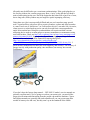
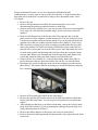
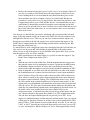
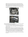
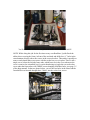
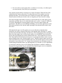
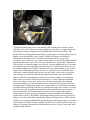
Yamaha Roadliner/Stratoliner
Valve Adjustment & Throttle Body Synchronization
By Ken “the Mucker” Sexton
2/2009
The first thing many people ask me, with regard to doing a valve adjustment on a
Yamaha Roadliner/Stratoliner (or a Road Star!) is… “It’s got hydraulic lifters. So why
does it need to have a valve adjustment?” The answer is: because each hydraulic lifter
operates one pushrod and rocker arm assembly and TWO valves (see the photo below).
Each individual valve and rocker arm finger can be subject to wear at the interfaces
between the rocker arm finger tip & valve stem top and valve head sealing surface and
the valve-seat (in the cylinder head). There is no guarantee that both valves in each pair
will exhibit the same amount of wear at those interfaces. So either valve may, over time,
“sink” into the cylinder head and/or there may be some wear at the bearing surface
between the rocker arm and valve stem top. Of each valve pair, one of them is nonadjustable and the other has a screw & lock-nut adjuster at the end of its rocker arm
finger. If either valve sinks into the head more than its mate or if either rocker arm finger/
valve stem top wears more than the other, the result will be that the two rocker arm
interfaces will no longer maintain constant contact and even pressure. One of them will
develop some clearance between the finger and valve stem top. That can cause an
increase in engine noise if the clearance is sufficient to create an audible impact when the
cam operates those valves and, in worst case scenarios, it can cause accelerated valve,
rocker arm and valve guide wear. Yamaha recommends doing a valve adjustment every
16,000 miles. In my experience, that seems to be a good mileage between valve
adjustments, but I’ve done a few first services on Road Stars that proved to be in need of
a valve adjustment in less than 10,000 miles. Let your conscience (and wallet) be your
guide.
You may wonder why the throttle bodies might need to be synchronized at all. Truth to
tell, if the engine runs smooth at idle and at steady cruise speeds and it’s getting good
mileage, it may not need any adjustment at the throttle bodies. But the two throttle bodies
act like two carburetors on twin-cylinder engines of the recent past and, like carburetors,
those two throttle bodies need to work in unison, delivering the same amount of air and
gas to both cylinders at the same time. The delivery of gasoline is handled by the fuel
injectors and electronics, but the air is metered out by a purely mechanical system.
Balancing the quantity of air into the two cylinders is what synchronization
accomplishes. It has virtually no effect on power production, so you won’t suddenly blast
away from that guy down the road with the “crotch rocket”, but synchronizing the throttle
bodies may improve your gas mileage and how smoothly your ‘Liner runs down the road.
(Don’t whine about the complexity of these new fangled motorsickles. Sure, the Road
Star is easier to work on and, with one carb, doesn’t need anything synchronized. But
sequential fuel injection a big reason why the Roadliner can easily kick the Road Star’s
arse!)
It bears mentioning that throttle body synchronization shares much in common with
doing a compression test. Because they are both a result of or a test of the engine’s
pumping efficiency, they can both be affected by other factors. Synchronization is the
matching of intake pressure (in this case vacuum) between the intake tracts. The ability to
pull a vacuum in the intake system is a direct reflection of the engine’s health and state of
tune. Valve adjustment, spark plug condition, gasoline quality and wear & tear on the
engine itself are all factors in how much vacuum the engine develops and how well the
two intake tracks can be brought into synchronization. If you have neglected the valve
maintenance, don’t be surprised if you find that intake vacuum varies up & down a lot at
idle and it may be difficult to get a consistent synchronization. If the spark plugs have a
lot of miles on them, the vacuum gauges may show a “miss” in the idle that you hadn’t
noticed while sitting on the seat. And if the engine has had a hard life or has a lot of wear,
due to long miles, both cylinders may no longer be equals in pumping efficiency.
Doing these two jobs is not especially difficult and you won’t need too many special
tools. A good tool box with screw drivers, metric wrenches, sockets and Allen wrenches
is a must. And a set of “ball drivers” (or “ball-end hex drivers”) can make life a lot easier,
when access to a socket-head cap screw can only be made from a non-perpendicular
angle. More on that later. Doing the synchronization will require an intake vacuum
measuring devise such as vacuum gauges or mercury manometers or manometers using
steel balls in tubes. Check out http://www.carbtune.com/ or http://www.motionpro.com/
motorcycle/partno/08-0411 for good tools. If you like analog gauges, Emgo Carburetor
Synchronizers can be bought from Dennis Kirk among other places
(http://www.denniskirk.com/jsp/product_catalog/Product.jsp?
skuId=282822&store=Main&catId=&productId=p282821&leafCatId=&mmyId=). I
prefer mercury manometers for their rock-solid simplicity and accuracy. The accuracy of
gauges can vary with production quality, time and abuse, but mercury never needs
recalibration.
If you don’t have the factory shop manual… GET ONE. Yamaha’s service manuals are
generally excellent and, if you’re going to work on your motorcycle, you need all the
proper specifications and instructions from the people who made the machine. Clymer
and Haynes manuals are generally OK (and sometimes all you can get on some older
models of motorcycles and cars), but they aren’t up to the standards of the OEMs.
Keep in mind that this article covers valve adjustment AND throttle body
synchronization, so some steps are not necessary for both jobs. A single asterisk after a
step listed below means that it is particular to doing a valve adjustment on the ‘Liner.
Let’s begin:
• Remove the seat
• Remove the Speedometer Assembly after unscrewing three screws and
disconnecting the multi-pin connectors under its front edge.
• Remove the left side, painted cover- you can just remove the two screws that hold
it on, wrap it in a soft cloth and carefully hang it by the seat-release cable still
attached.
• Remove both chromed covers below the sides of the gas tank- they’re in the
places where air filters might be on other motorcycles. The one on the left covers
a fuel pressure regulator and some hoses and the cover on the right side hides the
ignition coil for the rear cylinder (which Yamaha calls cylinder #1, by the way).
• Make sure there is plenty of gas in the secondary gas tank (under the seat), then
remove the primary Gas Tank- after taking off the rubber plugs on the fuel line
shut-off valves, turn in the screws in the valves, place some rags under the valves
to catch some gasoline and disconnect the fuel hoses from the secondary (under
seat) gas tank. Remove the chromed trim from in front of the tank. Remove the
screws that attach the tank to the frame brackets and lift off the tank.
• Remove the air box assembly. It’s a snug fit between the frame tubes and you
need to disconnect the two drain hoses on the left side for it to clear the frame.
• Disconnect the electrical connector at the top of the secondary gas tank (see the
photo below). This ensures that the fuel pump won’t build fuel pressure when the
key is turned on if you spin the engine over with the starter.*
•
•
•
•
•
Fuel Pump Connector
Remove all four spark plug leads from the spark plugs.*
Remove the ignition coil from the bracket on the right side and then unbolt that
bracket from the main frame. You can wrap it in a rag and let it rest against the
engine.*
After making sure that there is no debris around them, remove the left-side spark
plugs from both cylinders. [If you’re planning on replacing the spark plugs, you
can go ahead and remove all four] *
Remove the rubber dampers on the frame, above the rear rocker-box.*
Remove the bracket that supports the wiring loom above the right side of the front
rocker-box.*
•
Remove the chromed rocker-box covers (“valve covers” to car people). Those of
you who’ve owned pre-2005 Road Stars will notice that the ‘Liners have fewer
screws holding these covers down than the early Road Star three-piece rockerboxes and there are only two lengths of screws to contend with. But the rear
(cylinder #1) rocker-box cover is a snug fit below the main frame and this is why
I suggest that you have a set of ball-end hex drivers. I recommend that you use a
conventional L-shaped allen wrench to loosen the screws and then use the ball
drivers to spin it out (and back in, later). Until the cover can be lifted and moved a
bit to either side of the frame above it, you can’t remove three screws from their
holes in the cover.*
Now that you’ve done all that, you may be wondering why you removed the left spark
plugs. In the shop manual it tells you to remove the shift lever, left side crankcase cover
and right side cam-box cover. That’s so you can use a wrench to turn the engine over,
through an access hole in the left side engine cover, and to position the engine at Top
Dead Center-Compression Stroke while looking at marks on the cam drive gears. But
that’s doing the job the hard way…
It’s much easier to stick a long plastic straw into a spark plug hole (the left side holes are
a bit easier to see & get at) and, while holding it perpendicular to the gasket surface,
allow it to rest on top of the piston so it rises and falls as the piston does. Now you can
turn the engine over by one of two methods:
• Make repeated taps to the starter button very quickly to rotate the engine to Top
Dead Center-Compression Stroke (TDC)
OR
• With the rear wheel raised off the floor, shift the transmission into top gear and
then turn the engine over by turning the rear wheel. I prefer this method because
the Roadliner engine freewheels so easily, that even the briefest touch of the
starter tends to spin the engine too far to accurately orient the crankshaft to TDC.
• Keep in mind that, as you look at the left side (the shift lever side) of the engine,
the crankshaft turns in a counter-clockwise direction. It won’t harm anything to
spin it clockwise, but you’ll notice it takes a bit more effort AND it makes more
noise, which is caused by the starter clutch engaging the starter motor whenever
the engine is spun backwards. Finding TDC-compression stroke is easy. Watch
the valve system in the cylinder head that you’re currently interested in. As the
engine turns over, the pushrods will operate the rocker arms which will open and
close the valves. The valve pairs closest to the throttle bodies are the intakes and
when they are pushed down (opened) that’s the beginning of the intake stroke. As
the intake valves close and the piston rises, that cylinder will be on its
compression stroke, so when the straw has risen to the top of that stroke and just
as it’s about to begin to drop again, that cylinder is on TDC-compression stroke.
This job does not require that the piston be set precisely set to TDC. A few
degrees of crankshaft rotation in either direction will not matter. Now you can use
a feeler gage to check for clearance in all four valves in that cylinder head (TWO
pairs of valves / TWO adjusters in each cylinder head). As a rule, if you can’t get
a .001” or .0015” between any rocker arm finger and its valve stem, you can call
it “zero” and stop there. When in doubt (or if you’re feeling particularly critical),
whichever valve in a valve-pair shows clearance, loosen the lock-nut on the
adjustable finger and back out the adjuster screw until it clears the valve stem.
Then screw it back in with finger-tip effort until it contacts the valve stem again
and then retighten the lock-nut. By doing that, as long as the adjuster doesn’t turn
while tightening the lock-nut, you’re setting both valves on that rocker arm to
zero-lash. Now turn the engine to TDC-compression stroke on the other cylinder
and repeat the valve check/adjustment process.
Front
Rear
If you’re not interested in synchronizing the throttle bodies, you can start the reassembly
procedure now. It is the reverse of disassembly, but…
• Always apply some anti-seize compound on spark plugs before installing them
into the cylinder head. Doing so will insure that the spark plugs don’t seize in the
aluminum threads in the heads. If THAT happens, it can be very difficult and
expensive to repair.
• Because the ‘Liners rocker-box covers are crowded with so much “stuff” above
them, you’ll never have a better time to give them a good cleaning and waxing
than NOW. They are a b*tch to get to when the bike is back in running condition.
Put them on a clean flat surface and make those puppies shine! The chrome will
last longer with a good coat or two of wax on it. As a mechanic who works on a
lot of motorcycles, it’s always a shame to see a rider’s bike pull up looking
“mint”, and then, when it’s on the lift, only to see that the chrome on the rockerboxes is bubbled and peeling where it’s too difficult to access with a casual wash
and waxing.
You’ll never have a better time to polish the rocker box covers than NOW!
NOTE: While doing this job for the first time on my own Roadliner, I pulled back the
rubber sheet covering the frame, in front of the seat latch and drilled two ½” holes in the
cast aluminum, directly above the screws in the rear rocker-box. That makes it possible to
remove and reinstall those two screws with the rocker-box cover in place. There’s still a
single screw, below the left-side frame tube, which has to be in the cover whenever the
cover is removed or reinstalled, but it’s easier than having to juggle the rear rocker-box
cover under the frame tubes with THREE screws dangling from their holes. (see page 3-5
of the shop manual). In the two photos below, you see the two holes in the frame and the
5mm ball drivers inserted through those 2 holes, into the rocker-box screws.
M5 ball drivers, thru frame holes, into cap screws
To synchronize the throttle bodies, reinstall the rocker-box covers, spark plugs and rear
ignition coil. Attach the high voltage leads to the spark plugs, remove the two air pressure
sensors from the ends of the air box and attach them to the 3/16” hoses still attached to
the throttle bodies and reattach the fuel pump connector at the secondary gas tank.
•
•
•
You will need to start the engine without the main gas tank or the air box
installed. I suggest that you use a couple of ½” fuel line connectors and some ½”
ID fuel hose to connect both fuel taps on top of the secondary gas tank to each
other. That’ll keep dirt from falling into the hose stubs and gas from leaking out.
It’s also easier and safer than having them attached to the main gas tank, while it’s
supported on something to the side of the bike. You also need to tap into the
small, plastic braid covered hoses that are connected to the throttle bodies. The
easiest way is to get a couple of 3/16” diameter “T-fittings” at a local auto parts
store (with two 3/16” rubber plugs, which you’ll use later), then cut the hoses
about two inches from the throttle bodies and install the T-fittings between the cut
ends. Now connect two hoses from the vacuum measuring device (mercury
manometers or gauges) to the T-fittings. Note: www.Motionpro.com also sells the
fuel line, T-fittings and lots more great stuff for working on motorcycles.
You don’t need the speedometer assembly attached to the bike to run the engine,
but if you want to monitor engine RPMs, you can wrap some clean rags around
the chrome of the speedometer assembly, leaving the gauges visible. Then attach
the electrical connectors to the wiring harness behind the steering neck and rest it
against the engine and left floorboard.
NOTE: If you are using mercury manometers, you can slowly raise and lower
engine RPMs with the throttle, but DO NOT suddenly chop the throttle closed
after revving up the engine. That can cause a momentarily very-HIGH intake
vacuum which may be strong enough to suck the mercury into the engine. Besides
rendering the manometers useless (until you can get more mercury for the
reservoir), it will result in the expulsion of vaporized mercury from the tail pipe
and you do not want mercury in your lungs. After raising the RPMs, ease the
throttle back to idle position in a controlled manner, while watching intake
vacuum on the manometers.
•
Be sure to have an open garage door, or whatever is necessary, so exhaust gases
are routed outside, away from your environment.
Now start the engine and let it warm up for a couple of minutes. When the fins of the
cylinder head are warm to the touch, it’s ready to be tuned. If you plan to run it for
prolonged periods, you’ll need to have lots of airflow across the entire engine and
exhaust system, but this job shouldn’t take so long that you’ll need exterior cooling.
The actual strength of the intake vacuum isn’t critical and will vary with engine speed,
temperature and load, but you do want both intakes to be within a centimeter difference
in vacuum. Matching the vacuum readings exactly is best for engine balance and
performance. But before we start fiddling with things, let’s leave the ignition key in the
off position and take a look into the intake openings of the throttle bodies and see how
this works…
When the throttle grip is at idle position you can see that the two throttle plates
(butterflies) are almost closing off the bores of the throttle bodies. But there is a small
gap between the throttle plate edges and the bores. That small passage allows enough air
past to feed the engine most of what it needs while it is at idle RPMs. Now look at the
groove that runs straight down into the throttle body bore, with a small hole at its lower
end. That small hole at the bottom of the groove is a passage that allows clean air to get
past the throttle plate to the “throttle bypass screws” and back into the intake tract by way
of the small holes lower still in the throttle body bores. The throttle bypass screws (in the
horizontal recesses below the 3/16” vacuum hose attachments) are the primary means of
synchronizing the throttle bodies. By adjusting them you can make very fine adjustments
to exactly how much air bypasses the throttle plates and then re-combines with the air
that gets directly past them. So you can think of the throttle bypass screws as adjustable
valves for controlled air “leaks” past the throttle plates.
Using the throttle bypass screws, you should be able to make the two intake vacuum
readings exactly even. If the two vacuum readings are more than 1 cm apart, then it may
be necessary to make an adjustment to the linkage between the throttle bodies. The
throttle-shaft runs through both throttle bodies, operating the two throttle plates. It has an
adjuster screw in the middle, with a couple of small coil springs over its threads.
Unfortunately the adjuster screw’s head is on the bottom, where you can’t get a
screwdriver on it, so the only way it can be easily turned is to shut off the engine and then
open the throttle all the way to raise the screw up and make a “guesstimate” adjustment.
Then you have to restart the engine to recheck the vacuum readings and see if you turned
it in right direction and/or the right amount. It may take a couple of tries before you get
the vacuum readings even. While it is possible to use the central adjuster to get a perfect
balance between both throttle bodies (in fact, it is exactly how you would balance the
carburetors on multi-cylinder motorcycles), you may find it easier to use it to get them
close and then to use the individual throttle bypass adjustment screws in the throttle
bodies to make fine adjustments for perfectly even vacuum readings. If you find that
either bypass screw has to be backed out more than 1-1/2 turns to balance the throttle
bodies, re-set them to between ½ and ¾ turns out-from-seated and use the adjusting
screw in the linkage to get a closer balance before going back to the bypass screws for
fine adjustments. Having either bypass screw out more than 1-1/2 turns risks it vibrating
out while motoring down the road. Keep in mind that the engine isn’t sensitive to exactly
how much air it gets straight down the throttle bodies or through the bypass screws, so
long as both intakes are in synchronization. Some riders have reported a smoother
running engine at cruise speeds, by adjusting the vacuum readings while holding the
engine steady at 2000 to 2500 RPMs. The general idea has merit, but as long as the two
bypass screws aren’t adjusted to significantly different settings the two cylinders should
run quite even at higher steady throttle settings. Keep in mind, during engine acceleration
& deceleration, the intake vacuum readings will NOT rise (or fall) in perfect unison, but
when they’re properly adjusted they should stabilize to be very close to each other while
holding a steady throttle.
NOTE: The OEM throttle shaft adjustment screw has a Phillips-screw type head. If it had
a hex head, you’d be able to make adjustments to it with an open-end wrench while the
engine is running. But it is a fine pitch thread, M4-.5 x 12mm screw and the standard M4
thread pitch is .7mm. Finding an M4-.5 hex-head screw is nearly impossible. I was able
to find .5 pitch, 4mm threaded rod and nuts, so I used a bit of the threaded rod and two
M4-.5 nuts to produce a fine pitch M4 screw. With 12mm of exposed thread and the two
nuts jammed together at one end, it’s about 16mm long overall and a 7mm open-end
wrench works well to make vacuum balance adjustments while the engine is running.
You don’t want more than 12mm of exposed thread, because then the coil spring may not
exert enough pressure to keep vibration from causing the screw to back out. If you want
to make your own fine-pitch screw too, check out http://www.mcmaster.com/# and/or do
a search on the web for the 4mm x .5mm threaded rod and nuts.
Custom made M4-.5x12 synchronization adjustment screw (throttle held OPEN)
Once you’ve got the two vacuum readings even, you’re done and all you need to do is to
disconnect the manometer/gauge hoses, use the 3/16” rubber plugs that you bought
earlier to plug the open ports on the T-fittings (which you can leave in place for the next
time you do a service) and reassemble the bike. But if you have any desire to boost your
Roadliner/Stratoliner’s performance, this would be a good time to install a Dynojet
Power Commander fuel injection control module and/or Patrick Racing VBAK
replacement K&N air filters and velocity stacks. (NOTE: you can run a Power
Commander without the PR VBAK, but if you do the inverse, the engine will run too lean
with the better flowing intake and nothing to adjust the fuel injection to compensate for
the increased intake airflow) The OEM airbox is very restrictive AND it has a very small
air filter for such a large displacement engine. Before reinstalling that chocker of an
airbox, now would be a great time to make a change and tidy up the space under the gas
tank while you’re at it. With two K&N air filters in place of the airbox, servicing the
valves and throttle bodies will much easier. In fact, with the PR VBAK installed, I can
now do throttle synchronization by just removing the speedometer assembly and main
gas tank. And only the PCV-hose needs to be removed to access the rear rocker-box
cover. You WILL notice the increased power with the Patrick Racing VBAK & Power
too. IMHO, that’s never a bad thing. The only down side is the cost of the parts and an
increase in intake noise. At idle, the intake for the idle speed control valve makes more
noise than the primary engine intake through the big K&N filters. Some people will be
more bothered by this than others and a noisy exhaust system may mask the noise almost
completely.
(Note: in the photo above, the mounting of the small K&N filter for the idle speed control
valve and both intake pressure sensors are not done according to Patrick Racing’s
instructions).