1
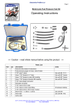
BA-757x-xx
Page: 1
BULLET & MINI-BULLET TACHOMETERS INSTALLATION
GUIDE - Please see appropriate section for your specific
application
Go slowly and follow instructions carefully. The installation is very easy if the
wire color destinations are followed.
Revision: 17.6 - 02/03/2010
Install Time: 30 to 90 Minutes
INCLUDED IN THE KIT:
(1) Chrome Billet Baron Tachometer (Black or White
Face)
(1) Ring Terminal
(3) Blue 3M Scotch-Lock Connectors
(1) 3-wire BA-7315-50 BARON Tachometer Adapter
(1) LED Control Box (only included with 7-color
Tachometer)
(1) Double-Crimp Butt Connectors
(3) Piggy-back Spade Connectors
TOOLS REQUIRED:
5/32" Allen Wrench
Electrician Tape
24" of 20 GA. Wire (Color is irrelevant)
Factory Service Manual
Wire Crimper/Pliers
INSTRUCTIONS:
GENERAL WIRING INSTRUCTIONS:
GREEN WIRE provides the RPM count
BLUE or YELLOW wire provides power for the illumination
RED wire provides power to the Tach
BLACK wire is for ground
INSTALLER NOTES: Reference to LED Control Box is only relevant if you are installing a 7-Color Tachometer, otherwise only worry about the wires
from the Tachometer. To determine if your bikes requires this unit and how to determine the negative side of the coil or to determine if your bike
requires the single fire adapter see FAQ page of this document.
GREEN wire to NEGATIVE terminal of coil.
BLACK wires from Tach and LED Control box both to CHASSIS (Ground)
RED wires from Tach and LED Control box both to POSITIVE terminal of coil (or other switched 12 volt source)
BLUE or YELLOW wire from the Tach go to POSITIVE terminal of coil (or other switched 12 volt source)
7-COLOR TACHOMETERS ONLY
WHITE Connector from Tach to White Connector on LED Control Box
BLACK Switch w/RED button plugs into the LED Control Box WIRING NOTE: If you are equipped to solder your connections we recommend you do
so only after first connecting and testing the tachometer for proper operation.
INSTALLER NOTES: On some models the supplied wiring leads may need to be trimmed to fit the bikes connectors. Use the Ring Terminal for all
chassis ground connections. If you mount your Tach high up on the handlebar, or have tall or pullback risers or wide handlebars, you may need to
splice extra wire to each colored wire lead of your Tachometer prior to completing the routing and connection, then trim to appropriate length.
GENERAL MOUNTING INFORMATION
1. Mount new Baron Tach on handlebar in your preferred position. Ideal location is between handlebar risers. If mounted off-center, you can rotate
Tach face back to vertical (or any position you desire) by first loosening Tach unit's set screw (located in handlebar clamp area of the Bullet housing or
on the underside of the Mini-Bullet housing). Unscrew the housing's bezel (counterclockwise) then rotate the Tach Face to the desired position,
re-tighten the set screw and re-install the bezel.
2. Secure handlebar clamp by first tightening the flat/front dial side of clamp and then the pointed/rear side of clamp until housing does not rotate
under mild pressure. There must be a small gap on the pointed side and no gap on the flat side when the clamp is correctly tightened.
Our install guides provide a basic outline on the proper installation of our products. Further tuning and/or
fitment may be required. Barons bears no responsibility on installation costs associated with this product.
© 2012 Barons Custom Accessories
5221 Oceanus Drive
Huntington Beach, CA 92649
(714)274-4065 - Ph.
(714)901-0520 - Fax
www.baronscustom.com
[email protected]
BA-757x-xx
Page: 2
BULLET & MINI-BULLET TACHOMETERS INSTALLATION
GUIDE - Please see appropriate section for your specific
application
CLAMP GAP NOTE: To prevent fogging be sure to not close the pointed end of the clamp together as this is where the hidden breather vents are
located that provide a constant air exchange.
3. Route Tach's wire harness lead under the dash for simplest and cleanest installation.
1980 to 2003 HARLEY-DAVIDSONS
NOTE: LED Control Box references are only relevant to 7-Color Tachometers. If you have a single color model you will only be concerned with the
wires exiting the Tachometer.
Making your wire connections as follows will not require the use of the Tach Adapter:
GREEN WIRE: Find the PINK wire from the factory wiring harness located under the speedometer (sometimes they have a plastic bullet
shaped end). Cut the plastic off and splice the PINK wire to the GREEN wire from the Tachometer.
BLUE/YELLOW & RED WIRES: Find the ORANGE wire under the dash and attach the Tach power wires BLUE & RED (incandescent) or
YELLOW & RED (single color LED Tachs) to it. On 7-Color LED Tachometers connect RED from the Tach and RED from the LED controller
box.
BLACK WIRE: Locate a suitable ground (usually a bare frame bolt) and attach the BLACK wires from the Tachometer and the LED
controller box (if equipped) using the ring connector.
7-COLOR TACHOMETERS ONLY
WHITE WIRE: White Connector from 7-Color Tach to WHITE Connector on the 7-Color LED Control Box
BLACK SWITCH: w/Red Button plugs into 7-Color LED Control Box
2004 - 2010 HARLEY-DAVIDSONS
ALL MODELS REQUIRE TACH ADAPTER
TACH ADAPTER: The 2004-2010 Harley Davidson will need to utilize the Baron Tach Adapter (BA-7315-50 which is included with your Tach
Kit).
1. Remove the seat & fuel tank per the factory service manual.
2. Remove the plastic wiring harness cover that runs the length of the backbone under the tank.
3. On the left side is the coil harness. Locate the following wires:
YELLOW w/BLUE Tracer, BLUE w/ORANGE Tracer, YELLOW w/GREEN Tracer. These will be used in later steps. NOTE:There are 2
wires you will be using that look VERY SIMILAR. Please pay attention to the ones you connect to, as the Tach will only work if the instructions
below are followed exactly.
WIRE THE TACHOMETER & ADAPTER AS FOLLOWS:
YELLOW WIRE: Use a Scotch-Loc to connect the YELLOW lead from the Tach Adapter to the YELLOW w/BLUE Tracer coil wire.
BLUE WIRE: Use a Scotch-Loc to connect the BLUE lead from the Tach Adapter to the BLUE w/ORANGE tracer coil wire.
GREEN WIRE: Connect the GREEN wire from the Tach adapter to the GREEN wire from the Tachometer with the included Red butt
connector. The GREEN wires ONLY connect to one another; DO NOT CONNECT them to any positive power source or you will burn the unit
out.
BLUE/YELLOW & RED WIRES: Find switched power from the bike (you can use the ORANGE wire from the bikes harness or the
YELLOW w/GREEN Tracer wire). Use a Scotch-Loc to connect either the BLUE & RED wires (incandescent Tach model), or the YELLOW &
RED wires (single-color LED Tach model) and splice them to the YELLOW w/GREEN Tracer wire on your harness. For 7-color LED Tachs,
use the RED wire from the Tach and the RED wire from the LED controller box and splice them to the YELLOW w/GREEN Tracer wire on
your harness.
BLACK WIRE: Attach BLACK wire from the Tachometer and LED Control Box on 7-Color Tachometers to a suitable ground (usually a bare
frame bolt). Use the Ring terminal (supplied).
7-COLOR TACHOMETERS ONLY
WHITE WIRE: White Connector from 7-Color Tach to WHITE Connector on the 7-Color LED Control Box
BLACK SWITCH: w/Red Button plugs into 7-Color LED Control Box
Our install guides provide a basic outline on the proper installation of our products. Further tuning and/or
fitment may be required. Barons bears no responsibility on installation costs associated with this product.
© 2012 Barons Custom Accessories
5221 Oceanus Drive
Huntington Beach, CA 92649
(714)274-4065 - Ph.
(714)901-0520 - Fax
www.baronscustom.com
[email protected]
BA-757x-xx
Page: 3
BULLET & MINI-BULLET TACHOMETERS INSTALLATION
GUIDE - Please see appropriate section for your specific
application
UNIVERSAL TACHOMETER INSTRUCTIONS FOR METRIC & BRANDS OTHER THAN
HARLEY-DAVIDSON
These instructions cover installing this Tach on most Metric and Non Harley motorcycles. Some vehicles may require the included Tach
adapter. Please see FAQ on the final page of the instructions for information on how to determine whether your bike requires the Tach Adapter.
Wiring instructions are included separately for the adapter.
Tools required:
2.5, 4 & 5MM Allen Wrenches
10 & 12 MM Sockets
10MM Open-end wrench
Pliers (Std. & Needle Nose)
Electrical Tape / Shrink Tube
Factory Service Manual
INSTALLER NOTES: Reference to LED Control Box is only relevant if you are installing a 7-Color Tachometer, otherwise only worry
about the wires from the Tachometer. To determine if your bikes requires the BA-7515-50 Tach Adapter and how to locate the negative
side of the coil see FAQ page of this document.
WIRING INSTRUCTIONS:
Wire Baron's Tach to one of your motorcycles ignition coils via the following method:
GREEN WIRE from Tach to NEGATIVE terminal of coil (or direct to Green from the Tach Adapter if your bike requires the single fire
adapter.
BLACK WIRE from Tach and the LED Control box on 7-Color Tachometer both go to CHASSIS (Ground)
RED WIRE from Tach and LED Control box on 7-Color Tachometer both go to POSITIVE terminal of coil (or other switched 12 volt
source)
7-COLOR TACHOMETERS ONLY
WHITE Connector from 7-Color Tach to WHITE Connector on the 7-Color LED Control Box
BLACK SWITCH box w/Red Button plugs into 7-Color LED Control Box
FREQUENTLY ASKED QUESTIONS (FAQ):
We appreciate your business and hope you have had a successful installation. Should you be experiencing any oddities, or have questions
we would appreciate you taking a moment to review the information below. You will find answers to the most common questions and
explanations that will in most cases take care of your needs. If after reviewing the information and you are still having issues , please
contact us by email at [email protected] or on our TECH phone at 714-274-4098.
TACH ADAPTER
Q: How do I know if I need the Tach Adapter (BA-7315-50)
A. In most cases if your bike has a fuel-injected or single-fire ignition you will need the Tach Adapter.
Q. I installed the Tach and it seems to be registering half the RPM's, whats wrong?
A. You most likely need the Adapter.
TACH ADAPTER KNOWN FITMENT
We have tested this adapter and determined:
IT IS REQUIRED ON All HARLEY DAVIDSON Models 2004-2010, YAMAHA V-Star 950 & 1300, 2008-2009 Road Star, Warrior,
Roadliner, Stratoliner, Raider, HONDA VTX1800 , KAWASAKI VN900 & VN2000, SUZUKI C50 & C90
IT IS NOT REQUIRED ON: HARLEY DAVIDSON models using the stock Tach output from the bike (PINK wire), YAMAHA Road
Star, Royal Star, RSTD, Venture or 1998 to 2010 Vstar 650 & 1100, KAWASAKI VN1500/VN1600 Models, HONDA VTX1300
ELECTRONIC FUEL INJECTION (EFI)
This adapter may or may not be required on fuel-injected 2 or 4-cylinder bikes not listed above. If you have installed the Tach and it is
registering half the RPM's needed you would most likely need the Tach Adapter.
BULB REPLACEMENT
Q: How do I replace the light bulb in my Tach?
A: Remove Tach from the handlebars. In the handlebar clamp area of the Tach housing there is a set screw: Loosen it, remove the Tach
housing bezel by unscrewing (counterclockwise) from the housing, slide the Tach instrument out of the housing. On the rear of the
Stainless Steel Tach unit there is a rubber plug: Remove the plug. The bulb is in a bayonet style holder just under the plug. Rotate holder
1/4 turn to remove, and pull the bulb out.
Our install guides provide a basic outline on the proper installation of our products. Further tuning and/or
fitment may be required. Barons bears no responsibility on installation costs associated with this product.
© 2012 Barons Custom Accessories
5221 Oceanus Drive
Huntington Beach, CA 92649
(714)274-4065 - Ph.
(714)901-0520 - Fax
www.baronscustom.com
[email protected]
BA-757x-xx
Page: 4
BULLET & MINI-BULLET TACHOMETERS INSTALLATION
GUIDE - Please see appropriate section for your specific
application
REPLACEMENT BULB - .10A 14V T-1 3/4 WEDGE, #18 MINIATURE BULB GLASS WEDGE BASE like a Sylvania 74 or equivalent
GE74.BP221029 style which are available at most auto parts stores or online light bulb suppliers.
LED ILLUMINATION
7-color LED or Single Color LED Tachometers do not have replaceable light sources. However, LEDs typically last a very long time so
it is unlikely you will have an issue.
NEEDLE BOUNCING
Q: My Tach is bouncing at idle, what does this mean?
A1: Typically, needle bounce is caused by low idle when idle is set under 1000 RPM's. Adjusting the idle upwards between 1000 to 1200
RPM usually smooths out the needle. If you choose to keep it lower, you may experience some bouncing at idle. This does not negatively
affect Tach operation.
A2: It is also possible you have a poor connections on the RED, GREEN or BLACK wires. We recommend you check and possible solder
all connections to assure solid connections.
FOGGING
Q: My Tach face has fogged up, what do I do?
A: Tach fogging can occur when the outside air temp is warmer than the inside of the Tach, and humidity is high. Baron Tachs feature
hidden vent holes in the Tach body, these are located next to the wire exit point on the pointed end of the bar-clamp. It is important the
clamp be tightened so the holes are not closed off at the pointed/rear side of the clamp and so an open air exchange can occur. This means
the flat edge of the clamp that faces the rider should be tightened down until it lightly touches and the forward facing pointed end of the
clamp has a gap for the vents to work properly.
UNDER THE HANDLEBAR MOUNTING
A: Can the Tach be mounted inverted under the handlebars?
A: Yes, if you have enough room to mount under the handlebars for the tach to mount and still be able to turn from lock to lock without
hitting the tank or dash. See note in next paragraph for details on how to rotate the face of the Tach for appropriate positioning. BE
AWARE: Chances of water intrusion are increased in this position!
FACE ROTATION
Q: How do I rotate the face of the Tach?
A: With the Tach housing removed from the handlebar, unscrew the bezel (counterclockwise) and remove it from the housing, using a
5/32 Allen wrench loosen the the set-screw located inside the clamp area or at the rear of the clamp area. Rotate the face of the Tach to
your preferred position, tighten the set screw and replace the bezel.
COIL IDENTIFICATION
Q: How can I tell positive from negative on my coil?
A: Most motorcycles will have two wires going to each of the coils, and each coil will share one common-color wire and have one unique
color wire. The common-color is the positive and the unique color is the negative. For example, a Yamaha set-up has a red/black on both
coils - that is positive. The other coil wire would be orange or gray - that is the negative side. Hondas set-up is blue/yellow and
yellow/blue for the negative, and black/white for the positive. Suzuki has orange/white on both coils as positive and has white or
black/yellow as the negative side.
COIL SELECION
Q: My bike has two (or four) coils - Which one/ones do I use?
A: Most multi-cylinder bikes have one coil per cylinder. You only need to connect to one of the coils - choose the one most convenient for
wire routing. (Single-fire motorcycles require the Tach adapter we include with each assemble.
Our install guides provide a basic outline on the proper installation of our products. Further tuning and/or
fitment may be required. Barons bears no responsibility on installation costs associated with this product.
© 2012 Barons Custom Accessories
5221 Oceanus Drive
Huntington Beach, CA 92649
(714)274-4065 - Ph.
(714)901-0520 - Fax
www.baronscustom.com
[email protected]
BA-7315-50
TACHOMETER ADAPTER (Single Fire)
Page: 5
CAUTION! We Strongly recommend that a qualified technician install this kit
if you do not completely understand the instructions prior to the install.
Revision: 3.9 - 02/03/2010
INCLUDED IN THE KIT:
(1) Baron 3-wire Tach Adapter
(3) Spade Connectors
(3) Piggy-back Connectors
(1) Butt Connector
(3) Scotch-Loc Connectors
(1) Ring Terminal
TOOLS REQUIRED:
Crimp tool (or std. pliers)
Electricians Tape
Needle-nose Pliers
Factory Service Manual
Wire Strippers
INSTRUCTIONS:
Note: This part may also work with other manufactures tachometers, although we cannot guarantee its
functionality unless it is used with a Baron Tach.
TACH ADAPTER KNOWN FITMENT
We have tested this adapter and determined:
IT IS REQUIRED ON All 2004 - 2010 HARLEY DAVIDSON models, YAMAHA V-Star 950 & 1300,
2008-2010 Road Star, Warrior, Roadliner, Stratoliner, Raider, HONDA VTX1800 , KAWASAKI VN900 &
VN2000, SUZUKI C50 & C90
Our install guides provide a basic outline on the proper installation of our products. Further tuning and/or
fitment may be required. Barons bears no responsibility on installation costs associated with this product.
© 2012 Barons Custom Accessories
5221 Oceanus Drive
Huntington Beach, CA 92649
(714)274-4065 - Ph.
(714)901-0520 - Fax
www.baronscustom.com
[email protected]
BA-7315-50
TACHOMETER ADAPTER (Single Fire)
Page: 6
IT IS NOT REQUIRED ON 1980-2003 HARLEY DAVIDSON models using the stock Tach output from the
bike (PINK wire), YAMAHA Road Star, Royal Star, RSTD, Venture or 1998 to 2010 Vstar 650 & 1100,
KAWASAKI VN1500/VN1600 Models, HONDA VTX1300
Make connections as follows:
YELLOW wire of adapter to NEGATIVE on front coil (use the spade connector and the piggyback on your
stock coil)
BLUE wire of adapter to NEGATIVE on rear coil (use the spade connector and the piggyback on your stock
coil)
GREEN wire of adapter to green wire of tach (input) (Use the butt connector)
The GREEN wires ONLY connect to one another; DO NOT CONNECT them to any positive power source or
you will burn the unit out.
RED and BLUE or YELLOW wires of Tach to POSITIVE terminal of coil (or other switched 12-volt source)
BLACK wire of tach to CHASSIS (ground)
To determine POSITIVE and NEGATIVE of your coils: Most motorcycles will have two wires going to each of
the two coils. Each coil will share one common color wire and will have one different color wire. The common
color is positive, and the different colors are negative. For example: Yamaha has a red/black wire on both coils
- that is positive. The other wire is orange or gray - that is the negative side. Honda is black/white for positive,
and blue/yellow and yellow/blue for negative. Suzuki has orange/white on both coils as positive, and white or
black/yellow as negative. Kawasaki has red/green for common positive, and black or black/green for the
negative side. Harley Davidson has yellow/green for common positive and the negatives are blue/orange for the
front cylinder, and yellow/blue for the rear cylinder.
Our install guides provide a basic outline on the proper installation of our products. Further tuning and/or
fitment may be required. Barons bears no responsibility on installation costs associated with this product.
© 2012 Barons Custom Accessories
5221 Oceanus Drive
Huntington Beach, CA 92649
(714)274-4065 - Ph.
(714)901-0520 - Fax
www.baronscustom.com
[email protected]