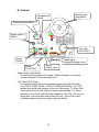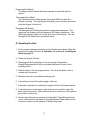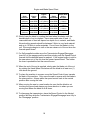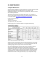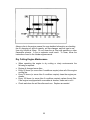
1
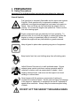
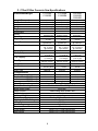
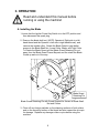
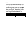
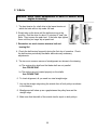
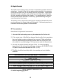
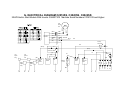
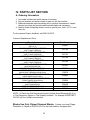
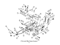
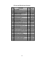
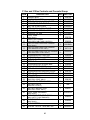
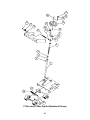
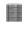
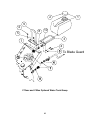
OWNERS MANUAL MEDIUM CONCRETE SAWS C1316SS C1320SS MODELS: C1316SM C1320SM C2016SS C2020SS C2024SS FORM C2020SS rev 5-11 WARRANTY Norton warrants all products manufactured by it against defects in workmanship or materials for a period of one (1) year from the date of shipment to the customer. The responsibility of Norton under this warranty is limited to replacement or repair of defective parts at Norton's Stephenville, Texas facility, or at a point designated by it, of such part as shall appear to us upon inspection at such point, to have been defective in material or workmanship, with expense for transportation borne by the customer. In no event shall Norton be liable for consequential or incidental damages arising out of the failure of any product to operate properly. Integral units such as gasoline engines, electric motors, batteries, tires, transmissions, etc., are excluded from this warranty and are subject to the prime manufacturer's warranty. This warranty is in lieu of all other warranties, expressed or implied, and all such other warranties are hereby disclaimed. Important: Before placing equipment in operation, record the following information. MODEL:_________ SERIAL NO.___________ PURCHASE FROM: _____________________ ADDRESS: ____________________________ CITY_______ STATE ______ ZIP ________ TELEPHONE NO. ______________________ Before using this equipment, make sure that person using it read and understand the instructions in this owners manual. 2 Table of Contents CONTENTS I. Preparation A. Safety Precautions B. Assembly C. Concrete Saw Specifications II. Operation A. Blade Installation B. Changing the Blade Side C. Starting The Engine D. Water Supply E. Controls F. Operating The Saw G. Cutting Technique H. Lead-Off Adjustment III. Maintenance A. Engine Engine Warranty B. Bearings C. V-Belts D. Depth Control E. Transmission F. Self-Propelling Unit G. Electrical Diagram 13HP Manual Start Electrical Diagram 13HP Electric Start Electrical Diagram 20HP Electric Start PAGE 4-6 7 8 9-11 12-1414 14-15 15-17 17-19 19-20 20 21-22 23 24 25 26 26 27-28 29 30 31 GX620TXF2 Machine Serial Numbers 07051033 and Higher IV. Parts List Section A. Ordering Information Common Replacement Parts B. Assembly Drawings/Service Parts Listing Frame Common Group Raise Axle Group Transmission Group Blade Shaft and Engine Group Blade Guard Group Controls and Console Group Depth Adjustment Group Optional Water Tank Group 33 33 34-49 34-35 36-37 38-40 41-42 43-44 45-46 47-48 49-50 Read Owners Manual Before Use Safety Alert Symbol: Information Following This Symbol Is Very Important. 3 I. PREPARATION A. Safety Precautions Important! The following safety precautions must always be observed. Hazard Symbols Fuel (gasoline) is extremely flammable and its vapors can explode if ignited. Store gasoline only in approved containers, in well ventilated, unoccupied areas approved, and away from sparks or flames. Don not fill the saw fuel tank while the engine is hot or running. Do not start the engine near spilled fuel. Never use the fuel as a cleaning agent Engine components can get extremely hot from operation. To prevent burns, do not touch the engine or related parts while the engine is running or immediately after it is turned off. Never operate the engine with any heat shields or guards removed. Keep all guard in place when operating any piece of equipment Keep hands, feet, hair, and clothing away from all rotating parts Lethal Exhaust Gas use only in well ventilated areas. Engine exhaust gases contain poisonous carbon monoxide which is orderless, colorless, and can cause death if inhaled. Avoid inhaling exhaust fumes, and never run the engine in a closed building or confined area Never tamper with the governor components of settings to increase the maximum speed. Severe personal injury and damage to the engine or equipment or equipment can result if operated at speed above maximum. Always obey the maximum speed rating of blade. DO NOT LIFT THE SAW BY THE HANDLE BARS 4 Dust and Silica Warning Grinding/cutting/drilling of masonry, concrete, metal and other materials can generate dust, mists and fumes containing chemicals known to cause serious or fatal injury or illness, such as respiratory disease, cancer, birth defects or other reproductive harm. If you are unfamiliar with the risks associated with the particular process and/or material being cut or the composition of the tool being used, review the material safety data sheet and/or consult your employer, the material manufacturer/supplier, governmental agencies such as OSHA and NIOSH and other sources on hazardous materials and make certain to comply with all product warnings and instructions for the safe and effective use of the material being cut. California and some other authorities, for instance, have published lists of substances known to cause cancer, reproductive toxicity, or other harmful effects. Control dust, mist and fumes at the source where possible. In this regard use good work practices and follow the recommendations of the manufacturer/supplier, OSHA/NIOSH, and occupational and trade associations. Water should be used for dust suppression when wet cutting is feasible. When the hazards from inhalation of dust, mists and fumes cannot be eliminated through engineering controls such as vacuum and/or water mist, the operator and any bystanders should always wear a respirator approved by NIOSH/MSHA for the material being cut. Use Approved: Eye Protection Hearing Protection Respiratory Protection 5 Head Protection 1. Before mounting any blade on the saw, the blade should be inspected for any damage which might have occurred during shipment, handling or previous use. 2. The blade collars and arbors should be cleaned and examined for damage before mounting the blade. 3. The blade must be properly fitted over the arbor with the drive pin on the outside collar projecting through the drive pin hole on the blade and inside collar. 4. The blade shaft nut, which is a left hand thread nut, must be tightened securely against the outside blade shaft collar. 5. The blade must be operated within the specified maximum operating speed listed on the blade. 6. Turn water control valve to full to provide adequate coolant (5 to 8 gallons per minute) for diamond blades and wet cutting abrasive blades. Insufficient coolant could result in severe blade breakage or diamond segment separation. 7. The blade guard must be in place with the nose guard down and locked when the saw is running. 8. The operator should wear safety glasses and any other appropriate safety equipment. 9. When starting the saw, the operator should stand away and to the side of the blade. 10. If for any reason the saw should stall in the cut, raise the blade out of the cut. Check the outside blade shaft collar and nut for tightness. Inspect the blade for damage before restarting the saw. User caution when resuming a cut. Be certain that the blade is in alignment with the previous cut. 11. During cutting operations, do not exert excess side pressure on the handles as a method of steering. Do not force the blade into the cut by lowering the blade too fast or by pushing the saw too fast. You Are Responsible For Your Safety!!! 6 I. PREPARATION B. Assembly The self-propelled concrete saws are shipped completely assembled and ready for use except for diamond blade, gasoline, oil, and handle bar. Inspect the saw for shipping damage. If any damage is found, contact the shipper immediately and file a freight claim. The Norton Company is not responsible for any freight-related damages. Remove the saw from the pallet. Reverse the position of the handlebars so that the handle bar sticks out towards the operator. Adjust the handlebars to the desired height. Attach the handlebars to the saw with the supplied hardware. For electric start models fill and check the electrolyte level and charge the battery. Read and understand the remaining sections of this Owners Manual. NOTE: Do not install the blade until it is time to use the saw. ANSI regulations prohibit the transportation of any concrete saw with the blade installed. 7 C. C13xx/C20xx Concrete Saw Specifications Dimensions/Weight Length (Transport) Width Height Weights Engine Engine Mfg. Model Spec No. Engine Type Horse Power Max Torque Cooling System Oil Capacity Fuel Capacity Fuel Type Low Oil Sensor Air Filtration Start Type Characteristics Max Blade Depth of Cut 24” (406 mm) 20” (356 mm) 16” (305 mm) Arbor Bore Blade Shaft Locking Device Blade Shaft Speed Depth Control Depth Lock Number Of V-Belts Blade Guard Type Right or Left Side Cutting Lifting Bale Handle Bars Recessed Rear Wheels Front Wheel Rear Wheel C1316SS C1320SS C1316SM C1320SM C2016SS C2020SS C2024SS 56 inch (1142 mm) 56 inch (1142 mm) 56 inch (1142 mm) 26 inch (660 mm) 26 inch (600 mm) 26 inch (600 mm) 40 inch (1016 mm) 40 inch (1016 mm) 40 inch (1016 mm) 385 lbs (175 kg) 405 lbs (175 kg) 428 lbs (195 kg) Honda Honda Honda GX390 GX390 GX620 GX390K1QXC9 GX390UT1QAE2 GX620TXF2* Single Cylinder 4 Cycle 13 hp (9.5kW) @ 3,600 rpm 19.5 ft-lbs (26.5 Nm, 2.7 kgf-m) @ 2,500 rpm Air Single Cylinder 4 Cycle 13 hp (9.5kW) @ 3,600 rpm 19.5 ft-lbs (26.5 Nm, 2.7 kgf-m) @ 2,500 rpm Air 1.1 liter (1.16 US qt) 6.5 liter (1.79 US gal) Unleaded Gasoline (86 pump octane) Yes 1.1 liter (1.16 US qt) 6.5 liter (1.79 US gal) Unleaded Gasoline (86 pump octane) Yes Four Stage Honda Cyclone Two Stage Honda Two Cylinders 4 Cycle 20 hp (14.9kW) @ 3,600 rpm 32.5 ft-lbs (44.13 Nm, 4.50 kgf-m) @ 2,500 rpm Air 1.8 liter (1.90 US qt) 8.03 liter (2.12 us gal) Unleaded Gasoline (86 pump octane) Yes Four Stage Honda Manual Electric Electric 20” (356 mm) 20” (356 mm) 24” (406 mm) -NA- -NA- 9-1/2 inch (241 mm) 7-1/2 inch (191 mm) 7-1/2 inch (191 mm) 7-1/2 inch (191 mm) 5.50” (140 mm) 5.50” (140 mm) 5.50” (140 mm) 1 inch (25.4 mm) Machined Into Flats Of Tight Collar 2600 rpm, Hand Wheel With Screw Feed Standard 4 Pivoting All Steel Construction Standard Built In Adjustable Standard Wheel 5 x 2 x ¾ With Roller Bearing Wheel 6 x 2 x ¾ With Roller Bearing 8 II. OPERATION Read and understand this manual before running or using the machine! A. Installing the Blade 1. Insure that the Ignition Power Key Switch is in the OFF position and then disconnect the spark plug. 2. Remove the blade shaft nut, (NOTE: Operator’s Right side is a left hand thread and the Operator’s Left side is right hand thread), and remove the outside collar. Rotate the Blade Guard to gain better access to the Blade Shaft Nut, Loose Collar, Blade, and Tight Collar. To Rotate the Blade Guard pull the Blade Guard Retaining Pin out away from the Blade Guard Frame Bayonet and the rotate the Blade Guard up and out of the way. Blade Guard Retaining Pin Blade Guard Retaining Pin with Guard Rotated for Access to Blade Shaft Nut and Collars 3. Clean off any foreign particles on the clamping surfaces of both collars and on the mounting surface of the blade and also inspect the drive pin for damage. Replace any damage collars or pins before using the machine. 9 4. Inspect the blade for any damage, cracks, burnt or blue areas, missing segments, and roundness of blade. Also inspect the arbor hole and drive pin hole to insure both are round. If any problems are found do not use the blade. In addition check that the blade is the correct specification for the application. Use only Clipper Diamond Blades. This machine was not designed for the use with abrasive blades. 5. Place the blade on the blade shaft, lining up the drive pin hole in the blade with the drive pinhole in the inside collar. NOTE: Diamond blades are direction dependent so verify the direction of rotation of the blade. The machine will rotate the blade into the work surface (down cut). Place the blade guard in position and insert the blade guard retainer pin. Never operate the saw without the blade guard or blade guard retainer pin in position See the following diagram Blade Installation. Blade Guard Drive Pin Hole Drive Pin Inside Collar Outside Collar Directional Arrow Blade Installed NOTE: Blade Guard is shown open for clarity. Do not operate with the Blade Guard Open. Blade Blade Shaft Nut Arbor Hole Blade Installation 6. Slide the outside blade shaft collar onto the blade shaft. The drive pin on the outside collar must project through the drive pin hole in the blade and into the inside collar. 7. Tighten the blade shaft nut (counter-clockwise for the Operator’s Right Hand side and clockwise for the Operator’s Left hand side). 10 8. Insure that the Blade Guard is lowered and the Blade Guard Locking pin is secure. Close Blade Guard Nose. See Blade Installed diagram below. Blade Installed 9. Reconnect the spark plug. Observe rotation arrow on blade and do not exceed maximum RPM stamped on blade. NOTE: Organic bonded blades (A) must have a blotter. The blotter (B) must extend past the blade collar contact area as shown. Blades Use Only Norton Clipper Diamond Blades 11 B. Changing the Blade Side: 1. Insure that the Ignition Power Key Switch is in the OFF position and then disconnect the spark plug. 2. Remove the blade shaft nut, (NOTE: Operator’s Right side is a left hand thread and the Operator’s Left side is right hand thread), and remove the outside collar. 3. Clean off any foreign particles on the clamping surfaces of both the outside and inside collars and on the mounting surface of the blade and inspect the both collars for any damage and also inspect the drive pin for damage. Reinstall the Blade Shaft Collars to the machine. NOTE: Replace any damage collars or pins before using the machine. 4. Inspect the blade for any damage, cracks, burnt or blue areas, missing segments, and roundness of blade. Also inspect the arbor hole and drive pin hole to insure both are round. If any problems are found do not use the blade. In addition check that the blade is the correct specification for the application. 5. Remove the Blade Guard from the machine by unscrewing the Blade Guard Pivot Bolt from the rear of the Blade Guard. NOTE: Keep the ½” Flat Washer and ½” Lock Washer on the Bolt. ½” Flat Washer ½” Lock Washer Blade Guard Pivot Bolt Blade Pivot Bolt Removal 6. Remove the Blade Shaft Guard by removing the Blade Shaft Guard retaining bolts. See Blade Shaft Guard Removal diagram below. 12 Blade Shaft Guard Blade Shaft Guard Removal 7. Place the blade on the blade shaft, lining up the drive pin hole in the blade with the drive pinhole in the inside collar. NOTE: Diamond blades are direction dependent so verify the direction of rotation of the blade. The machine will rotate the blade into the work surface (down cut). 7. Slide the outside blade shaft collar onto the blade shaft. The drive pin on the outside collar must project through the drive pin hole in the blade and into the inside collar. 8. Tighten the blade shaft nut (counter-clockwise for the Operator’s Right Hand side and clockwise for the Operator’s Left hand side). 9. Place the blade guard in position and insert and tighten the Blade Guard Pivot Bolt. Never operate the saw without the blade guard or blade guard retainer pin in position See the diagram Blade Shaft Installation on page 10 and Blade Installed on page 11. 10. Insure that the Blade Guard is lowered and the Blade Guard Locking pin is secure. Close Blade Guard Nose. 11. Attach the Blade Shaft Guard to the opposite side of the machine. 12. Remove the Pointer and reattach it to the Operators Left hand side of the machine. NOTE: Reverse the orientation of the Pointer 13. Reconnect the spark plug. 13 C. Engine Operation Prior to attempting to operate the engine, read the information contained in the engine owner's manual. An engine owner’s manual is supplied with every gasoline powered concrete saw. 1. Check Oil: Add oil if low. Refer to the engine owner's manual for the recommended SAE viscosity grades. Capacity of oil is 1.1 liters (1.16 US qt) 2. Check Fuel: Fill if low. Use only unleaded gasoline with a pump sticker octane rating of 86 or higher is recommended. Never use an oil and gasoline mixture! 3. Air Cleaner: Never run the engine without the air cleaner! Rapid engine wear will result from contaminants being drawn through the carburetor and into the engine. 4. Engine Starting: Refer to the engine owner's manual for proper engine starting procedure. 5. Engine Speed: Always run the engine and the proper speed for the blade being used. Never run the blade at a higher speed that it is rated for. See the Blade Speed chart located on the machine’s console or located in the manual under the heading “Operating the Saw” D. Water Supply Pressurized source: Turn the water control to full "ON" when using wet cutting blades. The required flow rate is 4-6 gallons per minute. Optional Water Tank on saw: This supply is designed for use with dry blades to keep the dust levels down. The tank will not supply the proper water flow rates when used with wet cut only blades. Do not drink the water from this tank. Fill the tank with water only. Close the water tank valve. Attach the saws water supply hose to the tank outlet. Fill the tank with water. The capacity of the tank is 5 US Gallons. When you are ready to cut, adjust the water supply rate until a fine mist or a slow trickle is made. The use of water greatly decreases the amount of dust produced during the cutting process, aids in the cooling of the blade, and provides additional stability. Use Only Water In The Water Tank Do Not Drink From The Tank 14 E. Controls Depth Control Hand Wheel Emergency Kill Switch Tachometer/Hour Meter Raise Levantar Engine Ignition Switch Blade Speed Chart Tabla de Velocidad Del Disco 3600 RPM Lower Bajar RPM/Hours (RPM/Horas) Blade Shaft Pulley Dia Eng Pulley Blade Shaft Blade Dia Eng rpm Diámetro en Diameter RPM Diametro de Flecha Disco Polea de Motor rpm Diámetro en Disco RPM Flecha Disco Polea Motor 16" (406mm) 3,600 rpm 3.15" (80mm) 2,520 rpm 4.5" (114mm) 16" (406mm) 3,600 rpm 3.15" (80mm) Ignition Ignicion Emergency Stop Paro de Emergencia 2,520 rpm 4.5" (114mm) 20" (508mm) 3,600 rpm 3.15" (80mm) 2,520 rpm 4.5" (114mm) 24" (609mm) 3,600 rpm 2.65" (67mm) 2,120 rpm 4.5" (114mm) Foward Adelante Throttle Acelerador Transmission Transmisión Fuel Tank 20 HP ONLY Reverse Reversa Engine Throttle Transmission Engage/Disengage Lever Choke 20 HP ONLY Speed Control Lever Depth Control Hand Wheel: Controls the cutting depth of the blade. Rotate Clockwise to raise and counter clockwise to lower the depth of cut. Fuel Tank (20 HP Only): An internal all metal fuel tank is standard equipment for 20 HP models only (C2016, C2020, C2024, PC2016, PC2020,and PC2024). All 13 HP models have a fuel tank attached to the top of the engine. To fill the Fuel Tank remove the Fuel Cap slowly, fill tank to approximately 1-½” below the bottom of the Fuel Tank Neck and reattach the Fuel Cap. Do not over fill the tank. Avoid fuel spills and contact with fuel. Only re-fuel in well ventilated areas and way from sparks and open flames. 15 Transmission Engage/Disengage Lever: Controls the Engagement and Disengagement of the Transmission. Push down to Engage and pull up to disengage the transmission. Only operate the Transmission Engage/Disengage Lever when the machine is NOT moving. Operation of the Transmission Engage/Disengage Lever while the machine is moving may damage the Rear Wheels. When the Transmission Engage/Disengage Lever is in the Disengage position the machine can be moved with out the engine running. NOTE: When parking the saw, it should always be left in the Engaged position, Speed Control Lever in the neutral position, the engine OFF, and perpendicular (right angle) to the grade (hill). Speed Control Lever: Controls the forward and reverse speed of the Transmission. To increase the forward speed push the lever forward with the engine running at full speed and the Transmission engaged. To reverse move the Speed Control Lever towards the rear of the machine. NOTE: The further forward or reverse the Speed Control Lever is moved the faster the machine will move in this direction. To place in a neutral speed condition place the Speed Control Lever in the center. NOTE: Over time the neutral position may change slightly due to cable stretch and mechanical component wear. Either re-adjust the Transmission Control Cable Linkage or move the Transmission Speed Control Lever to it’s new position. Choke 20 HP ONLY: Units with a 20 HP Engine (C2016SS, C2020SS, and C2024SS) are equipped with a remote mounted Engine Choke Control. To operate the Choke pull the control lever out away from the machine and then follow the instructions for starting the engine found in the Engine manual. All 13 HP units are equipped with a Choke control attached to the Engine below the Air Cleaner on the Operator’s Right Hand Side. Engine Throttle: The Engine Throttle Control allows the operator to adjust the Engine Speed while starting and operating the machine. To increase the Engine Speed push the Engine Throttle Control forward. To decrease the Engine Speed pull the Engine Throttle Control to the rear. 16 Engine Ignition Switch: The Engine Ignition Switch allows the operator to start and stop the engine. Tachometer/Hour Meter: The Tachometer/Hour Meter shows the engine RPM only when the Engine is running. The total Engine operating hours (run time) are shown when the Engine is turned off. Emergency Kill Switch: The Emergency Kill Switch will stop the engine when depressed. The engine will not restart until the Emergency Kill Switch is pulled out. Use the Engine Ignition Switch for normal shut down of the Engine. Use the Emergency Kill Switch when a problem arises. E. Operating the Saw 1. For the engine starting instructions see the Engine manual and follow the instructions located in section II. Operation sub heading A. Installing the Blade on page 10. 2. Check the Engine Oil level. 3. Disengage the Self-propelling unit by moving the Transmission Engage/Disengage lever fully up and place the Speed Control in the neutral position. 4. Raise the saw to the full upright position. Do not let the blade come in contact with the ground. 5. Maneuver the saw to the desired starting point. 6. If wet cutting connect the water supply to the saw. 7. Follow the instructions for starting the engine found in the Engine manual. 8. If wet cutting turn on the water supply at the source and then open the water valves on the saw. Make sure that there is a minimum of two gallons per minute of water flow!! 9. Be sure that the engine is running at full throttle!!! Check Engine Speed on the Tachometer to that listed on the Blade Speed Chart located on the Console is correct for the diameter of Blade being used. 17 Engine and Blade Speed Chart Blade Diameter 14" (356mm) 16" (406mm) 20" (508mm) 24" (609mm) Engine RPM Engine Pulley Diameter Blade Shaft RPM 3600 RPM 3.15" (80mm) 2520 RPM 3600 RPM 3.15" (80mm) 2520 RPM 3600 RPM 3.15" (80mm) 2520 RPM 3600 RPM 2.65" (67mm) 2120 RPM Blade Shaft Pulley Diameter 4.5" (114mm) 4.5" (114mm) 4.5" (114mm) 4.5" (114mm) 10. Slowly lower the blade by rotating the hand wheel clockwise until the desired depth of cut is reached. Use a reasonable rate of feed. A reasonable rate of feed will depend on depth of cut, material, and blade. Normal cutting speeds should be between 2 ft/min in very hard material and up to 10 ft/min in softer materials. Do not force the blade in to the cut! If the engine begins to stall or the saw raises out of the cut slow the forward speed down! 11. For Self-propelled models move the Transmission Engage/Disengage lever fully to the engage position and then slowly push the Speed Control forward until the desired speed is reached. If the engine begins to stall or the saw raises out of the cut slow the forward speed down! The further the lever is pushed the fast the saw will move. 12. When the end of the cut is reached, slowly raise the blade out of the cut by rotating the Hand Wheel Clockwise until the blade is at least one (1) inch above the ground. 13. To place the machine in reverse: move the Speed Control lever towards the back of the machine. Only move the saw in reverse with the blade in the raise position. Always place the speed control back in the neutral position after moving the saw. 14. When moving the saw to a new location be sure that the blade is not touching the ground and always pay close attention to where you are moving and where the blade is at all times. 15. To disengage the transmission, place the Speed Control in the Neutral position and then slide the Transmission Engage/Disengage lever fully to the “Disengage” position. 18 Caution: Do Not Engage Or Disengage The Transmission While The Machine Is In The Forward Or Reverse Positions! G. Cutting Technique Lower the blade into the concrete to the required depth by turning the hand wheel clockwise. Ease the handle slowly forward. Retard the forward pressure if the saw begins to stall. Note: For deeper cuts (4 inches or more), several cuts should be made in incremental steps of 1-1/2 to 2 inches until the desired depth of cut is reached. Push the saw steadily forward using the front pointer as a guide. Exert enough forward pressure so that the engine begins to labor, but does not slow down. If the saw begins to stall, retard the forward movement until full rpm is restored to the blade. If the saw stalls, raise the blade out of the cut before restarting. Avoid excessive side pressure or twisting of the blade in the cut. Additional Guide Lines For Sawing: Understand and follow all of the instruction in this owner’s manual. If wet cutting, turn on the water supply so that there is a minimum of two gallons per minute of water flow! In critically hard aggregate more than a single pass may be needed to cut the desired depth. Only move the Engage/Disengage lever while the transmission speed control is in the neutral position. Move the transmission speed control slowly. If the saw stalls in the cut, immediately stop the forward speed and raise the blade out of the cut. If this is not done the belts can fail or the blade may be damaged. Go slowly with a new blade until it opens up, that is, until the diamonds can be seen and felt. If the saw leads off excessively check the contact between the drive rollers and the rear wheels. Small steering corrections may be made by applying slight pressure to the right or left side of the handle bar. The drive rollers will need to be cleaned from time to time. 19 G. Lead-Off Adjustment If the saw tends to pull to one side (lead off), it may be steered by applying slight pressure to the left or right hand handles. 20 III. MAINTENANCE A. Engine Maintenance Follow the below schedule for engine maintenance. NOTE: Check the Honda Engine manual that came with the engine for any changes to the maintenance schedule. If the charts have any differences, follow the chart in the Honda Engine Manual. The Norton Company does not warranty the engine. If any warranty or service of the engine is required contact your nearest Honda service center, or from the Internet: http://www.honda-engines.com/home.htm Honda Power Equipment Group 4900 Marconi Dr. Alpharetta, GA 30005-8847 Tel: (800) 426-7701 | Fax: (678) 339-2670 Honda engine (refer to owner's manual for complete maintenance.) Check the engine oil level before each use when the engine is cool and the engine is level. Add oil if the level is low. The oil level should be within the operating range (see the engine owner’s manual for details). Only use a high-detergent, premium quality motor oil certified to meet or exceed U.S. automobile manufacturer’s requirements for Service Classification SG, SF/CC, CD. Motor oils will show the classification on the container. A SAE viscosity of 10W-30 is recommend by Honda for general, all temperature use. Please consult the below chart or contact your local Honda service center for the proper viscosity for your temperature range. 21 Always refer to the engine manual for more detailed information on checking the oil, changing oil, and oil capacity, air filter changes, and fuel type to use. Use only Honda air filters. Do not clean the air filter with gasoline or other flammable solvents. A fire or explosion could result. To clean, follow the instructions found in the Honda engine manual. Dry Cutting Engine Maintenance When operating the engine in dry cutting or dusty environments the following is required: Engine oil changed more often. Every 50 hours (or more often if conditions require) clean all of the engine cooling fins. Every 25 hours (or more often if conditions require) clean the engine precleaner. Every 100 hours (or more often if conditions require) replace the air filter. If the engine is equipped with a reusable air cleaner, clean and re-oil it. Check and clean the air filter after each use. Replace as needed. 22 23 B. Bearings Re lubrication type bearings must be relubricated daily to assure long life. The grease used should conform to the NLGI grade two consistencies and be free of any chemical impurities such as free acid or free alkali, dust rust, metal particles or abrasives. For best results, bearings should be relubricated while in operation. Note: Due caution for personal safety must be observed when servicing rotating equipment. The grease should be pumped in slowly until a slight bead forms around the seals. This bead, in addition to acting as an indicator of adequate relubrication, provides additional protection against the entry of foreign matter. If necessary to relubricate while the bearing is idle refer to relubrication table for maximum grease capacity for the various size bearings. Shaft Size Maximum Grease Capacity of Bearing Chamber in Ounces 1/8 3/8 5/8 1/2"' to 3/4" 7/8" to 1-3/16" 1-1/4" to 1-1/2" 24 C. V-Belts Warning: Never make adjustments to belts or pulleys while engine is running! 1. The best tension for a belt drive is the lowest tension at which the belts will not slip under full load. 2. Simply take up the drive until the belts are snug in the grooves. Run the drive for about 15 minutes to "seat" the belts. Then impose the peak load. If the belts slips tighten them until they no longer slip at peak load. 3. Remember too much tension shortens belt and bearing life! FIGURE 1 4. Check the belt tension frequently during the first day of operation. Check the belt tension periodically thereafter and make any necessary adjustments. 5. The two most common causes of misalignment are shown in the drawing. a). The engine drive shaft and the blade shaft are not parallel. See FIGURE ONE b). The pulleys are not located properly on the shafts. See FIGURE TWO 6. To check alignment, all you need is a steel straight edge. 7. Line up the straight edge along the outside face of both pulleys as shown in the drawing. 8. Misalignment will show up as a gap between the pulley face and the straight edge. 9. Make sure that the width of the outside land is equal on both pulleys. 25 FIGURE 2 D. Depth Control The depth control (raising screw) consists of a threaded rod which feeds into a brass nut. In order to keep the two parts working smoothly it is necessary to keep the rod free from dirt and sludge as much as possible. Cleaning the threaded rod with a rag after each use will prevent sludge from collecting in the tube assembly and protect the threads. It is a good practice to keep the raising screw threads lubricated, as the slurry generated during cutting will cause premature thread wear. The bearing used to support the raising screw should be checked after each use to make sure it is turning freely and lubricated. If the bearing requires re lubrication lithium base grease is recommended. E. Transmission Eaton Model 6 Hydrostatic Transmission: 1. Accurate fluid level readings can only be made when the fluid is cold. 2. If the natural color of the fluid has become black or milky, the transmission has over heated or water containment has occurred. Drain and replace the fluid, check the fan and accessory belts, clean the cooling fins, and also check for any fluid leakage. Do not pressure wash the transmission. 3. Use only the proper viscosity and type of fluid. At normal operating temperatures, the optimum viscosity range is between 80-180 SUS (16-40 CS) and it should never fall below 60 SUS (10 CS). 4. The fluid should be chemically stable, incorporating rust and oxidation inhibitors. Recommended Fluids For Eaton Model 6 Transmissions 1. Mobil Fluid 300 2. Texaco TL 2209 3. Dextron B (General Motors) 4. M2C-33F And M2B-41A (Ford Motor) 5. Hy-Tran (International Harvester) 6. 10W Straight Viscosity SE, CC, or CD Rated Engine Oil * 7. 20W Straight Viscosity SE, CC, or CD Rated Engine Oil 8. 30W Straight Viscosity SE, CC, or CD Rated Engine Oil * Factory Supplied Transmission Fluid F. Self-Propelling System 26 Raise Levantar Blade Speed Chart Tabla de Velocidad Del Disco 3600 RPM Lower Bajar RPM/Hours (RPM/Horas) Blade Shaft Pulley Dia Eng Pulley Blade Shaft Diámetro en Diameter RPM Diametro de Flecha Disco Polea de Motor rpm Diámetro en Disco RPM Flecha Disco Polea Motor 16" (406mm) 3,600 rpm 3.15" (80mm) 2,520 rpm 4.5" (114mm) Blade Dia Eng rpm 16" (406mm) 3,600 rpm 3.15" (80mm) Ignition Ignicion Emergency Stop Paro de Emergencia 2,520 rpm 4.5" (114mm) 20" (508mm) 3,600 rpm 3.15" (80mm) 2,520 rpm 4.5" (114mm) 24" (609mm) 3,600 rpm 2.65" (67mm) 2,120 rpm 4.5" (114mm) Foward Adelante Throttle Acelerador Transmission Transmisión Reverse Reversa Engine Throttle Transmission Engage/Disengage Lever Speed Control Lever Speed Control Lever: The operator’s right hand lever is the speed control lever. Pushing the lever slowly forward will increase the forward speed of the saw. Pulling it to the center will place the saw in neutral. Pulling the saw to the rear of the console (from the neutral) will increase the reverse speed. The Speed Control Cable may need adjustment over time due to cable stretch. To adjust place the Speed Control: 1. With the machine running and the Transmission Engaged move the Speed Control Lever unit the Neutral Position is found. 2. Turn the engine off and disconnect the number one cylinder’s spark plug. 3. Loosen the set screw that attaches the Speed Control Cable to the Transmission Control Lever. For the location of the Transmission Control Lever see item #20 in the exploded parts diagrams C13xx, and C20xx Transmission on page 37. Do not move the transmission control lever. 4. Reposition the Speed Control Lever so that the Speed Control Lever is in the center of the slot. Do not move the transmission control lever. 5. Tighten the set screw the Speed Control Cable to the Transmission Control Lever. Do not move the transmission control lever. 6. Replace the number one cylinder spark plug. 27 7. Start and test the machine. 8. If any problems are found repeat steps 1 to7. Transmission Engage/Disengage Lever: Transmission Engage/Disengage lever has two (2) positions onto which it can be moved: Engaged position (Down) allows the transmission to operate the rear drive wheels by the means of rear wheel friction rollers, the Disengage position (Up) release the rear wheel friction rollers from the rear drive wheel (the saw can be “Free Wheeled” or moved when repositioning the saw or moving it without running the engine. NOTE: When parking the saw, it should always be left in the Engaged position, Speed Control Lever in the neutral position, the engine OFF, and perpendicular (right angle) to the grade (hill). Drive Wheel Adjustment: Keep the chain clean and properly adjusted. To change the engagement pressure of the friction rollers, disengage the transmission and reposition loosen the fasteners that mount this lever to the transmission and readjust the friction rollers so that there is a 1/4” clearance (move the transmission platform up or down) between the friction rollers and the rear wheels. Retighten the mounting hardware. Clean the rear friction rollers wheels, slurry will build up on the friction rollers and cause the friction rollers to slip. Normally spraying the friction rollers and rear wheels with water will clean out the slurry. Failure to clean the slurry from the Friction Rollers can cause excessive wear to the rear Drive Wheels and is not covered under warranty. 28 G. ELECTRICAL DIAGRAM C1316SS & C1320SS: 13HP Manual Start Models Only Honda Engine Honda Part# 36100-ZE1-015 SGA# 227115 Kill Switch (BL) (BL) BL (238038) BL (238039) (Y) (G) Spark Plug Transistorized Ignition Unit Oil Level Switch (BL) (Y) Oil Alert Unit G. ELECTRICAL DIAGRAM C1316SM & C1320SM: 13HP Electric Start Models Only Spark Plug Transistorized Ignition Unit Oil Level Switch + Oil Alert Unit O (238033) Starter Motor Battery 12 volt ST 20A Charge Coil R (BL/R) (BL/R) BL (238035) (W) (G) (Y) (W) (W) IG R (238032) (Y) 15 Amp Fuse Change Honda Switch White Wire Ring Terminal To Female Bullet Connector 0.156" R (238031) E (BL) (W) BAT (W) Kill Switch Circuit Breaker Rectifier (BL/W) (GR) W (238034) G (238020) BL 30 Change Honda BL Terminal To A 3 8" Ring Terminal G. ELECTRICAL DIAGRAM C2016SS, C2020SS, C2024SS: 20HP Electric Start Models With Honda GX620TXF2 Machine Serial Numbers 07051033 and Higher GR (GR*) GR (BL/Y) W (W/BU) (W/BU) - Not Used (W) W (BL) (BL) W 25 Amp Inline Fuse W W R R IG BL BL/BU W Starter Motor Battery 12 volt BAT Right Ignition Coil Oil Level Switch BL BL/Y Right Spark Plug Engine Stop Diode Fuel Cut Solenoid Valve LO (BL) + Oil Alert Unit BL/W (BL) Kill Switch O R BL/R BL (G) Left Ignition Coil Left Spark Plug (BL/BU*) (Y) BL (BL/Y*) BL Inside Motor Connect to BL/R ST (BL/R*) E Regulator/ Rectifier (GR*) (GR*) (GR*) 20A Charge Coil IV. PARTS LIST SECTION A. Ordering Information 1. List model number and serial number of machine. 2. List part number and serial number of part not the item number. 3. Wherever alternate parts are shown due to product improvement, inspect the part you have and provide additional description as necessary. 4. Specify mode of shipping desired, such as, parcel post, truck, U.P.S., best way, etc. For the nearest Clipper distributor call 254-918-2310 Common Replacement Parts Description BELT 3VX355 (4) Part Number 238207 (SET OF 4) BLADE SHAFT NUT RIGHT SIDE (LEFT HAND THREADS) 227156 BLADE SHAFT NUT LEFT SIDE 227191 (RIGHT HAND THREADS) TIGHT COLLAR RIGHT SIDE (LEFT HAND THREADS) TIGHT COLLAR LEFT SIDE (RIGHT HAND THREADS) LOOSE COLLAR OUTER FLANGE (INCLUDES DRIVE PIN) 227159 227190 227247 PIN DRIVE (GROOVED) 3/8X1 BEARING PIL BLK 1-1/4 2-B 227154 (BLADE SHAFT BEARING SOLD EACH) 106218 WHEEL 6 X 2 X 3/4 W/ROLLER BEARING (REAR WHEEL SOLD EACH) 238005 WHEEL 5 X 2 X 3/4 W/ROLLER BEARING 238004 (FRONT WHEEL SOLD EACH) ROLLER (1) (ROLER SOLD EACH) WRENCH OPEN END 1-1/4 WRENCH OPEN END 1-1/2 238150 238212 238213 NOTE: All Parts Are Sold As Individual (each) Unless Noted Otherwise By A (x) In The Description Where x= The Quantity Included. For example 232087 BELT 3VX355 (4) four (4) Belts are included. Blades Use Only Clipper Diamond Blades. Contact your local Clipper Distributor or Clipper at 254-918-2310 for the best blade for the application. 32 3 4 5 4 3 14 15 5 3 2 5 1 4 25 22 3 5 5 19 4 3 23 18 20 21 5 4 3 10 3 26 4 12 3 5 4 4 11 27 7 5 4 8 3 4 3 16 24 6 17 9 5 4 3 C13xx and C20xx Frame Common 33 4 C13xxx and C20xx Frame Common Item 1 2 3 4 5 6 7 8 9 10 11 12 -NA14 15 16 17 18 19 20 21 22 23 24 25 26 27 28 Req Part No. Description 1 LIFT FRAME 238171 1 LIFT FRAME HOOK 238175 SCR 3/8-16 X 1 1/4 HEX HD CAP 23 8041051 23 8177012 WASHER 3/8 SPRING LOCK 23 8172009 WASHER 3/8 SAE 1 FRONT POINTER FRAME 238177 1 SCR 5/16-18 X 2 ½ 8041034 1 WASHER 5/16 SAE 8172008 1 NUT 5/16-18 HEX LOCK 8160002 1 POINTER ROD 238168 1 NUT 3/8-16 HEX 8142003 1 SCR 3/8-16 X 1 1/2 HEX HD CAP 8041052 1 238211 ROPE ¼”ODX16’-3/8” 1 WRENCH OPEN END 1-1/4 238212 1 WRENCH OPEN END 1-1/2 238213 1 GUARD BELT 238135 1 SHAFT GUARD 238136 1 ENGINE BASE 238119 4 SCR 1/2-13 X 1 1/2 HEX HD CAP 8041096 4 WASHER 1/2 SPRING LOCK 8177014 4 WASHER 1/2 SAE 8172011 1 CONSOLE TOP WELD 238115 1 CONSOLE WELDMENT 238114 1 FRAME C20xx/C13xx/PC20xx 238101 1 CONSOLE TOP REAR COVER 238140 1 CONSOLE REAR COVER 238141 2 NUT 3/8-16 HEX LOCK 8162003 1 WHEEL 3” X 1” X 5/16” 238215 34 12 13 2 4 9 1 5 11 7 8 4 6 4 14 2 4 13 5 10 4 14 3 4 6 1 4 C13xxx and C20xx Raise Axle 35 12 C13xx and C20xx Raise Axle ITEM 1 2 3 4 5 Req PART No. DESCRIPTION 1 RAISE AXLE MOUNT 238134 1 REAR AXLE BUSHING 238129 2 REAR WHEEL SPACER 238124 8 WASHER 3/4 SAE 8172015 WHEEL 6 X 2 X 3/4 W/ROLLER BEARING 238005 2 (REAR WHEEL SOLD EACH) 6 WHEEL 5 X 2 X 3/4 W/ROLLER BEARING 7 8 9 10 11 12 13 RAISE AXLE WELDMENT SCR 3/8-16 X 2 1/2 HEX HD CAP WASHER 3/8 SAE NUT 3/8-16 HEX NUT 3/8-16 HEX LOCK SCR 3/8-16 X 1 1/4 HEX HD CAP WASHER 3/8 SPRING LOCK (FRONT WHEEL SOLD EACH) 36 2 238004 1 3 1 12 1 4 4 238126 8041056 8172009 8142003 8162003 8041051 8177012 3 4 7 5 6 8 9 2 4 2 2 1 19 13 14 15 16 22 10 39 11 12 2 18 11 19 11 17 12 32 11 See Detail "A" 24 33 35 Detail "A" 25 23 12 39 11 17 34 22 11 26 16 11 12 15 28 29 38 19 20 34 11 36 27 11 37 12 30 C13xxx and C20xx Transmission 37 21 22 C13xxx and C20xx Transmission ITEM 1 2 3 4 5 6 7 8 9 10 11 12 13 14 15 16 17 18 19 20 21 22 23 24 25 26 27 28 29 30 31 32 33 34 DESCRIPTION SPROCKET 35B12 X 17mm SCR 1/4-20 X 1/4 SET CUP ROLLER (1) BEARING FLANGE 3/4 B SPROCKET 35B48 X 34 B MASTER LINK CHAIN # 35 KEY 3/16 X 2 TRANSMISSION JACKSHAFT SCR 3/8-16 X 1 1/4 HEX HD CAP WASHER 3/8 SAE NUT 3/8-16 HEX LOCK TRANSMISSION MOUNT SCR 3/8-16 X 3 1/2 HEX HD CAP SCR 1/2-13 X 1 1/2 HEX HD CAP WASHER 1/2 SPRING LOCK WASHER 1/2 SAE TRANSMISSION M6 # 3 WOODRUFF KEY TRANSMISSION CONTROL LEVER WASHER 3/8 SPRING LOCK NUT 3/8-16 HEX PULLEY 4 O.D. X 17mm 1G 3VX WASHER 1/4 SAE SCR 1/4-20 X 3/4 HEX HD CAP IDLER ARM SCR 3/8-16 X 1 1/2 HEX HD CAP PULLEY 3 O.D. X 7/8 1G 3VX BEARING 99R10 SPRING 2 ½ PIN 1/8 X 1 1/2 COTTER BELT 3VX425(1) FOR 20 HP ONLY BELT 3VX450(1) FOR 13 HP ONLY BUSHING SPACER 38 Req 1 6 2 2 1 1 1 3 1 4 18 11 1 4 4 4 4 1 3 1 1 3 1 1 1 1 1 1 1 1 1 1 1 2 PART No. 229144 407035 238150 210071 238152 238145 238146 9201086 238155 8041051 8172009 8162003 238149 8041060 8041096 8176014 8172011 107744 9203009 238154 8177012 8142003 238151 8172007 8041007 238131 8041052 238006 237408 238221 8197063 109799 109769 238236 ITEM 35 36 37 38 39 DESCRIPTION WASHER 1/4 SPRING LOCK INTERNAL RETAINING RING 1 5/16" CONTROL LEVER PIN TRANSMISSION CONTROL SCR 3/8-16 X 2 HEX HD CAP 39 Req 1 1 1 1 2 PART No. 8177010 237388 238258 238226 8041054 22 23 18 19 21 12 15 18 33 17 19 13 16 24 32 31 29 30 19 20 27 5 4 2 1 7 14 10 9 12 10 8 9 8 11 3 4 6 C13xxx and C20xx Blade Shaft & Engine Group 40 C13xxx and C20xx Blade Shaft & Engine Group ITEM DESCRIPTION 1 BLADE SHAFT TIGHT COLLAR RIGHT SIDE 2 Req 1 PART No. 238179 1 227159 3 TIGHT COLLAR LEFT SIDE 1 227190 4 LOOSE COLLAR OUTER FLANGE 2 227247 5 NUT BLADE SHAFT 3/4-16 LH x 1” LONG 1 227156 6 NUT BLADE SHAFT 3/4-16 RH x 1” LONG 1 7 8 9 10 11 12 13 14 BEARING PIL BLK 1-1/4 2-B SCR 1/2-13 X 1 1/4 HEX HD CAP WASHER 1/2 SPRING LOCK WASHER 1/2 SAE PULLEY 4.5OD X 1.25B 4G 3VX 1/4-20 X 3/8 SOCKET SET SCREW PIN DRIVE (GROOVED) 3/8X1 BELT 3VX355 (4) (SET OF 4) Pulley 3.15 OD x 1.00 ID 5G 3VX (All 13HP and 20HP 2 4 4 4 1 4 2 1 227191 106218 8041095 8176014 8172011 238015 407036 227154 238207 1 238013 1 238011 1 238012 1 4 8 4 1 1 1 1 1 1 1 2 2 4 4 4 1 9201125 8041054 8172009 8162003 229182 084044 123327 238119 238057 238058 9201123 229133 8143005 8041096 8176014 8172011 229183 (LEFT HAND THREADS) 15 16 33 17 18 19 20 21 22 23 24 25 26 27 28 29 30 31 32 -NA- (RIGHT HAND THREADS) (INCLUDES DRIVE PIN) (OPERATOR”S RIGHT SIDE) (OPERATOR”S LEFT SIDE) GX620QAF2 Saw Serial Numbers 07051016 to 07051032 Only) Pulley 3.15 OD x 1.125 ID 5G 3VX (20HP 16” & 20” GX620TXF2 Saw Serial Number 07051033 and Higher) Pulley 2.65 OD x 1.125 ID 5G 3VX (20HP 24” GX62TXF2 Only Saw Serial Number 07051033 and Higher) KEY 1/4 X 2 ½ SCR 3/8-16 X 2 HEX HD CAP WASHER 3/8 SAE NUT 3/8-16 HEX LOCK ENGINE 20 HP (GX620TXF2) ENGINE 13 HP ELECTRIC START (GX390UT1QAE2) ENGINE 13 HP MANUAL START (GX390K1QXC9) ENGINE BASE OIL DRAIN HOSE ASSY 13HP OIL DRAIN HOSE ASSY 20HP KEY 1/4 X 2-1/4 SCR 1/2-13 X 4 FULL THREAD HEX HEAD CAP NUT 1/2-13 JAM SCR 1/2-13 x 1-1/2 HEX HEAD CAP WASHER 1/2 SPRING LOCK WASHER 1/2 SAE MUFFLER 20HP HONDA 41 1 12 2 3 4 5 11 10 9 19 7 13 14 16 15 14 16 15 13 C13xxx and C20xx Blade Guard and Water System Group 42 C13xx and C20xx Blade Guard and Water System Group ITEM 1 2 3 4 5 6 7 8 DESCRIPTION HOSE SWIVEL WATER VALVE 1/2" HOSE BARB 1/2" x ½”MPT HOSE CLAMP SCR 1/4-20 X 1 HEX HD CAP WASHER 1/4 SAE FIT BARB HOSE 1/4MPTX1/2 “Y” FITTING x 1/4FPT 9 BLADE GUARD 16” Req PART No. 1 N1D0082 1 N1C0021 1 9602012 2 N1C0113 2 8041006 2 8172007 2 9600014 1 72286 1 238144 10 BLADE GUARD 20” 1 238142 11 BLADE GUARD 24” 1 238143 12 13 14 15 16 17 TUBE 1/2ID X 3/4OD 48"LNG (USE 36") GUARD LOCK SPRING GUARD LOCK PIN GUARD LOCK RING GUARD LOCK NUT 1/4-20 HEX LOCK 18 NOZZEL WATER (2) 1 2 2 2 2 2 0042521 238225 238224 238222 238223 8160001 1 82998 19 20 21 22 1 1 2 2 238137 8041107 8176014 8172011 (BLADE GUARD ONLY) (BLADE GUARD ONLY) (BLADE GUARD ONLY) (Set of Two (2) Nozzles) SPLASH GUARD (FLAP OR MUD FLAP) ONLY SCR ½-13 UNC x 4-1/2 HEX HEAD CAP WASHER 1/2 SPRING LOCK WASHER 1/2 SAE 43 1 2 6 7 21 18 14 28 16 27 15 3 26 8 4 17 5 6 13 19 7 4 20 19 8 5 30 3 29 23 4 24 9 4 23 10 12 5 11 22 3 25 13 C13xxx and C20xx Controls and Console Group 44 C13xx and C20xx Controls and Console Group ITEM 1 2 3 4 5 6 7 8 9 DESCRIPTION HANDLE BAR HANDLE BAR GRIP SCR 3/8-16 X 1 1/4 HEX HD CAP WASHER 3/8 SAE ZN PLT NUT 3/8-16 HEX LOCK SCR 1/4-20 X 1 HEX HD CAP WASHER 1/4 SPRING LOCK WASHER 1/4 SAE FUEL TANK (20HP ONLY) THROTTLE CABLE 10 (INCLUDES CABLE AND CONTROL) 11 SWITCH IGNITION 20HP HONDA 11 SWITCH IGNITION 13HP HONDA 11 SWITCH IGNITION 13HP ES HONDA 12 13 14 15 16 17 18 19 20 21 TRANSMISSION CONTROL EMERGENCY KILL SWITCH NUT 1/4-20 HEX LOCK SPRING 8" TRANSMISSION SPRING BAR ENGAGEMENT LEVER SCR 3/8-16 X 2 HEX HD CAP TRANSMISSION ENGAGE LEVER SCR 3/8-16 X 1 1/2 HEX HD CAP BALL KNOB BATTERY TRAY 22 23 (ELECTRIC START ONLY) (20HP ONLY) (13HP MANUAL START ONLY) (13HP ELECTRIC START ONLY) 24 WASHER 3/8 SPRING LOCK BATTERY CB-16 25 BATTERY MOUNT PAD 26 FUEL TANK GROMMET 27 FUEL TANK CAP 20HP ONLY 28 CHOKE CABLE 29 30 TACHOMETER SCR No. 10-24 X 1 SOCKET HD (SOURCE LOCALLY) (ELECTRIC START ONLY) (20HP ONLY) (WILL NOT FIT 13HP ENGINES) (20HP ONLY) 45 Req PART No. 1 238120 2 N1C0004 4 8041051 4 8172009 6 8162003 5 8041006 5 8177010 5 8172007 1 238130 1 238228 1 229196A 1 227115 1 229216A 1 1 1 1 1 1 238226 238229 8160001 238203 238204 238157 8041054 238156 8041052 238202 2 1 1 1 6 238160 8177012 1 -NA- 1 238331 1 N1C0016 1 238232 1 238209 1 2 232080 8042007 17 20 16 15 12 14 18 11 10 19 9 13 8 7 21 6 5 4 3 2 1 19 22 19 21 C13xxx and C20xx Depth Adjustment Group 46 C13xxx and C20xx Depth Adjustment Group ITEM 1 2 3 4 5 6 7 8 9 10 11 12 13 14 15 16 17 18 19 20 21 22 Req PART No. DESCRIPTION 1 DEPTH SCREW TUBE 238164 1 GREASE ZERK 1/8 238234 1 SCR 1/4-20 X 1/4 SET CUP 407035 1 NUT 3/4-10 HEX HEAD 238163 1 RAISE SCREW 238165 1 DEPTH STOP BUSHING 238166 1 BEARING FLANGE 3/4 B 210071 1 NUT 1/2-13 HEX HEAD 8143005 1 DEPTH STOP ROD 1/2-13 X 7" 238223 1 WASHER 1/2 SAE 8172011 1 DEPTH STOP HANDLE N1C0078 1 NUT 1/2-13 HEX LOCK 8160005 1 HAND-WHEEL SPACER 238167 1 HAND-WHEEL 238169 1 WASHER 5/8 SAE 8172013 1 WASHER 5/8 SPRING LOCK 8177016 1 ACORN NUT 5/8-11 238235 2 SCR 3/8-16 X 1 1/2 HEX HD CAP 8041052 4 WASHER 3/8 SAE ZN PLT 8172009 1 KEY 3/16 X 1 1/4 9201080 4 WASHER 3/8 SPRING LOCK 8177012 1 SCR 3/8-16 X 2 1/2 HEX HD CAP 8041056 47 2 1 9 4 8 5 10 3 7 4 To Blade Guard C13xxx and C20xx Optional Water Tank Group 48 C13xxx and C20xx Optional Water Tank Group ITEM -NA1 2 3 4 5 6 Req PART No. 1 238001 1 1 1 4 4 1 83357 82794 238174 8041051 8177012 238065 2 238066 2 1 1 238067 238173 83218 DESCRIPTION WATER TANK KIT (INCLUDES: Items 1, and 3 to 10) 7 WATER TANK W/CAP CAP FOR WATER TANK BRACKET FOR WATER TANK SCR 3/8-16 UNC x 1-1/4 HEX HEAD CAP WASHER 3/8 SPRING LOCK REDUCER FIT 3/4FGH x 1/2MPT COUPLER QUICK DETACH 8 9 10 REDUCER FIT 3/4MGH x 1/2FPT LIFTING HOOK FOR WATER TANK C13xx/C20xx REDUCING BUSHING 1/2MPT X 1/4MPT (INCLUDES MALE & FEMALE QD COUPLERS) NOTE: 238001 Water Tank Kit Includes: 83357 (Water Tank with Cap), 238174 (Bracket for Water Tank), 238173 (Lifting Hook for Water Tank), 238065 (Reducer Fitting 3/7 FGH x 1/2MPT), 238066 (Coupler Quick Detach Male & Female Kit), 238067 (Reducer Fitting ¾ MGH x ½ FPT), 83218 (Reducing Bushing ½ MPT x ¼ MPT), 8041051 (x4) ( Screw 3/8-16 x 1-1/4 Hex Head Cap), 8177012 (x4) (Washer 3/8 Spring Lock). 49 Saint-Gobain Abrasives 2770 West Washington Stephenville, TX 76401 Phone: 254-918-2310 Fax: 254-918-2312 50