1
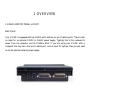
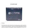
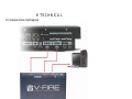
V-FIRE
User’s Manual
Version 1.0
PreSonus Audio Electronics, Inc., © 2006
PreSonus Limited Warranty
PreSonus Audio Electronics Inc. warrants this product to be free of defects in material and workmanship for
a period of one year from the date of original retail purchase. This warranty is enforceable only by the
original retail purchaser. To be protected by this warranty, the purchaser must complete and return the
enclosed warranty card within 14 days of purchase. During the warranty period PreSonus shall, at its sole
and absolute option, either, repair or replace, free of charge, any product that proves to be defective on
inspection by PreSonus or its authorized service representative. To obtain warranty service, the purchaser
must first call or write PreSonus at the address and telephone number printed below to obtain a Return
Authorization Number and instructions of where to return the unit for service. All inquiries must be
accompanied by a description of the problem. All authorized returns must be sent to the PreSonus repair
facility postage prepaid, insured and properly packaged. PreSonus reserves the right to update any unit
returned for repair. PreSonus reserves the right to change or improve the design of the product at any time
without prior notice. This warranty does not cover claims for damage due to abuse, neglect, alteration or
attempted repair by unauthorized personnel, and is limited to failures arising during normal use that are due
to defects in material or workmanship in the product. Any implied warranties, including implied warranties
of merchantability and fitness for a particular purpose, are limited in duration to the length of this limited
warranty. Some states do not allow limitations on how long an implied warranty lasts, so the above
limitation may not apply to you. In no event will PreSonus be liable for incidental, consequential or other
damages resulting from the breach of any express or implied warranty, including, among other things,
damage to property, damage based on inconvenience or on loss of use of the product, and, to the extent
permitted by law, damages for personal injury. Some states do not allow the exclusion of limitation of
incidental or consequential damages, so the above limitation or exclusion may not apply to you. This
warranty gives you specific legal rights, and you may also have other rights, which vary from state to state.
This warranty only applies to products sold and used in the United States of America. For warranty
information in all other countries please refer to your local distributor.
PreSonus Audio Electronics, Inc.
7257 Florida Blvd.
Baton Rouge, LA 70806
www.presonus.com
Table of Contents
1 Overview
1.1 Introduction ...................................................................................................... 4
1.2 What is in the Box............................................................................................. 5
1.3 Back and Top Panel Layout ............................................................................... 6
2 Installation
2.1 Computer Requirements..................................................................................... 8
2.2 Installation........................................................................................................ 9
3 Control Panel
3.1 Control Panel Operation .................................................................................. 12
4 DAW Set Up
4.1 General DAW Set Up for V-FIRE Operation..................................................... 13
5 Roland VS Settings for V-FIRE Operation
5.1 VS-2480CD/DVD ............................................................................................ 14
5.2 VS-2400CD .................................................................................................... 16
5.3 VSR-880......................................................................................................... 19
5.4 VM-3100 Pro ................................................................................................. 20
5.5 XV-5080......................................................................................................... 21
5.6 MV-8000 ........................................................................................................ 21
5.7 VM-7000 ........................................................................................................ 23
6 Technical
6.1 Sample Hook Up Diagram ............................................................................... 25
6.2 Troubleshooting............................................................................................... 26
6.3 Specifications.................................................................................................. 27
1 OVERVIEW
1.1 INTRODUCTION
Thank you for purchasing the PreSonus V-FIRE. PreSonus Audio Electronics has designed the
V-FIRE utilizing high-grade components to insure optimum performance that will last a
lifetime. The V-FIRE is a 24 bit/96k R-BUS to FireWire computer recording system for both
Windows XP and Apple OSX . The V-FIRE allows users to convert Roland’s R-BUS digital
audio format to FireWire ( IEEE 1394), thus providing a multi-channel computer interface for
most Roland products equipped with R-BUS output.
The V-Fire features two R-BUS ports and two FireWire ports allowing sixteen channels of
digital audio to stream at up 24-bit 96K sample rate. The V-FIRE has LED indicators for RBUS1, R-BUS 2 and master sync.
The V-FIRE is accessed via a software control panel enabling the user to select the sample
rate(44.1K,48K,88.2K and 96K), latency, buffer size and clock source.
We suggest that you use this manual to familiarize yourself with the features, applications and
correct connection procedure for your V-FIRE before trying to connect it to your computer.
This will hopefully alleviate any unforeseen issues that you may encounter during installation
and set up.
We encourage you to contact PreSonus customer support at 1-225-216-7887 with any
questions or comments you may have regarding your PreSonus V-Fire. There is also a Glossary
of Terms located in the back of this manual. Most of the technical terms in this manual are
defined in the Glossary for quick reference.
Thank you, once again, for buying our product and we hope you enjoy your V-FIRE!
4
1 OVERVIEW
1.2 WHAT IS IN THE BOX
Your V-FIRE package contains the following:
•
V-FIRE Interface
•
Driver and Control Panel CDROM ( need image)
•
1 FireWire cable
•
1 R-BUS Cable
•
Warranty Card
5
1 OVERVIEW
1.3 BACK AND TOP PANEL LAYOUT
Back Panel
Your V-FIRE is equipped with two R-BUS ports and two six pin FireWire ports. There is also
an input for an optional 12VDC or 16VAC power supply. Typically the V-Fire receives its
power from the computer via the FireWire BUS. If you are using your V-FIRE with a
computer that only has a four pin FireWire port, such as most PC laptops, then you will need
to use the optional external power supply.
6
1 OVERVIEW
Top Panel
The top panel of the V-FIRE has status LEDs for the presence of data on R-BUS 1 and R-BUS
2 as well as the LED indicating sync. Proper driver sync prevents digital interfaces from having
pops, clicks, or distortion in the audio signal. The Sync LED will alternately flash blue and red
when looking for sync. When sync is achieved the LED is a steady blue.
7
2 INSTALLATION
2.1 COMPUTER REQUIREMENTS
Below are the required computer system specs for your V-FIRE:
Windows
- OS: Microsoft Windows XP Service Pack 1 or later
- Computer: Windows compatible computer with 1394 port (PCI or built-in)
- CPU/Clock: Pentium, 1.6MHz or higher
- Memory (RAM): 512 MB (1GB recommended)
Macintosh
- OS: Mac OSX 10.3.7 or later
- Computer: Apple Macintosh series with 1394 port (PCI or built-in).
- CPU/Clock: PowerPC G4/1.2Mhz or higher, all Intel/Mac models
- Memory(RAM): 512 MB (1GB recommended)
Note that the speed of your processor, amount of RAM and size and speed of your hard drive
will greatly affect the overall performance of your recording system.
8
2 INSTALLATION
2.2 Installation
PC:
The following is a detailed procedure for installation of your V-FIRE Drivers:
*YOU MUST INSTALL DRIVERS BEFORE CONNECTING YOUR V-FIRE*
1.) Quit all currently running applications.
2.) Insert the Driver CD included with your V-FIRE into your computer. (Do not connect your
V-FIRE to the computer at this time).
3.) CD should auto run.* (If not, navigate to CD and double click on V-FIRE_Installer.exe)
*There are several parts to the installation of
your V-FIRE. The installer will take you
through each step. Please read each message
carefully as the time at which you connect and
power on your V-FIRE for the first time is
critical to a successful installation.
*If at any point during installation a “Software
Installation” message appears from Windows
regarding Windows Logo testing click
“Continue Anyway” to continue installation.
9
2 INSTALLATION
4.) When prompted to restart your computer, do so.
5.) Once the computer has restarted, connect your V-FIRE to the computer via FireWire .
6.) A windows Found New Hardware Wizard should open. Select ‘No, not this time’, when
prompted to connect to the internet for Windows to find a driver. Click Next.
7.) The next window that comes up should identify the PreSonus Driver and allow you to
choose ‘Install Software Automatically’. Click Next.
8.) Click on Finish when the next window opens. You should now see a blue sync light on your
V-FIRE, indicating that it is sync with your computer and ready to use.
Note: The V-FIRE Control Console application can be found in the Start Menu/ All
Programs/ PreSonus Drivers/ V-FIRE CPL.
Mac:
*YOU MUST INSTALL DRIVERS BEFORE CONNECTING YOUR V-FIRE*
1.) Quit all currently running applications.
2.) Insert the Driver CD included with your V-FIRE into your computer. (Do not connect your
V-FIRE to the computer at this time).
3.) CD should auto run.* (If not, navigate to CD and double click on V-FIRE_Installer.exe)
*There are several parts to the installation of your V-FIRE. The installer will take
you through each step. Please read each message carefully as the time at which you
10
2 INSTALLATION
connect and power on your V-FIRE for the first time is critical to a successful
installation.
4.) When prompted with the Software License Agreement, click Continue, and then click
Agree.
5.) Select the destination volume to install the V-FIRE software, typically ‘Macintosh HD’, and
click Continue.
6.) Click on Install, and when the software installation is complete, click Close.
7.) You can now connect your V-FIRE via the supplied FireWire cable and turn it on. You
should see a blue sync light on the V-FIRE, indicating it is in sync with the computer, and
ready to use.
Note: The V-FIRE Control Console software can be found in the Applications folder
(unless saved elsewhere), and is called‘ V-FIRE’.
11
3 CONTROL PANEL
3.1 CONTROL PANEL OPERATION
Windows XP view of Control Panel:
Macintosh OSX view of Control Panel:
The V-Fire Control Panel is where you set the master clock and choose your sample rate. In
Windows XP you can also set the latency or buffer size in samples.
12
4 DAW SET UP
4.1 General DAW Set Up for V-FIRE Operation
The instructions in this section are provided as general settings to set you DAW software to
work properly with the V-FIRE. Please refer to the Owner’s Manual of the specific software
you are using for a better understanding of the routing and clocking possibilities.
Note: In these examples, the V-FIRE is set to be the master clock. The Roland product is
slaved to the V-FIRE.
Here are the general steps in setting your V-FIRE to run as the Master clock source:
1. Set V-FIRE control panel to INTERNAL.
2. Set V-FIRE control panel sample rate to the same sample rate as your DAW session
AND your Roland product.
3. Make sure PreSonus V-FIRE ASIO driver is selected in DAW.
4. Define the inputs and outputs to R-BUS ins and outs in your DAW Software
5. Set MIDI to INTERNAL.
6. Refer to your software for further details on recording/playback and external MIDI
devices.
To record 16-tracks of R-BUS digital audio into your DAW:
1. Set up your Roland device to “slave” to the V-FIRE (see Chapter 5).
2. Create session with sixteen record armed tracks assigned to R-BUS inputs.
3. Press Play on your Roland device. (It should now be waiting.)
4. Press Record in your DAW software. Your Roland device should start playing and
your DAW should start recording audio
13
5 ROLAND VS SETTINGS
5 Roland Parameter Settings When Used With the V-Fire
Important: The instructions below are provided as specific steps to setup the Roland device to
work properly with the PreSonus V-Fire. Please refer to the Owner’s Manual of the specific
Roland device for a better understanding of the routing and clocking possibilities when used
with R-Bus devices, such as the V-Fire.
Note: In these examples, the Roland product will be set to clock to the V-Fire.
(i.e. slaved to the digital clock of the V-Fire)
However, digital clock could be set in the opposite direction by leaving the Roland on its
default selection of Internal clock, and setting the V-Fire digital clock to R-Bus1 or R-Bus2 in
the V-Fire software control panel.
5.1 Roland VS-2480CD/DVD, Using the Onboard LCD Screen
Digital Clock (Slave)
Press the Utility Button, and select “3 Project”
Turn the Master Clock setting to R-Bus1 or R-Bus2
[“Digital In Lock” will appear in the screen indicating that the Roland device is locked to the
V-Fire digital clock.]
Set the R-Bus2 Coaxial Select to “R-Bus-2-1/2, R-Bus-2-5/6”
Set the R-Bus2 Optical Select to “R-Bus-2-3/4, R-Bus-2-7/8”
Input to VS-2480
Press EZ ROUTING, and then press F1 for View.
14
5 ROLAND VS SETTINGS
At the top of the screen, attach up to 16 input mixer channels to the 16 R-Bus inputs
(R-Bus1 and R-Bus2) using the cursor buttons and the TIME/VALUE wheel.
Raise the appropriate input mixer channel faders to monitor the incoming audio signals.
Output from VS-2480
Press the EZ ROUTING button.
Press the PAGE button until you see Output over the F3 button.
Press F3 for Output.
Cursor to Track Direct, and use the TIME/VALUE wheel to turn Track Direct ON.
Cursor to the R-Bus Outputs, and use the TIME/VALUE wheel to connect the R-Bus output
pairs with the Track Numbers down the right side of the screen.
This will route individual VS-2480 audio track outputs to the V-Fire inputs via R-Bus.
Alternatively,
Leave Track Direct OFF and connect the R-Bus output pairs at the top of the screen to Auxes,
Directs or Busses of your choice, using the TIME/VALUE wheel.
Roland VS-2480CD/DVD, Using a VGA Monitor
Digital Clock (Slave)
From the Utility menu, select Project Parameter
Set the Master Clock to either R-Bus 1 or R-Bus 2
[“Digital In Lock” will appear in the screen indicating that the Roland device is locked to the
V-Fire digital clock.]
Set the R-Bus 2 Coaxial Select to “R-Bus-2-1/2, R-Bus-2-5/6”
15
5 ROLAND VS SETTINGS
Set the R-Bus 2 Optical Select to “R-Bus-2-3/4, R-Bus-2-7/8”
Input to VS-2480
From the EZ Routing menu, select Routing View
In the Patch Bay section of the screen (top left), attach up to 16 input mixer channels to the
16 R-Bus inputs (R-Bus 1 and R-Bus 2) using the mouse.
Raise the appropriate input mixer channel faders to monitor the incoming audio signals.
Output from VS-2480
From the EZ Routing menu, select Routing View
In the Output Assign section of the screen (Top Right), turn Track Direct to ON.
Use the mouse to connect the R-Bus output pairs on the top of the screen with the Track
Numbers down the right side of the screen.
This will route individual VS-2480 audio track outputs to the V-Fire inputs via R-Bus.
Alternatively,
Leave Track Direct OFF and connect the R-Bus output pairs on the top of the screen to Auxes,
Directs or Busses of your choice, using the TIME/VALUE wheel or mouse.
5.2 Roland VS-2400CD, using the onboard LCD screen
Digital Clock (Slave)
Press SHIFT-F4 to access the Utility menu, and select “3 Project”.
Set the Master Clock to R-Bus.
[“Digital In Lock” will appear in the screen indicating that the Roland device is locked to the
V-Fire digital clock.]
16
5 ROLAND VS SETTINGS
Input to VS-2400CD
Press the EZ ROUTING and press F1 for View.
At the top of the screen, attach up to 8 input mixer channels to 8 R-Bus inputs, using the
cursor buttons and TIME/VALUE wheel.
Raise the appropriate input mixer channel faders to monitor the incoming audio signals.
Note: R-Bus is routed to Input Mixer channels 9-16 by default.
Output from VS-2400CD
Press the EZ ROUTING button.
Press the PAGE button until you see Output over the F3 button.
Press F3 for Output.
Cursor to Track Direct, and use the TIME/VALUE wheel to turn Track Direct ON.
Cursor to the R-Bus Outputs and use the TIME/VALUE wheel to connect the R-Bus output
pairs at the top of the screen with the Track Numbers down the right side of the screen.
This will route individual VS-2400CD audio track outputs to the V-Fire inputs via R-Bus.
Alternatively,
Leave Track Direct OFF and connect the R-Bus output pairs on the top of the screen to Auxes,
Directs, or Busses of your choice, using the TIME/VALUE wheel.
Roland VS-2400CD, Using a VGA Monitor
Digital Clock (Slave)
From the Utility menu, select Project Parameter.
17
5 ROLAND VS SETTINGS
Set the Master Clock to R-Bus.
[“Digital In Lock” will appear in the screen indicating that the Roland device is locked to the
V-Fire digital clock.]
Input to VS-2400CD
From the EZ ROUTING menu, press F1 for View.
In the Patch Bay section of the screen (top left), attach up to 8 input mixer channels to the 8
R-Bus inputs using the mouse.
Raise the appropriate input mixer channel faders to monitor the incoming audio signals.
Note: R-Bus is routed to Input Mixer channels 9-16 by default.
Output from VS-2400CD
From the EZ Routing menu, select Routing View.
In the Output Assign section of the screen (Top Right), turn Track Direct to ON.
Use the mouse to connect the R-Bus output pairs on the top of the screen with the Track
Numbers down the right side of the screen.
This will route individual VS-2400CD audio track outputs to the V-Fire inputs via R-Bus.
Alternatively,
Leave Track Direct OFF and connect the R-Bus output pairs on the top of the screen to Auxes,
Directs or Busses of your choice, using the TIME/VALUE wheel or mouse.
18
5 ROLAND VS SETTINGS
5.3 Roland VSR-880
Digital Clock (Slave)
Press SHIFT+SYSTEM until you see SYSTEM PRM, and press ENTER.
Use Parameter buttons to select the MasterClk screen.
Use the TIME/VALUE Knob to set MasterClk to “R-BUS”.
[“Digital In Lock” will appear in the screen indicating that the Roland device is locked to the
V-Fire digital clock.]
Output from VSR-880
Press LEVEL/BALANCE.
Use PARAMETER buttons to select the “MST Direct Out” screen.
Use the TIME/VALUE Knob to set Direct Out to ON.
Input to VSR-880
Press SHIFT + IN MIX (LEVEL/BALANCE).
Use PARAMETER buttons to select the “Input =” screen.
Use the TIME/VALUE Knob to set Input = R-Bus.
To do this for each input, you’ll need to hold SHIFT and press the STATUS button for every
odd-numbered input, one at a time. (Note: The inputs are adjusted in pairs.)
Change each odd-numbered input to R-Bus, …the even-numbered input will also be set to RBus.
19
5 ROLAND VS SETTINGS
5.4 Roland VM-3100 Pro
Note: The VM-3100 Pro operates at a sampling rate of 44.1 kHz only. The 44.1 kHz
sampling rate should be selected in the V-Fire control panel software.
Digital Clock (Slave)
Press the SYSTEM Button.
Cursor down to the “MasterClk” screen and select RMDB-2.
[“Digital In Lock” will appear in the screen indicating that the Roland device is locked to the
V-Fire digital clock.]
Input to VM-3100 Pro
Channels 9-16 are your R-Bus audio returns. Access these by pressing the AUDIO CH button
until it is green.
Output from VM-3100 Pro
Press the EZ ROUTING button.
Press the F1-F4 ON/OFF button.
Select OUTPUT by pressing F2.
Use the CURSOR RIGHT button right to select the outputs for each track. Make the following
settings with the Time/Value wheel…
Tr 1/2 = CH01/02
Tr 3/4= CH03/04
Tr 5/6 = CH05/06
Tr 7/8= CH07/08
20
5 ROLAND VS SETTINGS
5.5 Roland XV-5080
Note: The XV-5080 only supports audio outputs via R-Bus, not inputs.
Digital Clock (Slave)
Press SYSTEM.
Press F2 (Outp&EQ)
Change Master Clock to “R-Bus”
Change Master Freq to match the Sampling Rate you will use.
[External Clock will change to “In Lock” in the screen indicating that the Roland device is
locked to the V-Fire digital clock.]
Change the Output Mode to Parallel.
Output from XV-5080
Press PERFORM.
Press F5(Effects).
For each part, select the output you wish to use.
The numbers 1-8 correspond to individual R-Bus channels 1-8.
Letters A – D are pairs of R-Bus Channels. (i.e. A is R-Bus 1/2, B is R-Bus 3/4, etc.)
5.6 Roland MV-8000, Using the Onboard LCD Screen
Digital Clock (Slave)
Press SYSTEM and cursor to R-Bus.
Press ENTER.
Cursor to Word Clock, and use the VALUE Wheel to select External.
21
5 ROLAND VS SETTINGS
Cursor to Message Type, and use the VALUE Wheel to select R-Bus.
[“Digital In Lock” will appear in the screen indicating that the Roland device is locked to the
V-Fire digital clock.]
Input to MV-8000
Press SAMPLING.
Cursor to Input Select, and use the VALUE Wheel to select R-Bus.
The MV-8000 will use R-Bus channels 1&2 for its input.
Output from MV-8000
Press MIXER.
Cursor to Output at the bottom of each mixer channel, and select Mlt 1-8 for individual R-Bus
channels 1-8, or M1/2 – M7/8 for stereo pairs of R-Bus channels.
Roland MV-8000, Using a VGA Monitor
Digital Clock (Slave)
Click the SYSTEM menu, and select “7 R-BUS”.
Change Word Clock to External, and change Message Type to R-Bus.
Click on Input Select, and change it to R-Bus.
[“Digital In Lock” will appear in the screen indicating that the Roland device is locked to the
V-Fire digital clock.]
The MV-8000 will use R-Bus channels 1&2 for its input.
22
5 ROLAND VS SETTINGS
Input to MV-8000
Click on the Sampler menu, and select Sampling.
Click on Input Select, and choose R-Bus.
Output from MV-8000
Click the Mixer/Effects menu.
Click “1 Mixer”.
Click OUTPUT at the bottom of each mixer channel, and select Mlt 1-8 for individual R-Bus
channels 1-8, or M1/2 – M7/8 for stereo pairs of R-Bus channels.
5.7 Roland VM-7000 Series
Digital Clock (Slave)
Press SHIFT+SYSTEM(PROJECT).
Cursor down and press F1 - DIGITAL I/O
Change Word Clock Source to Multi 1-8
Make sure the Internal Sampling Rate matches your computer settings.
[“Digital In Lock” will appear in the screen indicating that the Roland device is locked to the
V-Fire digital clock.]
Input to VM Series
The Multi In channels receive digital audio signals from the V-Fire’s R-Bus outputs.
Press the MULTI IN CH1-24 button, verify that each appropriate channel is On and not
muted, then raise the appropriate Multi In channel faders to monitor the incoming audio
signals.
23
5 ROLAND VS SETTINGS
Output from VM Series
The Multi Outs feed audio signal to the V-Fire’s R-Bus inputs.
Each input channel on a VM-7000 series mixer can assign its audio signal to 1 or more Multi
Outs (R-Bus or Analog).
Usually, the default Patch bay setting would be the best option for use with the V-Fire
(Input channel 1 sending to Multi Out 1, Input channel 2 sending to Multi Out 2, etc.), but this
can easily be changed by the user.
To change channel routings to the Multi Outs…
Press the Multi Out 1-24 button.
Press the desired CH EDIT button of the MULTI OUT to be re-routed.
Turn the V1 Value knob to change the Source Select value of the appropriate input channel to
be routed to the chosen MULTI OUT destination.
The MULTI OUT level can be adjusted with the appropriate fader or the V2 Value knob.
For more advanced routing options and settings, please refer to the VM-7000 series Owner’s
Manual.
24
6 TECHNICAL
6.1 Sample Hook-Up Diagram
25
6 TECHNICAL
6.2 Troubleshooting
Please note that many technical issues can arise when connecting an external audio device to a
computer. PreSonus will only provide support for issues that directly relate to your V-FIRE. It
may be necessary to contact the manufacturer of the computer, operating system and/or
software to obtain additional technical support. PreSonus does not provide support for issues in
regards to operating systems, additional hardware or software.
Please check our website, www.presonus.com regularly for software information and updates,
firmware updates, and technical support. Also, technical assistance may be received by calling
PreSonus at 225-216-7887 between the hours of 9 am and 5 PM Central Standard Time, or
by emailing [email protected].
When contacting technical support, please have the following information at hand:
•
What Operating System and version (ex; Mac OSX 10.4.7) are you running?
•
Have you successfully installed the V-FIRE drivers on your computer?
•
What color is the sync light on your V-FIRE when connected to the computer via the
supplied FireWire Cable and powered on?
•
Is the FireWire connection on your computer built-in (supplied on the motherboard)
or through a PCI/PCMCIA card?
•
What, if any, other FireWire Devices do you have connected to the computer?
•
What, if any, DAW software (Cubase, Logic, Sonar, etc.) are you using with your
V-FIRE?
26
6 TECHNICAL
6.3 Technical Specifications
Digital Audio Transfer ............................................................ R-BUS to FireWire (IEEE 1394)
Maximum Inputs/Outputs........................................................................... 16 inputs/ 16 outputs
Supported Sample Rates.......................................................................... 44.1, 48, 88.2, 96kHz
Control Panel Parameters....................................Sample Rate, Latency (PC only), Clock Source
R-BUS 1 ...................................... 8 channels digital audio input/output with full R-BUS support
R-BUS 2 ...................................... 8 channels digital audio input/output with full R-BUS support
Power Supply ............................................Ext line Transformer, Internal Switching, 12-18V DC
Bus Power................................................................................................ Six-pin FireWire Port
As a commitment to constant improvement, PreSonus Audio Electronics, Inc. reserves the
right to change any specification stated herein at any time in the future without notification.
27