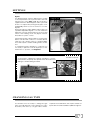
1
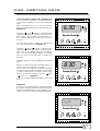
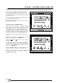
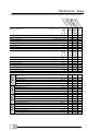
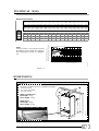
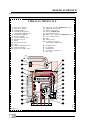
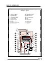
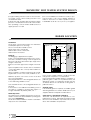
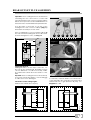
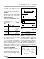
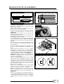
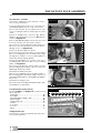
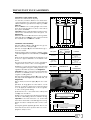
THELIA
THIS IS A CAT II2H3+ APPLIANCE
IN WARRANTY
TECHNICAL HELPLINE
01773 828400
01773 828100
1
INSTALLATION AND OPERATING INSTRUCTIONS
THELIA 23, THELIA 23 E, THELIA SB 23
Note!
The boiler serial number is marked on the label attached to the inside of the door. Refer to the
“Introduction” section page 3 for a description of the basic functions of the boiler. The “Users”
section describes how to safely operate the boiler.
USERS SECTION
INSTALLATION SECTION
Introduction .................................................. Page 3
Commisioning ........................................................ 3
Controls & lighting ................................................. 4
Operation - Checks ............................................... 5
Clock - instructions for use ............................... 6 - 8
Draining ................................................................... 9
Servicing/maintenance ........................................ 9
Introduction .................................................. Page 3
Technical data .............................................. 10 - 11
Dimensions ............................................................ 11
Boiler schematic ........................................... 12 - 13
Connection plate ................................................ 14
Piping system installation .................................... 15
Heating system design ........................................ 15
Hot water system design ..................................... 16
Boiler location ............................................... 16 - 17
Boiler installation .................................................. 18
Flue installation .............................................. 18 - 23
Electrical connection ................................... 24 - 25
Commissioning .............................................. 26 - 27
Operating safety devices ................................... 28
Settings ........................................................... 28 - 29
Changing gas type ............................................. 29
Mandatory warning notice for CEE countries
WARNING, this appliance was designed, approved and inspected to meet the requirements of the
English market. The identification plate located on the inside of the appliance certifies the origin
where the product was manufactured and the country for which it is intended.
If you see any exception to this rule, please contact your nearest Saunier Duval dealer.
Thank you in advance for you assistance.
2
INTRODUCTION
The Thelia 23 and Thelia 23E range of boilers are
wall mounted combination boilers providing central heating and instantaneous domestic hot water.
The Thelia SB23 boiler is a wall mounted boiler providing central heating only. This boiler can be used
in combination with a hot water tank to supply
domestic hot water.
The boilers are of the II2H3+ Gas Category for use
with natural gas (G20) as distributed in the United
Kingdom or with butane or propane gas (G30/31).
These instructions should be carefully followed for
the safe and economical use of your boiler.
Once the pilot has been lit (Thelia 23 and Thelia
SB23 only) the boiler is automatic in operation.
The boilers have a fan assisted balanced flue
which both discharge the products of combustion
to and draws the combustion air from the outside
air.
The boiler is supplied for rear outlet flue connection.
Alternatively, the boiler is designed to allow the
flue system to be connected to the top of the
boiler, top outlet flue connection. Refer to the flue
fitting instructions.
The boilers can be installed on either an external
wall or on an adjacent inside wall, that is, the flue
system will pass directly to the rear or to either side
to the terminal fitted on the outside wall face.
Ancillary equipment
A range of accessories are available including, vertical flue coponents, bends ....
For further information contact your supplier.
Boilers burning LPG or similar gas MUST NOT be
fitted in basements or below ground level.
COMMISSIONING
Gas Safety (Installation and Use) Regulations
In your interests and that of gas safety, it is the law
that ALL gas appliances are installed and serviced
by a competent person in accordance with the
above regulations.
Gas leak or fault
If a gas leak or fault exists or is suspected, turn the
boiler off and consult the local gas undertaking or
your installation/servicing company.
Boiler controls
The control panel, located at the lower front of
the boiler casing allows the boiler to be started,
shut down, controlled and monitored during use,
see diagram 2 (Thelia 23 and Thelia 23E) or diagram 3 (Thelia SB23).
Flue
Do not obstruct the outside terminal of the boiler.
Note. At stand-by, the boiler fan will run at low
speed, this is quite normal.
Starting the boiler
Before starting the boiler check that:
- The gas meter tap is open. If using butane or propane, check that valve on storage cylinder or tank
is open.
- The boiler gas service cock is open.
- The boiler is connected to the electrical supply
and switched on.
- The selector lever is in the left hand position.
3
CONTROLS AND LIGHTING
Lighting the THELIA 23 and THELIA SB 23 boilers
Diagram. 1
2 - The pilot lights.
Check that pilot
is alight by looking through the
viewing window.
1 - Push in and hold
OPENING THE CONTROL PANEL COVER
Hab 129
1 / ON
4 - Release : the
pilot must remain
ON, if the pilot
does not remain
lit, repeat the
previous steps.
3 - Wait for
20 seconds
+
The control panel, located at the lower front of the
boiler casing diag. 1 allows the boiler to be started,
shut down, controlled and monitored during use.
1 / ON
Note : On pressing the ‘ON’ button, the fan will be heard
to run at full speed after which the ignition sequence will
start and the pilot will light.
Should the pilot fail to remain alight or go out for any
reason, intentionally or unintentionally, always wait at
least 3 minutes before trying to relight.
Control panel description (diag. 2 and 3) :
1 - "ON" push - button.
2 - "OFF" push - button.
4 - Boiler thermostat.
5 - Temperature gauge.
6 - Pressure gauge.
7 - Summer - Winter lever (THELIA 23, THELIA 23 E).
Summer - Winter switch (THELIA SB 23).
30 - Domestic hot water temperature
adjustment.
Lighting the THELIA 23 E boiler
Hab 130
Push in and release
1 / ON
BOILER CONTROL PANEL THELIA 23, THELIA 23 E
Diagram. 2
5
6
7
4
30
2
1
4
3
2
1
0
50
30
70
90
110
bar
1 / ON
Hab 043a
0 / OFF
BOILER CONTROL PANEL THELIA SB 23
Diagram. 3
7
6
5
4
2
1
4
3
2
1
0
bar
4
50
30
70
90
110
1 / ON
Hab 044a
0 / OFF
OPERATION - CHECKS
THELIA SB 23
THELIA 23, THELIA 23 E
HEATING + HOT WATER
● Place the selector lever (diagram. 4)
to
position (winter). In this position the domestic
hot water will have PRIORITY.
Diagram. 4
HEATING ONLY
Turn the selector switch (diagram. 8)
to
position (winter).
●
Hab 128
Hab 131
Diagram. 8
Reg 012
Diag. 5
Heating : turn the knob
(diagram. 6) in order to
obtain a water temperature suited to the demand, and adjust the
room thermostat to the
desired temperature.
●
● Heating : turn the knob
(diagram. 9) in order to
obtain a water temperature suited to the demand, and adjust the
room thermostat to the
desired temperature.
Diag. 9
Reg 012
Hot water : Turn the
knob (diagram. 5) in order to obtain a water
temperature suited to
the demand.
●
Note : If you are out for a few days, set the button
(diagram. 9) to the minimum value in order to
protect the boiler from frost. In case of prolonged
absence, refer to “Draining” section page 9.
Reg 012
Diag. 6
Note : If you are out for a few days, set the button
(diagram. 6) to the minimum value in order to
protect the boiler from frost. In case of prolonged
absence, refer to “Draining” section page 9.
ALTERNATIVE OPERATING MODE THELIA SB 23
You may select the operating mode using the
switch (diagram. 8) :
Winter
Heating only
Summer
HOT WATER ONLY
Place the selector lever (diagram. 4)
to
position (summer).
Heating is switched OFF. The boiler will provide hot
water only. Turn the knob (diagram. 5) in order to
obtain a water temperature suited to the
demand.
Domestic hot water only mode.
The boiler will keep the separate
storage cylinder, where fitted, at
the desired temperature.
Winter
Heating and domestic hot water
mode
STOPPING THE BOILER
Press the (O/OFF)
push-button (diagram. 7) : this will close OFF the gas supply
valve. Electrical power
supply to the boiler will
be automatically switched OFF.
STOPPING THE BOILER
● Press the (O/OFF)
push-button (diagram. 10) : this will close OFF the gas supply
valve. Electrical power
supply to the boiler will
be automatically switched OFF.
Hab 133
Diag. 10
Hab 133
Diag. 7
➞
●
➞
●
5
CLOCK - INSTRUCTIONS FOR USE
The boiler is connected to the electrical supply
and switched on.
IF FITTED, SET THE CLOCK TO WORK, AS THE
INSTRUCTIONS BELOW.
General Description
The timeclock has an internal, factory set
programme which switches the boiler "On" and
"Off" three times a day as below.
1st
ON
06.30
1st
OFF 08.30
2nd ON
12.00
2nd OFF 12.00
3rd
ON
16.30
3rd
OFF 22.30
It also has an advance feature, a hold or holiday
feature, details on how to set these are given
further on in these instructions.
12.00
C1
AUTO
TIMER
Saunier Duval
on
res
off
enter
Diagram. 11
Setting the Time
With the electrical supply to the boiler switched on,
place the slide switch to " ".
Press the "Reset" (res) button for a few seconds, using
a pointed object, such as a pencil. When released
the display will begin to flash, see diagram 11.
13.00
" buttons, set the display to
Using the " "and "
the correct time in twenty four hour format, for
example, 1300 for 1pm, see diagram 12.
Helpful Hint
The " " and " " buttons are used to change
times. Press and release for small changes. If you
press and hold down the time will "run".
Saunier Duval
on
res
off
To Set the Programme "On" and "Off" Times
At this stage, if you want to use the internal, factory
set, programmes simply place the slide switch to
"Auto". The display will show the current time. The
"On" or "Off" symbol will be shown according to the
time of day.
To Override or Advance the Timeclock
To advance the time clock operation, that is,
switch the heating "On" when it is "Off" or the other
way round, press the "On/Off" button. The timeclock
will switch the heating "On" or "Off" as desired and
the "On" or "Off" symbol will flash to show that it has
been overridden. See diagram 13.
Note. The boiler will stay "On" or "Off", as selected,
until the timeclock programme reaches its next
"On" or "Off" time. From then on, the timeclock will
switch the boiler "On" and "Off" according to the
internal programme. When the boiler is again
controlled by the internal programme the "On" or
"Off" symbol will stop flashing. The timeclock
operation can be overridden in this way at any
time.
6
C1
AUTO
TIMER
enter
Diagram. 12
7.50
ON
C1
AUTO
TIMER
Saunier Duval
on
res
off
Diagram. 13
enter
CLOCK - INSTRUCTIONS FOR USE
To Set Your Own Programme "On" and "Off" Times
Note. The timeclock can be set to give a minimum
of one and a maximum of three "On" and "Off"
times.
Place the slide switch to "C1". Press the "Enter"
button. The display will show the first "On" time, see
diagram 14.
Using the "
" and "
" buttons, change the first
"On" time to the time you require. Press the "Enter"
button twice. This stores the new time and shows
it to confirm it has been stored in the timeclock
memory.
Press the "Enter" button again. The display will
show the first "Off" time, see diagram 15.
6.30
ON
C1
AUTO
TIMER
Saunier Duval
on
res
off
enter
Diagram. 14
Using the "
" and "
" button, change the first
"Off" time to the time you require. Press the "Enter"
button twice. The display will show the first "On"
time. Press the "Enter" button again. The display
will now show the first "Off" time you have just
entered.
Repeat the above for the remaining "On" and "Off"
times.
8.30
When you have set the "On" and "Off" times you
require, place the slide switch to "Auto".
Note. If you do not want to set all three "On" and
"Off" times, follow the above instructions, but, after
you have set the times you require, set the other
times to show a series of dashes, using the "
" and
" button, see diagram 16.
"
The series of dashes are between times 23.59 and
0.00.
OFF
C1
AUTO
TIMER
Saunier Duval
on
res
off
enter
Diagram. 15
Helpful Hint.
If you get confused and wish to start again, press
the "Reset" (res) button and the timeclock will go
back to the internal factory set programme. You
can now reset the current time and start again.
-.--
ON
C1
AUTO
TIMER
Saunier Duval
on
res
off
enter
Diagram. 16
7
CLOCK - INSTRUCTIONS FOR USE
To Check the Programme "On" and "Off" Times
The programmed "On" and "Off" times can be
checked at any time by moving the slide switch
from "Auto" to "C1".
- H
Successive presses of the "Enter" button will then
show the "On" and "Off" times.
Always return the slide switch to "Auto" to return to
normal timed working.
OFF
C1
AUTO
TIMER
Saunier Duval
To Set the "Hold" or "Holiday" Feature
The timeclock has a "Hold" or "Holiday" feature
which can be set, if required, to keep the central
heating "On" or "Off" for a period between one
hour and twenty seven days. This can be used, for
example to keep the central heating "Off" during
a holiday. After the programmed time has gone
by, the boiler returns to its normal programmes.
on
res
off
enter
Diagram. 17
To set the "Hold" or "Holiday" feature carry on as
follows:
Place the slide switch to "Timer", the letter "h" will
appear on the display, see diagram 17.
" and "
Using the "
time required.
After a hold period of twenty three hours has been
exceeded, the "h" symbol on the display will change
to a "d". The "hold" time will now be in days, instead
of hours, see diagram 18.
Use the "On/Off" button to set the boiler to the
required operation during the "Hold" period.
Place the slide switch to "Auto". After the
programmed hold time, the boiler will return to
normal timed working.
8
13
" buttons, set the “Hold”
OFF
C1
AUTO
TIMER
Saunier Duval
on
res
off
Diagram. 18
enter
DRAINING
Protection against freezing
If the boiler is to be out of use for any long periods
during severe weather conditions, it is recommended that the whole system, including the
boiler, be drained to avoid the risk of freezing.
If in doubt, consult your servicing company.
Draining and filling
Caution : the boiler is installed as part of a sealed
system which must only be drained and filled by a
competent person.
Note : If there is persistent loss of system pressure,
indicated by the pressure gauge, you must contact the installer or servicing company.
Safety valve
CAUTION. A safety valve with a discharge pipe is
fitted to this boiler.
The valve MUST NOT BE TOUCHED except by a
competent person. If the valve discharges at any
time, switch the boiler off and isolate it from the
electrical supply. Contact your installation/servicing company.
SERVICING/MAINTENANCE
To ensure the continued efficient and safe
operation of the boiler it is recommended that it is
checked and serviced at regular intervals. The
frequency of servicing will depend upon the installation conditions and usage but, in general,
once a year should be enough
Cleaning
The boiler casing can be cleaned with a damp
cloth followed by a dry cloth to polish.
Do not use abrasive or solvent cleaners.
Boiler casing
CAUTION. Do not remove or adjust the casing in
any way, as incorrect fitting may result in faulty
operation. If in doubt contact your installation/
servicing company.
9
TECHNICAL DATA
23
Heating regulation
SB
Heating max. output temperature
A
Efficiency
E
(kW)
(BTU/H)
to...
(kW)
(BTU/H)
ELI
23
23
adjustable from...
TH
A
ELI
TH
A
ELI
TH
Heating useful output,
8,9
8,9
8,9
30,000 30,000 30,000
23,3
23,3 23,3
80,000 80,000 80,000
(%)
82,3
82,3
82,3
(°C)
87
87
87
adjustable by user between 30 and 87°C
Heating system expansion vessel, effective capacity
(l)
6,5
6,5
6,5
System max. capacity at 75°C
(l)
140
140
140
Safety valve, maximum service pressure
(bar)
Products outlet
Fresh air inlet
Output in hot water mode,
(Ø)
3
3
60
60
(Ø)
(kW)
(BTU/H)
to...
(kW)
100
100
8,9
8,9
30,000 30,000
23,3
23,3
100
—
—
—
(BTU/H)
80,000 80,000
—
automatically variable from...
Max. hot water temperature
3
60
(°C)
65
65
—
Operating threshold flow rate in sanitary hot water mode
(l/min.)
3
3
—
Specific flow rate (for 30°C temperature rise)
—
(l/min.)
11
11
Mini. supply pressure
(bar)
0,3
0,3
—
Max. supply pressure
(bar)
10
10
—
(V)
230
230
230
Amperage
(A)
0,73
0,73
0,73
Max. power absorbed
(W)
130
130
130
Natural Gas
(G20)
Electrical supply
Ø Pilot injector
(mm)
0,28
—
0,28
Ø Burner injector
(mm)
1,20
1,20
1,20
Inlet pressure
(mbar)
20
20
20
Gas rate (maximum)
(m3/h)
2,70
2,70
2,70
Gas rate (minimum)
(m3/h)
1,13
1,13
1,13
(mm)
0,18
—
0,18
(mm)
0,73
Butane
(G 30)
Ø Pilot injector
Ø Burner injector
0,73
0,73
(mbar)
29
29
29
Gas rate (maximum)
(kg/h)
2,01
2,01
2,01
Gas rate (minimum)
(kg/h)
0,84
0,84
0,84
(mm)
0,18
—
0,18
(mm)
0,73
Inlet pressure
Town gas
(G130)
Propane
(G31)
Ø Pilot injector
10
Ø Burner injector
0,73
0,73
(mbar)
37
37
37
Gas rate (maximum)
(kg/h)
1,98
1,98
1,98
Gas rate (minimum)
Inlet pressure
(kg/h)
0,83
0,83
0,83
Ø Pilot injector
(mm)
—
—
—
Ø Burner injector
(mm)
—
2,40
—
Inlet pressure
(mbar)
—
8
—
Gas rate (maximum)
(m3/h)
—
3,88
—
Gas rate (minimum)
(m3/h)
—
1,63
—
TECHNICAL DATA
Burner pressure (mbar)
Heat output
(kW)
8,9
10
11
12
13
14
15
16
17
18
19
20
21
22
23,3
(Btu/h) 30387 34142 37557 40971 44385 47799 51214 54628 58042 61456 64871 68285 71699 75113 79552
Heat input
(kW)
11,9 13,1 14,2 15,3 16,4 17,5 18,7 19,9 21,1 22,2 23,4 24,6 25,6 26,8 28,3
(Btu/h) 40678 44631 48410 52326 56042 59742 63794 67819 71897 75872 79910 83836 87545 91412 96602
GAS
(mbar)
1,8
2,2
2,6
3,1
3,5
4,0
4,5
5,1
5,8
6,4
7,1
7,8
8,5
9,3
10,4
G 30
(mbar)
4,1
5,0
5,9
6,8
7,8
8,9
10,2
11,5
12,9
14,4
15,9
17,5
19,1
20,9
23,3
G 31
(mbar)
5,3
6,4
7,5
8,7
10,0
11,4
13,0
14,7
16,5
18,4
20,4
22,4
24,5
26,7
29,8
G 130
(mbar)
0,5
0,6
0,7
0,8
0,9
1,0
1,2
1,3
1,5
1,7
1,8
2,0
2,2
2,4
2,7
by pass fully closed
5
4
3
open 1 tu
rn
open 2 turn
s
open 3 turns
by pass fully open
2
1
500
0
1000
Pom 023
Pump
The performance of the pump, running
at maximum speed, varies according to
the pump bypass setting, see diagram
19.
Pressure loss between flow and
return boiler connections (metres head)
G 20
Water flowrate (l/h)
Diagram. 19
DIMENSIONS
Diagram. 20
23
4
The boiler is delivered in three separate packages :
- the boiler itself
- its connection plate
- the flue system.
623
802
THELIA SB 23
Net weight : 40 kg
Gross weight : 42 kg
857
THELIA 23, THELIA 23 E
Net weight : 41 kg
Gross weight : 43 kg
Hab 132
Hab 129
OPENING THE CONTROL PANEL COVER
410
37
8
11
BOILER SCHEMATIC
THELIA 23, THELIA 23 E
-
5678910 11 12 13 14 -
"ON" push - button.
"OFF" push - button.
Spark generator.
Central heating water
temperature adjustment.
Temperature gauge.
Pressure gauge.
Summer - Winter lever.
Expansion vessel.
Pump.
Automatic air vent.
Burner.
Heat exchanger air vent.
Heat exchanger.
Multi - functional control.
15 16 17 18 19 20 21 22 23 30 A
B
C
D
F
12
- Heating return
- Cold water
- Heating flow
- Domestic hot water out
- Gas inlet
23
19
22
18
13
17
12
16
20
15
11
14
10
6
9
5
8
3
7
2
30
1
21
4
A
Diagram. 21
Safety electrovalve (THELIA 23 E only).
Hight limit thermostat.
Ignition electrode.
Pilot (not THELIA 23 E)
Hot water thermistor.
Flame sense electrode (THELIA 23 E only).
Loss of water switch.
Fan.
Airflow switch.
Domestic hot water
temperature adjustment.
B
C
D
F
Shy 067a
1
2
3
4
BOILER SCHEMATIC
THELIA SB 23
-
568910 11 12 13 -
14 16 17 18 19 21 22 23 -
"ON" push - button.
"OFF" push - button.
Spark generator.
Central heating water
temperature adjustment.
Temperature gauge.
Pressure gauge.
Expansion vessel.
Pump.
Automatic air vent.
Burner.
Heat exchanger air vent.
Heat exchanger.
Multi - functional control.
Hight limit thermostat.
Ignition electrode.
Pilot
Hot water thermistor.
Loss of water switch.
Fan.
Airflow switch.
A - Heating return
C - Heating flow
F - Gas inlet
23
19
22
18
13
17
12
14
11
6
10
5
9
4
8
3
16
2
21
1
A
C
Shy 068a
1
2
3
4
F
Diagram. 22
13
CONNECTION PLATE
Diagram. 23
THELIA 23, THELIA 23 E
5
5
From left to right, the connection plate is equipped with :
A - Heating return with isolating valve (m).
B - Cold water inlet with isolating valve (p).
C - Heating flow with isolating valve (q), drain
screw (r) and safety valve (s).
D - Domestic hot water out.
3
11
E - Electrical connector.
F - Gas service cock.
23
5
5
,5
7
5
34
25
2
1
m
p
4
3
A
r
5
B
Pla 105a
Filters and washers :
1 - Fibre washer
2 - Metal filter
3 - Flow regulator
4 - Plastic filter
5, 6 & 7 - Black graphite
,5
7
5
33
q
s
6
C
7
D
F
E
THELIA SB 23
From left to right, the connection plate is equipped with :
2
25
5
1
1
Filters and washers :
1 - Fibre washer
2 - Metal filter
5 & 7 - Black graphite
23
0
1
1
A - Heating return with isolating valve (m).
C - Heating flow with isolating valve (q), drain
screw (r) and safety valve (s).
3
11
E - Electrical connector.
F - Gas service cock.
m
1
p
r
A
5
q
s
C
7
E
14
Pla 116a
F
PIPING SYSTEM INSTALLATION
Safety valve discharge
WARNING. It must not discharge above an
entrance or window or any type of public access
area.
Connect the safety valve discharge pipe to the
valve, the discharge must be extended, using
not less than 15 mm o.d. pipe, to discharge, in a
visible position, outside the building, facing
downward, preferably over a drain. The pipe
must have a continuous fall and be routed to a
position so that any discharge of water, possibly
boiling or steam cannot create any danger to
persons, damage to property or external
electrical components and wiring. Tighten all
pipe connection joints.
Gas connection
● The supply from the governed gas meter must
be of adequate size to provide a constant inlet
working pressure of 20 mbar (8 in wg).
To avoid low gas pressure problems, it is
Diagram. 24
Ins 016b
Water connection
Connect the water pipes to the fixing jig connecting plate using the copper tails supplied.
Warning : To prevent damage to the isolating
cocks, do not solder joints or fittings with the copper tails connected.
recommended that the supply is connected using
22 mm pipe wherever possible.
● On completion the gas installation must be tested
using the pressure drop method and purged in
accordance with the current issue of BS6891
● Connect the gas supply to the gas service cock
and then the gas service cock to the union on the
gas inlet elbow, see diagram 24.
● If it is an existing LPG installation ensure that it is
capable of providing sufficient additional quantity
of gas.
Gas Safety (Installation and Use) Regulations
In your interests and that of gas safety, it is the law
that ALL gas appliances are installed and serviced
by a competent person in accordance with the
above regulations.
HEATING SYSTEM DESIGN
The boilers are compatible with any type of
installation.
● Heating surfaces may consist of radiators,
convectors or fan assisted convectors.
Caution : if the materials used are of different
types, corrosion phenomena may develop. In
such case, adding a corrosion inhibitor in heating
system water is recommended, in the proportions specified by the manufacturer, to prevent
gas and oxide formation.
● Pipe sectional areas shall be determined in
accordance with normal practices, using the
output/pressure curve (diagram. 19). The distribution system shall be calculated in
accordance with the output corresponding to
the actual system demand, not the maximum
output of that the boiler. However, provision shall
be made to ensure sufficient output so that the
temperature difference between the flow and
return pipes be less than, or equivalent to 20°C.
The minimum flow is 500 l/h.
● The piping system shall be routed so as to avoid
any air pockets and facilitate permanent
venting of the installation. Bleed fittings shall be
●
provided at every high point of the piping system
and on all radiators.
● The total volume of water permitted for the
heating system depends, amongst other things, on
the static head in cold condition. The expansion
vessel integrated into the boiler is pressurised at 0.5
bar in the delivered condition (corresponding to a
static head of 5 m WG) and allows a maximum
volume of 140 litres for an average temperature of
75°C in the radiator system, and a maximum service pressure of 3 bar. This pressure setting can be
modified at boiler commissioning stage if the static
head is different.
● Provision shall be made for a drain valve at
system's lowest point.
● Where thermostatic valves are fitted, not all
radiators must be equipped with this type of valve
and particulary where the room thermostat is
installed.
In the case of an existing installation, it is essential
that the radiator system be thoroughly flushed prior
to installing the new boiler.
15
DOMESTIC HOT WATER SYSTEM DESIGN
Copper tubing must be used for the domestic
hot water system. Unnecessary pressure losses
should be avoided.
● The boiler may operate with a minimum supply
pressure of 0.3 bar, but under reduced flow rate.
Best operating comfort will be obtained from a
supply pressure of 1 bar.
●
● In some installations it will be necessary to provide a means of accommodating expansion
water. A domestic hot water expansion vessel
is available as an accessory from your supplier.
BOILER LOCATION
Fixing jig
The fixing jig is supplied in three parts :
1) The connecting plate which allows the connection and soundness testing of all the pipework
before the boiler is fitted and helps support the
weight of the boiler.
2) The hook which supports the weight of the boiler.
3) The template which ensures the hook and the
connecting plate are correctly fitted relative to
one another.
Place template on wall in required position making allowance for the necessary clearances etc.
Mark the position of the holes for the hook and
the connecting plate.
Drill, plug and fix the connecting plate and hook
to the wall using suitable screws.
Check that both the connecting plate and hook
are level.
If the boiler is not installed immediately, protect
the various couplings to prevent any ingress of
foreign materials E.G. plaster, paint, etc.
Terminal position
The minimum acceptable spacings from the terminal to obstructions and ventilation openings are
as shown in diagram 26.
The boiler must be installed so that the terminal is
exposed to the external air.
16
Diagram. 25
255 mini
4
23
60
29
50
mini
Ins 012a
Clearances
The position of the boiler must be such that there
is adequate space for servicing.
The recommended clearances are:
50mm either side of the boiler.
600mm at the front of the boiler.
300mm below the boiler.
Note. Under certain weather conditions the flue
may produce a plume of condensation.
If the terminal is fitted within 850mm of a plastic or
painted gutter or 450 mm of painted eaves, an
aluminium shield of a minimum length 750 mm
should be fitted to the underside of the gutter or
painted surface.
Terminal guard
If a terminal guard is required, a suitable guard
with integral deflector can be obtained from your
supplier, Saunier Duval part number 85373.
Cupboard or compartment ventilation
The boiler can be fitted in a cupboard or compartment as long as adequate permanent high
and low level ventilation is provided in accordance with ventilation requirements.
BOILER LOCATION
Diagram. 26
Minimum dimensions (in mm) for the positioning of flue terminals
-
under a window ........................................................................................ 600
under an air vent ....................................................................................... 600
under a gutter ............................................................................................ 300
under a balcony ........................................................................................ 300
from an adjacent window ....................................................................... 400
from an adjacent air vent ........................................................................ 600
from vertical or horizontal air pipes ........................................................... 600
from an external corner of the building ................................................. 300
from an internal corner of the building................................................. 1000
from the ground or from another floor ....................................................... 1800
between two terminals vertically ......................................................... 1500
between two terminals horizontally ...................................................... 1000
G
O
N
C
E
F
M
P
A
B
D
I
H
L
Ven 060a
A
B
C
D
E
F
G
H
I
L
M
N
17
BOILER INSTALLATION
Statutory requirements
The installation of this boiler must be carried out
by a competent person in accordance with the
relevant requirements of the current issue of:
The Gas Safety (Installation and Use) Regulations
The Building Regulations
The local water company Byelaws
The Building Standards Regulations (Scotland)
The Health and Safety at Work Act
Sheet metal parts
WARNING. When installing or servicing this boiler,
care should be taken when handling the edges
of sheet metal parts to avoid the possibility of personal injury.
Diagram. 27
Installing the boiler
Prior to starting work, the system must be thoroughly
flushed with a suitable cleaning agent so as to
eliminate any foreign bodies and contaminants
such as filings, weld particles, oil, grease etc.
NOTE : solvent products could cause damage to
the system.
● Engage boiler upper part onto the retaining strip
(diagram 27).
● Allow the boiler to seat down into position onto
the support plate (diagram 28).
● Fit the filter and washers, strictly adhering to the
sequential order and directions shown on diagram
23. Connect the various couplings between the
boiler and connection plate.
Ins 020
➞
Ins 021
➞
Diagram. 28
REAR OUTLET FLUE ASSEMBLY
The boiler is supplied for rear outlet flue connection.
Alternatively, the boiler is designed to allow the
flue system to be connected to the top of the
boiler, top outlet flue connection.
For top outlet flue installation refer to "Top outlet
flue".
Rear outlet flue - Kit 104294
The rear outlet flue system consists of two parts, a
PVC outer pipe and an aluminium inner, they are
positively locked together when assembled.
The flue kit 104294, see diagram 29, is 750 mm long
and comprises :
18
- Outer PVC pipe ................................................... A
- Inner aluminium pipe ........................................... B
- External rubber sealing collar ............................ C
- Rubber connecting sleeve ................................. D
- Flue elbow ............................................................. E
- Internal rubber flange .......................................... F
A - Direct rear outlet flue
Mark correct position of hole from template using
hole between hook and connecting plate.
B - Rear outlet side flue
Mark the horizontal centre line for the hole on the
rear wall. Extend the horizontal centre line to the
side wall and mark the vertical centre line of the
flue hole as shown in diagram 30.
REAR OUTLET FLUE ASSEMBLY
Important : when cutting the flue hole and when
extending the flue centre line to a side wall
remember that the flue system must have a fall of
about 35 mm per metre of flue DOWNWARD from
the boiler. There must NEVER be an upward incline.
Diagram. 29
Remove straight flue connector and fit elbow (E)
into rear of the boiler, fitting flush end of elbow into
position and tighten screws, see diag. 32.
E
F
D
C
B
A
Pho 086
From the back of the boiler, loosen the screws
holding the two flue connector clamps (diag. 31)
and slide them away from flue outlet.
Diagram. 30
255 mini
Diagram 31
4
23
Pho 025
60
29
Cutting the flue hole
Making allowance for the slope of the flue, cut
the hole in the external wall, preferably using a
115 mm diameter core drill. If necessary, make
good at both the inner and outer surface of the
wall.
Important : before cutting the hole for flues directly
to the rear of the boiler, always cover the fixing jig
to make sure it is not damaged.
Calculation of flue cutting lengths
Measure the wall thickness e (mm).
Diagram 33
Diagram 32
Pho 026
Ins 012a
50
mini
For side flues, measure distance from inside face
of the side wall to the centre line of the boiler and
subtract 205 mm to get dimension a (mm), see
diagram 33 or 34.
Diagram 34
a
X
e
Hab 209
a
Hab 208
e
X
19
REAR OUTLET FLUE ASSEMBLY
PVC pipe
Cutting length
Locking fitting end
Aluminium pipe
Ven 083
Extension kits
When the distance X measured on site is greater
than given in table 1, a flue extension kit will be
required, refer to table 2.
Diagram 35
Cutting length
Assembly of extended flue
The flue extension kit, see diagram 36, comprises:
- PVC pipe ............................................................. A
- PVC connector ................................................... B
- Aluminium pipe with fitted connector ............ C
- Triangular pipe support ...................................... D
- Two fixing screws .............................. (not shown)
Table 1
B
Cutting length (mm)
Flue option
PVC
outer pipe
aluminium
inner pipe
Comments
Back outlet
Rear flue
e + 70
e + 195
maximum
wall thickness "e"
without
extension 511 mm
e + a + 35
e + a + 155
maximum
distance "X"
without
extension 797 mm
Back outlet
e + a + 90
Side flue to right
(diagram 6)
e + a + 215
maximum
distance "X"
without
extension 739 mm
Back outlet
Side flue to left
(diagram 5)
Diagram 36
A
C
The PVC connector is used to connect the PVC
extension pipe to the PVC pipe supplied with the
boiler or to another extension pipe, if more than
one is used. It is a secure push fit onto the pipe
ends, no adhesive is required.
The connector fitted to the aluminium extension
pipe is fitted to the next extension pipe, if more
than one is used. The two screws provided must
be used to fasten the two pieces together once
assembled, using the pre-drilled holes in both the
connector and pipe end, see diagram 37.
The triangular pipe support should be slid onto the
aluminium pipe before final assembly and positioned near the pipe joint to support and locate the
inner pipe correctly within the outer PVC pipe.
D
Ven 084
Refer to table 1 for the cutting lengths of both the
PVC and the aluminium flue pipes for each of the
various flue options available.
Important. All cutting lengths must be measured
from the locking fitting end of the flue pipes, see
diagram 35.
Table 2
Flue option
Dimension "X"
N° of
extension kits
Side flue
(left)
797 to 1527 mm
1527 to 2257 mm
1
2
Side flue
(right)
739 to 1469 mm
1469 to 2199 mm
1
2
Important : all cutting lengths should be measured from the locking fitting end of the pipe.
Check before cutting. If the distance between the
end of either of the cut pipes or the pipe connector will be 30 mm or less, refer to diagram 39, it will
be necessary to reduce the length of both the PVC
and aluminium extension pipes, and those supplied with the boiler, to achieve the required overall cutting length for the extended flue pipes.
Note : if the length of any aluminium pipes other
than the final extension pipes have to be reduced in this way, it will be necessary to drill two fixing
holes in these pipes to match the fixing holes in
the aluminium connector.
Diagram 37
20
Aluminium
extension
pipe
Fixing screws
Connector
Aluminium
flue pipe
Ven 085
Cutting lengths for extended flues
Using the correct number of the extension kits, as
table 2, assemble both the extended PVC and
aluminium pipes by adding the extension pieces
to the flue pipes supplied with the boiler. Do not
fasten the aluminium pipes together at this stage.
Mark and cut both extended flue pipes, referring
to diagram 38, using the cutting lengths given in
table 1.
REAR OUTLET FLUE ASSEMBLY
Diagram 38
Diagram 39
Extension aluminium pipe
Extension aluminium pipe
Cutting lenght
Extension PVC pipe
Pho 087
Diagram 40
Diagram 41
5
5
23
3
11
5
5
34
,5
7
5
25
33
2
1
m
4
3
A
,5
7
5
Installation of flue assembly
● Fit the PVC pipe (A) into the wall with locking
fitting end to outside.
● Fit the rubber sealing collar (C) into the groove
at the outer end of the PVC pipe.
● Pull the PVC pipe inwards to bring the rubber
sealing collar hard against the external wall, see
diagram 40.
● Spot drill two holes using a 2.5 mm drill through
the flange and PVC pipe.
● Fasten the flange to the PVC pipe using the two
self tapping screws provided.
● From inside, fully insert the aluminium pipe (B),
locking end first, into the PVC pipe. Turn aluminium
pipe anticlockwise, viewed from inside, as far as
possible.
● Fit the rubber connecting sleeve (D), plain end
first, onto the end of the PVC pipe. Push it on as
far as possible.
● Lift the boiler and engage both fixing jig hooks
in the two support brackets on the back of the
boiler.
● Lower the boiler until it rests on the outward
facing lip at the centre of the connecting plate.
● Make the connections between the boiler and
connecting plate using the sealing washers, flow
regulator and filters provided, see diagram 41.
Important : the gas connection must be made first
as there is no flexibility in this connection. Do not
forget the sealing washer.
● Connect the aluminium pipe onto the central
outlet of either the straight flue connector or the
flue elbow. To do this, the aluminium pipe must be
held and turned clockwise, as viewed from inside.
The aluminium pipe will move out from the PVC
pipe and can be twisted onto the centre of the
flue connector or elbow.
● Make sure that aluminium pipe is firmly fixed
either to the flue connector or elbow and is
correctly locked into the PVC outer pipe.
Note. The aluminium pipe is correctly fitted and
locked only when the concentric spacer is FLUSH
with the outermost end of the PVC pipe, see
diagram 42.
● After checking that the aluminium pipe is
correctly fitted, pull the rubber sleeve towards the
boiler and fit the flanged end fully over the spigot
of the boiler flue connector or elbow, to make a
seal.
Extension PVC pipe
p
r
5
B
q
s
6
C
7
D
F
Pla 105a
Cutting lenght
Ven 086
PVC pipe
Ven 087
This dimension must
be 30 mm or greater
Locking fitting end
E
Diagram 42
Ven 088a
Aluminium pipe
21
TOP OUTLET FLUE ASSEMBLY
Top outlet flue - Kit 85089
Diagram 43
The boiler is supplied for rear outlet flue connection. For a top outlet flue :
Unscrew and remove the four screws and circular blanking plate from the top of the boiler.
●
L
● From rear of boiler, unscrew and remove four
screws securing flue elbow clamps (J) to the rear
outlet.
K
Remove straight flue connector (K), plastic
adaptor (L) and angled connector (M) and discard, see diagram 43.
M
Fit circular blanking plate, previously removed
from top of boiler, onto rear outlet of boiler.
Pho 025
●
J
●
Diagram 44
Disconnect power supply and earth leads from
fan motor. Unscrew and remove the two fan retaining screws, see diagram 44.
●
●
Remove fan assembly from boiler.
Unscrew and remove the three screws holding
fan to mounting plate. Turn the fan body through
90 degrees in relation to the mounting plate to
leave fan outlet pointing upward.
Pho 032
●
● Using the alternative set of three holes in the
mounting plate, fasten the fan to the mounting
plate, see diagram 45.
● Disconnect air pressure switch tube from rear
pressure tapping point and connect to pressure
tapping point at top of boiler.
●
Diagram 45
Refit fan assembly into boiler.
Fit the two retaining lugs at the back edge of
fan mounting plate onto back edge of flue hood
opening and bring fan mounting plate up against
flue hood.
●
Pho 034
Refit the two fixing screws.
Reconnect power supply and earth leads to fan,
the polarity is not important.
●
To fit the flue proceed as follows :
The flue kit 85089, see diagram 46, is 750 mm long
and comprises:
- Outer pipe ........................................................... N
- Inner pipe ........................................................... O
- External rubber sealing collar. ........................... P
- Plastic flange ...................................................... Q
- Clamp and seal .................................................. R
- Gasket ................................................................. S
- 2 ‘O’ rings ............................................................. T
- 4 screws ............................................................... U
- Elbow ................................................................... V
Cutting the flue hole
Follow the procedure described in the instructions
for the rear outlet flue.
22
Diagram 46
P O Q N R
U
T
S
V
Pho 088
●
TOP OUTLET FLUE ASSEMBLY
Diagram 47
e
Installation of flue assembly
● Fit the rubber sealing collar (P) into the groove
at the outer end of the pipe (N).
Fit the outer pipe (N) into the wall with the groove to the outside.
●
Pull the pipe inwards to bring the rubber sealing
collar hard against the external wall, see diagram
40.
● Lower the boiler until it rests on the outward facing lip at the centre of the connecting plate.
Make the connections between the boiler and
connecting plate using the sealing washers, flow
regulator and filters provided, see diagram 41.
●
Important. The gas connection must be made first
as there is no flexibility in this connection. Do not
forget the sealing washer.
∆L2
∆L1
a
a
X
Table 3
e
X
Cutting length (mm)
Flue option
PVC
outer pipe
aluminium
inner pipe
Comments
Top outlet
Rear flue
e + 144
e + 224
maximum
wall thickness "e"
without
extension 511 mm
●
● Lift the boiler and engage both fixing jig hooks
in the two support brackets on the back of the
boiler.
∆L2
∆L1
Hab 210
Calculation of flue cutting lengths
Measure the wall thickness e (mm)
For side flues, measure distance from inside face
of the side wall to the centre line of the boiler and
subtract 205mm to get dimension a (mm), see diagram 47.
Refer to table 3 for the cutting lengths of both the
inner and outer flue pipes for each of the various
flue options available.
Important : All flue cutting lengths must be measured from the terminal end of the flue pipes, see
diagram 49.
When the dimension X measured on site is greater
than that given in table 3, a flue extension kit will
be required, refer to table 4 for details.
Top outlet
Side flue
(right or left)
e + a + 115 e + a + 195
maximum
distance "X"
without
extension 511 mm
Flue option
Dimension "X"
N° of
Side flue
(right or left)
745 to 1745 mm
1527 to 2745 mm
extension kits
1
2
Table 4
Diagram 48
Fit the internal plastic flange (Q). Push it along
the pipe until hard against the internal wall, see
diagram 48.
●
Pho 089
● From inside, insert inner pipe (O) into the outer
pipe.
● Fit both ‘O’ rings (T) into the flue elbow, one at
the inlet, one at the outlet. By necessity they are a
loose fit, apply a small amount of silicone grease
to each ‘O’ ring when fitting.
● Slacken the two screws and fit the clamp and
seal (R) onto the elbow.
● Take hold of the inner flue and push gently into
the elbow outlet taking care not to tear the ‘O’ ring.
Important : if the flue has been cut, ensure that
there are no burrs that could damage the ‘O’ ring.
Push the elbow clamp and seal over the outer
flue.
Diagram 49
Outer pipe
Cutting length
Terminal end
●
Using the gasket supplied (S) fit the elbow onto
the boiler and secure in position with four screws.
Inner pipe
●
Ven 089
●
Cutting length
Tighten clamp screws.
23
ELECTRICAL CONNECTION
WARNING. This boiler must be earthed.
All system components shall be of an approved
type.
Connection of the whole electrical system and
any heating system controls to the electrical supply
must be through a common isolator.
Isolation should preferably be by a double pole
switched fused spur box having a minimum contact separation of 3 mm on each pole. The fused
spur box should be readily accessible and
preferably adjacent to the boiler. It should be
identified as to its use.
Connect the integral supply lead, coiled and
tucked behind the boiler, to the mains supply.
Important : The integral mains supply lead is specific
to the boiler. A replacement can be obtained by
quoting part number 57037.
A fused three pin plug and socked outlet may be
used instead of the fused spur box provided that,
a) They are not used in a room contaning a fixed
bath or shower
b) Both the plug and socket comply with the
current issue of BS 1363.
The mains electrical supply must be maintained
at all times in order to provide correct operation
of the boiler.
Do not interrupt the supply with a time switch or
programmer.
WARNING. ON NO ACCOUNT MUST ANY EXTERNAL VOLTAGE BE APPLIED TO ANY OF THE TERMINALS ON THE HEATING CONTROLS CONNECTION
PLUG.
Warning : This appliance must be wired in accordance with these instructions. Any fault arising from
incorrect wiring cannot be put right under the
terms of the Saunier Duval guarantee.
Thelia 23 and Thelia 23E only - clock models
The boiler will work for heating without a room
thermostat being connected provided that the
24
wire link fitted between the top two terminals of
the connector is left in place, see diagram 50a.
A 230V room thermostat can be used but do not
make any connection to the thermostat compensating resistor, see diagram 50a.
ON NO ACCOUNT must any electrical voltage be
applied to any of the terminals of the external controls plug.
Thelia 23 and Thelia 23E only - non-clock models
The boiler will work for heating without a room thermostat and/or timeswitch being connected provided that the wire link fitted between the top two
terminals of the connector is left in place, see diagram 50a.
A 230V room thermostat can be used but do not
make any connection to the compensating resistor, see diagram 50a.
ON NO ACCOUNT must any electrical voltage be
applied to any of the terminals of the external controls plug.
For use with a timeswitch or timeswitch and room
thermostat see diagram 50a.
Thelia SB23 only
The boiler will work for heating without a room thermostat and/or timeswitch being connected provided that the wire link fitted between the top two
terminals of the connector is left in place, see diagram 50b.
A 230V room thermostat can be used but do not
make any connection to the compensating resistor,
see diagram 50b.
ON NO ACCOUNT must any electrical voltage be
applied to any of the terminals of the external controls plug.
A voltage free storage cylinder thermostat, where
fitted, should be connected to the lower two terminals of the external controls plug, see diag. 50b.
ON NO ACCOUNT must any electrical voltage be
applied to any of the terminals of this plug.
All models
In case of difficulty obtaining a suitable timeclock/
room thermostat, a programmable room thermostat is available as an accessory, Saunier Duval part
number 40010. Please contact your supplier.
ELECTRICAL CONNECTION
Diagram. 50a
Diagram. 50b
EXTERNAL CONTROLS CONNECTIONS
THELIA 23, THELIA 23 E
No external controls
EXTERNAL CONTROLS CONNECTIONS THELIA SB 23
No external controls
Factory
fitted link
Factory
fitted link
Boiler
connector
Room thermostat only
External controls
plug
Voltage free room
thermostat
External controls
plug
Do not
connect
Do not
connect
Timeclock, room thermostat and cylinder thermostat
Time clock
External
controls plug
Voltage free room
thermostat
Do not
connect
External
controls
plug
Time clock
Voltage free
room thermostat
Voltage free
cylinder
thermostat
25
sch 070 UK
Room thermostat and time clock
Do not
connect
Room thermostat only
Voltage free room
thermostat
COMMISSIONING
Diagram. 51
Gas installation
● It is recommended that any air is purged from
the pilot supply pipe (THELIA 23 and THELIA SB23)
and from the inlet test point (THELIA 23E).
● Isolate boiler from the electrical supply
Diagram. 52
THELIA 23 and THELIA SB 23
Disconnect the supply pipe from the pilot injector
tube by unscrewing nut.
● Carefully pull end of supply pipe downwards
from the tube. Push in and hold black (ON) button
until gas is present at the end of the pipe.
● Immediately release black button and
reconnect pipe to pilot injector tube. DO NOT
OVERTIGHTEN NUT.
● Check for gas soundness with black button
pushed in.
Diagram. 53
Hab 128
The commissioning and first firing of the boiler must
only be done by a competent person.
Filling the system
● With the selector (diagram. 51 or 52) in the winter
position
or
, open the shut-off valves (q, m
and p diagram. 53) (the slot of the screw corresponds to flow direction), the bleed plug situated
on the pump (diagram. 54), and the bleed valves.
● Open the heat exchanger bleed valve (diagram.
55) and bleed each radiator until a continuous jet
of water is obtained. Screw the cap back tight.
● Do not close the pump bleed plug.
● Open the various water taps to bleed the system
● Make sure that pressure gauge pointer reads
between 1 and 2 bar.
m
p
r
Diagram. 54
q
Ins 017a
THELIA 23E
● Remove screw from inlet test point at rear of
multi-functional control.
● Push in and hold black (ON) button until gas is
present at the inlet test point.
● Immediately release black button and replace
screw to inlet test point.
● Check for gas soundness with black button
pushed in.
Hab 131
●
Diagram. 55
Important :
- When venting air from the boiler, do not touch
the Schrader valve on the expansion vessel, it is
NOT a vent.
- Before starting the boiler, turn the pump impellor
to make sure it is free to move.
- Unscrew black cap on front of pump.
- Using screwdriver, push in pump spindle and turn
pump impellor 3 to 4 times. DO NOT HIT SPINDLE.
Replace black cap.
First starting-up
Turn the selector (diagram. 51 or 52)
to
or
position.
● Set the room thermostat for the maximum temperature and check that any external controls, if
fitted, are calling for heat.
26
Reg 007
Reg 008
●
COMMISSIONING
Reg 012
● Turn the knob (diaDiagram. 56
gram. 56) to switch the
boiler ON and OFF: clockwise to increase the
temperature, anti-clockwise to decrease. The
burner will automatically
turn ON at full rating, at
reduced rating, or will
turn OFF.
● Allow the temperature to rise to the maximum
value, with all radiator valves open. The temperature rise will cause release of the gases contained
in the water of the central heating system :
- Gases driven toward the boiler will be automatically exhausted through the automatic air vent.
- The gases trapped at the highest point of the
system must be released by bleeding the radiators.
On reaching maximum temperature, the boiler
should be turned off and the system drained off
as rapidly as possible whilst still hot.
● Refill the system to a pressure of 1 bar and vent
as before.
● Restart the boiler and operate until maximum
temperature is reached. Shut down the boiler and
vent the heating system. If necessary, top up the
heating system and make sure that a pressure of
1 bar is indicated on the pressure gauge when
the system is COLD.
the given figure, check the gas inlet pressure as
follows:
● Shut down boiler.
● Remove screw from inlet test point at rear of
multi-functional control.
● Connect a suitable pressure gauge.
● Start boiler as described in ‘Instructions for Use’
● Check that the inlet pressure reading on the
gauge matches that given in ‘Technical Data’ for
the type of gas being used.
● Shut down boiler.
● Remove the pressure gauge, replace test point
screw and check for gas soundness.
● If the gas pressure is incorrect, refer to the Fault
Finding section in servicing instructions.
● If inlet pressure is below that given, the gas supply pipework/meter must be checked and any
fault corrected.
● In the case of an LPG installation, check the storage tank or cylinder, regulator and pipework.
Diagram. 57
Des 044
Starting the boiler
Before starting the boiler check that:
- The gas meter tap is open. If using butane or
propane, check that valve on storage cylinder
or tank is open.
- The boiler gas service cock is open.
- The boiler is connected to the electrical supply
and switched on.
- The selector lever is in the left hand position.
Gas pressures
The main burner pressure should be checked during commissioning to make sure the correct input is obtained. Proceed as follows :
● Shut down boiler.
● Remove screw from test point on main burner,
below sealed chamber of boiler (see diag. 57).
● Connect a suitable pressure gauge.
● Set selector lever to right hand, heating and hot
water position.
● Start boiler as described in ‘Instructions for Use’
● Set control thermostat to maximum, fully
clockwise, and check that any external controls
are calling for heat.
● Check that the reading on the gauge matches
that given in ‘Technical Data’ for the type of gas
being used.
● Move the selector lever to the left hand position,
remove the pressure gauge, replace test point
screw and check for gas soundness.
● If measured burner pressure differs greatly from
27
OPERATING SAFETY DEVICES
Gas leak or fault
If a gas leak or fault exists or is suspected, turn the
boiler off and consult the local gas undertaking
or your installation/servicing company.
In case of power supply failure
The boiler no longer operates.
As soon as power supply is restored, the boiler will
be automatically re-started.
Overheating safety
This safety device causes safety shutdown of the
boiler. If this happens, call the nearest after sales
service department.
the piping systems has been properly bled off. If
these conditions are not satisfied, air noise will occur within the system.
In case of loss of water in the system
CAUTION. The boiler is installed as part of a sealed
system which must only be drained and filled by a
competent person.
If the pressure shown on the pressure gauge (diag.
58) is less than 1 bar, the system must be filled-up
immediately. Call the nearest after sales service
department.
Air in the heating system
Persistent air in the heating system may indicate
leaks in the system or corrosion taking place. Call
the nearest after sales service department.
Diag. 58
Hab 128
Air flow rate safety device
If an obstruction, even partial, of the flue occurs
for any reason whatsoever, and causes reduction
of the air flow rate, the built-in safety system of
the boiler will be tripped: the burner will turn OFF
and the fan will continue to run.
The boiler will be ready to operate when the fault
has been cleared.
Important notice : a central heating system cannot operate satisfactorily unless it is properly filled
with water, and unless the air initially contained in
SETTINGS
Setting the heating output
The heating output of the boiler can be set
between the minimum and maximum values
given in the Technical Data, page 10.
● Connect a suitable pressure gauge to the main
burner test point as described previously.
● Set control thermostat to maximum, that is,
turned fully clockwise.
● Check that all external controls are calling for
heat.
● Start the boiler.
● Using a ball point pen, clearly indicate on the
data label the value the boiler is set to.
Note : This adjustment does not affect the
domestic hot water output.
Diagram. 59
● Open a hot water tap to a high flow rate, at
least 8 litres/minute. The burner pressure should increase to the maximum values stated in ‘Technical Data’, if not refer to Fault Finding section in
Servicing Booklet.
● Move the selector lever to the left hand position, remove the pressure gauge, replace test
point screw and check for gas soundness.
28
Reg 001
Adjustment is made using a small electrical
screwdriver to adjust the potentiometer (diagram.
59) situated on the lower front panel. Turn the
potentiometer clockwise to increase the burner
pressure, anti clockwise to decrease.
SETTINGS
Bypass
The built-in bypass must be adjusted according
to the requirements of the system. Refer to the flow
rate pressure curve (diag. 19 p. 11) The boiler is
supplied with the built-in bypass valve open half
a turn. It is adjusted by turning the bypass screw
(a diag. 60) . Turn the screw clockwise to close the
bypass.
When using thermostatic radiator valves (TRV's), a
separate adjustable bypass of 15 mm minimum
diameter must be fitted between the flow and
return of the heating circuit. Any bypass must be
fitted before system controls.
Diagram. 60
a
Reg 013
If desired the pump can be made to run when the
burner is lit and will continue to run after burner
extinction. This can be useful on certain installations that requireconstant heating water circulation.
To change the pump operation to continuous, it is
necessary to place the electrical jumper on the
PCB in the “C” position, see diagram 61.
Diagram. 61
Continuous pump
Reg 003
Reg 004
As the boiler is supplied, the pump operation is conventional, that is, the pump will operate when the burner is lit
during a central heating demand.
CHANGING GAS TYPE
Should it become necessary to change the gas
type, a modification kit composing injectors, pilot
assembly and factory set gas valve will be
required. This modification can only be carried out
by an authorized and suitable qualified engineer.
29
30
31
“Le Technipole” - 8, av. Pablo-Picasso - 94132 Fontenay-sous-Bois cedex
Téléphone : (1) 49 74 11 11 - Télex : 262 958 - Télécopie : (1) 49 74 11 01
32
102740 D 08/96