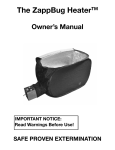
1
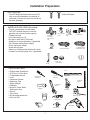
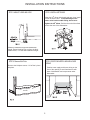
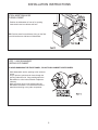
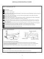
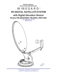
Installation Instructions
Built-In Dishwasher
Model(s):
DDW2405W DDW2405BL DW2406BLS
BEFORE YOU BEGIN: Read
STOP these instructions completely
and carefully.
IMPORTANT: Observe all governing codes
and ordinances.
Note to the Installer: Be sure to leave
these instructions for the consumer’s and local
inspectors use.
Note to Consumer: Keep these instructions
with your Owner’s Manual for future reference.
Skill Level: Installation of this dishwasher
requires basic mechanical and electrical skills.
Proper installation is the responsibility
of the installer. Product failure due to
improper installation is not covered
under the Dishwasher Warranty.
Completion Time 1 to 3 Hours.
IMPORTANT: The dishwasher MUST be installed to
allow for removal from the enclosure in the event
future service is required.
FOR YOUR SAFETY: Read and observe all
CAUTIONS and WARNINGS shown throughout
these instructions. While performing
installations described in this booklet, gloves,
safety glasses or goggles should be worn.
WARNING: To reduce the risk
of electrical shock, fire or
injury to persons, the installer
must ensure that the dishwasher is completely enclosed
at the time of installation
New installations require more time than
replacement installations.
READ CAREFULLY.
KEEP THESE
INSTRUCTIONS.
ver. 1 07.19.04
Installation Preparation
PARTS SUPPLIED:
2 Wood Screws
• Two #8 Phillips flat head wood screws 5/8”
long to secure dishwasher to underside of
countertop. (Screws can be found inside the
literature package)
MATERIALS YOU WILL NEED: (Not included)
• Ferrule, compression nut and elbow
(3/8” NPT external thread on one end,
opposite end sized to fit water supply)
• Thread seal tape
• cUL Listed wire nuts (3)
• Air gap for drain hose, if required
• Waste tee for house plumbing, if applicable
• 48” Electrical cable (power supply)
• Screw type hose clamps
• Hand shut-off valve
• Water line; Stainless steel braided flex hose
• Coupler for extending drain line, if applicable
90 Elbow,
Ferrule and
Compression
Nut
Hand Shut-Off
Valve
Wire Nuts (3)
Thread Seal
Tape
72” Stainless Steel
Braided Flex Hose
48” Electrical Cable
Waste Tee
Coupler
Screw Type
Hose Clamps
Air Gap
TOOLS YOU WILL NEED:
•
•
•
•
•
•
•
•
•
•
•
•
•
Phillips Head Screwdriver
5/16” and 1/4” Nut-driver
6” Adjustable Wrench
Level
Carpenters Square
Measuring Tape
Safety Glasses
Flashlight
Bucket to Catch Water
(flushing the line)
Gloves
Tube Cutter
Drill and appropriate bits
Hole Saw Set
Level
1/4” & 5/16”
Nut-driver
Phillips Head
Screwdriver
Carpenters
Square
6” Adjustable
Wrench
Flashlight
Tube Cutter
Measuring Tape
Safety Glasses
Bucket
Drill & Bits
Gloves
Hole Saw Set
1
INSTALLATION PREPARATION
PREPARE DISHWASHER ENCLOSURE
Floor must be
even with
room floor.
• The dishwasher must be installed so that the
drain hose is no more than 10 feet in length for
proper drainage.
• The dishwasher must be fully enclosed on the
top, side and back, and must not support any
part of the enclosure.
CLEARANCES: When
installed into a corner,
allow 2” min. clearance
between dishwasher and
adjacent cabinet, wall or
other appliances. Allow
25-5/8” min. clearance
from the front of the dishwasher for the door
opening. Fig. 2
Plumbing and
Electric Service
Must Enter
Shaded Area
• The rough cabinet opening must be at least
24” deep and to 24” wide. The opening
should be to 35” max height.
DRAIN REQUIREMENTS:
• Follow local codes and ordinances.
• Do not exceed 10 feet in distance to the drain.
• Do not connect drain lines from other devices
to the dishwasher drain hose.
• Dishwasher must be connected to waste line
with an air gap (not supplied) or 32” minimum
high drain loop, depending on local codes and
ordinances to prevent back flow into the dishwasher. Air gap must be used if waste tee or
disposer connection is less than 18” above the
floor to prevent siphoning.
DRAIN PREPARATION:
The type of drain installation depends on answers
to the following questions:
Do local codes or ordinances require installation
of an air gap?
Will waste tee or disposer connection be less
than 18” above the floor?
If the answer to ANY of the 2 questions above is
YES, METHOD 1 MUST BE USED. Otherwise
either Method 1 or Method 2 may be used.
Fig. 3 or Fig. 4
CAUTION:
An air gap MUST BE USED if the drain hose is
connected to waste tee or disposer lower than 18”
above the floor.
Failure to provide the proper drain connection
height with an air gap or 32” minimum high
drain loop will result in improper draining of
the dishwasher.
Method 1 Air Gap with Waste Tee or disposer
Method 2 High Drain with Waste
Tee or Disposer
Provide a method to attach drain hose to
underside of countertop.
2
CABINET PREPARATION:
• Drill a 1-1/2” dia. hole in the cabinet wall within the
shaded areas shown in Fig. 1 for drain hose
connection. The hole should be smooth with no
sharp edges.
INSTALLATION PREPARATION
PREPARE ELECTRICAL WIRING
WARNING:
FOR PERSONAL SAFETY:
Remove house fuse or open circuit
breaker before beginning installation.
Do not use an extension cord or adapter
plug with this appliance.
Electrical Requirements:
• This appliance must be supplied with 120V / 60 Hz.,
and connected to an individual properly grounded
branch circuit, protected by a 15 or 20 ampere circuit
breaker or time delay fuse.
• Wiring must be two wire with ground.
• If the electrical supply does not meet the above
requirements, call a licensed electrician before
proceeding.
Cabinet Preparation & Wire Routing:
• The wiring may enter the opening from either
side, rear or the floor within the shaded area.
• Cut a 1-1/2” max. dia. hole to admit the electrical
cable. The hole must be free of sharp edges. If
the cabinet wall is metal, the hole edge must be
covered with a bushing/grommet.
• Cable direct connections may pass through the
same hole as the drain hose and hot water line,
if convenient.
Grounding Instructions This appliance must be connected
to a grounded metal, permanent wiring system, or an
equipment grounding conductor must be run with the
circuit conductors and be connected to the equipment
grounding terminal or lead on the appliance.
WARNING:
Improper connection of the equipment
grounding conductor can result in a risk
of electric shock. Check with a qualified
electrician or service representative if
you are in doubt that the appliance is
properly grounded.
Electrical Connection to Dishwasher:
• The electrical connection is located on the right
front side of the dishwasher.
• The cable must be routed as shown in Fig. 5
Cable must extend a minimum of 24” from the
rear wall.
3
INSTALLATION INSTRUCTIONS
PREPARE HOT WATER LINE:
• The hot water line may enter from either side, rear or
floor within the shaded area shown in Fig. 6
• The line may pass through the same hole as the
electrical cable and drain hose. Or, cut an additional
1-1/2” dia. hole to accommodate the water line.
STOP
BEFORE YOU BEGIN
Locate and set aside the package containing the
2 Phillips Head Countertop Mounting Screws.
STEP 1 CHECK DOOR BALANCE
To check the door balance, hold the top of the dishwasher firmly.
WATER LINE CONNECTION:
• Turn off the water supply.
• Install a hand shut-off valve in an accessible location,
such as under the sink.
• The water connection is located on the left front side of
the dishwasher. Install the hot water inlet line, using a
braided flexible hose (available at most hardware
stores). Route the line as shown in Fig. 6 and extend it
forward at least 18” from the rear wall.
• Adjust water tank (heater) for 120 F to 150 F (49C to
65.5C) temperature.
• Flush water line to clean out debris.
• The hot water supply line pressure must be 20 ~ 120psi
CAUTION:
DO NOT OPEN THE DOOR UNTIL
YOU ARE READY TO INSTALL
THE DISHWASHER.
Opening the door will cause the dishwasher to tip forward.
If it is necessary to open the door, hold the top of the
dishwasher securely with one hand and hold the door with
the other hand.
4
• Open the door slowly, if the door drops when
released, increase spring tension. If the door
closes when released, decrease spring tension.
• Pull the spring adjustment pin out of the holes,
insert into the next highest or lowest hole and
test again.
• Adjust both door springs to the same tension.
• Continue moving the spring pin until the door
is balanced.
INSTALLATION INSTRUCTIONS
STEP 4 INSTALL 90o ELBOW
STEP 2 ADJUST LEVELING LEGS
Wrap the 90o elbow with thread seal tape, then install
it onto the water valve. To avoid damage to the
water valve bracket and/or fitting, do not overtighten the 90o elbow. Position the end of the elbow
to face the rear of the dishwasher.
Measure installation height and dishwasher
height. Extend leveling legs out from the dishwasher base, 1/4” less than installation height.
STEP 5 POSITION WATER LINE AND HOUSE
WIRING
STEP 3 Remove Kick Plate
Remove the kickplate screws. Lift off the 2 piece
kickplate.
• Position water supply and house wiring on the
floor of the opening to avoid interference with
base of dishwasher and components under
dishwasher.
2 Kickplate
Screws
5
INSTALLATION INSTRUCTIONS
STEP 6 INSERT DRAIN HOSE
THROUGH CABINET
• Position the dishwasher in front of he opening.
Insert drain hose into cabinet wall hole.
TIP: Position water line and house wiring on the floor
to avoid interference with base of dishwasher.
STEP 7 SLIDE DISHWASHER
PARTIALLY INTO CABINET
TO AVOID DAMAGING THE FRONT PANEL, DO NOT PUSH CABINET IN WITH KNEES.
• Slide dishwasher into the opening a few inches at
a time.
• As you proceed, pull the drain hose through the
opening under the sink. Stop pushing when the
dishwasher is a few inches forward of adjacent
cabinetry.
• Make sure drain hose is not kinked under the
dishwasher and there is no interference with the
waterline and wiring or any other component.
6
INSTALLATION INSTRUCTIONS
STEP 8 POSITION DISHWASHER UNDER COUNTERTOP
• Check to be sure that wires are secure under the
dishwasher and not pinched or in contact with
door springs or other dishwasher components.
TIP: Check tub insulation blanket.
It should be positioned so it is not bunched up or
interfering with door springs. Check by opening
and closing door.
• Push dishwasher into cabinet. The front corners
of the dishwasher door should be flush with
cabinet doors. Be careful not to dent front panel
with knees or damage countertop or cabinets
with dishwasher parts.
STEP 9 LEVEL DISHWASHER
IMPORTANT - Dishwasher must be
level for proper dish rack operation and
wash performance.
• Level the
dishwasher by
adjusting the four
leveling legs
individually.
• Place level on door
and rack track inside
the tub as shown to
check that the dishwasher is level.
TIP: Pull lower rack out, about halfway. Check
to be sure the rack does not roll forward or
back into dishwasher. If the rack rolls in either
direction, the dishwasher must be leveled
again.
• If the door hits the tub, the dishwasher is not
installed correctly. Adjust leveling legs to align
door to tub.
7
INSTALLATION INSTRUCTIONS
STEP 10
SECURE DISHWASHER
TO CABINET
STEP 11
CONNECT WATER
SUPPLY
Connect water supply line to 90o elbow.
The dishwasher must be secured to
the countertop.
• Position the dishwasher so that the tub flange
aligns with the front face of the cabinet frame.
Method 1 - Braided flex hose
• Connect the stainless steel braided flex hose
directly to the 90o elbow (as show in Figure 19)
IMPORTANT - Check to be sure the dishwasher
is centered in the opening and there is no interference with the adjacent cabinets when opening or
closing the door.
IMPORTANT -
Check to be sure that door spring
does not rub or contact the fill hose or water supply
line. Test by opening and closing the door. Re-route
the lines if a rubbing noise or interference occurs.
• Fasten the dishwasher to the underside of the
countertop with the 2 Phillips screws provided.
IMPORTANT - Drive screws straight and flush.
Protruding screw heads will scratch the top of the
control panel and can interfere with door
opening/closing.
8
INSTALLATION INSTRUCTIONS
STEP 12 CONNECT DRAIN LINE
DRAIN LINE INSTALLATION
FOLLOW ALL LOCAL CODES
AND ORDINANCES
• Connect drain line to air gap, waste tee or disposer
using either of the previously determined method.
The drain hose molded end will fit 5/8”, 3/4” or 1”
diameter connections on the air gap, waste tee or
disposer. Cut the marked line as required for your
installation.
Method 1 - Air gap with waste tee or disposer
Method 2 - High drain loop with waste tee or disposer
• If a longer drain hose is required, add up to 42”
length for a total of 10ft. to the factory installed
hose. Use 5/8” or 7/8” inside diameter hose and
a coupler to connect two hose ends. Secure the
connection with hose clamps.
• Secure the drain hose to the air gap, waste
tee or disposer with clamps.
NOTE: TOTAL DRAIN HOSE LENGTH MUST NOT EXCEED
10 FEET FOR PROPER DRAIN OPERATION.
IMPORTANT When connecting the drain line to
the disposer, check to be sure that
the drain plug has been removed.
DISHWASHER WILL NOT DRAIN IF
PLUG IS LEFT IN PLACE.
TIP: Avoid unnecessary service call charges. Always
be sure disposer drain plug has been removed before
attaching dishwasher drain hose to dispenser.
9
INSTALLATION INSTRUCTIONS
STEP 13 CONNECT POWER SUPPLY
STEP 14 PRE-TEST CHECK LIST
Review this list after installing your dishwasher
to avoid charges for a service call that is not
covered by your warranty.
• Remove junction box Cover “ A “.
• Locate the three dishwasher wires, (white, black and
green) with stripped ends. Insert dishwasher wires
through the small hole in the junction Box “ B “.
• Secure house wiring to the bottom of the junction box
with a strain relief “ C “.
• Use wire nuts to connect incoming ground to green,
white to white and black to black “ D “.
• Replace junction box cover “ E “, check to be sure that
wires are not pinched under the cover.
Check to be sure Power is OFF.
Open door and remove all foam and paper
packaging.
Locate the Owners manual in the literature
package.
Read the Owners manual for operating instructions.
Check door opening and closing. If door does
not open and close freely or tends to fall,
check spring adjustments. See Step 1.
Check to be sure that wiring is secure under
the dishwasher, not pinched or in contact with
door springs or other components. See Step
9.
Check door alignment with tub. If door hits
tub, level dishwasher. See Step 10.
Pull lower rack out, about halfway. Check to
be sure it does not roll backward or forward on
to the door. If the rack moves, adjust leveling
legs. See Step 10.
Check door alignment with cabinet. If door hits
cabinet, reposition or re-level dishwasher. See
Step 10.
Verify water supply and drain lines are not
kinked or in contact with other components.
Contact with motor or dishwasher frame could
cause noise. See Step 8.
Turn on the sink hot water faucet and verify
water temperature. Incoming water temperature must be between 49oC (120oF) and
65.5oC (150oF). A minimum of 49oC temperature is required for best wash performance.
See “ Prepare Hot Water Line”, page 4.
WARNING
If house wiring is not 2-wire with
ground, a ground must be provided
by installer. When house wiring is
aluminum, be sure to use UL listed
antioxidant compound and aluminum
to copper connectors.
Add two quarts of water to the bottom of the
dishwasher to lubricate the pump seal.
Turn on water supply. Check for leaks. Tighten
connections if needed.
Remove protective film if present from the control panel and door.
10
INSTALLATION INSTRUCTIONS
STEP 15 DISHWASHER WET TEST
Turn on power.
Make sure door is closed.
Select “Normal” wash program.
Check to be sure that water enters the dishwasher. If water does not enter the dishwasher, check to be sure that
water and power are turned on.
Check for leaks under the dishwasher. If a leak is found, turn power supply off, then tighten connections.
Restore power after leak is corrected.
Check for leaks around the door. A leak around the door could be caused by the door rubbing or hitting again
adjacent cabinetry. Reposition the dishwasher if necessary. See Step 9.
The dishwasher will drain and turn off about 5 to 7 minutes after the first fill. Check drain lines. If leaks are
found, turn power off at the breaker and correct plumbing as necessary, Restore power after corrections are
made. See Step 12.
Open dishwasher door and make sure most of the water has drained. If not, check that the disposer plug has
been removed and/or air gap is not plugged. See Step 13. Also check drain line for kinking.
Run the dishwasher through another fill and drain cycle. Check for leaks and correct if required.
At the end of drain cycle; open door and turn off power.
STEP 16 REPLACE KICKPLATE
Anterior Kickplate
2-Screws
kplate
2- Piece Kic
Adhesive Tape
Adjustable Kickplate
Adjust Up or Down
• Tear down the adhesive tape on the kickplate.
• Place both kick plate pieces against the kickplate bracket, let the two hooks of the anterior kickplate
align with the slot of the adjustable kickplate, then the two hooks align the short slot of the kickplate bracket,
let the hook be fastened to the kickplate.
• Install 2 kickplate screws to fasten anterior kickplate. Allow the adjustable kickplate to touch the floor.
`
STEP 17 LITERATURE
Be sure to leave complete literature package and installation instructions with consumer.
Continuing research results in steady improvement. Therefore, this information and these specifications are subject to change without notice.
11