1
Approved
for public release; distribution
is
unlimited
An
Application of Virtual Prototyping
to the Flight Test and Evaluation of an Unmanned Air Vehicle
by
Mark T. Lagier
Lieutenant Commander United
B.S.,
States
Navy
Oregon State University, 1983
Submitted
in partial fulfillment of the
requirements for the degree of
MASTER OF SCIENCE
IN
AERONAUTICAL ENGINEERING
from the
NAVAL POSTGRADUATE SCHOOL
March
,
1994
Daniel J. CoHins, Chairman
Department of Aeronautics and Astronautics
u
UNCLASSIFIED
:URITY CLASSIFICATION OF THIS PAGE
REPORT DOCUMENTATION PAGE
REPORT SECURITY CLASSIFICATION
.
RESTRICTIVE MARKINGS
lb.
UNCLASSIFIED
SECURITY CLASSIFICATION AUTHORITY
.
3.
DISTRIBUTION/AVAILABILITY OF REPORT
Approved
DECLASSIFICATION/DOWNGRADING SCHEDULE
).
for public release;
distribution
PERFORMING ORGANIZATION REPORT NUMBER(S)
NAME OF PERFORMING ORGANIZATION
.
6b.
5.
OFFICE
(if
Monterey,
CA
ADDRESS
NAME OF MONITORING ORGANIZATION
7b.
Naval Postgraduate School
ADDRESS (City, State, and ZIP Code)
93943
Monterey,
8b.
ORGANIZATION
.
7a.
EC
NAME OF FUNDING/SPONSORING
.
(City, State,
OFFICE
(if
unlimited.
applicable)
Naval Postgraduate School
ADDRESS (City, State, and ZIP Code)
.
SYMBOL
is
MONITORING ORGANIZATION REPORT NUMBER(S)
SYMBOL
9.
CA
93943
PROCUREMENT INSTRUMENT IDENTIFICATION NUMBER
applicable)
SOURCE OF FUNDING NUMBERS
PROJECT
TASK
ELEMENT NO.
NO.
NO.
and ZIP Code)
10.
WORK
PROGRAM
TITLE (Include Secunty
[.
le Flight Test
^^ AppHcatioU of Virtual
of an Unmanned Air Vehicle
Classification)
and Evaluation
ur
ACCESSK
Prototyping tO
PERSONAL AUTHOR(S)
!.
Lagier,
TYPE OF REPORT
Ja.
13b.
FROM
Master's Thesis
SUPPLEMENTARY NOTATION
>.
fficial
policy or position of the
GROUP
FIELD
07/91
TO
The views expressed
COSATI CODES
r.
14.
12/93
ABSTRACT
if
15.
PAGE COUNT
those of the author and do not reflect the
Department of Defense or the United States Government.
18. SUBJECT TERMS (Continue on reverse if necessary and identify
SUB-GROUP
(Continue on reverse
DATE OF REPORT (Year, Month, Day)
March 1994
in this thesis are
by block number)
Dynamic Modelling, Controller D
Dynamics Testing, Over the Horizon Piloting
Virtual Prototyping, Visual Feedback,
Testing, Flight
3.
Mark T.
TIME COVERED
necessary and identify by block number)
effort to design, test and fly an Unmanned Air v(
Simulink or Matrixx provide powerful design tools with limited graphical oi
lat require an intimate knowledge of the underlying dynamic structure. For comprehension, Virtual Prototyping
\ intuative approach toward understanding the dynamic performance of the model. When the aircraft is flown \
sual range of the ground station, a Virtual Prototype display provides the pilot on the ground a close-up vi
rcraft response. When the aircraft operates over the horizon, a Virtual Prototype display becomes the only visuj
2tween the pilot and the aircraft. An application of a Virtual Prototype software is presented here with a direct
implementing the results in the UAV project currently underway at The Naval Postgraduate school.
Virtual Prototyping
is
an integral part of the ongoing
urrent analytical software such as
;
)
DISTRIBUTION/AVAILABILITY OF ABSTRACT
D.
X]
2a.
>
21.
UNCLASSIFIED/UNLIMITED QsAMEASRPT.
NAME OF RESPONSIBLE INDIVIDUAL
Isaac I. Kaminer
FORM
1473, 84
MAR
83
APR
ABSTRACT SECURITY CLASSIFICATION
D DTIC USERS
UNCLASSIFIED
22b.
TELEPHONE (Include Area
(408) 656-2972
edition may be used until exhausted
All other editions are obsolete
Code)
22c.
OFFICE SYMBOL
AA/KA
SECURITY CLASSIFICATION OF THI
UNCLASSIFIED
ABSTRACT
Virtual Prototyping
and
fly
is
an integral paxt of the ongoing
effort to design, test
an Unmanned Air Vehicle. Current analytical software such as SiMULINK or
MatriXx
provide powerful design tools with limited graphical output, that require
an intimate knowledge of the underlying dynamic structure.
For comprehension,
Virtual Prototyping allows an intuitive approach toward understanding the dynamic
performance of the model.
When
the aircraft
is
flown within visual range of the
ground station, a Virtual Prototype display provides the
up view of
aircraft response.
When
pilot
on the ground a
the aircraft operates over the horizon, a Virtual
Prototype display becomes the only visual link between the pilot and the
An
application of a Virtual Prototype software
to implementing the results in the
close-
UAV
is
presented here with a direct view
project currently
Postgraduate School.
m
aircraft.
underway
at the
Naval
e.l
TABLE OF CONTENTS
I.
II.
INTRODUCTION
A.
UAV PROJECT
B.
DESIGNER'S
1
WORKBENCH
GRAPHICS EDITOR
3
6
A.
GETTING STARTED
6
B.
CONFIGURING THE DWB WORKSPACE
8
C.
CREATING A DATABASE
1.
D.
E.
IIL
1
DWB
10
Structure
11
a.
Basic Elements
11
b.
Manuevering inside the Structure
13
BUILDING A 3-D IMAGE
—
1.
Example
2.
SUMMARY
15
Using the 3-D tools
18
23
ENHANCING THE MODEL
24
1.
Color
24
2.
Face Reversal
26
3.
Mirror
27
ADVANCED MODELLING
28
A.
CLIP REGIONS
28
B.
PERSPECTIVE REGIONS
31
1.
Utilizing the Perspective Region
35
a.
Scale
36
b.
Aspect Ratio
37
iv
DUDLEY KNOX LIBRARY
SCHOOL
NAVAL POSTGRADUATE
MONTEREY CA 93943-5101
LINK EDITOR
IV.
A.
B.
_,
V.
VL
39
VARIABLES
40
1.
Internal Variables
40
2.
External Variables
40
OBJECT LINKS
41
1.
Translation and Coordinate Links
43
2.
Rotation Links
48
3.
Some
50
Final Notes on Object Linking
C.
EYE POINT LINKS
D.
PAGE LINKS AND LINKING
COMMUNICATION
52
IN
THE PERSPECTIVE REGION
^
54
55
A.
.VARS FILE
56
B.
DATA FILES
58
C.
SHARED MEMORY AND ETHERNET CONNECTIONS ....
60
CONCLUSIONS AND RECOMMENDATIONS
61
A.
CONCLUSIONS
61
B.
RECOMMENDATIONS
61
APPENDIX A
APPENDIX B
:
:
LIST
of
PROJECT FILES
DATA CONVERSION PROGRAM
63
IN "C"
65
REFERENCES
68
INITIAL DISTRIBUTION LIST
69
LIST OF TABLES
5.1
.VARS FILE
STRUCTURE
57
VI
LIST OF FIGURES
1.1
AROD
2
1.2
Archytas
3
2.1
DWB
8
2.2
Coordinate Input
3.1
Clip Region Implemented on an a Attitude
4.1
Internal Variables
41
4.2
External Variables in the .vars File
42
4.3
Link Create/Edit Dialogue Box
44
4.4
Coordinate Link Edit Box
46
4.5
Mapping Function Editor
47
5.1
The Conmi Editor
56
5.2
The
.vars File
57
5.3
The
.data File
59
Workspace Environment
Window
18
Vll
Gyro
32
ACKNO WLED GMENT
I
would
like to express
my appreciation to Professor
and professional counsel without which
also like to
I
Isjiac
thank Mr. Glen Raudins of Corphaeus Software,
Matthew Koebbe
of the
his advice
could not have completed this work.
I
would
Inc. for his patience
input during the development phase of this project. Finally,
Mr.
Kaminer for
I
would
like to
Computer Science Center Visualization Lab
and
thank
staff for
the countless hours he devoted to helping develop a permanent video record of the
project.
Vlll
I.
A.
INTRODUCTION
UAV PROJECT
The
UAV
project currently in progress at the Naval Postgraduate School has
Fixed wing research, and
VTOL
development. The fixed wing
two major
thrusts:
research
being conducted on a small aircraft called BLUEBIRD. This
is
piloted vehicle with a wingspan of 12
20
lbs.
This aircraft
is
ft,
is
a remotely
and a pay load capacity of approximately
currently being flown at the Naval Postgraduate School, and
provides a test bed for commimications equipment and as a stable test platform for
experimental controllers. There are a number of
on the
aircraft to refine the
flight test projects
dynamic model of the
aircraft
being conducted
being used in the controller
and communications equipment design.
The second major
research area,
VTOL
developm.ent,
is
being conducted on
a platform originally designed by Sandia National Laboratory for the Marine Corps
named
AROD
(see Figure 1.1).
The Aeronautics and Astronautics Department subsequently acquired a number
of these aircraft
aircraft that
was designed to take
copter in hover.
AROD
from the defunct program. The
It
was to remain
and maneuver principally
off vertically,
vertical for the entire flight,
requirements and drag penalties induced by this
low range capabilities.
flight
The program underway
consists of attaching wings to
was essentially a ducted fan
AROD
mode
at the
derivative
is
as such, the
resulted in unacceptably
and designing a controller that
called Archytas. Figure 1.2
is
an
power
Naval Postgraduate School
aircraft to take off vertically, transition to horizontal flight,
AROD
and
as a heli-
and land
artist's
will allow the
vertically.
This
conception of Archytas.
Figure
One
AROD
of the projected missions of Archytas
horizon capabilities to the battlefield
or at the
1.1:
most requires the use
is
commander
to provide
unmanned
in a package that is
of a light utility vehicle or pickup.
the projected Archytas mission include an autonomous
GPS
man
over-the-
portable
Other features of
aided trajectory guid-
ance system, and a future autoland system. There are also provisions for reverting to
piloted flight,
and
it
was
this requirement along
with the over-the horizon mission that
drove the need to develop a virtual protot)q)e system. The computational/analytical
software existing in the department consists primarily of Matlab and
their associated "graphics" modules, Simulink
and Systembuild. Both of these
ware packages provide extremely powerful methods
lyzing
dynamic nonlinear
controllers.
They
MATRIXx with
for designing, testing
soft-
and ana-
are extremely limited, however, in their
ability to provide a feedback display suitable for
conducting piloted
flights of
the
Figure
UAV
project aircraft.
At
1.2:
Archytas
best, the simulations
run in these software environments
can provide a 3-D line plot of the time history of the trajectory, along with a 1-D
running plot of selected outputs.
to
It
would border on the impossible to expect a
be able to detect and respond to fluctuations
pilot
in the aircraft attitude utilizing these
types of displays.
B.
DESIGNER'S
To
fill
WORKBENCH
this shortcoming, the
Department of Aeronautics and Astronautics pur-
chased a software package called Designer's Workbench
(DWB).
DWB
is
a 3-D inter-
graphics program that allows the user to create unique situationally specific models,
construct associated cockpit instrumentation and
HUD
displays,
databases with information derived from an outside source.
It
and animate these
provides a
means
of
supplying instantaneous visual feedback to the pilot, and has become a major contributor to the design
The
and testing of a trajectory controller
goal of this thesis was to integrate
as Simulink, currently
into three
major
for Bluebird.
DWB with other simulation tools,
used at the Avionics Lab. To that end, this work
such
broken
is
categories:
• Creating a database
• Linking
•
Communication
Throughout
document, every attempt has been made to provide
this
ples of the tasks required to provide a fully functionally
that the reader
is
not limited to one application.
The
this
document are the
have been created in conjunction with
this project,
exam-
animation in such a way
software
is
versatile
that applications could be expanded well outside of the referenced
Attached as Appendices to
specific
following:
a
list
UAV
of the
enough
projects.
files
that
a description of some of the more
complicated links that went into creating a working simulation, and a copy of the
C
language program used to convert the data saved from Matlab/Simulink simula-
tions to a useable format. In an effort to convey accurately, with the least
confusion, each step required to create, link,
definitions
amoimt
of
and animate a database, the following
have been used:
•
DWB... Designer's Workbench integrated software package.
•
Workspace
Panel...
create, edit,
• Workspace...
The area above the drawing window
that contains
and movement icons necessary to manipulate a database.
The drawing environment.
all
of the
• Structure Chart...
structure. It
of the
is
The iconized "wiring diagram"
invoked by toggling the icon in the extreme upper right comer
Workspace Panel
• Click...
The
of the hierarchy of the database
[Ref. 2, p. 3-23].
act of selecting an icon in a Graphical User Interface environment.
Also select, choose, and open.
• Window... In an
open editor
(e.g.
Mapping, Link,
etc.),
the area specified for
entering or viewing values.
This thesis was not meant to be a replacement for the reference and user's
manuals supplied by the manufacturer.
The appUcations
discussed in this thesis
assume a fimdamental understanding of the concepts and mechanics contained
1]
[Ref.
2]
[Ref.
3]
[Ref.
4].
The major
thrust of this
in [Ref.
work was to expand on the
mechanics approach of the manufacturer's documentation to allow
for greater user
applications.
Finally, as with
to successfully
any attempt to portray
I
procedures necessary
implement a software package, there are times when the vocabulary
available for expressing a particular action
possible,
in writing the
becomes exhausted. To the greatest extent
have attempted to vary the use of any given word. One such situation that
springs inomediately to mind,
is
the act of selecting a button or icon in a Graphical
User Interface environment. After
grows very short.
Select, click,
and choose, the
list
of available verbs
II.
The
GRAPHICS EDITOR
software utilized to create a Virtual Prototype world for the
UAV project is
an interactive graphics program called Designers Workbench developed and marketed
by Coryphaeus Software
ment
at this
time
is
of Los Gatos,
composed
of
CA. The software
design, background construction,
subgroup
ically
is
it
exists in the depart-
two fundamental subgroups. The
modelling editor, or data base/link editor. This
model
as
the Rimtime Module. This
is
of these
the environment in which
and link editing
is
first
is
all
is
the
of the
conducted. The second
an optimizing program that
will
automat-
execute a previously constructed simulation without the need for invoking the
editor.
GETTING STARTED
A.
Designer's
Workbench has been
installed
on Indigo3.aa.nps.navy.mil
in the In-
digo lab administered by the Department of Aeronautics and Astronautics.
installation procedures differ shghtly
the working
files
from those
listed in the setup
manual
The
in that
have been installed in /usr/local/bin as opposed to the reconmiended
/usr/cs/hin. Aside from defining paths differently, this will have no effect on the useability of
DWB.
Three steps need to be done prior to running
DWB
on an indigo
attached to the aero server.
•
The Bitmaps contained
in the
working
files
of
DWB
(/usr/local/dwh2) must be
linked to the personal account of the user. Let's say the user's account
name
was Hacker, and Hacker's directory path was /d4/hacker. To link the bitmaps,
at the
command prompt
type:
In -s
•
The environment must be
server
/d^/hacker/BITMAPS
/usr/local/dwh2/BITMAPS
and working
setenv
CSL_DIR
2.
setenv
CS_DIR
These commands
tell
executable
The commands
files.
1.
set for the
file
to be able to find the license
to accomplish this axe:
/usr/local/lic
/usr/local
the operating system that the license information for
DWB
can be foimd in the directory user/local/lic, and that the information needed to
execute
DWB
can be found in the directory /user/local. This can be accomplished
either at the beginning of each log-on session, or can
user.
While editing the
copy of an .cshrc
The
is
is
.cshrc
shown
last step that
running [Ref.
in
file,
set in the .cshrc file of the
DWB should be added to the users path. A sample
Appendix A.
needs to be accomplished
1, p.3-13].
be
To
is
verify this, type the
to ensure that the license server
command:
/usr/local/hin/CSL.server&
If
the license server
is
running.
start
it
(the
If for
&
is
already running, a response will
some
reason, the server
is
come back
stating that a server
not up and running, this
command
will
sign will allow the server to run in the background).
Once these
steps have been executed (normally only needed one time),
command prompt,
is
ready to run. At the
it
to initialize and for the graphical editing environment to appear.
type the comraiand "dwb2" and wait for
The remaining
sections of this chapter cover the skills required to successfully build a useable
and/or database.
DWB
model
CONFIGURING THE DWB WORKSPACE
B.
The
y
tilt
I (ii
foes
initial screen
r)rc<f>hi<;s
Stntohtre
the user faces
ScUm;!
t'l-oix'rtic?
when
I
DWB
Misc
'lit
p.1rf(U tiOffc
links
jMok
iiOt
is
shown
in Figure 2.1.
Aniin,jti<4)
K
qrtd olivet
h
^,
|ppEj:i4^i|™r^
Ho (tie tea<teU
comes
'
iLl^
jjM_V—
,ot?
xicntatK-tv:^
cycpoint;:
;
,
'%i;i;";4'/,/'
ff
,y","
oyf^//f^^^ ^///f^y/^f/ y^/f^
<*
,
,
'"
'
'"yy ^^
'^^ ^^
/'/
^
'"
/',y' y"' '"''/' 4",,
',^
'
^^^^^^,,,^ ^y/^^^^,' ^f/j /yyyy^^y^^-'^^^^^^A
/
.
;'>y/yiyf/yy'y,/,
Figure
To open an
'
',
'yjy/,^,y^^
2.1:
first
„„
"!-/
, ';^;';;'^^ ' '
^^y '^y^y
^y^y^^y
iyy
^
y
'
'
^
^^ ^
J
^
'/
;"'y, ',;, %
y^ v^^y^^yyyy^yjy
/^iiy/y^^^^^
''y,y^''^
,f, ''">,/' i'^''y^,;""'/
y ^y
^^,
y
DWB Workspace Environment
existing database, the pull
graphical interface identical to
start
,
^ ^f 'y^
Windows
down
file
menu can be used with
or Macintosh products [Ref.
2, p. 2-2].
the
To
a new data base, there are several additional tasks that need to be accomplished
in order to
maximize the usefulness of our model.
«
r
Decide what scale the database
Given the relatively small
to be
is
size of the
drawn
to.
two primary
aircraft associated
with the
UAV project, drawing an accurately sized version of one of these to import
a
into
a loss of perspective because you are
full scale airfield will result in either
too close to the aircraft, or a loss of detail because you are far enough away to
As a general
see the field but lose the detail of the aircraft.
rule, the largest
item in the database should drive the scale of the remaining items.
especially important
when
constructing a cockpit or
unnatural to build an airspeed gauge that
ft.
in diameter, but
it
will greatly
Once you have decided what the
(for
is,
HUD
display. It
This
is
may seem
according to your grid
size,
300
enhance the your ability to use the display.
largest
the simulations currently running in
item in your database
DWB
this is
by
is
going to be
far the airfield), the
workspace needs to be configured as follows:
1.
With the
edit
original grid
on the screen, and nothing selected, go to the
pulldown menu and
select
modify attributes.
A
grid attributes edi-
tor will appear that allows the user to select the units for the grid size
(i.e.
ft,cm,in,etc.).
2.
Click the grid attributes icon on the workspace panel (the one with the
question
mark on
it
inmiediately to the right of the set/pick buttons). In
this dialogue box, the size of the grid square
the spacing of the grid division lines [Ref.
A Word of Caution:
atively large,
it is
If
2, p. 3- 13].
the grid you are planning to create
a good idea to
a manageable number.
can be changed, as well as
When
first
DWB
is rel-
change the grid spacing to
initializes,
the grid defaults
to a 1 meter square, with a spacing of 8.33 centimeters.
example, the
ft
size of the grid
If,
for
you were going to create was 1500
square, and you changed the grid size without
first
changing
the spacing, the program would attempt to create a 1500
with major grid divisions spaced 0.0027
ft
ft
grid
apart and with 5 mi-
nor subdivisions between each of these. The result will be the
computer trying to create
At best
2.74 x 10®
separate lines
this process will take several minutes,
computer
in each direction.
and
at worst the
will lock up.
• Set the preferences.
Under the
pull
down menu
Misc., the third entry will be preferences.
Opening
the preferences editor will present the user with four settable options.
the immediate concerns to us
is
the auto-write option.
pulldown menu in the preferences
editor, select the
autowrite. This feature determines
how many
need to occur before
DWB
number
saved
does an auto-backup on the
be saved
file
Set the autosave
file.
in. It is also
in the specified directory
(.XXX being either .dwb or .Ink
C.
page option, and choose
possible to change
of modifications that take place between autobackups.
files will
of
the preferences
revisions to a drawing or link
write path to the directory you wiU be working
the
Open
One
The
auto-
under the exetension .xxx.tmp
files.)
CREATING A DATABASE
Now
that
we have
configured our workspace,
construction of a database. Whether
vehicle
(i.e.
it is
an
we
are in a position to begin
airport, airplane or
tank), the graphics principles remain the same.
10
some type
Make
of groimd
sure you have a
copy of the
listed references available as
the tools available to us in
1.
DWB
DWB
Structure
Before
we begin
examine how
DWB
following
Header
•
Group
of using
to build a model,
will structure the database,
how
this structure to suit
we need
to
this structuring will affect
our needs [Ref.
first
our
2, p. 3-24].
Basic Elements
There are four basic building blocks of the
•
example
the process of building a dynamic model,
model, and how we can modify
a.
we go through the
DWB
structure:
• Face
• Vertex
If this is
your
first
time using
DWB
(i.e.
you have no existing files), go to the directory
/usr/local/dwb2 and open one of the .dwb
files
existing there. Toggle the structure
icon (the top one in the upper right corner of the workspace panel) to switch to the
structure chart. In this window, you will see at the top of the structure, a white box
with the filename and path in
the
file.
it.
This
is
the header box, and
Click on the header box, and notice that
header become highlighted by dashed
will find that clicking
lines.
K you
all
it is
used to identify
of the boxes attached to the
toggle back to the workspace,
on the header has selected the entire database.
structure chart, and click somewhere in the
empty paxt
header. Observe that attached to the header are a
number preceded by a
y,
of the
number
window
Go back
you
to the
to deselect the
of red boxes with either a
or a name. These are the groups.
They can be considered
chapters in the database structure. Once again, cUck on one of the red group boxes,
11
and you
will notice that all the items in that
that they have been selected in the database.
an item
will also select all of the structure
group become highlighted to indicate
As you can
a group or
see, selecting
items attached to
At
it.
this point, taJ<e
note of the small white square in the upper right corner of some of the group boxes.
This square indicates that the group has been "compressed", and that there are more
structure items hidden below that group. These structure items with attached blocks
are called the parent blocks, while the attached items axe
the middle
mouse button,
click
known
on a red parent box, and you
or compress depending on what state
extremely useful with large databases;
was
it
it
in before
will see it either
below.
as a
"child" group
It is
way
is
expanded
it
alleviates the necessity of
may have more
With
expand
you started. This feature
through every structure item to find one that you want. You
when a
as children.
may
having to page
also notice that
children groups attached to
perfectly acceptable to "nest" groups like this,
and
is
is
highly
it
recommended
of logically organizing a database.
At some
point, the nested groups will end,
and attached to these
innermost child groups you will find a number of multicolored boxes labelled with
a figure beginning with
box corresponds to the
when
it
p.
These are the faces
(or polygons),
and the
color of the face in the database. This feature
is
convenient
comes time to group items; you don't necessarily have to worry about finding
a collection of faces based on shape, location or the alpha-numeric
object,
color of the
if
you know what color
it is.
Note that
indicator square in the upper right comer.
If
eax:h face also
identifier of
an
has a "compressed"
you expand the
face,
you
will find
similarly colored blocks with an identifier corresponding to the face block followed
by a
colon,
and
several
more numbers. These are the vertex
smallest structure item that exists in
DWB.
12
addresses. This
is
the
A
Point of Technique. Take the time
cis
you proceed with building
a database to return occcisionally to the structure chart, and reorganize the structure.
It is
recommended
highly
runways,
etc,
be established
name that
meaningful
that individual items such as gauges, airplanes, buildings,
in their
will help
own group and
that you give each such group a
you keep track of where you are in the database. While
not critical that this be done during the building phase,
it is
it
will significantly
reduce
the time and frustration associated with creating Unks and running an animation.
Manuevering inside the Structure
b.
Now
them? Close the
that
file
we know what the
that
we opened
we do with
building blocks axe, what do
to look at the structure,
and
staxt a
new
file.
Don't worry about setting the environment or grid properties, as we will only be here
for
a moment. Without doing anything
find a header called
new with a group
else,
go to the structure chart. Here you will
labelled gl attached to
workspace, and put a few objects on the screen.
or circles,
and when you have created two or
Notice that
well
and good
what
if
of the items
all
if
Go back
Make something simple
three, toggle
like
to the
squares
back to the structure.
you created have been added to the group
gl.
This
is all
you wanted everything you created to be paxt of one big group, but
you wanted the next item you created to be separate, or you want to move
one of the items already created to a separate group?
if
it.
you were creating
flight
An example
instruments for an instrument panel.
It
of this
would be
would be a good
idea to have each of the instruments in a separate group to facilitate linking.
Chapter IV
for
more
details
(See
about linking.)
To put the next item you
create into a separate grouping, you need
to change the parent. In the upper left corner of the workspace panel,
you wiU see
a window labeled parent, and in that window will be the group gl. Toggling back to
13
the structure chaxt, select the header, then go up and click on the
in
The paxent
it.
label gl will change to new. Toggle back to the workspace, create
another square or
circle,
new group has been
and go back to the structure
new
chart.
You
will notice that
in the structure. It allows
new
group.
The Parent box
if
is
you to selectively choose what you want
objects to be attached to rather than forcing you to find and
the fact. But what
a
created (probably labeled g2 and attached to the header), and
the item you just created has been attached to this
Uke a bookmark
window with gl
move them
after
you have already created something in one group that you want
to attach to another group? This can be done in one of two ways. Let's say that one
g2 and make
of the items in the group gl actually belongs in group g2. Select group
it
the parent, then select the item you want to move.
menu,
select the entry Attach.
The other way
to
move items
You
to the Structure pulldown
will see the selected face
in the structure
is
on the item you want to move and holding the
to the group
Go
move
to the group g2.
the drag-and-drop method. Clicking
left
mouse button down, drag the
g2 and when the red g2 box haa a white border around
mouse button. The
selected face will
move
go of the
to the group g2.
As you proceed with the building
of your model, the easiest
keeping track of where you are and where your objects are,
logical sorting. For instance, the fuselage
it, let
face
is
way
of
to groifp your items by
and empennage could be
in a
group
titled
aircraft body, the
wings could be a separate group with subgroups of the leading
Naming
the groups as you go will greatly facilitate editing and linking your
edge,etc.
model.
DWB will allow just about anything in the way of names; there
on how many
letters or
numbers you may
use,
is
no
restriction
and the software wiU recognize white
space so you can label the groups intelligently as opposed to the standard Unix or
DOS
conventions of abbreviating to the point of absurdity. For example, a particular
group might be labeled:
14
Instantaneous Vertical Speed Indicator
and would read just
can use the
like that in the structure chart.
Rename menu
To rename a group
option in the Structure pulldown menu, or a quicker
letter "j".
way
box you want to rename,
woiild be to use the "hot key". This entails selecting the
and then typing the
or face, you
The standard dialogue box
will appear,
and you can
proceed as before.
As a
final point in this discussion
open the Structure pulldown menu. You
to back", "send to back one",
draws a picture,
it
must
drawn. Unlike the real world, where
DWB
up and
structure, go
will see options like "bring to front",
"send
When
DWB
and "bring to
prioritize in
about
front one" [Ref. 3, p.3-16l.
some way the order
it is
obvious
fairly
blocked by something else in your line of sight,
DWB
if
which the structure
is
your view of an object
is
in
has no
way
of
knowing which
item should be placed in front of the other, especially when you begin rotating the
picture.
Selecting the option Bring to Front will cause
object last so that
it is
database
180''.
be drawn
is
rotated
first,
DWB
to always
draw that
always on top, and consequently always visible, even
if
the
Conversely, selecting send to the back will cause the item to
and therefore on the bottom and covered by everything between the
object and the eyepoint.
As we
will discover later in the chapter,
of graphics does not fa<:ilitate drawing true
3-D
the current level
perspective pictures, so along with
backface removal and mirroring, changing the order in which things appear in your
structure can greatly affect
D.
how
BUILDING A 3-D IMAGE
The most important thing
it
the finished product looks.
operates essentially in a
point,
DWB
will
to realize about the
DWB
2-D environment. This means
attempt to default that point to where
15
it
graphics editor,
that
when you
thinks
it
is
that
create a
belongs on the
grid.
you attempt to create a point
If
structure,
be,
DWB
and while
it
will maice
may
in free spa<:e
a best guess at what
it
by forcing
[Ref,
does have a limited capacity for creating "preformed"
3-D
first priority
the environment to create a
methods of manuevering the
• Rotate the grid to
for
anything except
how
to manipulate
grid orientation to create the third dimension.
an orthogonal plane.
X-Y
plane.
The
orienta-
on the lower middle portion of the workspace panel allows the user
other things, reorient the grid to any of the three principle planes.
Simply rotating the grid to one of these planes
structure at the
precisely create
is
DWB
workspace. Discussed next are some
the workspace starts up, the grid defaults to the
among
will
structures, the nature of
then should be to discover
3-D image in a 2-D
While
2, p. 3-15].
aerodynamic modeUing usually prohibits the use of these items
fundamental subsets. Our
it
rotate the structure that the free space point
it
to,
the grid
thinks the third dimension should
ended up nowhere near where you intended to put
tion button
off of
look satisfactory from the current viewing perspective,
become immediately apparent when you
When
it
also a quick
(first) initial
will leave the center of the grid
origin of the picture. This will allow the user to
and orient structures that contain orthogonal members. This
way
to check the scale of the
model
in different planes.
• Orient the grid to a particular face.
Say for instance, that you have created a cylinder with ten
these sides, you wish to place the words U.S.
accurate
way
to accomplish this
is
NAVY. The
On
sides.
easiest
to align the grid to the face that
one of
and most
you wish to
place the text on. Select the orientation button on the workspace panel, choose
the face option, and a dialogue box will appear asking the user to select a face.
Click the
mouse on the
face you wish to place the text on, select
16
OK on
the
dialogue box, and the grid
is
now attached
origin located at the centroid of the face.
you
may
origin
you
to the face
Once the
selected, with the grid
grid has been reoriented,
change the orientation to a principle plane and
remain
at the centroid of the face selected.
still
have the grid
This can be an extremely
empennage
useful feature
when
an
Note that the same procedures apply to orienting the grid to a
aircraft).
particular vertex.
constructing complex databases (such as the
The
grid will be oriented perpendicular to the
vertex, but the orientation
back to the
initial origin,
may
then be changed as desired. To
of
normal of the
move
the grid
simply select origin imder the grid orientation icon.
• Input the coordinates directly.
In the extreme upper right
labeled x
—
y
—
z.
When
comer of the workspace panel, there
is
an icon
activated, a readout of the precise coordinate of the
point selected will appear. Contained in this box axe also three delta
windows
immediately to the right of the coordinate position as shown in Figure
2.2.
Also
on the right side of the dialogue box are three buttons labeled freeze x/y/z.
you wish to move
do
so.
in a certain plane, freezing
one of the axes
will allow
K
you to
K you need to move along a given line, simply freeze two of the axes
[Ref.
2, p.3-19].
A
Note of Caution: Be sure to unfreeze the
axis before exiting the
coordinate input box. Simply closing the box does not unfreeze the
frozen axes, and subsequent attempts to create structure items outside of the frozen coordinates will
17
fail.
Figure
1.
Example
The
—
Coordinate Input
2.2:
Window
Using the 3-D tools
following example will demonstrate the concepts previously discussed,
and examine other ways of navigating through the 3-D world of
will cover, in detail, the steps required to build
fEw:e,
a4
ft
x 4
ft.
DWB. The example
cube by constructing one
and generating the remainder of the cube through manipulations of rephcations
of this face.
•
Open a new
•
Modify the workspace attributes to dimensions of
file.
ft.
Select the grid attributes (button with the question
the grid division spacing to
to be 6
ft
so
we have some
1 ft
and the grid
size in
mark on
it),
and change
both the x and y planes
overlap (note the word of caution from the previous
18
section).
•
We now
and
have a 6 ftx 6
ft
select the square icon
polygon create icon
will
Zoom
grid.
out far enough to see the entire grid
from the create menu on the workspace panel (the
accomplish the same thing but will require input of
four of the comers). Place the comers of the square 2
down) from the
origin of the grid.
the origin with sides that are 4
•
To
You should
ft.
over and 2
ft.
up
all
(or
see a white square centered at
long.
ft
create a top surface, using the coordinate input
method
as discussed above,
do the following:
1.
Go
to the pick type
menu
change the pick type to
2.
Select the square face
on
it.
It
bottom
in the
left
you just created by clicking the
should be highlighted by a dotted line around
Select the duplicate/translate icon
(first
button in the second row).
for the duplicate origin,
selected item.
and
face.
a pxxx symbol should appear in the upper
3.
of the workspace panel,
it
it,
mouse button
and a box with
corner of the workspace.
from the workspace panel edit menu
When
the dialogue box appears asking
will automatically default to the centroid of the
Since this point
the center of the square,
left
left
it
is
at the origin of the grid as well as at
will serve as
a convenient reference point for
placing the top face. Accept this as the duplicate origin. Note that you
could have chosen any point on the square as the duplicate/translate origin
,
but
it
should be something convenient for referencing to and the center
of the square
fills
that requirement nicely.
19
4.
When prompted
window
{x
for the duplicate destination,
—y—z
open the coordinate input
button in the upper right corner), and without entering
anything, freeze the x and y axes.
Select the delta z
window,
ajid enter
the value —4. Click the apply button.
Go back
5.
to duplicate destination dialogue
box and
Once more
click Ok.
ba^k to the coordinate input window to unfreeze x and
y,
and then cancel
the window.
At
this point,
sides, using
you have the top and bottom of the box. To generate the next two
the grid rotation features, do the following:
Y-Z
• Select grid orientation in the workspace panel, and orient the grid to the
plane.
•
Now,
at the
extreme top of the workspace panel,
—90**
select the rotate y
button, and you should once again be looking directly
down
at the grid
and
should see the two faces created previously at some angle from the side.
• Utilizing the
bottom face that was created initially, select the duplicate/translate
button in the workspace panel edit
Accept the default
measure along the grid 2
•
At
ft.
this point, there should
and
click
When
origin.
menu
first
one in the second row).
the duplicate destination prompt appears,
towards the top face and click OK.
be three parallel
on the rotate icon
(the
in the edit
faces. Select the
menu
one in the middle,
(second from the
left in
row). Accept the default rotate origin, and rotate one of the axes 90"
matter here which one you rotate, since the face
a vertical face in the center of our box.
20
is
symmetrical).
(it
Now
the top
doesn't
there
is
•
To
two
finish creating the next
center face once, and then translate
First
move
you
sides,
it
will
need to duplicate/translate the
once to put the sides where they belong.
Open
the grid to the corner of the box where the next side will go.
the grid orientation window, select point and pick one of the corners of the
bottom
face.
see a corner.
You may have
K you
to rot
Y
a
little
one way or the other to be able to
do, select the corner, go back
view, and then simply rot
Y
—90".
Go back
and
select the default
to the grid orientation
the box. At this point, you should again be looking directly
• Reselect the vertical (center) face that
it
to the
comer
of the
down
—
y
window,
Y — Z plane, and the grid is now centered on a comer of what
select the
x
will
be
at the grid.
you just rotated, and duplicate/translate
box the grid was moved
To
to.
facilitate things here,
instead of accepting the center of the face as the translate origin, select the
corner of the face that will
move
to the origin of the
new
grid
and answer Ok
to the duplicate origin dialogue box.
A
Point of Technique:
point, hold the shift key
When
down
you are trying to
select
a corner or specific
while you click on the point with the mouse.
This will force the selection point to the closest vertex and will greatly facilitate
the ability to match up comers.
• Click on the grid origin to select the duplicate destination, and another side of
the box
•
is
completed.
Now, move the
grid to the opposite side of the "bottom" face,
and do the same
thing that you just did, except this time use the translate button (the
in the first
row of the
edit
menu)
to completely
21
move the
first
one
vertical face out of the
Open
center of the box.
the grid orientation
window and
select point. Pick the
opposite comer of the bottom face, re-open the orientation
the y
—z
plane. Click on the center face to select
it
window and
reselect
again, select the translate
button, change the translate origin to the comer of the face corresponding to
the grid origin again, answer
grid origin to select the
Go back and
rest of
the X
the cube.
—
new
OK to
the translate origin, and then click on the
translate destination.
look at the structure completed so far before
Go up
to the grid orientation window, select origin,
y plane. Reorient the picture to the x
—
click
on the up axrow
until the
Move up
wanted to have
to the rot
box has rotated approximately
see a hollow square that appears to be sitting
on the
Now
at this point, that's good.
and then
select
y plane, and you should see what
appears to be a single square centered at the origin.
and
we complete the
You should
90".
Since this
grid.
X buttons,
is
what you
to complete the remainder of the
sides.
A
Point of Technique: By
this
to decipher exactly where the sides begin
have solid
lines
you
an item), and
select
aroimd each face
back to drawstyle and
when the drawings
Wire over
it is
(as
it is
and end.
the ability to change the drawstyle [Ref.
menu, open the drawstyle option, and
time
2, p.3-6].
select
probably getting a
An
is
to the Graphics pulldown
solid.
opposed to the dashed
easier to distinguish the faces.
select the
tough
important tool in editing
Go
Wire over
little
The
picture will
lines that
now
appear when
While you are here, go
Wireframe option. This can also be an useful asset
get compUcated.
For the time being, go back to the drawstyle
solid.
22
To
edit
create the last two sides, using the rotate about an edge feature in the
menu, do the
following:
—
• Reorient the picture back to the default x
showing, and select duplicate/translate.
y plane, select the face that
is
This time, the duplicated face will
remain in position on top of the existing one, so the duplicate/translate origin
and destination
•
Now,
ro^
will
first
comers of the face
row).
When
be immediately apparent
Go back
asked for two points, select the two bottom
and when the rotate dialogue box
closest to you. Click Ok^
Watch the
appears, rotate the face up 90".
•
boxes,
X 90", and from the edit menu, select the rotate about an edge icon (the
third one in the
will
OK to both
both be the same. Click
to the default x
—y
if
outline of the face as
you are rotating
orientation, rot
Y
it
in the
180" (2x
wrong
it
rotates. It
direction.
+90"), and repeat
the previous step to complete the last face.
2.
SUMMARY
So
far,
the topics covered have examined some of the basics of creating
items and moving them around the workspace to create complex objects (granted the
cube
is
nicely).
not exactly a complex object, but for the purposes of our discussion
The
question that remains
is,
"is this
the standpoint of being able to utilize
it
new
structure a functional
in a simulation?"
To answer
it
will
model from
this question,
go to the Graphics pull down menu, and open the fimction labeled backface.
will notice that
it
has three positions: on,
and return to the cube.
(either with the
than
If it
oflF,
and
selective.
do
You
Turn the backface on,
looks ax:ceptable from this perspective, start rotating
it
workspace panel buttons, or with the middle mouse button). More
likely it will
appear that one or more of the sides has disappeared. Obviously,
23
if
this
will
cube
going to be used in a simulation where the backface removal feature
is
be active, there axe going to have to be some changes made to this model. For
the time being, turn the backface removal feature oS.
The
following examines
some
ways to enhance the fimctionality of the model.
ENHANCING THE MODEL
E.
As you look
at the finished
model
with the draw style set to Wire over
of the cube,
Solid,
it is
it
should strike you that even
rather difiBcult to distinguish between
individual sides or even determine whether or not you can see
all
of the sides. This
section looks at several features that will significantly improve the ability to modify
and
model.
utilize this
1.
Color
Before anything
sides of our cube,
the fact that
all
it
is
attempted to
would be a good idea to see
The
of the sides look the same.
accomplish this
is
menu, and the
first
to
the problem of the seemingly missing
fix
add some
if
easiest
color [Ref. 2, p.3.40].
entry you will find
is
something can be done about
Color.
and most practical way to
Open
the properties pulldown
This has a submenu, with the
following options: color palette, get color, and put color. Select the color palette,
move it out
at
of the
way
of the drawing.
Go back
a time, put a different color on each
Select the color
Hke to be that
you want
color,
side.
to the cube,
and by selecting one face
The procedure
is
very straightforward.
in the color palette, select the face or object that
and go back to the Properties/Color menu, and
Incidentally, get color works exactly the
same way
and
in reverse.
you would
select put color.
Once you have colored
the six sides, rotate the cube about the different axes and notice that the problem
encountered previously when the backface removal feature was active has returned.
Because the sides are now of
different colors,
24
and distinguishable from one another,
there are certain aspect angles that seem to
There are some
cube.
colors that should
make
it
possible to "see through" our
be hidden behind the cube, and some of
the colors that should be seen are not there. Before anything else meaningful can be
eiccomplished with the model, this difficulty needs to resolved.
The problem encountered here
DWB.
is
the
manner
in
which a face
Faces are created out of individual polygons, and the software
such a way that
it
will build a face
with only one
side of a face with the backface option turned
the face to the front side.
If
off,
side. If
is
created in
is
written in
you are looking
at the
back
you are essentially "seeing through"
you turn the backface option on, the backside
is
no longer
"transparent", and you will not be able to see the face.
A
of a face.
Point of Technique: Try experimenting with the backface properties
On
a open part of the
with the backface option on and
by the dashed
line,
grid, create
off.
a simple square or
circle,
and rotate
it
Notice that with the item selected and outlined
the outline of the item will
still
be visible when you view
it
from
the backside. Now, rotate the view back to the front, deselect the item, and check
that the backface option
is
backside, and try to select
If at
some point
in
You
will find that
you
will not
a particular face out of a database this
be able to
may be one
plane,
and
the backface option on.
of the reasons.
start rotating the cube.
Reorient the picture to the default
Notice that the different colored faces
don't necessarily appear in the order that you think they should.
some
select the face.
further illustrate the problem faced here, go back to the Graphics pull-
down menu, and turn
X—Y
it.
time during the course of building a structure you are experiencing
difficulties picking
To
turned on. Rotate the face until you are looking at the
of the faces were put on the cube facing inward,
25
That's because
and you can only
see
them
when you
faces are turned
appear as
it
away from the viewer, you
if
both sides are missing and you
create a mirror image of the face.
will see
(e.g.
it
will
a hole in the cube). Obviously
of perspective while viewing this
alleviate this problem.
You can
if
cube
hardware z
reverse the face, or
As the Graphics processing power of the machines
department increases, some of these type of problems
hardware
on the other side
would be unacceptable.
There are two ways to
in the
is
also turned inward. Otherwise,
is
was required to maintain a complete sense
in motion, this situation
these inward looking
axe seeing whatever
cube (provided that the opposing face
of the
When
axe essentially looking "through" the cube.
buffering).
For the time being,
will
be overcome by
let's see if this
cube can
be made useable with software alone.
Face Reversal
2.
The
is
quickest and easiest
way
to fix the perspective problems with our cube
to individually reverse the faces that are facing inward.
the inward looking faces, (you
may have
menu
[Ref.
3, p.4-3].
this, select
to toggle between backface off
determine which faces are turned inward), and
edit
To do
click
Once you have done
one of
and on to
on the Reverse Face icon in the
this
with the remaining inwardly
turned faces, go back and turn the backface option on, and rotate the cube. You will
see
what you would have expected to
see in the
that looks like a cube with six sides. This option
composed of a
in futility
relatively few
when you
number
of
fax;es,
but
first
is
it
place:
a cube with six sides
well suited to objects that are
can quickly become an exercise
are trying to pick selected faces out of an engine nacelle that has
200 individual faces. Of course, you can select an entire group or a combination of
faces
and apply the reverse face option, but the problem remains that the
faced properly
when you
started will
now be
26
faces that
facing in the opposite direction.
3.
Mirror
The next option we have
is
to alleviate the
to create a mirror image of the face [Ref.
even with backface on, the object
will
problem of the disappeaxing faces
Once you have done
3, p.4-3].
be visible at
times from any aspect angle.
all
Each face must be selected and mirrored individually. This
clicking the mirror icon,
to create the mirrored
relatively minor,
and then
image
aimoyance
grid to each face.
in.
entails selecting each face,
selecting three points in the plane that
you wish
For the cube, this will be a time consuming, but
at worst even with the
As you might
this,
envision, having to
added workload of reorienting the
do
this for
an engine nacelle that
has 200 faces will quickly daunt even the most avid computer user.
The
leviate a
z
acquisition of an upgraded graphics suite
number
— buffering
of the problems that currently exist.
by the department
The
addition of hardware
as well 24 bit graphics processors will allow users to
what has been attempted here with software and brute
27
will al-
do with hardware
force alone.
III.
ADVANCED MODELLING
The previous chapter covered the
essentially static, or that
DWB
fit
skills
necessary to construct models that are
"what you see
into the category of
is
what you
get".
has two additional features that will greatly enhance the ability to construct
a cockpit display and to combine this "static" display with a "God's eye" or "out of
The
cockpit" view of our simulation.
of these
first
is
the clip region, the second
is
the perspective region. Both have unique properties and requirements, and will be
covered individually with two separate examples.
A.
CLIP REGIONS
A
clip region is
ture [Ref. 2, p.4-14].
a tool that
is
The two most
used to view a partial segment of a larger strucstriking
examples of
clip region
useage would be
the creation of a "digital" attitude gyro or, utilizing a linear heading tape for a Heads-
Up-Display (HUD). The following example
will cover the creation of
an attitude gyro
using the clip region. For this example, you can either continue in a database you
have previously constructed, or begin with a new
• Toggle to the structure
and
select the
file.
The procedure
it.
empty portion
as follows:
header as the parent. This will ensure
that each of the items created will be assigned to
• Starting with an
is
may
its
own
of grid, create a square
group.
and add some color to
This will be the backplate and border of the attitude gyro.
• In the center of this square, create a sphere with enough sides to give a
smooth
appearance. (Experience has shown that 30 sides provides a reasonably contin-
uous surface without overdoing
it.)
28
•
Change the pick type
pulldown menu, and
a workable
to group,
and
Go up
select the sphere.
select isolate. This will isolate the sphere
size in the center of the workspace.
It will
to the Select
and expand
it
to
also allow modification
of the sphere without altering the backplate.
•
Having isolated the sphere, the next thing to do
and lower hemispheres that
will
is
cut
it
become the sky and ground portions
attitude gyro. Select the Plane Cut icon from the edit
the
left in
the second row).
in half to create
menu
The subsequent dialogue box
upper
of the
(second one from
will ask for three
cutting points. Carefully select two points on either side of the equator of the
sphere,
draw
and
The
click Ok.
style of Wireframe.
third point will default to the eye point.
You should
see a continuous cut across the
Select a
middle of
the sphere.
•
Go back to
the Select pulldown
This will force
DWB
menu again, and
choose the Fence within option.
to select only those faces or groups that are completely
within the boundaries of the pick square. Change the pick type to face, ensure
the grid
is
aligned to the x
the upper hemisphere.
become
• Bring
—
y plane, and carefully draw a pick box around
You should
see all of the faces in the
upper hemisphere
highlighted.
up the
color palette,
and put a suitable (preferably some shade of blue)
color in this highlighted region.
• Select the
bottom hemisphere in the same manner, and repeat the last two steps.
This time,
make
the sphere and
the color correspond to the ground
make
(e.g.
orange).
Now,
rotate
sure there are no stray faces that did not get colored.
29
• In the top right
comer
of the workspace, there will
One
be two buttons.
is
labeled top view, and the other one will have a label corresponding to the group
number
of the sphere. Selecting the top view will shift the picture back to the
original view,
backplate.
If
and you should
the bax;kplate
is
see the split color sphere sitting
in front of the sphere, select
it
on top of the
and move
it
to the
back of the structure.
•
Go
to the structure chart, and with the
a new group.
Move
sphere) into this
indicator.
contains
all
file
header selected as Parent, create
the two groups you have created so fax (backplate and
new group and change the name
of this
new parent
This group will essentially become the "chapter" or parent that
of the subsections of the attitude gyro.
backplate and sphere groups into this new group,
Once you have moved the
make
attitude indicator the
parent (in the parent window above) and create another
move the group
essentially, the
new subgroup. Now
containing the sphere into this newest subgroup.
for doing this will
group that
to attitude
be covered
group that
will eventually
will
in
more
detail in the chapter
become the
be linked.
clip region
When
on
The reason
linking, but
must be a parent to the
you get to
this point, the
main
parent attitude indicator should consist of three levels of groups: the main level
comprised of attitude indicator, a
level
below that containing the backplate and
the gyro structure, ajid the third level below the gyro group that contains the
sphere.
• Select the group immediately above the sphere (remember, clip regions
be above Unked objects, and the lowest
level
must
group containing the sphere
will
become the Unk group). Open the Pulldown Edit menu, and choose the Modify
Attributes option. Toggle back to the workspace.
30
When
the modify attributes
page appears, notice at the bottom there
is
a window labeled Group type with
an entry that says Normal Click on the word "normal", and out of the
appears, select Clip Region.
to the right of the
When
you have done
Group Type window
will
that
the button immediately
this,
become
list
active.
This
is
the Pick
Reference Points button.
• Click
on the Pick Reference Points button, and a dialogue box
asking you to identify the
LL
(lower
left) point.
Click
will
appear
somewhere outside the
radius of the sphere, but inside the box formed by the outer tangents to the
sphere. Click ok on the dialogue box, and the next request will be to select the
UR
(upper right) point. Select a point diametrically opposed to the
that you selected and
•
Go back
Ok
on the Apply option.
right, the portion of the sphere outside of the
the clip region will disappear as
if
you don't
like the
way the
If
you have
boundaries of
a hole slightly smaller than the sphere was
cut in the backplate and the bax:kplate was then
If
point
the dialogue box.
to Modify Attributes page, and click
done everything
first
moved
clip region looks, repeat
in front of the sphere.
the previous steps until
you get a region that looks acceptable.
When
this sphere
is
effectively block the
will
appear to move
linked to rotate with the aircraft attitude, the clip region will
view of any portions of the sphere outside of the
much
the
way a
digital attitude
clip region. It
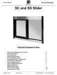
gyro moves. Figure 3.1
is
an
example of a cUp region implemented on an attitude gyro.
B.
PERSPECTIVE REGIONS
A perspective region is, in a number of respects, similar to the clip region [Ref.
p.4-4]. It is
2,
a specific portion of the workspace window that can be utilized to provide
31
Figure
3.1: Clip
Region Implemented on an a Attitude Gyro
a changing frame of reference within that region while the viewing perspective of the
area outside of the perspective region remains fixed.
the cUp region and the perspective region
to
an object that
is
is
The primary
in the fact that the clip region
structure. If the workspace area
cockpit, the perspective region provides a
then available of defining how
application.
The procedures
defining the area
a
file
is
applied
is
we
referenced to the entire
Additionally, to create a perspective region, an external page
must be added to our
is
between
indigenous to the structure (such as the attitude gyro that
created in the last section) while the perspective region
workspace window.
difference
space will be required for a particular
entail defining a specific
to act as the viewing model.
will
viewed as the interior of a
window to the "outside world". The option
much window
on the screen that
is
group as a perspective region,
be utilized as the viewing port, and importing
Before beginning however, the workspace must
32
be configured so that the perspective region
Take the
will
provide a meaningful presentation.
you just created with the attitude gyro and the
file
clip region,
and
start
from
there.
The procedures
•
Open
the grid attributes icon, and increase the size of the grid to a point that
are as follows:
the attitude gyro created in the last section occupies about a third of the grid
width.
Zoom
out until you can see the complete grid, and translate the entire
attitude indicator structure to one side of the grid to provide a cleax area in the
center of the workspace.
•
Change the parent
to the
file
new group attached
header, and create a
to the
header. Toggle to the structure chart, select the group you just created, and
open the Modify
attributes editor.
was accomplished with the
•
Once
on
again, the
this box,
you
for a
Change the Group type (very similar to what
clip region) to
a perspective region.
box labelled Pick reference Points
will
become
active.
and toggle back to the workspace. The dialogue box
LL
(lower
left)
reference point,
and an
UR
will
Click
prompt
(upper right) reference
point. This time however, they will be referenced to the entire
DWB workplace
viewing area. The size of the area defined will be the size of the viewing window.
Pick an area that
is
roughly square and does not overlap any of the attitude
gyro that was moved
Attributes
box
off to
for that
a "normal" group.
the side.
You
will notice if
you open the Modify
group again, that the group type has reverted back to
This occured because
aji
external page has not yet been
attached to the group that was specified as the perspective region, and thus,
there
is
no
file
identified as the "picture" that will
"outside world".
33
be imported to act as the
•
At
you created the attitude gyro in the same database a^ the cube
this point, if
created in Chapter
II
again as a different
be the import
•
and are working
name. One
file
Make
file.
in that file
will
be the working
sure the right path
the
submenu
Open
you
for the
in or double click
on the
the dialogue box.
Now
if
file
name
external
file
A
of the external
file
file
file.
the import
is
menu box
to import. Either type
file
under, and close
you toggle back to the structure chart, you
is
will
to the group that was just created
name you saved
The green box
it
the Structure pulldown menu, go to
that attached to the group that you created
attached to that.
and the other
and choose the external page option.
of Create
will appear, asking
region.
file,
and then save
it
specified for the save as
is
Reopen the working file and change the parent
and changed to a perspective
now, save
will notice
a green box with a white header
the external page, and the header box
is
the
that you just imported.
An
Important Note:
file,
you must open the
you to modify a
file
If
changes need to be
original
while
it is
file
in
made
and modify
it.
in the
The
imported external
software wiU not allow
an import or external status.
• Reselect the group that contains the page. Notice that the page
box both become highlighted.
and the header
Toggle back to the graphics screen, and you
should see a "window" in the middle of your workspace screen that shows the
contents of the
group selected,
file
that was identified as your import
select the
file.
With the same
Modify Attributes option again, and you wiU find that
the group you identified as a perspective region
perspective region.
34
is
now indeed recognized
as a
utilizing the Perspective Region
1.
The
be hnked and
clip region created previously
utilized.
the picture in the
may
The
window
is,
and purposes, ready to
for all intents
perspective region, however,
of the perspective region.
is
another matter. Examine
It will
appear to be
tilted
and
either appear as an extreme closeup, or as a very distant view. Toggle back to
the structure chart, select the green page box, and open the Modify Attributes page.
This editor allows modifications to the attributes of the external page, and thus the
properties of the viewing area.
a window for
for position,
window
for aspect ratio,
The software
X. Change
It
has three windows for rotation, three windows
field of view,
a button
for active page,
defaults for the rotation
X
a window for color, a window for scale, a
windows
to 0", and select Apply.
and a window
are: zero for
You should
region change to an overhead view looking directly
database. Note also that the background color
(if
Y
for
page number.
and Z, and 45"
see the view in the perspective
down on the
you can see
grid of the imported
it) is
black. This will be
the case regardless of what the original backgroimd color was in the imported
to the color
of the Modify Attributes page,
you would Uke the background
color that
know the
window
color
number of the
color
utilize,
Select the
is
Go
be
(if
you don't
open the color palette,select
the color you want, and note the index number in the lower
palette. This
file.
and enter the color number of the
in the perspective region to
you want you
for
left
comer
of the color
the number that goes in the color box of the Page attributes editor).
Apply button again, and the background color
in the perspective region
will change.
It is
appropriate at this time to mention the fact that with the addition of
the perspective region to the database, the possible
number
systems in the "world" has increased to three. There
is
of reference coordinate
the coordinate system con-
tained in the monitor screen (x being positive to the right, y being positive up, and
35
z being positive out of the monitor), the coordinate system of the instrument panel
the attitude gyro), and finally the coordinate system of the
(i.e.
the perspective region.
and there
other,
is
It is
file
contained within
possible to have these three systems orthogonal to each
nothing technically wrong with that.
possible however,
If at all
you should try to maintain as much coplanarity between the coordinate systems as
possible, as this will greatly reduce the bookkeeping
workload when the time comes
to link the simulation.
As
tion
for the
remainder of the Page attributes editor, you
and rotation windows
way you would
for
moving about
in the workspace.
may utilize the posi-
in the perspective region
Ensure that the Active Page button
and check to make sure that the number
in the
will
a discussion of two additional features in the Page attributes page.
and aspect
scale option can be useful
and the working
radically different.
working
file
in
file
in
because
close
the sizing factors between the im-
Let's say, for example, that
you created the cockpit
file
file
(the
however, you neglected to change the
and instead, created an object that was 6 inches square. In
would be extremely
it
if
which the perspective region was generated) on a grid scale that was
scale units to feet,
it
These are the
which you created the perspective region are
1500/t X 1500/t. In creating the import
case,
conclude with
ratio features.
The
file
depressed,
Scale
a.
ported
is
the same
Page Number window matches the
page number in the green box in the structure chart. This section
scale
much
difficult to utilize this
would be hke trying to see a salad plate
object in the perspective region,
in a large parking lot. If
enough to the salad plate to detect small changes
close to the parking lot to
be able to
tell
this
in attitude,
where you were.
If
you were
you would be too
on the other hand, you
were far enough back to be able to maintain a relatively good sense of perspective
36
with respect to the parking
you would be too
lot,
discern any useful information from
it.
In this case,
scale factor in the perspective region to
it
away from the salad plate
not completely accurate,
something on the order of 100. This would
will render the
it
model much more
The
aspect ratio feature
is
Now, go back and look
file is
not a square
field
window that
is
twice as long
at the picture in the perspective region. It will
appear to be stretched and distorted. This
the import
useful.
not square. Try for example changing
the reference points of the perspective region to create a
high.
and while
used primarily for the case in which the
is
perspective region aa viewed on the workspace
it is
ft,
Aspect Ratio
b.
as
to
would be prudent to charge the
change the dimensions of the salad plate to 600 inches or 50
effectively
maybe
far
will also
occur
if
the
and the perspective region
file
you identify as
is.
SOME NOTES OF CAUTION ABOUT PERSPECTIVE REGIONS
•
Any
links that
you have
page) will be deactivated
attributes
built involving a perspective region (i.e.
when you modify something
in the Page
editor and select either the Apply or Ok button. If you change
the Page attributes and accept the changes, you must reload the link
•
file
before running the simulation.
Be
careful
when
Page attributes.
using the Scale or the Aspect Ratio function in the
If
you change the scale of the imported image
in the
perspective region, this scale change will not be carried over to the
data driving the simulation.
the field by a factor of
2,
If,
for
example, you increase the size of
the position data being input to the simula-
tion will appear to be decreased by half,
the visual presentation.
The same
37
and
it
may
significantly alter
applies to the aspect ratio except
gets even trickier. In this case, the imported
proportions
that
it
may
not be scaled by the same amount in each direction, and
get very
messy trying to
ratio changes.
scale the
perspective regions approximately square.
much
easier.
38
it
can
incoming data to match the aspect
If at all possible, try to get
of linking the simulation
file
the import
It will
file
make the
and the
process
IV.
LINK EDITOR
The previous chapter explored the techniques involved
editor to create a
3-D
in using a
aircraft,
life.
The
is
carried out
procedures ajid data necessary to accurately "fly" our aircraft [Ref.
p7-l
3,
7-43].
The models created
in
DWB
are, for all intents
and purposes, "dumb". They
cannot determine whether a particular feedback gain
is
going to be destabilizing,
or recognize that the aircraft caimot fly in equilibrium at
90''
serve only as graphical representations of information that
is
source. It
is
this attribute of the software that allows
to the
cube created
"fly" the cube.
in the previous chapter,
Of course the value
angle of bank.
They
delivered by an outside
animation links to be applied to
any object that we create. For instance, the dynamics of an
it
process
This chapter will examine, in
in the portion of the software called the link editor.
-
be either Bluebird
Having constructed an accurate model of either or both of these
a method must be devised to bring them to
detail, the
graphical
model or simulate a physical
object that can be used to
process. In this chapter, the physical process being modelled will
or Archytaa in flight.
2-D
aircraft could
be linked
and an animation developed that could
of the visual feedback
would be minimal, but
could be done. With that in mind then, the following discussions relating to link
operations will be geared toward the Bluebird and Archytaa simulations.
The
link
processes described in this chapter are based on working simulations of both aircraft.
The
user
may
choose to use these models, or create an aircraft model of their own.
The chapter will conclude with a
detailed
example of linking Bluebird
region environment.
39
in a perspective
VARIABLES
A.
Whether the data used
model comes from a data
to drive the
shared
file,
mem-
ory or from an ethernet connection (more on these topics in the next chapter), a
standardized
way
of presenting
it
to
DWB
must be
defined.
be reproduced on the screen must be driven by some
The
action that will
For
sort of defined vajiable.
beam might
example, generic simulation of simulating a rotating radar
use as the
driving function, a constant times elapsed time in the azimuth plane, and a sinusoid
a dynamic simulation that provides interaction, the variables
in elevation plane. For
that used to drive the model will have to
must be created by the
user.
come from
outside
DWB's framework and
There are two types of variables available
for driving a
simulation: internal variables, and external variables.
Internal Variables
1.
Internal variables axe those variables that have been predefined in the soft-
ware.
A
listing of these variables in
Note that
shown
in Figure 4.1.
in addition to the variables listed here,
you may
combination of these variables as another internal variable and add
The only
stipulation here
is
2.
it
to the
that the drivers for the user defined function
contained in the internal variables
any
also define
list.
must be
listing.
External Variables
External variables are the user defined variables that identify the data
being presented to
accessable to
DWB from an outside source.
DWB
that contains a .vars extension in the
discussion of the .vars
is
shown
These variables are defined in a
file,
refer to
Chapter V.
A
file
file
name. For a complete
portion of an external variables
file
in Figure 4.2.
Unlike
DOS,
the variable names are not limited to 8 characters, and should
40
I
I
I
I
irems
constant function:
cos function:
dummy variable:
I
elapsed time;
frame number:
I
I
I
I
ramp
I
(unction:
I
sin function;
square wave
t
ftinction:
tan function;
i
Figure
be made as verbose as
is
CarKcl
Apply-
I
variable contains.
I
I
current lime;
I
f
FLOAT Constant value
to
FLOAT Trig function.
since
start
of
day, in seconds
FLOAT Time
FLOAT Default var used by controls
FLOAT Time since start. In seconds
Animation frame, to N
INT
FLOAT Triangular Wave, to
to 1
FLOAT Trig function,
FLOAT Square aiQQil pulse, to
FLOAT JHg function
4.1: Internal
Variables
necessary to provide a complete description of what the
Once the
.vars
file is
created,
it
may be
used for a wide variety
of simulations as long as the format of the data being input does not change.
example, the
file
Perspectives. drt
B.
if
Showtime. vars
used to drive the simulation contained in
the same data format was used for both simulations.
OBJECT LINKS
The
act of linking an object
primary application of
be focused on
is
this software
Bluebird or the Archytas
will
may be
For
what brings the simulation to
is
life.
Since the
to facilitate flight visualization of either the
aircraft, the link discussions in this
aircraft apphcations. Obviously, the
to other applications aa well.
41
and the following sections
same philosophy would apply
j
)
'
;
y'yyyyyy.fr^r'yyyyyyy^'yyyyyyyyyyyyyyyyyyyy.'.'ij-yyyyKr'yyyy.^
ijiiiiil
SwSSJiSiftixSS-SSiSSSSSSSS^^^
:::-;S--
Itfinii
:
ocrivf?
p.
^ti-ivpef
10
IMf
|.a.]e:
Attrron ;
1:
:|
:
f
<
(raa
iOA) to
t
pi
x'J>
OAT fO
1
ri(iht r ->itr
t><»sitiv<'
^tt/^pc taie)
1
:
I'.t
1
1
CAT to (r.vt ponitivt? prtdi 1own)
OAi K^ (roll rate rad'se--)
17
;;::p;
y
f
f
:.
MOAI
r'l'f;
;.
i
ipP^it;
J
;:
f
;-|-;-;r;
j
iipare
1;
1
1
:SC.Ore
::
t( !A t
10;
.
r;|;;sit>^re:;;;
1Z;
::: sf.nj-e.
Kl;.;
spare
li: apnrP;.
io
IO
1
:x;v.
:;.
.
.
:;;;*-:
x:
1
v
< f
e (}
{)>tr^ 1^ ratfi
OA) iO
ra<l,
»•--)
(t
t!J<))0
uo to
)<)»)!!
j^
i
"i
J
:,;:,_,:::,:
IvtT y. tW)
:;::':
-':
:/
1
:
w
^
^^
ru>Ar to,;»J||||||:;:
n.OAl J(> :^J-iiiliiH^-
S
;
m-':-M
\
:liili: Six:--
mm
.
f-LOArtO::;':J4:-:;;;v:::::::x;^^
fO;:3^^
rroAT to
i
r^^^^^^^^^^
-: -1
1
:-:
•
:::^. ttxMrto^^.:^^^
li);
-.^^^^vwwwwwv.
'-.-^•''^ww.,^^'''^-''•-^-'— -•-^•'''''''•••'^-''^----''''^^^^^
S;
1
;.iu t<
rad/^cc
(fad |>o?irtv'f
mj':^d:::
;'::'":::;'rt(:)AT
14;';
'li/.:*
()e<i
1
(yav^ rr.te rad^^ec
(3
HO At
:
It;
|;;
to f;j/J
oA r
C) A 1
fi
p'^parc,;
|::
1
ctKfdftf ;:,;
:;
1
——.™
.,x|x,_
;
Af.pfy
;
,:
.
,
*
WSWJ8S9
:
j
!
I
Figure 4.2: External Variables in the .vars File
Using any sort of external information source, be
memory to
it
drive the simulation requires that the .vars
plished
by opening the Link pulldown menu, and
option.
The standard
file
the appropriate .vars
file.
of links can begin.
The
data
file
first
variable
ethernet, or shared
be loaded. This
selecting the
dialogue box will appear, and
Once the
file,
all
is
accom-
Load Sim Names
you need to do
is
select
names have been loaded, the creation
step in the linking process
is
to select, using the pick
function, the exa<:t object that you want to link. In the case of an aircraft link, you
must
select the entire aircraft as a
object name).
group because
It will
DWB
you want to link a
group (each link process will be identified by one
not work to select the 250 faces that comprise your aircraft
will not
specific
be able to determine which face you want to
link.
If
item within a group, say for instance, the needle on the
airspeed gauge, you can select that particular face
42
if it
has only one face, or
move
all
of the associated faces into a separate group.
A
move
When
Point of Technique.
as a single unit (as
would be the case with an
to toggle to the structure chart
you want to
link.
complex structures that you want to
linking
and
aircraft),
it is
uppermost group
select the
As an example, say you had created a group
attached groups containing the various substructures.
out of the workspace, what you will get
to the structure chart
and
select the
select all of the substructure items
is
the
list
and
it,
called Bluebird, with
select Bluebird
of the various subgroups.
will allow
eeisier
in the the structure
you try to
If
group named Bluebird.
below
considerably
It will
Go back
automatically
you to create a
link called
BluebirdJink.
Once the object
and choose the Create/Edit option.
Figure 4.3 wiU appear.
If this is
the
A
blue dialogue box similar to the one shown in
first
link for the object, or
before but have not loaded that particular link
shown
menu,
to be linked has been selected, go to the Links pulldown
file,
if
you have linked
it
there will be one entry listed as
in Figure 4.3.
DWB will default to a translate Unk.
and choose the appropriate
To change
link operation. For
some
this, click
on the
select
of the links, the editing
button
box
appeax autoniatically. For others, you must
select the edit
button to define the
The
more common
linking operations.
following discussions detail
1.
some
of the
will
link.
Translation and Coordinate Links
Translation links accomplish just what the
to translate an object through
some specified path
of the translation link will be to
aircraft as defined
in space.
map external variables
by the workspace
grid.
name
They allow you
The most common useage
to the x — y — z positions of the
The coordinate
43
implies.
link
is
simply a grouping of
Help
Link
Name
{)1
link
pi Jink_op_1 (translate)
Link Operation Selection
p1Jink_op_l
Operation Type
translate
Apply
Figure
4.3:
Select
I
Cancel
Edit
Link Create/Edit Dialogue Box
the traxLslation links for the principle axes combined into one editing box. These are
used primaxily for grouping multiple translation
links
as long as the
do not require complex mapping. For most of the applications relating to
project, the coordinate link will
to date, the controller
controller,
and z
and work well
links,
and
it
be completely
satisfactory.
model used to generate the data
files
was therefore extremely easy to define
positions. For other flight models,
directly the aircraft inertia! position,
and
it
may
For the simulations run
was an
inertia! trajectory
as external variables the
this will require
some
sort of transformation
w
states multiplied
(Note: u, v, and
w
vectors define the velocity of the aircraft with respect to the
by elapsed time to provide an
44
a:,y,
not be as straightforward to generate
and
of the w, u,
this
inertia! position.
body
frame of the
By
aircraft.
convention, the forward velocity component u
out the nose of the aircraft, v
is
positive out the right
wing of the
positive
is
aircraft,
and
w
is
positive down.)
At
as a
this point in the discussion,
"dumb"
editor x
linking a
—
y
it is
necessary to reiterate that
terminal. The orientation of the Unked object with respect to the
—
DWB
z grid planes
very important.
is
Let's
walk through an example of
aircraft to it's inertia! position as derived
from a separate controller
simulation. For the purposes of this discussion, assume that the
model has the capability of providing the
also
assume that the
The
inertial x-position, y-position,
scale of the
required. Furthermore,
z axis
is
wing
is
file
an output. Let us
and z-position have been defined
scaling of the incoming data
assume that the construction of the
is
controller
labeled, respectively, xjpos^ y-pos,
DWB model is such that
such a way that the nose of the aircraft
grid, the right
dynamic
aircraft inertial position as
as three external variables in our ,vars
z^tos.
DWB acts
is
and
not
DWB model was done in
pointing along the positive y axis of the
pointing out the positive x axis of the grid, and the positive
out the top of the airplane. Finally, assume that the standard convention
of aircraft position labeling has been utilized to generate the data,
positive out the nose, y position
the bottom of the aircraft.
The
is
positive out the right wing,
i.e.
x position
and positive z
is
is
out of
position Unks will be created using the coordinate link
option. Select the entire aircraft (again, ensure that only one group
open a Create/Edit new Unk box. Select the coordinate
link
is
identified),
and
and the editor shown
in
Figure 4.4 will appear. As you can see, there are three available windows for defining
a position mapping.
The windows
names
(or the
mapped
that have the phrase frame
variables) defined in the .vars
immediately adjacent to the
X
Mapped
to phrase,
45
number are where the variable
file
will go. Click
on the window
and then move up to the
Select
||
Global
I:
Item
Select
Help
Viev/
...........
f
Jamc
^ Link Op.
,:..
p12U
p1?njink_of>_1
Marrie
coordittale
j!
Link Type
|;
X Mapped
To
frame miinber
Var
|:
Y Mapped
To
frairie
nuiriher
Var
|i
ZMappodTo
...
^fr.itnt; number
Var
|
Can
el
mmuitmimmmmsmsaimim
Figure
pulldown menu. The
first
Coordinate Link Edit Box
4.4:
entry
is
Variable, with a
submenu
to allow
you to choose
either external or internal variable. Select the external variable option,
of the external variables available in the loaded .vars
aircraft is pointing in the direction of the grid y axis,
to the
X position.
Similarly, the
Finally, the
directions.
We
need to
map y^os
to
X
will appear.
listing
Since our
we cannot simply map x.pos
position for the proper orientation.
Y position on our grid is going to be driven by x.po3 from our data file.
Z position will come from z^os, but the two axes are pointing in opposite
Once you have entered
z4)os in the
Z
the select pulldown menu, and choose mapping.
to the one
file
and a
shown
in Figure 4.5 will appear.
46
position
mapped
A Mapping
to
window, go back
function editor similar
i?
J!
|:
Global
Mapping For
p129Jink_opJ
Function
unmapped
Assignment
None
Variable r~
r-
Apply
Figure
4.5:
[X]
variable
frame number
X
|:
Select
Cancel
Mapping Function Editor
Open the Select pulldown menu of the mapping editor, and
A
option.
list
and since
of available fimctions will appear,
to reverse the direction of our mapping, select linear.
a means for multiplying the variable by a value
a constant, or can in
itself
again, the coefficient
C
this case,
the
C
make the
coefficient
mapped
for this case,
linear
we only want
mapping wiU provide
(this coefficient value
can either be
be a mapped fimction), and/or add another value (here
can either be a constant, or can be a mapped variable). In
A coefficent —1
to change the sign
on the incoming data and leave
uchanged. Click Ok for this editor, and aircraft
to the —zjpoa external variable. Click
link editor,
The
select thefunction
and the coordinate
link
is
on the Ok button
Z
position
is
now
for the coordinate
complete. Utilizing translation links instead
47
if
the coordinate link would have required the same operations and provided the
results.
same
This would, however, necessitate that a separate link operation be defined
each channel of the position data.
for
A
window
Point of Technique: The var button
in the link editor
of variables. If
shown
you have a
Ust of external variables.
.vars
If
in Figure 4.4
file
is
off to
the side of the mapping
a shortcut button for retrieving a
list
loaded, selecting the vax button will retrieve the
there are no external variables loaded, the
list
of internal
variables will appear.
2.
Rotation Links
"he next type of link to be discussed
is
a rotation link.
you would see the
to be started after creating only the position links,
around the sky in the orientation
in
a straight
line,
started in initially.
it
everything will be ok.
If,
Were the animation
As long
aircraft
moving
as the aircraft flys only
however, the aircraft will be required to
turn or manuever, there must be some sort of rotation applied to the model. As before,
an example
will
be utilized to
illustrate the
method
of Hnking rotation variables.
As
previously stated, the assimiption will be that Euler (or inertial) angles are available
from the data
.vars
file
file,
two
and psi
as phi, theta,
selected as a group
using the
and that they have been
respectively.
same object you used the coordinate
entries in the box.
The second
4.3).
to those of the previous section.
you
before, ensure the entire aircraft
will
link
on in the
last section,
is
If
you are
you
will see
entry will be the default translate link operation,
and change the
appear as before (see Figure
as radians,
As
and choose Create/Edit from the Link pulldown menu.
so highlight that one,
file
identified as external variables in our
link type to rotation.
The mechanics
If
The
link editor will
of creating the link will be similar
the Euler angles are brought in from the data
need to convert these to degrees, which can be done with
the linear mapping function as
we
did with the
48
Z
position mapping, except the
A
coefficient will
link, there is
be 57.3
(to convert
no "coordinate"
separately. Let us link
(/>
Now, you must
it
has no idea that the variable
rotation link.
Unlike the translation
Each rotation
link
must be defined
Select phi out of the external variables
first.
to our
Remembering that the
reidians to degrees).
link for rotations.
it
first
from
is
<f>
define the plane of rotation for
supposed to be a
aircraft is oriented
file,
with
roll
and apply
DWB since
about the longitudinal
ajcis.
nose in the positive y direction, a
its
proper phi link to the aircraft will be accomplished by choosing Plane under the select
menu
be the x
to
the aircraft
—
z plane.
If
you were to animate
The other two
A coefficient or reverse the plane
by selecting reverse under Select/Plane pulldown menu).
of rotation (accomplished
rotation channels will be identical except that 9 will be
rotation in the y
— z plane,
and
ip
wiU be mapped to rotation in the x
be mapped through a Unear function with a
So
now, you would notice that
banking, but in the wrong direction. This can be corrected in one of
is
two ways. You can either attach a minus sign to the
will
this
far,
—y
mapped
plane.
to
Each
coefficient of 57.3.
the rotation Hnks created have
mapped
angles to angles. There
is
another type of rotation that can be applied to a simulation as well that involves
mapping
of link
"translation" data to a rotation.
would be the rotating needles of
The two primary examples
either
In order to create a link of this sort, there
of this type
an airspeed indicator or an altimeter.
must be a defined
limit
on how
far the
needle will rotate in representating the data or, in other words, define a mapping
between forward airspeed
dial. Let's
a translation quantity), and the rotation of a needle on a
say for example that
needle measures the
from 1000
(
—
10000
ft.
—
1000
we have an
ft
altimeter that
we
The requirement
will first select the
"1000
good to 10,000
ft.
One
increments, while the other measures the altitude
is
to
Hnk the needles on
altitude of the aircraft, but the aircraft altitude
this,
is
is
a "linear" quantity. To accomplish
ft" needle, create
49
this altimeter to the
a new rotation link, and
map
the
z^os. Immediately below the Mapped
link to the variable
windows labeled [lower mapped
limit]
and [upper mapped
window, there are two
to
At the bottom
limit].
of
the page will be two windows labeled Rotation at min and Rotation at max. For the
needle (our "0
first
upper mapped limit
be 360. For the "0
1000"
-
ft
needle), set the lower
at 1000. Rotation at
-
10,000"
ft
max will be
be zero, and the rotation at
5000
ft,
the
first
will
360.
limits,
and
K you
we
same
thing.
be 10,000
With
will
it is
limit at zero, ajid the
be zero, and rotation at
ft.
The
max
rotation at
and with the
is
360),
is
created,
will
limit
min
will
aircraft at
and the second
halfway between the lower and upper
have rotated 180°.
noticed, there was no need to select a rotation point or origin
created the rotation links for the Euler angles of the aircraft.
Unk
max
The lower mapped
this setup
needle will be straight up (rotation at
needle wiU be pointing straight down, since
mapped
will
needle, do the
be zero, and the upper mapped limit
will
min
mapped
When
when
a rotation
DWB will default the center of rotation to the centroid of the object,
and in the case of the Euler angle
rotations, this
was exactly what was desired since
the centroid of the model closely approximates the center of gravity of the aircraft.
A
rotating dial indicator however, needs to have as
i-he
needle.
While you
still
At
center of rotation the base of
have the link editor open, go to the Select pulldown menu,
and choose the Origin option.
or point of rotation.
its
A
new
dialogue box will appear asking for the
this time, select the base of the needle, close the select origin
dialogue box, and accept the links you have created.
finks to the three positions
The
and three rotation angles of the
aircraft altitude represented
on a rotating
dial indicator that
link
file
aircraft,
now
and
consists of
links to the
can be used in a cockpit
environment.
3.
Some
origin
Final Notes on Object Linking
Next, several lessons learned using object linking are discussed.
50
•
Translation links must
come before
rotation links.
the the links in the link
in the order in
which they axe
file
translations get executed
That
is,
first,
listed.
will process
As long
aa the
the simulation will be slaved to the original grid.
the animation routine will translate the object through the original
frame of reference.
If
however, you placed a rotation link prior to the execution
changed by the rotation
of a translate, the reference coordinate system will be
links.
DWB
What
happen
will
is
that the object will
still
translate along the original
coordinate frame, but the rotation links will not remain fixed to the
same
refer-
ence frame. This will cause your linked object to essentially "tumble" through
spa<:e.
•
Rotation Link Order The normal order
rotation
DWB
is
3
-
2
-
1 (V*
— ^ — ^).
of rotation for a
body
to inertia!
For some reason, ordering the rotation links in
seems to work best in the
2-3-1
(^
—
V'
—
<^)
order. If
you cannot get
your linked object to respond properly, try changing the order of the rotation
links.
•
Clip Region Links. In order to successfully
going to
make an
link
a
clip region, (i.e. if
you are
attitude gyro), the structure of the major group that contains
the sphere must look like this:
Clip Region
Group
Link Group
In other words, create a sphere, color
(for
it,
and attach
all
of the pieces to a group
purposes of illustration, this group will be called the link group). Now, take
51
that group and attach
region group.
The
"know" that a
and
C.
to a group one level above
it
result of this structuring
clip region exists,
link groups are
is
this
and the entire sphere
is
clip
will
move.
If
the clip
reversed in the structuring,
the link will attempt to
move the
appear that the gyro
sliding off of the backplate).
clip region,
one called the
that the link operations do not
one in the same, or the order
is
it,
with unsatisfactory results
(it
will
EYE POINT LINKS
Eye point
links are extremely useful
from a simulation design standpoint. Rather
than attempt to identify a single fixed point
simulation, they provide the flexibihty to
vide a relatively simple
method
in space
from which to view an entire
move with the animation. They
for viewing a simulation, as
also pro-
they can be used without
adding the complexity of external pages and perspective regions.
If
you are building
a database with a model that will eventually be imported into a fuU scale perspective
region, the eyepoint feature
go.
To
is
a good way to test the links and external data a^ you
create an eyepoint link (in a non
-
perspective region environment), the
file
header must be the link object. Eyepoint links are fundamentally different from the
regular object links in that the frame of reference used for the eyepoint
to the monitor screen (or eye port).
is
always fixed
Recall that the object links that discussed in
the last section were grid dependent. That
is, if
you changed the orientation of the
database with respect to the grid, the link orientation would also change. With eyepoint links, the monitor
is
screen toward the viewer
(
always the x
x
is
—y
plane,
and z
positive to the right,
is
and y
always positive out of the
is
positive up). Therefore,
the eyepoint link mapping can be very different than the object link mapping.
Eyepoint links will be created in exactly the same way that translation links
were defined for the
aircraft.
The eyepoint x — y —
52
z positions
must be defined with
respect to the external variables, as well as any rotations that
eyepoint.
Once the eyepoint
links
have been defined,
it
will
may be
desired for the
be necessary to determine
a starting position for the eyepoint. The default starting point
is
the grid origin.
If
the objective of a simulation was to follow an aircraft through a series of maneuvers
while in
the X
—
flight, it
y
—
may be
best to link both the eyepoint and the aircraft positon to
z position external variables.
starting position,
and
also
had the
Now,
if
you accepted the default eyepoint
aircraft starting at the grid origin,
would be
see the aircraft during the simulation because the eyepoint
To coimter
this, select
of the aircraft.
if
right
on top of it.
the origin to be a point somewhere behind the starting point
The other option would
the aircraft by actually translating
especially
you would not
it
of course be to
in the database,
move the
starting point of
but this can get cumbersome,
you are dealing with a perspective region, and the associated external
files.
As a
final
initial position
note about eyepoint linking,
it is
pertinent to point that the eyepoint
could have also been changed through use of the mapping editor. This
method does have
its
drawbacks, and can get extremely complicated. Let's say, for
example, that you had linked the eyepoint and the aircraft to the same translation
variables,
and had linked the eyepoint
be looking at the
aircraft
the eyepoint, you simply
minus 200
ft,
to rotate in such a
from behind. K, instead of changing the
mapped the eyepoint x— position
the eyepoint would indeed jimap to 200
simulation started.
If
be "in front" of the
manner that
ft
it
would always
initial position of
to the aircraft
x— position
behing the aircraft when the
the aircraft were to turn 180" however, the eyepoint would
aircraft
and looking
in the
wrong
direction. This
is
not to say
that this type of eyepoint position linking could not be accomplished, but
require a degree of sophisticated linking.
53
now
it
does
D.
PAGE LINKS AND LINKING IN THE PERSPECTIVE REGION
Page
links are the tool that
a perspective region.
If
we were
the previous section,
it
would
perspective region, and
it
we
will use to link the eyepoint
to link
'^he
header of the working
effectively leave the viewer static
file
as
axe utilizing
was done
in
with respect to the
would create a sense of moving about the cockpit. Aside
from the link object however, the mechanics
perspective region are
when we
much
for creating
an eyepoint link in the
the same as those discussed in the previous section.
To
create an eyepoint link in a perspective region, you will need to link the external page
to
which the imported
chart,
file is
attached. Select the external page box in the structure
and Create/Edit an eyepoint
created in the last section.
link for
The most
eyepoint link in a perspective region
it
in the
same manner
significant complication that
is
when the coordinate systems
as the eyepoint
can axise with an
for the databases
are different. Recall from Chapter III that, by the time you get a perspective region
and cockpit display constructed,
and the
airfield
it
is
possible for the eyepoint, instrument panel,
coordinate systems to be orthogonal. This can significantly increase
the complexity of the links in the simulation.
of orthogonality in the databases,
is
always based around the x
positions
you
system of the
—
link the eyepoint
file
If
you do end up with some degree
remember that the eyepoint coordinate system
y plane of the monitor screen and the variables or
movements
to will be referenced to the coordinate
imported into the perspective region.
54
V.
now
This leaves us
COMMUNICATION
in a position to discuss the options available for driving
a simulation from an outside source
[Ref.
4, sec.7].
DWB
supports the following
communication methods:
•
Data
Files
1.
ASCII data
2.
Binary data
• Shared
Memory
• Ethernet
1.
UDP
ethernet
2.
TCP
ethemet
Each
of these forms of
senting data to the
simulation, the
of the
DWB
comms
communication uses a
format for pre-
animation module. To configure the communications for a
editor
must be selected through the configure comms option
Animation pulldown menu. Figure
It is
slightly diflFerent
5.1
shows the conmis editor.
here that the method of communicating with
DWB
is
defined.
procedures for the different types of communications vary slightly, but
consist essentially of teUing the software
how
the information
is
identified.
communication types, and that
is
where the information
There
is
that ejich
data to be useful. This will be examined
all
set
of
up
them
coming from, and
one point of commonality between the
must have access to a
first.
55
is
The
.vars
file
for the
I/O bi'ieotion
I
Only
Inpul
C(>mtrr<j Mi'iluxl
Iii(hiI
r~
r~
Mc-iic
RccofftData
Apply
Figure
5.1:
CafK,ol
Comm
The
Editor
.VARS FILE
A.
The
4, p.4.2].
It is
.vars
In
it,
file
can be thought of as the phone book for the animation module
the user defines
all
here that the relative position of each variable in the incoming stream,
animations
The
First,
data
is
shown
.vars
file
A portion of the
up to 50
As
will
.vars
file
defined,
is
used for the Bluebird
in Figure 5.2.
contains two critical pieces of information about the variables.
what type of number the variable
field.
[Ref.
of the variables being presented to the simulation.
aa well as the format of that variable.
of
IaIiI)U<j
r~
IJone
Special Conli.jiJiation
r
CurrKnlly
be examined
variables.
The
is,
and second, where the variable
in the following section, the .data
.vars
file,
file
is
in the
allows the use
however, gives us the capability of defining up
240 variables in varying formats. Table 5.1
lists
the breakdown of the
number
type of variable allowed when driving a simulation with an ASCII data
56
file.
of each
For
all
float
float
float
float
float
float
float
^heta <«S7*? tJleg-racf* rSO to ^S)
p3t
(*S7.3 deg-rad, -98 to
'
iTpos
(ft)
(ft)
2 POS
elevator (rad posit ive-pjtch down)
Crad pos1t1ve*1aft yaw)
Figure
5.2:
other types of communication, there
is
The
no
.vars File
limit
on the number of variables that may
be defined.
TABLE
5.1:
.VARS FILE
STRUCTURE
Floating point variables
50
Character strings
40
The three variable types listed in Table 5.1
in the
.vars
for
are the only tj^jes of variables allowed
DWB environment, and for simulations being
must contain
150
Integer variables
driven by
ASCII data
files,
the
variables within the constraints of the values in Table 5.1. Again,
any other type of information
driver, the allowable
number
in not limited. For the purpose of the Bluebird simulation, the
57
of definable variables
data
file
consisted of
25 states and their values for a specified period of time, so the .vars
The names
150 available floating point variables.
suit
identified in Figure 5.2,
we wished
.vars
FLOAT
true^/s
FLOAT
ground_spd
(comment)
FLOAT
engine_rpm
(comment)
Once the
much
B.
as a .vars
it
file (for
file
might look
like:
variable)
copy an existing
them
in every time.
instance: showtime. vars).
Point of Technique: Rather than typing out 240
easier to
naming convention
example, in addition to the variables
(comment about the
and modify
file
it
lines of
a .vars
file, it is
accordingly.
DATA FILES
Driving a simulation with a data
file
as a stand alone process [Ref. 4, p.4-7].
interfaces active,
and
it
file.
row array of 51
incoming data.
must be zero
must be of a
variables
(i.e.
tool.
Whereas the
fields.
If
filled.
means
of running the simulation
need not have any other communication
affords us the flexibility of reviewing past simulations, or
can be a valuable analysis
of the .vars
provides a
We
conducting demonstrations. While a data
of
that the
variables have been defined, you will not need to type
Rather, save
A
is
add the variables true airspeed, groundspeed,
to
and engine rpm, that portion of the
If for
used 25 of the
of the variables can be modified to
the individual application; the only constraint here
must conform to standard Unix format.
file
That
is
file
The format
.vars
does not provide real time capability,
of the data
file is
quite different from that
a colimmar array of 240
is
to say that the data
file
it
fields,
the data
must contain 51 columns
file is
a
(fields)
the simulation does not require 51 variables, the remaining fields
Within the data
floating point format,
character strings).
fUe, the first
and the
last 10
The number
58
40
fields after
the integer time step
columns are reserved
for string
of data points in each field
(i.e.
the
length of the coliinms under each row)
Additionally, the
Figure 5.3
is
first
colimm
DWB
are currently a
to stick to the
number
immaterial, but the
in the data
a portion of the data
possible to configure
is
file
in such a
file
must be a
ASCII data
used in the Bluebird simulations. While
manner that
it
5.3:
The
number
ASCII format. Since
This converted data
complete details
for
C
file
as such
it is
best
Department to date has been
nm
//// x
it is
in anything but floating point format,
through an executable
and
in
Matlab/Simulink
saving a sampling of each state to a data
the unused portions of a
saving this matrix in
can accept binary data, there
.data File
driven by data obtained from dynamic simulations
filling
it is
files.
All of the virtual prototyping conducted in the
The data was obtained by
is fixed.
set of sequential integers.
of bugs in that portion of the software,
Figure
workspace,
number of fields
it
Matlab
51 matrix with zeros, and then
not possible in Matlab to save a
first field
DWB
file
to a time step integer.
to drive the simulation.
doing this conversion are contained in Appendix
59
in the
became necessary to process the
code that converted the
was then delivered to
file
[Ref. 5].
The
APPENDIX B,
Through a process
in the
of trial
and
error,
it
was determined that a
significant
slowdown
animation occured when the sampling rate out of the Simulink simulation was
greater than about 10 Hz.
C.
SHARED MEMORY AND ETHERNET CONNECTIONS
Shared
methods
for
Memory and
DWB
to
Ethernet conmiunication methods are the two primary
communicate to the outside world
[Ref.
4, p.4-10].
time, the hardware and procedures for ax;hieving a real time link to
developed.
of these
here.
The documentation in
[Ref. 4,
methods of communicating, and
The implemantion
of either
chap
7]
DWB
the Unix/ Network system.
60
this
are being
contains a fairly indepth discussion
as such that discussion will not
method
At
will require
be repeated
a considerable knowledge of
VI.
CONCLUSIONS AND
RECOMMENDATIONS
A.
CONCLUSIONS
The addition
ware
in the
of
DWB
to the repertoire of analytical
and computational
soft-
depajtment has provided a major boost in the realization of flying a
VTOL/transition autonomous UAV. Having graphical visual feedback available to
the pilot significantly increases the chances for completing a successful mission.
software has also
alytical tool,
become an
of the ISI
AC- 100
processor,
phase.
The
software as currently installed
user friendly, and although a
number
of shortcomings
is
it
will also
be an
components before the
integral part of the haxdware-in-the-loop testing of various
flight test
an an-
integral part of the controller design process as
and with the addition
The
for the
most part extremely
and bugs were discovered dur-
ing the implementation process, the updated version of the software scheduled to be
released in
B.
Mar
'94 will correct the vast majority of these.
RECOMMENDATIONS
The
MBytes
of
software was designed to be run on
RAM,
and 24
SGI machines that had
bit graphical processing capability.
time have 16 MBytes of
stalled in the Avionics lab at this
graphical processing capability.
To be
at least 32
The SGI machines
in-
RAM,
bit
able to utilize the software to
and only 8
its full
extent,
the hardware needs to be upgraded. Aside from hardware upgrades that will significantly
improve the performance characteristics of the software,
it
should be noted
that the preliminary development of the virtual prototype models for this project was
conducted on release version 2.0 of
DWB. A number of bugs
61
and
utilization
problems
were discovered during this preliminary implementation. Rather than recount the
difficulties
encoimtered,
uled for shipping in
it
March
of the software has been
will
be
sufficient to
of 1994,
and
note that release version 2.1
initial reports indicate
improved by an order of magnitude.
62
is
sched-
that the performance
APPENDIX
All of the
files
A: LIST of
PROJECT FILES
that were generated during the course of this project have been
transferred to Professor
Kaminer. The following
I.
is
a listing of the
files
containing
the final version of several of the projects associated with this work:
•
PerspectiveSa.xxx.
PerspectiveSa (P5a)
is
a collection of
lation of Bluebird in flight driven
of a trajectory controller.
files
that were compiled to run a simu-
by data taken from a Simulink simulation
P5a was implemented using a perspective region
to
provide an out of cockpit view, with 5 cockpit instnmients linked to the simulation.
The
Bluebird
aircraft
and the eyepoint
is
Unked to the "actual" position of the
linked to the
is
commanded
trajectory position to provide a
means
of determine variations in the aircraft position
sition.
P5a
.ceo files.
is
from the commanded po-
found in /home/lagier/cs.world and has associated
The
.vars
file
aircraft,
.Ink^.drt,
and
used with simulation can be either showtime.vars or
perspectiveA.vars.
•
Archyt-show.xxx.
Archyt_show
Archytas in
from the
is
a collection of
flight.
controller,
The
file
files
compiled to provide a fictional rendering of
demonstrates the six degrees of freedom available
and the VTOL/transition characteristics of Archytas. At
the time of this writing, there was no data available to construct a data
file
showing the dynamics of Archytas. This would be a good follow on project.
•
Showtime/Showtiine2.xxx
The Showtime
files
were the
first full
63
animation
files
run during this project.
There
is
no perspective region or accompanying cockpit instrumentation, but
the degree of resolution
due primarily to the
is
better in these simulations than the perspective series
fact that there
quickly test a link or data
•
file,
these
is
a larger viewing area.
files
are well suited to that
If
you want to
teisk.
Importn.dwb
The import
series of files
were replications of Monterey.dwb used to import
into the perspective regions of the perspective series.
imports. dwb. This
in the
The
P5a viewing
is
the database you must change
if
P5a uses
it's
import
file
you want to mcike changes
area.
rest of the files in the directory are files that
to get to the files listed above.
They
are, for the
nonfunctional for one reason or another.
64
were used as stepping stones
most part, either incomplete or
APPENDIX
B:
DATA CONVERSION
PROGRAM
This
is
a reproduction of the
the PC-486 in the Avionics lab.
naatrix of
ffffxbl
floating point
C
language program that currently resides on
The purpose
tinclude <stdio.h>
tinclude <math.h>
void main (void)
C
float num;
int n;
int m;
int length;
int start;
char namein[20];
nameout [20]
of the
program
is
to take as input a
ASCII numbers, and rewrite the
an integer format.
char-
IN "C"
;
FILE *fpl,*fp2;
65
first
column
into
;
;
;
;
;
;
\
printf ("This program takes a MATLAB data file saved in ASCII format \n")
printf ("and changes the first column's data structure to integer format \n")
printf ("in order to make it compatable as an input file to Designer's Workb
printf ("Please enter the file name of the MATLAB data file (ascii format).
scanf ("•/,s",namein)
printf("\n");
printf ("Please enter the file name of the DWB format file.\n\n");
scanf ("*/s",nameout)
printf("\n");
printf ("Hov
many rows (time steps) are in %s ?\n\n",namein)
scanf ("y.i",&length)
printf("\n");
fpl = fopen(namein, "r");
fp2 = fopen(nameout,"w");
for
(
n=l; n<length; n++)
{
for( m=l; m<52; m++)
{
f scanf (fpl , "Xf" ,&num)
if(
m«l
)
{
66
fprintf (f p2 "\ny.i\t'
,
'
,n)
;
}
else
{
fprintf (f p2
,
'7.6
.
3e\t " , num)
;
}
}
}
fclose(fpl)
fclose(fp2)
}
67
REFERENCES
1.
Coryphaeus Softwaxe,
Inc., "
2.
Coryphaeus Software,
Inc., "Designer's
3.
Coryphaeus Software,
Inc., "Designer's
4.
Coryphaeus Software, Inc., "Designer's Workbench Link Editor/Run Time Modvie User's Manual June 1993,
5.
License Manager User's Guide" June 1993.
Workbench Users Manual" June
1993.
Workbench Reference Manual" June
1993.
Hallberg, E. N. Design of a GPS Aided Guidance, Navigation, and Control System for Trajectory Control of an Air Vehicle,
Thesis, Dept. of Aeronautics
and Astronautics, Naval Postgraduate School, Monterey, CA, March 1994.
,
MSAE
68
INITIAL DISTRIBUTION LIST
No. of Copies
1.
Defense Technical Information Center
Cameron
Station
Alexandria,
2.
Library,
VA
22304-6145
Code 52
Naval Postgraduate School
Monterey,
3.
Dr. Isaac
CA
I.
93943-5002
Kaminer
Department of Aeronautics and
Astronautics, Code AA/KA
Naval Postgraduate School
Monterey,
4.
CA
93943-5000
Dr Richard M. Howard
Department of Aeronautics and
Astronautics, Code AA/HO
Naval Postgraduate School
Monterey, CA 93943-5000
5.
Chairman
Department
of Aeronautics
and
Astronautics
Naval Postgraduate School
Monterey,
6.
Thomas
CA
93943-5000
F. Lagier
73490 Siesta Trail
Pahn
Desert,
CA
92260
69
No. of Copies
7.
LCDR Mark
T. Lagier
TACTICAL AIR CONTROL SQUADRON TWENTY-TWO
FPO NEW YORK 09501-6542
70
DUDLEY KNOX U?^'"
HOOL
NAVAL POSTGRAD*..'
u1
93943-6.
MONTEREY CA
.
GAYLORD S