1
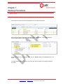
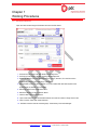
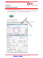
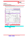
Resources iPDTekla 2.0 Manual
Chapter 1
Working Procedures
Reason for Revision
Original
Revision
Date
Prepared
Checked
Approved
0
04-Mar-2014
TGA
FCL
JMF
Procedure Number: Procedure Template - Number
DOCUMENT IS NOT CONTROLLED IF PRINTED
W: www.pdcgroup.com E: [email protected] P: (632) 634 8960 F: (632) 634 8961
Resources iPDTekla 2.0 Manual
Chapter 1
Working Procedures
Table of Contents
1
Model Setup ............................................................................................................3
1.1
1.2
1.3
1.4
1.5
2
General
Excel Design / Smiley
General
Part Numbering Series
The Numbering Setup
Numbering Parts
General
Creating Drawings
18
18
20
27
30
30
Issuing Stage ........................................................................................................39
6.1 General
6.2 iPDTeklaTransmittal Interface
7
17
17
Drawing Stage ......................................................................................................30
5.1
5.2
6
6
7
8
Numbering ............................................................................................................18
4.1
4.2
4.3
4.4
5
General
Site North Direction and Grid Line Views
Assembly, Part and Fitting Prefixes, Part Naming Conventions and Cost Codes
Detailing Stage .....................................................................................................17
3.1
3.2
4
3
4
5
5
6
Modelling Stage......................................................................................................6
2.1
2.2
2.3
3
Creating the Tekla model
iPDTekla Launcher
Tekla Structures Login Interface
Project Properties
Phase Names, BIM Phase Description
39
39
Reference Videos and Work Instructions ........................................................45
Procedure Number: Procedure Template - Number
DOCUMENT IS NOT CONTROLLED IF PRINTED
W: www.pdcgroup.com E: [email protected] P: (632) 634 8960 F: (632) 634 8961
Resources iPDTekla 2.0 Manual
Chapter 1
Working Procedures
1
1.1
Model Setup
Creating the Tekla model
Tekla models for Resources shall be registered first in the JMS model register.
After saving the register, initial Tekla model will then be created under “T:\Job No\900 Working
Documents\902 Native Models\Area” folder as below:
Full Model Names are automatically taken from the MODEL NAME and DESCRIPTION in the
above.
The initial model will then be copied or by syncing thru JMS Tool Suite by the assigned USER of
the model.
Procedure Number: Procedure Template - Number
DOCUMENT IS NOT CONTROLLED IF PRINTED
W: www.pdcgroup.com E: [email protected] P: (632) 634 8960 F: (632) 634 8961
Resources iPDTekla 2.0 Manual
Chapter 1
Working Procedures
1.2
iPDTekla Launcher
Open the Tekla model using the iPDTekla Launcher interface below:
1 - Preference for BLACK or WHITE Model View Background
2 - Preference for BLACK or WHITE Drawing View Background
3 - Select Job Number from this Pull-down Menu. Version, Division, Env and Firm will be
automatically filled-in upon selecting a Job Number.
4 - Select Model Folder from this Pull-down. For jobs created after IPD JMS System3 was
implemented, the default is on IPD folder.
5 - Select Job Area from this Pull-down Menu.
6 - Select the Model from this Pull-down Menu.
7 - NOT IN USE. Future Enhancement.
8 - Upon model selection, this will indicate whether the model is in Multi or Single User mode.
9 - Click to Launch Tekla after model selection.
10 - iPDTekla Launcher license remaining days. Controlled by Technical Manager.
Procedure Number: Procedure Template - Number
DOCUMENT IS NOT CONTROLLED IF PRINTED
W: www.pdcgroup.com E: [email protected] P: (632) 634 8960 F: (632) 634 8961
Resources iPDTekla 2.0 Manual
Chapter 1
Working Procedures
1.3
Tekla Structures Login Interface
1 - Default to be kept as iPDTekla
2 - Select a license configuration that suits your
role. If in doubt, ask your PM.
1.4
Project Properties
All entries will be automatically filled-in here. No need for user input, just confirm if all entries are as
specified in JMS.
Procedure Number: Procedure Template - Number
DOCUMENT IS NOT CONTROLLED IF PRINTED
W: www.pdcgroup.com E: [email protected] P: (632) 634 8960 F: (632) 634 8961
Resources iPDTekla 2.0 Manual
Chapter 1
Working Procedures
1.5
Phase Names, BIM Phase Description
The same application used in the auto-filling of the Project Properties at Tekla start-up, the Phase
Numbers and Names registered in JMS for each respective model will be automatically filled-in and
updated.
In addition, the BIM Phase Description column which will be used as additional properties for IFC export is
also automatically filled-in.
Users will just need to add Phase names that they might need for other interfaces like civil/concrete,
mechanical equipment, piping, cable trays and other electrical equipment.
2
2.1
Modelling Stage
General
For every project, a Site Layout Model will always be the first to be allocated, where a Site Datum will
be determined. From this location, setting out of the Structure Gridlines and Conveyor centre lines can
begin in accordance with the design drawings. In the absence of this, confirm with Project Leader as to
where to locate your model.
Procedure Number: Procedure Template - Number
DOCUMENT IS NOT CONTROLLED IF PRINTED
W: www.pdcgroup.com E: [email protected] P: (632) 634 8960 F: (632) 634 8961
Resources iPDTekla 2.0 Manual
Chapter 1
Working Procedures
2.2
Site North Direction and Grid Line Views
A weightless Site/Plant North direction dummy part has been created for insertion into the intersection of
the first X & Y Grids (e.g. Grid A – 1). This will just serve as a modeling aide.
Creation of Views Along Grid Lines
Below are the default prefixes of Grid Lines Views. This can be edited to match with the design
drawings or to the preferred view label in the Marking Plans.
You can also alter the View Properties setting preferred by clicking on the “Show” button.
Procedure Number: Procedure Template - Number
DOCUMENT IS NOT CONTROLLED IF PRINTED
W: www.pdcgroup.com E: [email protected] P: (632) 634 8960 F: (632) 634 8961
Resources iPDTekla 2.0 Manual
Chapter 1
Working Procedures
2.3
Assembly, Part and Fitting Prefixes, Part Naming Conventions and Cost Codes
1. Part Prefix is pre-assigned in JMS for each respective Phase and numbers are to be allocated
prior to detailing:
2. Assembly Prefix is commonly “AREA-PHASE NO-“
For the above snap shot for example, “CV161-01-“ for Phase 01 and “CV161-02-“ for Phase 02.
Refer to JMS information for each corresponding job.
3. Fitting Prefix, in addition to the Part Prefix, this may be added before the Part prefix, usually the
AREA-, is also pre-assigned in the Job Setup tab in JMS as below:
4. Part Naming Convention
Part Names are related to the Cost Codes being set in JMS. When modeling using the “Model
Builder Tool” in the iPDTeklaTool Application, Part Names are predefined and the appropriate
Cost Codes will be designated to the part upon modeling. It is very important to have the correct
part names as the Cost Codes rely mainly on it.
Procedure Number: Procedure Template - Number
DOCUMENT IS NOT CONTROLLED IF PRINTED
W: www.pdcgroup.com E: [email protected] P: (632) 634 8960 F: (632) 634 8961
Resources iPDTekla 2.0 Manual
Chapter 1
Working Procedures
Below are the predefined Part Names. Additional Part Names will be added if necessary:
PREDEFINED PART NAMES
BAR
HANDRAIL_WITH_KPLATE
SAFETY_GUARD_FRAME
BEAM
HANGING_HOPPER
SAFETY_MESH
BEAM_BFS
HBRACE
SHEDDER_PLATE
BELT_CLEANER
HBRACE_BFS
SHEET_RUBBER_CURTAIN
BELT_PLOUGH
HEAD_END_STRINGER
SHUTTLE_FRAME
BILLET_LINER
HEAD_FRAME
SHUTTLE_RAIL
BIN
HOLLOW_COLUMN
SINGLE_LEVEL_TRUSS
BISALLOY_LINER
HOLLOW_COLUMN_BFS
SITE_CLEAT
BONDED_RUBBER
HOLLOW_HBRACE
SITE_PLATE
BRACKET
HOLLOW_HBRACE_BFS
SKIRT_COVER
BRACKET_BFS
HOLLOW_POST
SKIRT_PANEL
CABLE_TRAY
HOLLOW_POST_BFS
SKIRT_SUPPORT
CERAMIC_LINER
HOLLOW_VBRACE
STAIR
CHUTE
HOLLOW_VBRACE_BFS
STAIR_BFS
CLADDING
HOOD
STAIR_TREAD
CLADDING_BFS
HOPPER
STRINGER_SUPPORT
CLEAT
LADDER_NO_CAGE
SUMP_PLATE
CLEAT_BFS
LADDER_WITH_CAGE
TAIL_END_STRINGER
COLUMN
LAUNDER_PLATE
TAIL_FRAME
COLUMN_BFS
LOW_LEVEL_MODULE
TAKE_UP_BOX
COVER_PLATE
MANHOLE
TAKE_UP_TROLLEY
COVER_PLATE_BFS
MID_LEVEL_MODULE
TANK
CRANE_RAIL
MONORAIL
TANK_BASE
DOMITE_LINER
MONORAIL_BFS
TANK_FLOOR
DUCT
NI-HARD_LINER
TANK_NOZZLE
DUEL_LEVEL_TRUSS
PIPE_SUPPORT
TANK_ROOF
EVERHARD_LINER
PLATE
TANK_SHELL
FASCIA
PLATE_BFS
TRESTLE
FASCIA_BFS
POLYCER_LINER
UHMWPE_LINER
FIELD_DEVICE_BRACKET
POST
VBRACE
FLOOR_GRATING
POST_BFS
VBRACE_BFS
FLOOR_PLATE
PURLIN
WALKWAY_GRATING
FRAME
PURLIN_BFS
WELDED_BEAM
FRAME_BFS
RAIL
WELDED_BEAM_BFS
GATE
RAIL_BFS
WELDED_COLUMN
GIRT
RAIL_LINER
WELDED_COLUMN_BFS
GIRT_BFS
RUBBER_LINER
WELDED_VBRACE
HANDRAIL_NO_KPLATE
SAFETY_GUARD
WELDED_VBRACE_BFS
HANDRAIL_STAIR
SAFETY_GUARD_FRAME
WIND_HOOP
Procedure Number: Procedure Template - Number
DOCUMENT IS NOT CONTROLLED IF PRINTED
W: www.pdcgroup.com E: [email protected] P: (632) 634 8960 F: (632) 634 8961
Resources iPDTekla 2.0 Manual
Chapter 1
Working Procedures
Below is a snap shot of the Model Builder Interface.
The upper portion, which is the JMS COST CODE INFORMATION, data will be filled in
automatically upon Part Name selection. The assigned Cost Code can be seen in the part’s UDA.
Refer to Document No. XXXXXXX for the iPDTekla Tool and Model Builder Documentation for more
details about Part Naming and Cost Code application.
Procedure Number: Procedure Template - Number
DOCUMENT IS NOT CONTROLLED IF PRINTED
W: www.pdcgroup.com E: [email protected] P: (632) 634 8960 F: (632) 634 8961
Resources iPDTekla 2.0 Manual
Chapter 1
Working Procedures
5. The new Part’s UDA interface.
The Detail Tab.
• This tab contains the Part Data, Part
Reference, Manual Profile and Length
Override and the Cost Code data
from JMS.
• Refer to the iPDTeklaTool for more
details about Cost Code Application.
•
The Design Tab.
PARAMETER NAME
JMS Item
JMS Description
Tekla Category
Cost Code
Cost Code Unit
Type
Cost Code Value Overide
Profile overide
Weight /m Overide
Postweight Overide
x Length overide
BOM Remark
Marking Plan
Design Drawing
Locked
***Shorten
***Camber
***Fabricator
***User Phase
***Mainpart As:
Liner BOM Output
ATTRIBUTE NAME
PARTJMSITEM
PARTJMSDESC
PARTCATEGORY
PARTCOSTCODE
PARTCOSTCODEUNIT
PARTCOSTCODETYPE
PARTVALUEOVERIDE
PARTPROFILEOVERIDE
PARTWEIGHTOVERIDE
PARTPOSTWTOVERIDE
PARTLENGTHOVERIDE
comment
PARTMARKINGPLAN
PARTDESIGNREF
OBJECT_LOCKED
xs_shorten
cambering
PARTFABRICATOR
PARTUSERPHASE
PARTMAINITEM
PARTLINERMISC
• The user who applied the connection
and the user who checked the
connection will be automatically
populated here if tagged thru the
iPDTeklaTool.
PARAMETER NAME
START POINT
ENDPOINT
Connection Applied By:
Connection Applied By:
Connection Checked By:
Connection Checked By:
Connection Code
Connection Code
Moment, M
Moment, M
Shear
Shear
ATTRIBUTE NAME
axial1
axial2
CONN_APP_END1
CONN_APP_END2
CONN_CHK_END1
CONN_CHK_END2
CONN_CODE_END1
CONN_CODE_END2
moment1
moment2
shear1
shear2
Procedure Number: Procedure Template - Number
DOCUMENT IS NOT CONTROLLED IF PRINTED
W: www.pdcgroup.com E: [email protected] P: (632) 634 8960 F: (632) 634 8961
Resources iPDTekla 2.0 Manual
Chapter 1
Working Procedures
The TQ Tab.
• This tab contains the TQ and HOLD
information.
PARAMETER NAME
Hold Status
Previous Status
RFI Query Type
CDQ Query Type
RFI Hold Reference
CDQ Hold Reference
RFI Description
CDQ Description
Hold Note in Drawing
ATTRIBUTE NAME
MEMBER_STATUS
PREVIOUS_STATUS
RFIQueryType
CDQQueryType
HOLD_INFO
CDQHOLD_INFO
HOLD_DESC
CDQHOLD_DESC
HOLD_NOTES
RFI1_STATUS, RFI2_STATUS, RFI3_STATUS,
RFI Status
…
RFI No.
RFI1_NUM, RFI2_NUM, RFI3_NUM, …
RFI Brief Description RFI1_DESC, RFI2_DESC, RFI3_DESC, …
RFI1_CLIENT_NUM, RFI2_CLIENT_NUM,
Clients RFI No.
RFI3_CLIENT_NUM, …
RFI Document Path
The NOC Tab.
RFIDocPath1, RFIDocPath2, RFIDocPath3, …
CDQ1_STATUS, CDQ2_STATUS,
CDQ Status
CDQ3_STATUS, …
CDQ No.
CDQ1_NUM, CDQ2_NUM, CDQ3_NUM, …
CDQ Brief Description CDQ1_DESC, CDQ2_DESC, CDQ3_DESC, …
CDQ1_CLIENT_NUM, CDQ2_CLIENT_NUM,
Clients CDQ No.
CDQ3_CLIENT_NUM, …
CDQDocPath1, CDQDocPath2,
CDQ Document Path
CDQDocPath3, …
• This tab to contain the part’s Notice of
Change information..
PARAMETER NAME
ATTRIBUTE NAME
CO1_NUM, CO2_NUM, …,
CO9_NUM
CO1_ENGREF, CO2_ENGREF, …,
Engineer's Ref:
CO9_ENGREF
CO1_DATE, CO2_DATE, …,
Date:
CO9_DATE
CO1_DESC, CO2_DESC, …,
Description:
CO9_DESC
Changes To This Part: CO1_DET, CO2_DET, …, CO9_DET
NOC No. :
Procedure Number: Procedure Template - Number
DOCUMENT IS NOT CONTROLLED IF PRINTED
W: www.pdcgroup.com E: [email protected] P: (632) 634 8960 F: (632) 634 8961
Resources iPDTekla 2.0 Manual
Chapter 1
Working Procedures
The ABM Tab.
• This tab to contain the part’s Advance
Bill of Material Information.
PARAMETER NAME
ABM Number
Profile
New Profile
Length
New Length
Material
New Material
Code
ID No.
ABM Addendum No.
Changes to this Part
Date
Description
Previous ABM No.
ATTRIBUTE NAME
PRELIM_MARK
4DCM_PROFILE
4DCM_PROFILENEW
4DCM_LENGTH
4DCM_LENGTHNEW
4DCM_MATERIAL
4DCM_MATERIALNEW
4DCM_CODE
4DCM_ID
ADD1_NUM, ADD2_NUM... ETC
ADD1_TYPE, ADD2_TYPE... ETC
ADD1_DATE, ADD2_DATE... ETC
ADD1_DESC, ADD2_DESC... ETC
ADD1_PRE, ADD2_PRE... ETC
The HRN Tab.
• This tab to contain the part’s Hold
Notices.
PARAMETER NAME
Status
HRN No:
Issued Date:
Issued by:
Released Date:
ATTRIBUTE NAME
HRN1_STAT, HRN2_STAT... ETC
HRN1_NUM, HRN2_NUM... ETC
HRN1_ISSUEDATE,
HRN2_ISSUEDATE... ETC
HRN1_ISSUEDBY,
HRN2_ISSUEDBY... ETC
HRN1_RELDATE, HRN2_RELDATE…
ETC
Procedure Number: Procedure Template - Number
DOCUMENT IS NOT CONTROLLED IF PRINTED
W: www.pdcgroup.com E: [email protected] P: (632) 634 8960 F: (632) 634 8961
Resources iPDTekla 2.0 Manual
Chapter 1
Working Procedures
The Vendor Tab.
• This tab contains the Vendor Block
Information.
PARAMETER NAME
PDC Block Number
PDC Job Number
Client Name
Revision
Vendor
Description
Detailed Description
Design Drawing
Design Drawing Rev
Width
Length
Belt Width
Weight
Material
Equipment Number
Tekla Modeller
Tekla Checker
Tekla Checked Date
ATTRIBUTE NAME
0Block_ID
0JobNo
0Client
0BlockRev
0Vendor
0Description
0DetailedDescription
0DesignDwg
0DesignDwgRev
0Width
0Length
0BeltWidth
0Weight
0Material
0EquipmentNo
0Modeller
0Checker
0DateChecked
The Color Tab.
• This tab contains the Part Color
Status.
• Color tagging of parts is done using
the iPDTeklaTool.
• Refer to the iPDTeklaTool
documentation for more details about
Color Coding.
PARAMETER NAME
ATTRIBUTE NAME
Member Status Explanation COLOR
Procedure Number: Procedure Template - Number
DOCUMENT IS NOT CONTROLLED IF PRINTED
W: www.pdcgroup.com E: [email protected] P: (632) 634 8960 F: (632) 634 8961
Resources iPDTekla 2.0 Manual
Chapter 1
Working Procedures
The Log Tab.
• This tab contains the Parts status
which will be automatically populated
thru the iPDTeklaTool.
PARAMETER NAME
Checked Conx
Member Finalised
Checked Stick
Part GUID
Issued IFA Mark
Detail
Issued IFC Mark
Detail
The Notes Tab.
ATTRIBUTE NAME
PARTCHECKCONNX
PARTCHECKFINAL
PARTCHECKSTICK
PARTGUID
PARTIFAMARK
PARTIFAMARKDETAIL
PARTIFCMARK
PARTIFCMARKDETAIL
• This tab contains the Notes to Override
the standard Drawing Notes if the
“Drawing Note Override” in the drawing
UDA is set to “Yes”.
PARAMETER NAME
User Notes 01
User Notes 02
User Notes 03
User Notes 04
User Notes 05
User Notes 06
User Notes 07
User Notes 08
User Notes 09
User Notes 10
User Notes 11
User Notes 12
User Notes 13
User Notes 14
User Notes 15
User Notes 16
User Notes 17
User Notes 18
User Notes 19
User Notes 20
ATTRIBUTE NAME
PARTUSERNOTE01
PARTUSERNOTE02
PARTUSERNOTE03
PARTUSERNOTE04
PARTUSERNOTE05
PARTUSERNOTE06
PARTUSERNOTE07
PARTUSERNOTE08
PARTUSERNOTE09
PARTUSERNOTE10
PARTUSERNOTE11
PARTUSERNOTE12
PARTUSERNOTE13
PARTUSERNOTE14
PARTUSERNOTE15
PARTUSERNOTE16
PARTUSERNOTE17
PARTUSERNOTE18
PARTUSERNOTE19
PARTUSERNOTE20
Procedure Number: Procedure Template - Number
DOCUMENT IS NOT CONTROLLED IF PRINTED
W: www.pdcgroup.com E: [email protected] P: (632) 634 8960 F: (632) 634 8961
Resources iPDTekla 2.0 Manual
Chapter 1
Working Procedures
The PM Tab.
• This tab contains the Parts status which
will be automatically populated thru the
iPDTeklaTool.
PARAMETER NAME
Header Line
Notes Line 1
Notes Line 2
Notes Line 3
Notes Line 4 - 12
ABM Sticks Checked By
ABM Sticks Checked Date
Connx Checked By
Connx Checked Date:
Member Finalized By
Member Finalized Checked Date
ATTRIBUTE NAME
PMNOTES0
PMNOTES1
PMNOTES2
PMNOTES3
PMNOTES4, PMNOTES5... ETC
CHECKED_BY
CHECKED_DATE
CONNX_CHECKED_BY
CONNX_CHECKED_DATE
FINAL_CHECKED_BY
FINAL_CHECKED_DATE
The Subcon Tab.
• This tab contains Subcon specific data.
• The remaining “Firm” and “Project” tabs are
for Firm and Project specific requirements
and are not used for the time being.
PARAMETER NAME
Back Drafted By
Back Drafted Date
Checkers Comment
Checked By
Error Description
Revised By
RFI No:
RFI Completed Date:
ATTRIBUTE NAME
SCAD_BD_BY
SCAD_BD_DATE
SCAD_CHECK_COMMENT
SCAD_CHECKED_BY
SCAD_ERROR
SCAD_REVISED_BY
SCAD_RFI
SCAD_RFI_DATE
Procedure Number: Procedure Template - Number
DOCUMENT IS NOT CONTROLLED IF PRINTED
W: www.pdcgroup.com E: [email protected] P: (632) 634 8960 F: (632) 634 8961
Resources iPDTekla 2.0 Manual
Chapter 1
Working Procedures
3
3.1
Detailing Stage
General
Excel Design or Smiley shall be utilized as much as possible for connection modeling.
A connection builder, iPDTeklaCXTool is a Work-In-Progress now which will eventually replace Smiley.
3.2
Excel Design / Smiley
Excel Design Data shall be checked and reviewed by the Project Leader for each job or project prior to
deployment.
The Excel Design toolbar is now within the iPDTeklaTool.
Refer to DT-AUS-WI-0328 for more details on using Excel Design / Smiley.
Procedure Number: Procedure Template - Number
DOCUMENT IS NOT CONTROLLED IF PRINTED
W: www.pdcgroup.com E: [email protected] P: (632) 634 8960 F: (632) 634 8961
Resources iPDTekla 2.0 Manual
Chapter 1
Working Procedures
4
4.1
Numbering
General
The parts’ prefixes and numbering settings described herein are the current PDC default or standard
setup. Project specific settings maybe adopted for other or some future projects. Final numbering
settings must always be referred to JMS, General Notes, Overview of Drawing System.
IMPORTANT! Before starting with numbering, it is always vital to check your model if all the part
and assembly prefixes and start numbers are correct to avoid numbering conflicts.
4.2
Part Numbering Series
The parts’ prefixes and numbering settings described herein are the current PDC default or standard
setup. Project specific settings maybe adopted for other or some future projects. Final numbering
settings must always be referred to JMS, General Notes, Overview of Drawing System.
ASSEMBLY / MAIN PART NUMBERING SERIES
Main Part Prefix = “m” (If main part = Assembly is set, this will be automatically same as Assembly
mark)
Main Part Start Number = 1001, or as being allocated in JMS
Main Part Assembly Prefix = “AREA - PHASE NO.”, or as being specified in JMS
Main Part Assembly Start Number = 1001, or as being allocated in JMS
SECONDARY PART NUMBERING SERIES
Secondary part prefix has been pre-assigned for each specific area of a certain job in JMS, so
Secondary part prefix must be as specified therein. A Fitting prefix might also be added as a prefix to the
Part Prefix. Confirm with Project Leader or refer to the “Overview of Drawing System” in JMS.
Secondary part numbers shall always be pre allocated in JMS by each area and phase, so for every
phase in the area of scope, certain numbering ranges are to be pre-assigned and will be used per phase.
Always confirm with Project Leader for the start number for secondary parts to be used per phase.
Assembly prefix for a secondary part shall always be “LOOSE” and Start number shall always be 1001.
This is to easily identify “Loose” fittings which are to be part of an assembly.
INTERFACE OBJECTS NUMBERING
Procedure Number: Procedure Template - Number
DOCUMENT IS NOT CONTROLLED IF PRINTED
W: www.pdcgroup.com E: [email protected] P: (632) 634 8960 F: (632) 634 8961
Resources iPDTekla 2.0 Manual
Chapter 1
Working Procedures
Existing or Interface steelwork’s parts/assembly shall be prefixed with “I/FACE” to make it clear to all
third party users what the steelwork is.
IF APPLICABLE, WHEN A JOB INVOLVES SUB-ASSEMBLIES & SUPER-ASSEMBLIES
Below is a sample numbering configuration and actual settings to be referred to JMS for the respective
job.
1. Normal/Single Assembly Drawing (Not a Sub-Assembly or do not belong to any other Assembly)
AREA-PHASE NO.-SEQUENTIAL NO.
EX: WHARF-01-1001
*Set Properties as below: (Assembly Start Number shall always be 1001)
*2D drawing normally created as a normal assembly
2. Sub-Assembly Drawing (An Assembly that is a member or belongs to another Assembly, herein
referred to as a Super-Assembly)
Procedure Number: Procedure Template - Number
DOCUMENT IS NOT CONTROLLED IF PRINTED
W: www.pdcgroup.com E: [email protected] P: (632) 634 8960 F: (632) 634 8961
Resources iPDTekla 2.0 Manual
Chapter 1
Working Procedures
AREA-PHASE NO.-SA+(SEQUENTIAL 3 DIGIT NUMBER)
EX: WHARF-01-SA001
*Set Properties as below: (Assembly Start Number shall always be 1)
*2D drawing normally created as a normal assembly
3. Super-Assembly (Composed of Sub-Assemblies)
AREA-PHASE NO.-SEQUENTIAL NO.
EX: WHARF-01-2001
*Set Properties as below: (Assembly Start Number shall always be -20XX)
XX- If the Super-Assembly requires additional sheets; the next Super-Assembly number is to be
adjusted. The minus (-) sign in front of the number is forcing Tekla to assign such number.
4.3
The Numbering Setup
Procedure Number: Procedure Template - Number
DOCUMENT IS NOT CONTROLLED IF PRINTED
W: www.pdcgroup.com E: [email protected] P: (632) 634 8960 F: (632) 634 8961
Resources iPDTekla 2.0 Manual
Chapter 1
Working Procedures
Tekla Structures categorizes objects as being similar or different based on setting within the ‘Numbering
Setup’ dialog box. By default, a part retains its number, as long as only one part has that particular
number, regardless of the settings in the Numbering Setup dialog box.
IMPORTANT! It is recommended to always perform a FULL numbering (Diagnose and Repair
Numbering: All) instead of a Modified numbering whenever possible. Full numberings do more database
checks than Modified numberings, so this is considered the safest way to avoid potential numbering
conflicts & database problems.
4.32
4.31
4.33
4.31 Numbering “OPTIONS” Settings Explained:
Option
Description
Procedure Number: Procedure Template - Number
DOCUMENT IS NOT CONTROLLED IF PRINTED
W: www.pdcgroup.com E: [email protected] P: (632) 634 8960 F: (632) 634 8961
Resources iPDTekla 2.0 Manual
Chapter 1
Working Procedures
Option
Description
Renumber all
All parts get a new number. All information on previous numbers is lost.
Re-use old numbers
Tekla Structures reuses the numbers of parts that have been deleted. These
numbers may be used to number new or modified parts.
Check for standard
parts
If a separate standard-part model has been set up, Tekla Structures compares
the parts in the current model to those in the standard-part model.
If the part to be numbered is identical to a part in the standard-part model,
Tekla Structures uses the same part number as in the standard-part model.
Compare to old
The part gets the same number as a previously numbered similar part.
Take new number
The part gets a new number even if a similar numbered part already exists.
Keep number if
possible
Modified parts maintain their previous numbers if possible. Even if a part or
assembly becomes identical with another part or assembly, the original
position number is maintained.
For example, you might have two different assemblies, B/1 and B/2, in the
model. Later on you modify B/2 so that it becomes identical with B/1. If the
Keep number if possible option is used, B/2 will maintain its original position
number when you renumber the model.
Synchronize with
master model
Automatic cloning
Use this setting when working in multi-user mode. Tekla Structures locks the
master model and performs a save, numbering, and save sequence, so that
all other users can continue working during the operation.
If the main part of a drawing is modified and therefore gets a new assembly
position, the existing drawing is automatically assigned to another part of the
position. If the modified part moves to an assembly position that does not
have a drawing, the original drawing is automatically cloned to reflect the
changes in the modified part.
4.32 Numbering “Compare” Settings explained:
Option
Description
Holes
The location, size, and number of holes affect numbering.
Part name
The part name affects numbering.
Beam orientation
The orientation of beams affects numbering.
Column orientation
The orientation of columns affects numbering.
Reinforcing bars
The orientation of reinforcing bars affects numbering.
Embedded objects
The orientation of equal embedded objects affects numbering.
Surface treatment
Surface treatments affect the numbering of assemblies.
Tolerance
Parts get the same number if their dimensions differ less than the value
entered in this box.
Procedure Number: Procedure Template - Number
DOCUMENT IS NOT CONTROLLED IF PRINTED
W: www.pdcgroup.com E: [email protected] P: (632) 634 8960 F: (632) 634 8961
Resources iPDTekla 2.0 Manual
Chapter 1
Working Procedures
Regardless of the Numbering Options settings, the Numbering Compare settings are all checked by
default. Each of the above compare items when selected or ticked will affect numbering. Settings must
not be changed without confirmation with PL.
Beam Orientation and Column Orientation are checked by default. Meaning two identical assemblies
with different model orientation will be marked different.
For special cases, pending project nature, the Compare Beam and Column orientation can be changed,
e.g. Tank Support, comprising of circular array of columns etc... To minimize quantity of drawings,
compare beam and column orientation can be switch off and GA or Marking Plans to reflect mark
position = mark end. PL confirmation must always be sought beforehand.
4.33 Numbering “Assembly Position Order” Settings explained:
Option
Assembly position
sort order
Description
The sort order can be based on the following criteria:
• The x, y or z coordinates of the main part of the assembly
The sorting is based on the centre of gravity of the reference axis.
• The user-defined attribute of an assembly or the main part
If your sorting is based on user-defined attributes, Tekla Structures displays a
list box that includes all the available user-defined attributes.
No specific settings required for the Assembly Position Sort Order.
IMPORTANT! Ensure that assembly and part prefixes and start numbers are correct and are on
the right Phase number as per the Client requirements before doing every numbering.
Procedure Number: Procedure Template - Number
DOCUMENT IS NOT CONTROLLED IF PRINTED
W: www.pdcgroup.com E: [email protected] P: (632) 634 8960 F: (632) 634 8961
Resources iPDTekla 2.0 Manual
Chapter 1
Working Procedures
Numbering Setup will vary depending on cases of the model stage or drawing submittal stage when the
numbering needs to be performed. Recommended settings for these cases are enumerated below but
user may adopt another setting as the project requires:
NO.
CASES
RECOMMENDED NUMBERING SETTINGS (RESOURCES)
OPTIONS
NEW
MODIFIED
Check for
Keep
Renumber Re-use old
Compare Take new Compare
Take new
standard
number if
all
numbers
to old
number
to old
number
parts
possible
1 ABM Numbering (If Required)
PRE-SAVED NAMES
PDCG-0_ABM_Numbering
2 1st or Initial Numbering
3
4
5
6
7
8
Submitting for Model Review, before drawing
creation
Model Issued for Review, create 2D drawings
before receiving Model Review Comments
Revision per Model Review Comments, ready
for 2D drawing creation
Revisions after 2D drawings were created but
not yet edited and checked
Revisions after 2D drawings were created,
edited and checked but not yet IFC
Revisions after 2D drawings were IFC and
keep numbers if possible
PDCG-1_Initial_Numbering
PDCG-2_Before_Creating_Drawings_1st_Submittal
PDCG-2_Before_Creating_Drawings_1st_Submittal
PDCG-3_After_Issuing_Drawings_1st_Submittal
4.34 Recommended Settings for Each Case/Stage:
4.34.1 Cases 1 – ABM Numbering (if
required)
• All parts get a new number. All
information on previous numbers is lost
Procedure Number: Procedure Template - Number
DOCUMENT IS NOT CONTROLLED IF PRINTED
W: www.pdcgroup.com E: [email protected] P: (632) 634 8960 F: (632) 634 8961
Resources iPDTekla 2.0 Manual
Chapter 1
Working Procedures
4.34.1 Cases 2~5 - PDCG1_Initial_Numbering
• All parts get a new number. All
information on previous numbers is lost
4.34.2 Case 6 & 7 - PDCG2_Before_Creating_Drawings_1st_Submittal
• Tekla Structures reuses the numbers of parts
that have been deleted. These numbers may
be used to number new or modified parts.
• New and modified parts get the same number
as a previously numbered similar part. If no
previously numbered similar part, it will get
either a reused number or a new number.
Procedure Number: Procedure Template - Number
DOCUMENT IS NOT CONTROLLED IF PRINTED
W: www.pdcgroup.com E: [email protected] P: (632) 634 8960 F: (632) 634 8961
Resources iPDTekla 2.0 Manual
Chapter 1
Working Procedures
4.34.5 Case 8 - PDCG3_After_Issuing_Drawings_1st_Submittal
• Modified parts maintain their previous
numbers if possible. Even if a part or
assembly becomes identical with another
part or assembly, the original position
number is maintained.
Procedure Number: Procedure Template - Number
DOCUMENT IS NOT CONTROLLED IF PRINTED
W: www.pdcgroup.com E: [email protected] P: (632) 634 8960 F: (632) 634 8961
Resources iPDTekla 2.0 Manual
Chapter 1
Working Procedures
4.4
Numbering Parts
After numbering setup has been applied, select “Apply”, then “OK” , then select “Tools
& Repair Model
Diagnose & Repair Numbering: All”.
Diagnose
IMPORTANT! Once a numbering has been completed, TEKLA will display a numbering log on the
screen, for the person who performed the numbering to review. This shows EXACTLY what has
been changed during the last numbering and provides the detailer with the option to CANCEL the
numbering, if they are unhappy with the results, or unsure about the changes being made. Tekla
Structures will save the numbering after 150 seconds (default), if the user has not selected OK or
has not stopped the Timer. Click on “Stop Timer” if more time is needed to review the changes
being made.
Overlapping Numbering Series
When you plan numbering, ensure that you reserve enough numbers for each series. If a series
overlaps another, Tekla Structures might allocate the same number to different parts and this may lead
to corruption of the model.
Tekla Structures warns you about series overlaps. View the numbering history log to check which
numbers overlap.
This error message is NOT to be ignored. Overlapping numbering series errors are serious,
and MUST be resolved before any further drawings are issued or proceeding any further.
The report “iPDTekla_QA_Check_Part_StartNumber.csv” can assist in checking which part or
parts have incorrect start numbers or which ones need to be changed.
Procedure Number: Procedure Template - Number
DOCUMENT IS NOT CONTROLLED IF PRINTED
W: www.pdcgroup.com E: [email protected] P: (632) 634 8960 F: (632) 634 8961
Resources iPDTekla 2.0 Manual
Chapter 1
Working Procedures
Changing Part and Assembly Numbers
If and when it becomes necessary to force a certain position number on a part or assembly, with the
confirmation of the PL, follow below procedure.
Clear existing part or assembly number
To clear the position numbers:
1. Select the objects whose numbers you want to clear.
2. Click Drawings & Reports > Numbering > Clear Numbers and select one of the commands:
If successful, TEKLA Structures will display:
Change part or assembly numbers
To change the position numbers:
1. Select an object.
2. Click Drawings & Reports > Numbering > Change Number and select one of the
commands:
3. Set the desired properties. The options you have vary depending on your selection in step 2.
Procedure Number: Procedure Template - Number
DOCUMENT IS NOT CONTROLLED IF PRINTED
W: www.pdcgroup.com E: [email protected] P: (632) 634 8960 F: (632) 634 8961
Resources iPDTekla 2.0 Manual
Chapter 1
Working Procedures
For the part number, all objects with the same number will be given the number you specified. This
command does not change the numbering series.
For the assembly number, you can choose whether to assign the number to the “Selected objects only”
or to “Objects with the same number”
If the number you specified is already in use, Tekla Structures displays a warning and does not change
the number. Tekla Structures also displays a warning if the position number is higher than the highest
current number. This is for information only and the number is still changed.
4. Click Assign.
Procedure Number: Procedure Template - Number
DOCUMENT IS NOT CONTROLLED IF PRINTED
W: www.pdcgroup.com E: [email protected] P: (632) 634 8960 F: (632) 634 8961
Resources iPDTekla 2.0 Manual
Chapter 1
Working Procedures
5
5.1
Drawing Stage
General
All shall be created using the Rule sets or Wizards and the saved settings in the Master Drawing
Catalog as much as possible. Drawing sizes will be automatically selected depending on assembly
size and number of annotations.
5.2
Creating Drawings
Creating General Arrangement Drawings or Marking Plans
General Arrangement Drawings or Marking Plans are to be created using the applicable Pre-saved
settings below:
Or you can also select and apply the saved settings using the General arrangement drawing
properties below:
Procedure Number: Procedure Template - Number
DOCUMENT IS NOT CONTROLLED IF PRINTED
W: www.pdcgroup.com E: [email protected] P: (632) 634 8960 F: (632) 634 8961
Resources iPDTekla 2.0 Manual
Chapter 1
Working Procedures
Marking Plan UDA: Reference Tab
When Unlock Mark Options is set
Need to reopen the drawing when
changing or applying the Piece
Mark Option to take effect.
Procedure Number: Procedure Template - Number
DOCUMENT IS NOT CONTROLLED IF PRINTED
W: www.pdcgroup.com E: [email protected] P: (632) 634 8960 F: (632) 634 8961
Resources iPDTekla 2.0 Manual
Chapter 1
Working Procedures
PRELIMINARY MARK SAMPLE:
FULL ASSEMBLY MARK SAMPLE:
ASSEMBLY NUMBER MARKS SAMPLE:
Need to Input Piece Mark
Prefix to be added into the
NOTE.
Procedure Number: Procedure Template - Number
DOCUMENT IS NOT CONTROLLED IF PRINTED
W: www.pdcgroup.com E: [email protected] P: (632) 634 8960 F: (632) 634 8961
Resources iPDTekla 2.0 Manual
Chapter 1
Working Procedures
Marking Plan UDA: Options Tab
Marking Plan UDA: Notes Tab
Procedure Number: Procedure Template - Number
DOCUMENT IS NOT CONTROLLED IF PRINTED
W: www.pdcgroup.com E: [email protected] P: (632) 634 8960 F: (632) 634 8961
Resources iPDTekla 2.0 Manual
Chapter 1
Working Procedures
When Drawing Note Override set to Yes:
Notes shall be inputted
manually.
Creating Multi Sheet Drawings
Chutes and Super-assemblies mostly require additional drawing sheets (Multi-Sheet drawing) to
accommodate sections and views.
This can be done by creating an empty general arrangement (“G”) drawing and the views to be
linked to it are from the 1st or original assembly drawing. Edit only the 1st drawing together with the
views intended to be shown on the secondary sheets.
UDA attributes and other options are the same that of a Marking Plan or of a “G” drawing above.
IMPORTANT! Note that the number for this drawing needs to be reserved to ensure that it
cannot be adopted by any other drawing number within the same model. If applicable, you
can model a “dummy” part and the reserved number needs to be allocated to it.
Procedure Number: Procedure Template - Number
DOCUMENT IS NOT CONTROLLED IF PRINTED
W: www.pdcgroup.com E: [email protected] P: (632) 634 8960 F: (632) 634 8961
Resources iPDTekla 2.0 Manual
Chapter 1
Working Procedures
Creating Assembly and Fitting Drawings
Assembly and fitting drawings shall be created using the AutoDrawings Rule sets.
The AutoDrawings will use the applicable saved settings below:
Procedure Number: Procedure Template - Number
DOCUMENT IS NOT CONTROLLED IF PRINTED
W: www.pdcgroup.com E: [email protected] P: (632) 634 8960 F: (632) 634 8961
Resources iPDTekla 2.0 Manual
Chapter 1
Working Procedures
Assembly Drawing Properties UDA: Reference Tab
Assembly Drawing Properties UDA: Options Tab
Procedure Number: Procedure Template - Number
DOCUMENT IS NOT CONTROLLED IF PRINTED
W: www.pdcgroup.com E: [email protected] P: (632) 634 8960 F: (632) 634 8961
Resources iPDTekla 2.0 Manual
Chapter 1
Working Procedures
Assembly and Fitting Drawing Properties UDA: Notes Tab
Creating Multi-Drawings (Liners)
We have saved settings for Liners when using AutoDrawings in creating Liner assembly drawings.
Depending on the type of liner being detailed there may be a requirement to change the default view
drawn (to part front) to a view on the part back (i.e. to suit whether studs are to be drawn towards or
away from the view. To do this open the first Liner drawing in the set and open drawing properties.
Load “iPDTekla-Assembly-Liner_multi_reversed” and click modify against each liner that requires a
view from the back and not the default view. You will note that this will load Title 2 against the liner
drawing with “reversed”. Do not remove this text. It is required for the production of the Liners dxf
files.
Procedure Number: Procedure Template - Number
DOCUMENT IS NOT CONTROLLED IF PRINTED
W: www.pdcgroup.com E: [email protected] P: (632) 634 8960 F: (632) 634 8961
Resources iPDTekla 2.0 Manual
Chapter 1
Working Procedures
When a set of Liner content drawings have been 2D edited and are ready to be placed unto a Multidrawing, select all of the liner drawings in the Drawing List, right click and go to “Create Drawings ->
Multi-Drawing -> Selected Drawings with Layout”.
This will produce Multi-Drawings with all the selected liners drawn in a grid of rows and columns.
Pre-defined layout are for A0 and A1 size drawing sheets.
In cases where parts other than liners and studs need to be called off in the Bill Of Materials (BOM),
the user should input the text “output” into the part’s UDA “Misc. Info” field.
Note that for BHP contracts stud bolts should be modeled as parts not Tekla studs (i.e. not
applied through the bolt catalogue). Only drill liners if the design drawing specifically calls for it
– if in doubt, ask.
These content drawings should be edited as required to subsequently be collated on a multi
drawing.
IMPORTANT! If any changes need to be made to any individual liners the changes
should be made to the liner assembly drawing and then update the multi drawing
based on these changes. Liners should not be altered in the multi drawing.
Procedure Number: Procedure Template - Number
DOCUMENT IS NOT CONTROLLED IF PRINTED
W: www.pdcgroup.com E: [email protected] P: (632) 634 8960 F: (632) 634 8961
Resources iPDTekla 2.0 Manual
Chapter 1
Working Procedures
6
Issuing Stage
6.1 General
All 2D drawings for the Phase(s) to be issued should have been completed, that is, quality checked, backdrafted and up to date before issuing. Freeze and Lock all drawings for Issue.
Generally at PDC, issues are broken into phases and steelwork type, i.e. Steelwork, Handrailing, Grating,
and Liner.
Make sure that the drawing numbers of the drawings for issue are allocated in JMS.
6.2
iPDTeklaTransmittal Interface
The iPDTeklaTransmittal start-up icon is within the iPDTeklaTool.
Procedure Number: Procedure Template - Number
DOCUMENT IS NOT CONTROLLED IF PRINTED
W: www.pdcgroup.com E: [email protected] P: (632) 634 8960 F: (632) 634 8961
Resources iPDTekla 2.0 Manual
Chapter 1
Working Procedures
Step 1. Complete the transmittal information.
Transmittal Type
Issue Type
Issue Phase
Step 2. Confirm the transmittal information.
Procedure Number: Procedure Template - Number
DOCUMENT IS NOT CONTROLLED IF PRINTED
W: www.pdcgroup.com E: [email protected] P: (632) 634 8960 F: (632) 634 8961
Resources iPDTekla 2.0 Manual
Chapter 1
Working Procedures
Step 3. Pre-issue Validation Reports.
If “Run” is clicked, the selected objects for issue will be scanned and checked for the following
errors:
1. Cost Code
2. Paint Treatment/Finish
3. All drawings are complete
4. All drawings have Marking Plan References
If there are errors found, a dialogue will prompt and show the categories for errors and the list of the
number of error objects and selectable list of the parts in error.
If you have run the audit before running the Transmittal tool, this validation can be by-passed.
Check the “Validation completed” checkbox to continue.
Step 4. Clean-up _PDFS folder in preparation for the transmittal.
All files needed for the transmittal will be stored first in the folder “D:_PDFS” (Manila Office) and in
“C:_PDFS” (All other Offices), so this step will prompt to clean-up the drive before creating the files,
otherwise the existing files therein will be included in the issue package.
If you need the files located therein but not to be included in the issue package, it can be moved to
other location before clicking “Clean PDFS” button and Next to continue.
Procedure Number: Procedure Template - Number
DOCUMENT IS NOT CONTROLLED IF PRINTED
W: www.pdcgroup.com E: [email protected] P: (632) 634 8960 F: (632) 634 8961
Resources iPDTekla 2.0 Manual
Chapter 1
Working Procedures
Step 5. Transmittal Details.
Confirm if details are correct. Click Next to continue.
Procedure Number: Procedure Template - Number
DOCUMENT IS NOT CONTROLLED IF PRINTED
W: www.pdcgroup.com E: [email protected] P: (632) 634 8960 F: (632) 634 8961
Resources iPDTekla 2.0 Manual
Chapter 1
Working Procedures
Step 6. Deliverable Scripts.
Run All if a complete transmittal package is required.
Run Selected if only certain reports need to be outputted.
Click Next and below confirmation will be prompted:
Files preparation process will start. Until…
Procedure Number: Procedure Template - Number
DOCUMENT IS NOT CONTROLLED IF PRINTED
W: www.pdcgroup.com E: [email protected] P: (632) 634 8960 F: (632) 634 8961
Resources iPDTekla 2.0 Manual
Chapter 1
Working Procedures
And…
The Final prompt. Open Folder will open the transmittal folder within the _PDFS folder.
Procedure Number: Procedure Template - Number
DOCUMENT IS NOT CONTROLLED IF PRINTED
W: www.pdcgroup.com E: [email protected] P: (632) 634 8960 F: (632) 634 8961
Resources iPDTekla 2.0 Manual
Chapter 1
Working Procedures
7
Reference Videos and Work Instructions
Refer below link for iPDTekla Work Insturctions and Instructional Videos:
http://vision.pdcgroup.com/Operation/0004%20Technical/000%20iPDTekla/work_instructions/default.html
Procedure Number: Procedure Template - Number
DOCUMENT IS NOT CONTROLLED IF PRINTED
W: www.pdcgroup.com E: [email protected] P: (632) 634 8960 F: (632) 634 8961