1
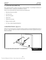
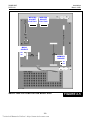
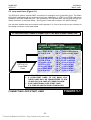
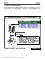
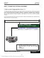
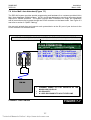
SAMSUNG
DCS-816
Installation
March 1999
7.10 Information on DCS-816 Serial Interface (Figure 7-8)
There is a variety of data terminal equipment and data communication equipment at sites and
sometimes it may be confusing how to connect the equipment to the SIO card. Generally, the
connections described in sections 7.5 to 7.7 are sufficient to work most equipment. However, the
following, more detailed information, should help if you encounter any problems.
SIO BOARD (DTE DB9)
DCD (1)
Input, Carrier Detect, Optional, Replacing DSR sometimes
RXD (2)
Input, Received Data, Essential
TXD (3)
Output, Transmitted Data, Essential
DTR (4)
Output, DTE Ready, Essential
GND (5)
Signal Ground, Reference, Essential
DSR (6)
Input, DCE Ready, Essential, Replaced with DCD sometimes
RTS (7)
Output, Request to Send, Optional
CTS (8)
Input, Clear to Send, Not Connected
RI (9)
Ring Indicator, Not Connected
INFORMATION ON SERIAL INTERFACE
FIGURE 7-8
The signal “DSR (6)” is pulled-up with a resistor in the serial interface which meets the
requirements of most data equipment. However, some printers cannot operate with the pull-up
resistor and may cause trouble. If so, DCD (1) may replace DSR (6).
For signalling protocol, all parameters can be adjusted with relevant programming (MMCs 725 and
804) and the default settings are as follows:
Serial Port 1: PCMMC
Serial Port 2 : SMDR
SIO Protocol
1 Start bit, 8 data bits, 1 Stop bit, No parity
9600 Baud rate, No DSR check, 3 times retry
7-8
Technical Manuals Online! - http://www.tech-man.com