1
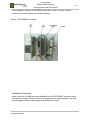
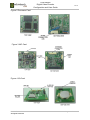
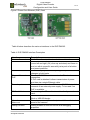
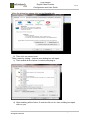
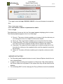
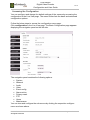
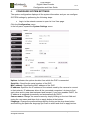
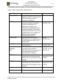
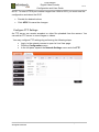
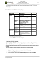
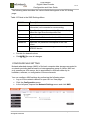
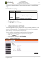
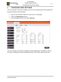
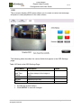
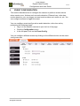
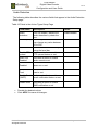
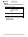
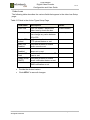
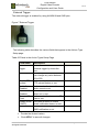
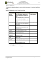
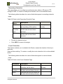
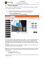
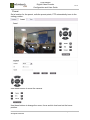
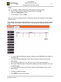
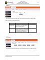
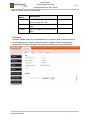
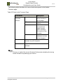
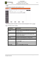
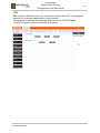
DVE-DM365 Digital Video Encoder Configuration and User Guide Revision 1.2 © 2013 RadiumBoards All Rights Reserved DVE-DM365 Digital Video Encoder Configuration and User Guide V1.2 Copyright Notice This document is copyright of RadiumBoards, All Rights Reserved. No part of this document, in whole or in part, may be used, reproduced, stored in a retrieval system or transmitted, in any form, or by any means, electronic or otherwise, including photocopying, reprinting, or recording, for any purpose, without the express written permission of RadiumBoards. Legal Disclaimer The information contained in this document is subject to change without notice. The information in this document is provided for informational purposes only. RadiumBoards specifically disclaims all warranties, express or limited, including, but not limited, to the implied warranties of merchantability and fitness for a particular purpose, except as provided for in a separate software license agreement. Radium Boards RadiumBoards is a unique website providing complete board and software solutions addressing a broad range of markets including Security and Surveillance, Networking, Wireless, Video, Audio, Automotive, Mobile Device and IoT (Internet of Things). OEMs and Systems Integrators can shop for complete assemblies, with firmware, BSP and applications ready to integrate into your own enclosures. ODMs can shop for reference designs complete with full BSP (Board Support Package) and application support. Radium Boards can also provide any level of customization to the hardware or software required by the ODM to help differentiate in their markets. Electronics hardware and software hobbyists, experimenters and educators now have access to complete high performance platforms for application in an infinite range of projects. Correspondence Corporate Office B-22, Infocity Sector-34, Gurgaon-122001, Haryana, India Tel No: +91 124 4284250 US Office 2025 Gateway Place, Suite 465 San Jose, California 95110 E-MAIL [email protected] WEBSITE www.radiumboards.com VVDN Technologies VVDN Technologies Pvt Ltd. is a sibling company of RadiumBoards and is responsible for the design and development of all products sold through the RadiumBoards brand. Founded in 2007, VVDN is a technology innovation and development company providing a broad spectrum of services and technology expertise to our core domains. VVDN provides “Concept to Customer” services at any point in the development cycle, as well as full turnkey solutions. WEBSITE www.vvdntech.com © 2013 RadiumBoards All Rights Reserved Page 2 of 62 DVE-DM365 Digital Video Encoder Configuration and User Guide 1. 2. 3. 4. 5. 6. 7. 8. 9. 10. 11. 12. V1.2 ..................................................................................... 6 ..................................................................................................................... 6 .................................................................................................... 6 ............................................................................................. 6 ............................................................................................ 7 ............................................................................ 8 .................................................................................................... 9 .................................................................................................................. 12 ........................................................................................... 13 ............................................................................................... 14 ............................................................................. 15 ..................................................................................... 15 ............................................................................................ 15 .......................................................................................... 18 ...................................................................................................................... 18 ................................................................................................. 20 ..................................................................................... 21 ........................................................................... 22 ....................................................................... 24 ............................................................................................. 26 .......................................................................................... 27 .......................................................................................... 28 ............................................................................................ 30 ........................................................................................... 31 ......................................................................................... 32 ............................................................................ 33 ............................................................................. 35 ....................................................................................................... 36 ..................................................................................................... 37 ...................................................................................................... 37 ........................................................................................................................ 38 .................................................................................... 39 ....................................................................................................... 40 ........................................................................................................... 41 ............................................................................................................... 42 ....................................................................................................... 43 ..................................................................................................... 44 ................................................................................................ 45 ....................................................................................................... 45 ..................................................................................................... 46 ................................................................................................. 47 ......................................................................................................... 48 ............................................................................................................. 49 ............................................................................................ 50 ................................................................................................................... 51 .................................................................................................................. 52 ...................................................................................................................... 53 ........................................................................................................................ 55 © 2013 RadiumBoards All Rights Reserved Page 3 of 62 DVE-DM365 Digital Video Encoder Configuration and User Guide V1.2 ........................................................................................................................ 56 13. .................................................................................................. 57 ..................................................................................................................... 57 .................................................................................................................... 58 ................................................................................................................... 58 ................................................................................................................. 59 ........................................................................................................................ 61 .......................................................................................................................... 62 Figures ................................................................................... 9 ............................................................................................ 10 ..................................................................................................... 10 ...................................................................................................... 10 ................................................................... 11 ............................................................................. 33 ........................................................................................... 43 Tables ................................................................................. 6 ................................................................................ 7 .................................................................. 8 ................................................................. 11 .............................................................. 12 ................................................................................ 13 .............................................................. 25 ................................................................ 27 .................................................. 28 ................................................ 29 .................................................................. 31 .................................................................. 32 ...................................................................................... 33 .................................................................. 34 ............................................................... 36 ............................................................. 37 .............................................................. 37 ................................................................... 38 .......................................................... 40 .......................................................... 41 .......................................................... 42 .......................................................... 43 .......................................................... 44 © 2013 RadiumBoards All Rights Reserved Page 4 of 62 DVE-DM365 Digital Video Encoder Configuration and User Guide V1.2 ......................................................... 45 ................................................................ 45 .............................................................. 46 ................................................................. 48 ..................................................................... 49 .......................................................................... 52 .............................................................................. 54 ................................................................................ 55 ............................................................................. 57 ............................................................................ 58 ........................................................................... 59 ......................................................................... 60 ................................................................................. 61 © 2013 RadiumBoards All Rights Reserved Page 5 of 62 DVE-DM365 Digital Video Encoder Configuration and User Guide 1. V1.2 ABOUT THIS DOCUMENT Purpose This document provides details of the DVE-DM365 including its features and functionality and how to install and configure the DVE-DM365. Intended Audience This document is intended for these target groups: Installation Engineers Network Administrators : It is pre-requisite to have knowledge of Wi-Fi and networking. Document Conventions The different conventions used in this document are explained in the following table: Table 1: Document Conventions Convention file/directory names © 2013 RadiumBoards All Rights Reserved Description : Provides information about important features or instructions. : Alerts you to potential damage to a program, device, or system. : Alerts you to potential injury or fatality and to potential electrical hazards. All Courier New Any option that needs to be selected or typed in the user interface is represented using bold font. Page 6 of 62 DVE-DM365 Digital Video Encoder Configuration and User Guide V1.2 Terms and Abbreviations The different terms and abbreviations used in this document are explained in Table 2 below. Table 2 Terms and Abbreviations Terms / Abbreviation ARP AVI BLC CIF CIF DHCP DNS DDNS FTP GIO HTTP HTTPS IP JPEG LED MJPEG MPEG OSD PoE PTZ RTCP RTP RTSP SD SMTP SNMP SNTP TCP/IP UDP UPnP URL VGA © 2013 RadiumBoards All Rights Reserved Description / Expansion Address Resolution Protocol Audio Video Interleave Back Light Compensation Common Intermediate Format Common International Format Dynamic Host Configuration Protocol Domain Name System Dynamic Domain Name System File Transfer Protocol General-purpose Input Output Hypertext Transfer Protocol Hypertext Transfer Protocol Secure Internet Protocol Joint Photographic Experts Group Light Emitting Diode Motion Joint Photographic Experts Group Moving Pictures Experts Group On Screen Display Power over Ethernet Pan Tilt Zoom Real-Time Transport Control Protocol Real-Time Transport Protocol Real Time Streaming Protocol Storage Device Simple Mail Transfer Protocol Simple Network Management Protocol Simple Network Time Protocol Transmission Control Protocol/Internet Protocol User Datagram Protocol Universal Plug and Play Uniform Resource Locator Video Graphics Array Page 7 of 62 DVE-DM365 Digital Video Encoder Configuration and User Guide 2. V1.2 OVERVIEW OF THE DVE-DM365 RadiumBoards DVE-DM365 enables you to quickly and cost effectively convert standard analog cameras into highly versatile IP Network cameras, which are ideal for securing locations such as small businesses, offices, shops, hotels or residences. The DVE-DM365 accepts NTSC or PAL video input from an analog camera, converts to digital and then encodes the video into high quality H.264 format which can then be streamed onto an IP Network or stored locally. DVE-365 is a modular design enabling and wide variety of connectivity, control and power options. X X DVE-L X X DVE-XL X X I/O Network DVE-Basic Model PoE Processor Table 3 DVE-DM365 Model Configurations Interfaces Audio-In, Video-In, PTZ, Iris, Ethernet Audio-In, Video-In, PTZ, Iris, Ethernet X + Power Over Ethernet (POE) X Audio-In, Video-In, PTZ, Iris, Ethernet + USB, Alarm In/Out, SD Card, UART Audio-In, Video-In, PTZ, Iris, Ethernet DVE-XXL X X X X + Power Over Ethernet (POE) + USB, Alarm In/Out, SD Card, UART © 2013 RadiumBoards All Rights Reserved Page 8 of 62 DVE-DM365 Digital Video Encoder Configuration and User Guide V1.2 The completely optioned DVE-DM365 assembly, shown in Figure 1 below, contains four boards which are stacked together. Figure 1 DVE-DM365 Assembly Hardware Overview Each of the four (4) different cards available for the DVE-DM365 is shown below and may be used for reference. Note the images are for representation only and may be slightly different depending upon build and revision. © 2013 RadiumBoards All Rights Reserved Page 9 of 62 DVE-DM365 Digital Video Encoder Configuration and User Guide V1.2 Figure 2 Processor Card Figure 3 NIC Card Figure 4 I/O Card © 2013 RadiumBoards All Rights Reserved Page 10 of 62 DVE-DM365 Digital Video Encoder Configuration and User Guide V1.2 Figure 5 Power Over Ethernet (POE) Card Table 4 below describes the various interfaces to the DVE-DM365. Table 4: DVE-DM365 Interface Description Interface Camera Connector PTZ Auto IRIS Ethernet Connector PoE Power Input SD Card Holder USB Alarm In Alarm out Debug Console © 2013 RadiumBoards All Rights Reserved Description Audio in, audio out, video in and video out interfaces The Pan / Tilt / Zoom (PTZ) menu allows users to pan (move left and right), tilt (move up and down) and zoom in and out within a specific area with just a push of a button and preset positions. Automatically adjustable iris opening in response to changes in light levels Standard RJ-45 Ethernet connector for IP network connection. If PoE card is attached it allows transmission of power and data via a single Ethernet cable. Power adapter connection. This is a +12V DC inlet, which connects to an external power supply. To be used if no PoE is available. For inserting the SD card to store data directly onto the card. USB interface can be used to connect the Wi-Fi USB Stick or USB 3G dongle Two alarm ports – input and output available on the back panel of the camera. Debug console is used for service and debugging purposes. Page 11 of 62 DVE-DM365 Digital Video Encoder Configuration and User Guide V1.2 : There is a secure digital (SD) card slot available on the right hand side of the DVE-DM365. This is used for inserting the SD card and archiving / accessing images or videos from the SD card whenever required. Features Radium’s DVE PCB suite is a modular design based on the industry leading TI DaVinci DM365 platform SoC. This 4-PCB modular design allows multiple product configurations as described in the table below. X X DVE-L X X DVE-XL X X DVE-XXL X X I/O Network DVE-Basic POE Model Processor Table 5 DVE-DM365 Module Configurations Interfaces Audio-In, Video-In, PTZ, Iris, Ethernet X X Audio-In, Video-In, PTZ, Iris, Ethernet + Power Over Ethernet (POE) X Audio-In, Video-In, PTZ, Iris, Ethernet + USB, Alarm In/OUT, SD Card, UART X Audio-In, Video-In, PTZ, Iris, Ethernet + Power Over Ethernet (POE) + USB, Alarm In/OUT, SD Card, UART The DVE-DM365 is a feature rich video platform which supports up to D1 resolution, H.264, MPEG and MJPEG compression, motion detection, privacy masking, heartbeat snapshots and much more. The design supports multiple alarm configurations and event detection. Through the USB port and appropriate 3G and Wi-Fi dongle(s), it can support 3G and Wi-Fi streaming. The device also allows you to accelerate your surveillance camera product designs especially since this design is ready and optimized for production and comes packaged with production grade software, firmware, BSP and configuration utilities. © 2013 RadiumBoards All Rights Reserved Page 12 of 62 DVE-DM365 Digital Video Encoder Configuration and User Guide V1.2 Major features of the DVE-DM365 include: TI DaVinci DM365 SoC based design Modular Design – 4 Cards Allow Multiple Configurations NTSC and PAL system support Up to D1 Res (PAL:720x576, NTSC:720x480) H264, MPEG4 and MJPEG encoding 10/100 Base-Tx Ethernet, Wi-Fi, 3G Secure RTSP, HTTP Video Motion Detection Full regular recording: SD Card, FTP and NAS PTZ Support Multiple Alarm Configurations Microphone and speaker support Supports micro SD cards up to 32GB in capacity Technical Specifications The following table provides the technical specification of the DVE-DM365: Table 6 Technical Specifications Image Sensor 720 TVL max System PAL/NTSC Audio Compression G711 , AAC Vol. 0 - 15 Talk back 2-way Audio – Video Compression H264 , MPEG4 , MJPEG Resolution D1, 4CIF, CIF, QCIF, VGA, QVGA Frame Rate NTSC: 5-30 FPS, PAL: 5-25 FPS Bit Rate 64 Kbps-5 Mbps Video Streaming Simultaneous H.264, MPEG4 and MJPEG Streams. Configurable Frame rate and rate control(VBR/CBR) Image settings Compression, Brightness, Contrast, Saturation, Sharpness, HUE, Auto DC Iris Profile Schedule 5 Different Video Profiles, Schedule different video profiles for day and night time Network Interface 10/100 RJ-45 Base-TX Ethernet, 3G Wi-Fi Security Password Protection: Secure RTSP, Secure HTTP E-Mail and SMS Support Full E-mail and SMS support, Test E-mail and SMS Settings Supported Protocol IPv4, HTTP, HTTPS, SNTP,FTP, SMTP, DNS, DDNS, RTSP, RTP, TCP, UDP, IGMP, RTCP, ICMP, DHCP, UPNP, PPPoE, NAS © 2013 RadiumBoards All Rights Reserved Page 13 of 62 DVE-DM365 Digital Video Encoder Configuration and User Guide V1.2 Multicast Support Available Regular Recording Full regular recording on SD card, FTP and NAS storage Intelligent Video Video motion detection, Privacy masking, Heart Beat Snapshots Events Audio Detection, Video and Network Loss, Motion Detection, External Trigger Alarm Action FTP recording, SD Card recording with pre-post support, Alarm Out Trigger, Audio alarm out with 5 audio files, NAS Storage, SMS, E-Mail OSD Date , Time , Camera Name , Frame rate , Bit rate 3G Support CDMA - Ix , EVDO , GSM-Edge , GPRS, HSPDA , HSPA+ * *Dependent on the data card Wi-Fi Support 802.11 a,b,g,n * *Dependent on the Wi-Fi Dongle PTZ Support Pan, Tilt, Zoom, Focus 0 - 255 different Presets and Tours User Set 9 different users set with Different Privileges Live View Zoom Zoom in and Zoom out up-to 4x Snapshot Local System Snapshot Video Record Local Video Record Logging Full System and event logs. System Requirements The DVE-DM365 may be configured from any PC that is on the same network. The minimum requirements include: Operating system: Microsoft Windows 2000, XP, Vista or Windows 7 Browser: Internet Explorer 6.x with Service Pack 2 or later Minimum of 200 MHz processor 128MB RAM (recommended) Cat5e Ethernet network cable © 2013 RadiumBoards All Rights Reserved Page 14 of 62 DVE-DM365 Digital Video Encoder Configuration and User Guide 3. V1.2 INSTALLING THE DVE-DM365 Connecting the DVE-DM365 After completing assembly of the DVE-DM365 you may perform the following steps to connect power and network to the camera. DC Adapter: Connect the power adaptor plug into the power supply jack and then plug the adapter into a power source. Connect an Ethernet cable from the Ethernet port into the PC. PoE Adapter: Insert one end of an Ethernet cable into the port in the PC and other end into the PoE adapter. Connect another cable from the PoE port on the adapter to the camera’s port. PoE Switch: Insert one end of an Ethernet cable into the PoE switch and other end into the camera. Connect another cable from the PC into the PoE switch. Optionally connect external input/output alarm devices. Connect the cables of the alarm device securely to the supplied alarm I/O terminal block. Attach the terminal block to the I/O terminal connector on the camera. : Please use the power adapter supplied with the DVE-DM365. Using a power adapter with a different voltage rating can damage this product. Assigning an IP Address After the DVE-DM365 is installed at an appropriate location you will need to configure its IP address. The camera is configured through an Ethernet connection. Ensure that the system is set on the same IP subnet address. For example, if the default IP address of the camera is 192.168.1.168, then the system should be set at 192.168.1.1 to 192.168.1.254 (excluding the camera’s IP address 192.168.1.168) and the default subnet mask is 255.255.255.0. © 2013 RadiumBoards All Rights Reserved Page 15 of 62 DVE-DM365 Digital Video Encoder Configuration and User Guide V1.2 Perform the following steps to configure the IP address: Go to desktop, right-click , and select Right-click and select . . The Local Area Connection Properties dialog box appears. © 2013 RadiumBoards All Rights Reserved Page 16 of 62 DVE-DM365 Digital Video Encoder Configuration and User Guide Select the checkbox and click The Internet Protocol (TCP/IP) Properties dialog box appears. V1.2 . Click . Set the IP address to 192.168.1.x and subnet mask to 255.255.255.0, where x is a number between 2 and 254, except 168. Click to close all windows. This connects the camera to the network. You can now configure and change the default settings of the camera as explained in the subsequent chapters. : If assigning the IP address fails, check that there is no firewall blocking the operation. © 2013 RadiumBoards All Rights Reserved Page 17 of 62 DVE-DM365 Digital Video Encoder Configuration and User Guide 4. V1.2 ACCESSING THE GUI This chapter explains how to access the DVE-DM365 through a web browser. The DVE-DM365 is functional with the default settings, but you can configure and change these settings through the GUI Log In You can connect to the camera by performing the following steps: Enter the http://192.168.1.168URL in the web browser as shown below to access the GUI. If the Active X is not installed then it shows an add-on for this website failed to run. Perform the following steps to enable the Active X control: a) Click on tools in the menu bar then click on internet options. © 2013 RadiumBoards All Rights Reserved Page 18 of 62 DVE-DM365 Digital Video Encoder Configuration and User Guide V1.2 When the dialog box opens, click on the Security tab. b) Then click on custom level. Then a security setting – internet zone dialog box will open, c) Then enable all the Active X controls and plug-in. d) After enabling all the Active X controls click on ok .then a dialog box open, click on yes. © 2013 RadiumBoards All Rights Reserved Page 19 of 62 DVE-DM365 Digital Video Encoder Configuration and User Guide V1.2 Then again enter the http://192.168.1.168URL in the web browser to access the GUI. Then a login page opens. Enter user name as admin and password as admin. Click on login. The default page (known as the Live View page) appears displaying the live video. The following options appear in the Live View page: 1) Zoom in: The zoom in button enables you to zoom in the live video as you can enlarge the view of an object to show more details. 2) Zoom out: The zoom buttons enables you to zoom from the live video. 3) Video Recording: The video recording button enables you to record the live video in the local computer and the video is saved in My Videos. 4) Snap shot: The snap shot button enable you to take the snap shot of the live video by clicking on the snapshot button and the snapshot is saved in My Pictures. 5) Alarm off: The alarm off button enables you to stop the continuous audio out. IMPORTANT NOTES: For Recording and Snapshot buttons to work, Internet Explorer should be run as an Administrator. In case of video recording and snapshot on Client side, if My Videos and the My Picture folder are not present in the system then they will be stored on the desktop. For accessing HELP on the web page the Pop up Blocker should be disabled. © 2013 RadiumBoards All Rights Reserved Page 20 of 62 DVE-DM365 Digital Video Encoder Configuration and User Guide V1.2 Accessing the Configuration You can configure and change the default settings of the camera by accessing the configuration in the Live View page. The menu further lists the basic and advanced configuration options. Follow the below steps to access the configuration menu page: Click configuration in the Live View page. The Basic Configuration page appears displaying the navigation panel on the left side. The navigation panel contains the following options: System Network Audio Video Event-config Alarm-action Privacy-mask PTZ Users Maintenance You can view and configure the sub-menus by clicking the respective configure menu as shown above. © 2013 RadiumBoards All Rights Reserved Page 21 of 62 DVE-DM365 Digital Video Encoder Configuration and User Guide 5. V1.2 CONFIGURE SYSTEM SETTINGS The system configuration displays all the system information and you can configure SYSTEM settings by performing the following steps: Log in to the network camera to open its Live View page. Click the Configuration menu. In the left pane, expand the System Settings menu. Uptime: Indicates the uptime duration from which the DVE is connected. Serial No.: Specifies the serial number of the DVE. MAC address: Specifies the MAC address of the DVE. IP address: Specifies the IP address of the network used by the camera to connect to that network. IP addresses allow all the connected computers / devices to find each other and to pass data backward and forward. If you have enabled DHCP, the IP address is assigned dynamically and automatically by DHCP. Camera name: Change the camera name by simply clicking on the text field and typing the new name and then click on apply button at the bottom. Language: Change the preferred language by clicking on the drop down button and selecting the particular language you want to select and click on apply button. © 2013 RadiumBoards All Rights Reserved Page 22 of 62 DVE-DM365 Digital Video Encoder Configuration and User Guide V1.2 Configure Date and Time Settings Customize the date and time format to suit your needs while configuring system settings. It allows the GUI and email alerts to set time and date according to the user-defined date and time. a) Set manually: Manually set the date and time by clicking on the field and set the date and time then click on apply. b) SNTP: Specifies the SNTP server URL address configured in the SNTP Server Setting page. c) Sync with PC: Synchronize the date and time of the DVE with your computer. © 2013 RadiumBoards All Rights Reserved Page 23 of 62 DVE-DM365 Digital Video Encoder Configuration and User Guide 6. V1.2 CONFIGURE NETWORK SETTINGS The network settings allow you to assign an IP address to the camera. This can be done either manually or automatically from a dynamic host configuration protocol (DHCP) server. If you are not using DHCP, provide the IP address, subnet mask, and default gateway of the camera. If you enable DHCP, a DHCP request is sent when the camera is turned on. By default static addressing is enabled. You can configure NETWORK settings by performing the following steps: Log on to the network camera to open its Live View page. Click the Configuration menu. In the left pane, click on the Network Settings menu. © 2013 RadiumBoards All Rights Reserved Page 24 of 62 DVE-DM365 Digital Video Encoder Configuration and User Guide V1.2 The following table describes the various fields that appear in the Network page: Table 7 Fields in the Network Settings Menu Field Name Enable DHCP IP Address Subnet mask Default Gateway Primary and secondary DNS HTTP Port HTTPS Port Description Indicates that you can enable or disable the DHCP. DHCP supports static addressing through a permanent IP address. Specifies the IP address of the network used by the camera to connect to that network. IP addresses and allow all the connected computers/devices to find each other and to pass data backward and forward. If you have enabled DHCP, the IP address is assigned dynamically and automatically by DHCP. Specifies the subnet mask or routing prefix of an address written in a form identical to that of the address itself. Specifies the address of the default gateway. Specifies the primary and secondary server used for information about a domain as well as the location of resources associated with a domain. Specifies the communications endpoint for the uniform resource locator (URL) of a website or other services. Specifies the communications endpoint for the uniform resource locator (URL) of a website or other services. Values - Default: 192.168.1.168 Default: 255.255.255.0 Default: 192.168.1.254 Default: 192.168.1.1 and 192.168.1.3 Default: 80 Range from 1024 – 65536 Default: 81 Range from 1024 – 65536 UPnP Multicast © 2013 RadiumBoards All Rights Reserved Page 25 of 62 DVE-DM365 Digital Video Encoder Configuration and User Guide V1.2 NOTE: To enter HTTPS port number ranges from 1024 to 6553, you must save the configuration and reboot the DVE. Provide the desired values. Click APPLY to save the changes. Configure FTP Settings An FTP server can receive snapshot or video file uploaded from the camera. You can add an FTP server to store images or videos. You may configure FTP settings by performing the following steps: Log in to the network camera to open its Live View page. Click the Configuration menu. In the left pane, expand the Network Settings menu and click FTP © 2013 RadiumBoards All Rights Reserved Page 26 of 62 DVE-DM365 Digital Video Encoder Configuration and User Guide V1.2 The following table describes the various fields that appear in the FTP Server Setup page: Table 8 Fields in the FTP Server Setup Page Field Name FTP Name Server Network Address Upload Path Description Specifies the name of the FTP server. Specifies the host name or IP address of the FTP server. Specifies the upload path of the FTP server. Avoid special characters, for example “,<,>,%. Specifies the port number of the FTP server. Specifies the file format. Port Number File Format Login User Specifies the user name. Information Name Password Specifies the password corresponding to the user name. Values - - AVI - Provide the desired values. Click APPLY to save all changes. Configure DDNS Settings Dynamic DNS or DDNS is a method of updating, in real time, a Domain Name System (DNS) to point to a changing IP address on the Internet. This is used to provide a persistent domain name for a resource that may change location on the network. You can configure DDNS settings by performing the following steps: Log on to the network camera to open its Live View page. Click the configuration menu. In the left pane, expand the network Settings menu and click DDNS. © 2013 RadiumBoards All Rights Reserved Page 27 of 62 DVE-DM365 Digital Video Encoder Configuration and User Guide V1.2 The following table describes the various fields that appear in the DDNS Setting page: Table 9 Fields in the DDNS Application Setting Page Field Name Description DDNS Enable or disable the DDNS by check the box Specifies the DDNS service provider Specifies URL provided by the DDNS service provider. Specifies the username Specifies the password correspond to the username. Provider Host name User name password Provide the desired values. Click to save all changes. Configure SMTP Settings You can enable sending of emails and notifications from the camera to predefined addresses through SMTP. You can configure SMTP settings by performing the following steps: Log on to the network camera to open its Live View page. Click the configuration menu. In the left pane, expand the network Settings menu and click SMTP. © 2013 RadiumBoards All Rights Reserved Page 28 of 62 DVE-DM365 Digital Video Encoder Configuration and User Guide V1.2 The following table describes the various fields that appear in the SMTP server and mail Settings page: Table 10 Fields in the SMTP Application Settings Page Field Name Description Login method Specifies the login method for sending mails, whether form user account or from anonymous. Specifies the SMTP server from where the mail is to be sent. Specifies the port number of the SMTP server. Specifies the username. Specifies the password correspond to the username. Specifies the Email ID from where the mail is to be sent. Specifies the Email IDs to whom the mail is to be sent. Specifies the prefix like: Subject:<prefix>_<alarm>_<event>_<timestamp> SMTP server Port Username Password Mail from Mail to Subject prefix © 2013 RadiumBoards All Rights Reserved Page 29 of 62 DVE-DM365 Digital Video Encoder Configuration and User Guide V1.2 Provide the desired values. Click to save all changes. Configure SMS Settings You can enable sending of SMS and notifications from the camera to predefined mobile number through SMS.You can configure SMS settings by performing the following steps: Log on to the network camera to open its Live View page. Click the Configuration menu. In the left pane, expand the Network Settings menu and click SMS . © 2013 RadiumBoards All Rights Reserved Page 30 of 62 DVE-DM365 Digital Video Encoder Configuration and User Guide V1.2 The following table describes the various fields that appear in the SMS server and Setting page: Table 11 Fields in the SMS Settings Menu Field Name Username Password Service Api Description Specifies the username Specifies the password correspond to the username Specifies the following http://sms.foosms.com/pushsms.php?username= |USERNAME|&password=|PWD|&sender= |DVE|&to=|TO|&message=|MESSAGE| Mobile No. Specifies the mobile no to which the SMS is to be sent. Message prefix Subject:<prefix>_<alarm>_<event>_<timestamp> Provide the desired values. Click APPLY to save all changes. CONFIGURE 3G SETTING You can configure 3G settings by performing the following steps: Log on to the network camera to open its Live View page. Click the Configuration menu. In the left pane, expand the Network Settings menu and click 3G. © 2013 RadiumBoards All Rights Reserved Page 31 of 62 DVE-DM365 Digital Video Encoder Configuration and User Guide V1.2 The following table describes the various fields that appear in the 3G Setting page: Table 12 Fields in the SMS Settings Menu Field Name Description Status Specifies the status of the 3G weather it is connected, not connected or reconnecting. Specifies the type of connectivity (Manual or Auto), select the type from the drop down list. Specifies the APN for the different devices. - Specifies the Dial number for the different devices. Specifies the user name for the particular device. Specifies the password correspond to the user name Specifies the IP Address assign to the DVE by the USB 3G device. Type APN Dial number Username Password IP Address Provide the desired values. Click to save all changes. CONFIGURE NAS SETTING Network-attached storage (NAS) is file-level computer data storage connected to a network providing data access to a heterogeneous group of clients. NAS not only operates as a file server, but is specialized for this task either by its hardware, software, or configuration of those elements You can configure NAS settings by performing the following steps: Log on to the network camera to open its Live View page. Click the Configuration menu. In the left pane, expand the Network Settings menu and click NAS. © 2013 RadiumBoards All Rights Reserved Page 32 of 62 DVE-DM365 Digital Video Encoder Configuration and User Guide V1.2 The following table describes the various fields that appear in the NAS Setting page: Table 13 NAS Settings Page Field Name Description NAS enable Enable or disable the NAS by check or uncheck the box Specifies the network storage location as server name or server IP followed by directory to be mounted. For e.g. <ip-address>:/mount directory Network Storage Location 7. Provide the desired values. Click to save all changes. CONFIGURE AUDIO SETTINGS This section describes how to configure and turning the audio mechanism of the camera on/off automatically. IP camera plays a built-in sound file on local site when alarming, and the volume is controlled here. You can configure audio settings by performing the following steps: Log on to the network camera to open its Live View page. Click the menu. In the left pane, expand the Audio . Figure 6: The Audio Settings Page © 2013 RadiumBoards All Rights Reserved Page 33 of 62 DVE-DM365 Digital Video Encoder Configuration and User Guide V1.2 The following table describes the various fields that appear in the Audio Setting page. Table 14 Fields in the Audio Setting Page Field Name Audio Enable Input volume Encoding Sample rate Bit rate Output volume Description Specifies whether the camera audio is enable or not. Values ON/OFF Specifies the input sound volume range Specifies the encoding format of AAC-LC / G711 the audio. Specifies the sample rate for the 8KHz / 16KHz audio. Specifies the bit rate of the audio. Auto / 32Kbps Specifies the output sound volume range. Provide the desired values. Click to save all changes. © 2013 RadiumBoards All Rights Reserved Page 34 of 62 DVE-DM365 Digital Video Encoder Configuration and User Guide 8. V1.2 CONFIGURE VIDEO SETTINGS You can configure the video settings such as video encoding and video parameters by performing the following steps: Log on to the network camera to open its Live View page. Click the Configuration menu. In the left pane, click on the video Settings. You can configure the video encoding and video parameters and OSD by click on the video encoding and video parameters button in the video setting menu bar. © 2013 RadiumBoards All Rights Reserved Page 35 of 62 DVE-DM365 Digital Video Encoder Configuration and User Guide V1.2 Video Encoding The following table describes the various fields that appear in the video encoding page: Table 15 Fields in the Video Encoding Page Field Name Video mode Description Specifies the type of video mode Video Specifies the video system system format Video profile Specifies the different profile for different video stream Streams Specifies thee different stream which can be enable / disable. Compression Specifies the different compression level which affects the amount of bandwidth required. Resolution Specifies the different resolution for the video. FPS Specifies the different frequency for the image. Rate control You can choose constant code stream(CBR) or variable code stream(VBR) Bit rate Specifies the no of bits that can be processed per unit time. Audio You can enable or disable the audio for the particular stream Values Auto/ manual NTSC / PAL Profile 1 to profile 5 Primary, Secondary , Mobile H264/MJPEG/ MPEG4. Stream resolution 5 to 25 CBR/VBR 64Kbps to 5Mbps Provide the desired values. Click APPLY to save all changes. © 2013 RadiumBoards All Rights Reserved Page 36 of 62 DVE-DM365 Digital Video Encoder Configuration and User Guide V1.2 Video Parameters The following table describes the various fields that appear in the video parameters page: Table 16 Fields in the video parameters Page Field Name Iris level Mirroring Description Values Use the iris bar for increase or decrease the iris level. Specifies the type of Horizontal, vertical, both. mirroring. Provide the desired values. Click APPLY to save all changes. Profile Scheduler The following table describes the various fields that appear in the Profile Scheduler page: Table 17 Fields in the Profile Scheduler Page Field Name Day start/end time Holiday Day time video profile Night time video profile Description Specifies start and end time for particular set video profile, rest of the time will be considered as night time Specifies two holidays, on holiday night profile will run Select any video profile for day time Select any video profile for night time Values Provide the desired values. Click APPLY to save all changes. © 2013 RadiumBoards All Rights Reserved Page 37 of 62 DVE-DM365 Digital Video Encoder Configuration and User Guide V1.2 OSD The on-screen display (OSD) option allows you to create a custom text message and place it nearly anywhere on the video screen. The following table describes the various fields that appear in the OSD Settings page: Table 18 Fields in the OSD Settings Page Field Name Enable Date and Time Stamp Camera name Bit rate FPS Description Indicates whether to insert the date and time stamp in the image or video. Indicate the camera name Indicate the bit rate Indicate the frame per sec . Values - Provide the desired values. Clicks APPLY to save all changes. © 2013 RadiumBoards All Rights Reserved Page 38 of 62 DVE-DM365 Digital Video Encoder Configuration and User Guide 9. V1.2 EVENT CONFIGURATION This section describes how to configure the camera to perform certain actions when events occur. Actions such as audio detection, Ethernet loss, video loss, motion detection, etc. can trigger an event such as alarm out, audio out, etc. You can configure actions to trigger the event. You can configure event config such as audio detection, video loss etc by performing the following steps: Log on to the network camera to open its Live View page. Click the Configuration menu. In the left pane, click on the Event-Config. You can configure different events by clicking on the different button on the eventconfig menu bar. © 2013 RadiumBoards All Rights Reserved Page 39 of 62 DVE-DM365 Digital Video Encoder Configuration and User Guide V1.2 Audio Detection The following table describes the various fields that appear in the Audio Detection Setup page: Table 19 Fields in the Action Types Setup Page Field Name Audio detection Enable FTP upload Audio Out Enabled Alarm Out Enabled Description You can enable / disable the audio detection by check the box. You can just click the box and can change any value between 10 to 200. The alarm level can be set by using the level bar. Indicates whether to enable FTP upload feature or not. Indicates whether to enable audio sound or not. Indicates whether to enable alarm out or not. Save to SD Card Enable Email (SMTP) Indicates whether to save to SD card or not. Indicates whether to enable email notification feature or not. Enable SMS Indicates whether to enable SMS notification or not. Interval (sec) Alarm level Values Enable/disable 10 - 200 Provide the desired values. Click APPLY to save all changes. © 2013 RadiumBoards All Rights Reserved Page 40 of 62 DVE-DM365 Digital Video Encoder Configuration and User Guide V1.2 Network Loss The following table describes the various fields that appear in the Network loss Setup page: Table 20 Fields in the Action Types Setup Page Field Name Network loss Interval (sec) Alarm level Save to SD Card Audio Out Enabled Alarm Out Enabled Description You can enable / disable the network loss by check the box. You can just click the box and can change any value between 10 to 200. The alarm level can be set by using the level bar. Indicates whether to save to SD card or not. Indicates whether to enable audio sound or not. Indicates whether to enable alarm out or not. Values Enable/disable 10 - 200 Provide the desired values. Click APPLY to save all changes. © 2013 RadiumBoards All Rights Reserved Page 41 of 62 DVE-DM365 Digital Video Encoder Configuration and User Guide V1.2 Video Loss The following table describes the various fields that appear in the video loss Setup page: Table 21 Fields in the Action Types Setup Page Field Name Video loss Interval (sec) Enable FTP upload Audio Out Enabled Alarm Out Enabled Save to SD Card Enable Email (SMTP) Enable SMS Description You can enable / disable the video loss by check the box. You can just click the box and can change any value between 10 to 200. Indicates whether to enable FTP upload feature or not. Indicates whether to enable audio sound or not. Indicates whether to enable alarm out or not. Indicates whether to save to SD card or not. Indicates whether to enable email notification feature or not. Indicates whether to enable SMS notification or not. Values Enable/disable (10 -200) Provide the desired values. Click APPLY to save all changes. © 2013 RadiumBoards All Rights Reserved Page 42 of 62 DVE-DM365 Digital Video Encoder Configuration and User Guide V1.2 External Trigger The external trigger is enabled by using ALARM IN and GND pins. Figure 7 External Trigger The following table describes the various fields that appear in the Actions Type Setup page: Table 22 Fields in the Action Types Setup Page Field Name External trigger Interval (sec) Enable FTP upload Audio Out Enabled Alarm Out Enabled Save to SD Card Enable Email (SMTP) Enable SMS Description You can enable / disable the external trigger by check the box. You can just click the box and can change any value between 10 to 200. Indicates whether to enable FTP upload feature or not. Indicates whether to enable audio sound or not. Indicates whether to enable alarm out or not. Indicates whether to save to SD card or not. Indicates whether to enable email notification feature or not. Indicates whether to enable SMS notification or not. Values Enable/disable (10 -200) Provide the desired values. Click APPLY to save all changes. © 2013 RadiumBoards All Rights Reserved Page 43 of 62 DVE-DM365 Digital Video Encoder Configuration and User Guide V1.2 Motion Detection The following table describes the various fields that appear in the video loss Setup page: Table 23 Fields in the Action Types Setup Page Field Name Motion detection Interval (sec) Sensitivity Enable FTP upload Audio Out Enabled Alarm Out Enabled Save to SD Card Enable Email (SMTP) Enable SMS Description You can enable / disable the motion detection by check the box. You can select all or remove all windows by selecting the appropriate radio button on the panel. You can just click the box and can change any value between 10 to 200. The detection sensitivity can be adjusted by selecting from the sensitivity bar. Indicates whether to enable FTP upload feature or not. Indicates whether to enable audio sound or not. Indicates whether to enable alarm out or not. Indicates whether to save to SD card or not. Indicates whether to enable email notification feature or not. Indicates whether to enable SMS notification or not. Values Enable/disable (10 -200) Provide the desired values. Click APPLY to save all changes. © 2013 RadiumBoards All Rights Reserved Page 44 of 62 DVE-DM365 Digital Video Encoder Configuration and User Guide V1.2 Recording Scheduler This page allows you to configure to continuous save video to SD card or FTP storage or NAS. To create or modify the scheduler click on the add/edit button. The following table describes the various fields that appear in recording schedule page: Table 24 Fields in the Recording Schedule Page Field Name Days Start time/End time Status Description Specify the days of the week the recording will be active Specifies the hour and minute for the start and end times (hh:mm). Specifies the hour and minute for the start and end times (hh:mm). Values Monday to Sunday Provide the desired values. Click APPLY to save all changes. Event Scheduler This feature enables you to schedule the Events, means the duration of the day a particular Alarm will be enabling. To create or modify the event scheduler click on the add/edit button. The following table describes the various fields that appear in event schedule page: Table 25 Fields in the Event Schedule Page Field Name Days Start time End time Status © 2013 RadiumBoards All Rights Reserved Description Specify the days of the week the recording will be active Specifies the hour and minute for the start and end times (hh:mm). Specifies the hour and minute for the start and end times (hh:mm). Values Monday to Sunday Page 45 of 62 DVE-DM365 Digital Video Encoder Configuration and User Guide V1.2 Provide the desired values. Click APPLY to save all changes. Heartbeat Images Keep alive mechanism to ensure camera operation and up time. The following table describes the various fields that appear in heartbeat image page: Table 26 Fields in the Heartbeat Image Page Field Name Snapshot Snapshot duration Snapshot interval No. of snapshot ACTION Save to SD Card Enable Email (SMTP) Enable FTP upload Description you can enable/disable the camera to capture snapshot at regular interval Specifies the time interval between each snapshot. Specifies the interval at which the snapshot is to be taken Specifies the number of snapshot to be taken at occurrence tim Values 1 – 60 min 10 -60 sec Indicates whether to save to SD card or not. Indicates whether to enable email notification feature or not. Indicates whether to enable FTP upload feature or not. Provide the desired values. Click APPLY to save all changes. © 2013 RadiumBoards All Rights Reserved Page 46 of 62 DVE-DM365 Digital Video Encoder Configuration and User Guide 10. V1.2 ALARM ACTION You can configure alarm action such as media storage and notification by performing the following steps: Log on to the network camera to open its Live View page. Click the Configuration menu. In the left pane, click on the Alarm Action. You can configure the media storage and notification by clicking on button in the alarm action menu bar. © 2013 RadiumBoards All Rights Reserved Page 47 of 62 DVE-DM365 Digital Video Encoder Configuration and User Guide V1.2 Media Storage The following table describes the various fields that appear in media storage page: Table 27 Fields in the Media Storage Page Field Name Pre/Post – Recording (sec) SD File list SD File overwrite SD card full alarm ACTION Enable Email (SMTP) Enable SMS Status Description The pre/post recording can be enable or disable by check/clear the box. Pre/Post alarm video recording durationis selected from the drop-down list. Specifies the files lists in the SD card Enables you to overwrite the file in the SD card. Configure alarm for SD card full status , you can select the diff level Values Pre recording 13 sec Post 30-90 % Indicates whether to enable email notification feature or not Indicates whether to enable SMS notification or not. Specifies the status of the SD card Provide the desired values. Click APPLY to save all changes. © 2013 RadiumBoards All Rights Reserved Page 48 of 62 DVE-DM365 Digital Video Encoder Configuration and User Guide V1.2 Notification The following table describes the various fields that appear in media notification page Table 28 Fields in the Notification Page Field Name Audio file Test Repeat Alarm out (sec) Description Specifies the audio file which will play at the time of audio out. Play the selected audio file Audio1 to audio5 It can be used to add Repetition cycle for the audio file (0) means continues. Specifies the duration of the alarm out 5 to 120 FTP upload Specifies the file type to be format uploaded Values Image/ Video Provide the desired values. Click APPLY to save all changes. © 2013 RadiumBoards All Rights Reserved Page 49 of 62 DVE-DM365 Digital Video Encoder Configuration and User Guide 11. V1.2 PRIVACY MASKING Privacy masks are configurable areas of solid color that allow concealment of parts of the image that should not be viewable. You can configure Privacy masking by performing the following steps: Log on to the network camera to open its Live View page. Click the Configuration menu. In the left pane, click on the Privacy Masking. User can mask the video by clicking any of the (PW 1 -4) button windows shown on the snapshot frame window where the user can resize , drag , overlap the privacy masking windows After pressing apply button the privacy mask windows are set on the encoder and all the streams from the camera start showing the privacy masking windows. The privacy masking zones in the windows can support up to 4 zones only, that can be resized/overlap to a particular dimension. Remove: To remove the particular privacy mask zone by selecting it from the button panel and click on remove button and to remove all the privacy masked zones click on remove all. Provide the desired values. Click APPLY to save all changes. © 2013 RadiumBoards All Rights Reserved Page 50 of 62 DVE-DM365 Digital Video Encoder Configuration and User Guide 12. V1.2 PTZ The Pan / Tilt / Zoom (PTZ) menu allows users to pan(move left and right), tilt (move up and down), and zoom in and out a specific area with just a push of a button and preset positions. You can configure Pan/Tilt/Zoom settings by performing the following steps: Log on to the network camera to open its Live View page. Click the Configuration menu. In the left pane, click on PTZ. © 2013 RadiumBoards All Rights Reserved Page 51 of 62 DVE-DM365 Digital Video Encoder Configuration and User Guide V1.2 Protocol The following table describes the various fields that appear in PTZ protocol page. Table 29 Fields in the Protocol Page Field Description Name PTZ enable User can enable / disable the PTZ control. Protocol Specifies the corresponding dome protocol Address Specifies the corresponding dome address Baud rate Specifies the corresponding dome baud rate length. Speed Specifies the corresponding dome movement speed Data , stop Specifies the data , stop and , parity bit parity bit Values Pelco P, Pelco D Default 1 (1 to 255) 1200, 2400, 4800, 9600 1 to 8 Stop bit 1-2 Data bit 7-8 Parity bit (none, odd ,even) Default Set the default PTZ controls Provide the desired values. Click APPLY to save all changes. NOTE: For Custom protocol settings open the following URL: http://<ip-address>/maintenance/cptz.html © 2013 RadiumBoards All Rights Reserved Page 52 of 62 DVE-DM365 Digital Video Encoder Configuration and User Guide V1.2 Preset Set a location for the preset, calls the preset points, PTZ automatically turns to the setting position. Use these buttons to move the camera. Use these buttons to change the zoom, focus and iris level and set the home position. © 2013 RadiumBoards All Rights Reserved Page 53 of 62 DVE-DM365 Digital Video Encoder Configuration and User Guide V1.2 The following table describes the various fields that appear in PTZ preset page Table 30 Fields in the Preset Page Field Name Preset ID Name Go Save Delete © 2013 RadiumBoards All Rights Reserved Description Specifies a pre-defined camera view that can be quickly and easily viewed in the Live View page, simply by selecting the preset's name from the dropdown list. You can set the different location for the preset position. The ID is corresponding to the preset position you have selected. You can specify the name corresponding to preset position. Use this button to run the camera to the preset location Use this button to save the preset location Use this button to delete the existing preset location Values There are 255 different preset location . Same as preset location Page 54 of 62 DVE-DM365 Digital Video Encoder Configuration and User Guide V1.2 Tour Tour means that the selective channel is single window alternate patrol preview. The following table describes the various fields that appear in PTZ tour page Table 31 Fields in the Tour Page Field Name Tour Name Preset (15) Go Save Delete Stop © 2013 RadiumBoards All Rights Reserved Description Specifies the different tour that you can select, edit and configure the tour. Specifies the name correspond to the selected tour. Values There are 8 different tour. Specifies the 5 different preset positions for the single tour. you can set 5 different positions. Use this button to run the tour Use this button to save the tour Use this button to delete the existing tour Use this button to stop the running tour. Page 55 of 62 DVE-DM365 Digital Video Encoder Configuration and User Guide V1.2 User You can configure USER settings by performing the following steps: Log in to the network camera to open its Live View page. Click the Configuration menu. In the left pane, click on User. The user account settings include configuring usernames/ passwords and adding/ deleting users. There will be 10 user accounts by default, but only one user can access the camera at the initially that is admin, and then admin can change the settings related to the users. You may add nine different users by clicking on the Add New button shown in the above fig. You may set the privilege by check the box that you want to give access permission. If no check box selected, user will have only “Video view permission”. Once you added the user, if required to modify you have to delete it first and re-add the user. You may delete the user account by using the delete button shown in the above figure. Provide the desired values. Click APPLY to save all changes. © 2013 RadiumBoards All Rights Reserved Page 56 of 62 DVE-DM365 Digital Video Encoder Configuration and User Guide 13. V1.2 MAINTENANCE You can configure maintenance settings by performing the following steps: Log on to the network camera to open its Live View page. Click the Configuration menu. In the left pane, click on Maintenance. Config The following table describes the various fields that appear in config page Table 32 Fields in the Config Page Field Name Save Download Restore Upload Delete © 2013 RadiumBoards All Rights Reserved Description Values Use this button to save the current configuration setting Use this button to download the current configuration setting as .cfg format at default location. Use this button to restore all the settings to the factory default values, meaning that the unit must be reconfigured and any event types and PTZ presets must be recreated Use this button to upload any saved configuration by selecting from the desired location Use this button to delete the selected configuration setting Page 57 of 62 DVE-DM365 Digital Video Encoder Configuration and User Guide V1.2 Reboot The following table describes the various fields that appear in reboot page Table 33 Fields in the Reboot Page Field Name Description Select Specifies the configuration that configuration you want to select and reboot with that configuration. Reboot Use this button to perform a correct restart of the DVE with the selected configuration , if it is not behaving as expected Values SD Card The following table describes the various fields that appear in SD card page. © 2013 RadiumBoards All Rights Reserved Page 58 of 62 DVE-DM365 Digital Video Encoder Configuration and User Guide V1.2 Table 34 Fields in the SD Card Page Field Name Remove Mount Format Description Values Use this button to remove/ unmount the SD card. Use this button to mount the SD card. Use this button to format the SD card. Firmware Firmware update refers to the replacement of a product with a newer version of the same product in order to keep the system updated. When upgrading the camera with the latest firmware, the camera receives the latest functionality. © 2013 RadiumBoards All Rights Reserved Page 59 of 62 DVE-DM365 Digital Video Encoder Configuration and User Guide V1.2 The following table describes the various fields that appear in the Update Firmware page: Table 35 Fields in the Firmware Page Field Name Current firmware version Browse Update Description Kernel Version Specifies the kernel version of the firmware. UBL version Specifies the UBL version. U-Boot Version Specifies the universal boot loader version which initializes the version of the firmware. Hardware revision Specifies the hardware revision of the firmware. Enables to navigate and select the firmware on your computer. Upgrades the camera with the latest firmware. : Ensure you upload the correct firmware file because uploading the wrong model firmware may damage your device. © 2013 RadiumBoards All Rights Reserved Page 60 of 62 DVE-DM365 Digital Video Encoder Configuration and User Guide V1.2 Logs Logs provide information about system events. The following table describes the various fields that appear in the Log page: Table 36 Fields in the Log Page Field Name All/System/Event Search Download Item Date and Time Events First Page Previous Next Final page © 2013 RadiumBoards All Rights Reserved Description You can select the event type you want to see. You can search for any particular log corresponds to string entered. Use this button to download logs to the computer. Specifies the serial number of the events or all access to the camera. Specifies the date and time of a specific event. Specifies a brief description of each event. Specifies the first page with latest 20 events. Specifies the previous 20 events to get to the previous page. Specifies the next 20 events to move to the next page. Show the last page of the logs. Page 61 of 62 DVE-DM365 Digital Video Encoder Configuration and User Guide V1.2 SSL SSL is Secure Sockets Layer. It is a commonly used protocol for managing the security of a message transmission on the internet. The user has to provide the Certificate and Key for the HTTPS Upload. For SMTP Upload, only the Certificate is required. © 2013 RadiumBoards All Rights Reserved Page 62 of 62