1
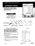
INSTALLATIONINSTRUCTIONS
GAS
AUTOMATICDRYER
PLEASE READ ALL INSTALLATIONINSTRUCTIONS AND REQUIREMENTS BEFORE INSTALLING
WARNING : For your safety the information in this
manual must be followed to minimize the risk of fire or
explosionor to preventproperty damage, personal injury or
loss of life.
_, ATTENTION : Pour votre securite, suivre les indications donnees dans ce manuel afin de reduire les risques
d'incendie ou d'explosion et d'eviter dommages materiels,
blessures et deces.
• Do not store or use gasolineor other flammablevapors
and liquids in the vicinity of this or any other appfiance,
Ne pas entreposer ni utiliser d'essence ou autres produits et vapeurs inflammables A proximit6 de cette
secheuseou de tout autre appareil 61ectrom6nager.
QUE FAIRE S'ILY A UNE ODEUR DE GAZ
WHATTO DO IFYOU SMELL GAS
• Do not try to light any appliance.
• N'allumer aucun appareil.
• Do not touch any electrical switch;do not use any
phone in your building,
• Ne toucher aucun commutateur6}etrique; ne pas utiliser le tel6phone dans votre maison ou votre immeuble.
• Clear the room, building or area of all occupants.
• Fairesortir tousles occupants de la piece, du Iogement
ou immeuble,ou de la vicinit&
• Immediately call your gas supplier from a neighbor's
phone. Follow the gas supplier's instructions.
• Appeler la compagnie de gas imm#diatement en utilisant le telephone d'un voisin. Suivre Lesinstructions de
la compagnie de gaz.
• If you cannot reach your gas supplier, call the fire
department.
Installation and service must be performed by a qualified
installer,service agency or the gas supplier.
• En cas d'impossibilit6 de joindre la compagnie de gaz,
appeler les pompiers.
Le montage et les reparationsdoivent _tre faits par un
technicien qualifie, un prestatairede services ou la compagnie de gaz.
FOR YOUR SAFETY AND THE PROPER OPERATION OF
YOUR NEW DRYER,THE DRYER MUST BE INSTALLED IN
ACCORDANCE WITH ALL THE INSTALLATIONREQUIREMENTS.
- TOOLS REQUIRED -
All literature should be removed from inside dryer and saved for
future reference.
W' DRIVER
PIPEWRENCH OR
ADJUSTABLEWRENCH
NOTE: DO NOT RAISE OR LOWER THE DRYER BY THE
BACKGUARD.
SCREWDRIVER
PUTTY KNIFE
PIPE SEAL COMPOUND
DUCT TAPE
BACKGUARD
1, To remove the corrugated crate base, place your foot on the
base close to a leveling foot. Pushing down firmly with your
REMOVE
foot, tiltBRIPPING
the dryer away
MATERIALS
from you.
/
2. Repeat process with all leveling feet (4). Remove excess
3. Remove film covering backguard for shipping purposes.
Wipe clean of fingerprints.
I
base by hand.
GAS CONNECTIONS
_i
II
_
Requirements.EQUIPPEDFOR NATURALGAS. FOR LP GAS
INSTALLATIONSEE PAGE2,
LEVELING
FOOT
The dryer must be installed in accordance with the Installation
P/N
____
CORRUGATED
BASE
53-3498
1
_
CRATE
PLACE FOOT
FOR LEVERAGE
PLEASE READ All Installation Instructions and Requirements Before Installing.
GENERAL INFORMATION
INSTALLATION IN RESIDENTIAL GARAGE
It is recommended that a qualified service technician install
your dryer,
Flammable Vapors - Vapors from spilled gasoline can be
ignited by a clothes dryer, a water heater, or other nonsealed gas heating appliance. The National Fuel Gas Code
ANSI Z223.1 and Canadian Code CAN 1-B149 requires that
a gas appliance when installed in a residential garage be
elevated so that the burner and the ignition device of the
burner are a minimum of 18 inches above the floor.To satisfy this requirementthe dryer must be installed with the base
at lease 14 in. above the floor.In addition, the dryer must be
located or protectedto prevent damage from movingvehicres.
Unless otherwise indicated on the nameplate (located inside
the door) this dryer is equipped for use with natural gas. If LP
gas is used, the proper conversion kit must be installed
by the dealer or distributor. The dryer installation should
be performed by a qualified person familiar with the precautions requiredand with local codes,
To obtain replacement parts contact any factory authorized
dealer.
FOR MAXIMUM SAFETY, INSTALLATION OF CLOTHES
DRYERS IN GARAGES SHOULD BE AVOIDED.
LOCATION
ELECTRICAL
This clothes dryer is designed so that it can be installed in
most locations in the home. The dryer may even be installed
in an unheated indoor location, such as a utility room or
building. However, with models having automatic dry cycles,
WHEN THE ROOM TEMPERATURE DROPS BELOW 50
DEG. F. OR 10 DEG. C. THE AUTOMATIC CYCLE MAY
NOT SHUT OFF. USE TIMED DRY CYCLE (HEAT NOT
FLUFF) IF AVAILABLE ON YOUR MODEL.
DO NOT INSTALLTHE DRYER ON A CARPETED FLOOR.
DO NOT INSTALL OR STORE THE DRYER WHERE IT
MAY BE EXPOSED TO THE WEATHER OR DRIPPING
WATER. If it is ever exposed to water, have a qualified technician check it before using. Clearances of 0 in. between
combustible construction and the front, sides, back and
exhaust duct are permissible.
THE INSTALLATION MUST BE MADE WITH ADEQUATE
CLEARANCE TO PERMIT SERVICING.
In ordinary installations enough air will be available for proper operation of the gas burner. However, if the dryer is
installed in a mobile home, a closet or a tightly sealed room,
provisions should be made for at least 18 square inches of
ventilation area. Air openings measuring a minimum 3 in. by
3 in. should be provided at the top and bottom of the closet
door. Ordinarily, Iouvered doors will satisfy the ventilation
requirements. Dryers installed in a bedroom, bathroom, or
closet must be exhausted outdoors.
FIRE HAZARD
CONNECTION
DO NOT USE AN EXTENSION CORD.
The dryer is designed for 120 volt, 60 HZ AC current and will
not operate on direct current or 50 HZ supplies.
It is recommended that a separate circuit be provided from
the main entrance panel to the dryer receptacle. The wiring
should be done by a qualified person in conformance with
local codes. The circuit must be protected with a 15 amp time
delay fuse or circuit breaker.
A wiring diagram is located behind backguard shield.
GROUNDING
The dryer, when installed, must be electrically grounded in
accordance with local codes, or in the absence of local
codes, with the latest revision of the National Electrical
Code. ANSI/NFPA No. 70 and the Canadian Electrical Code
C.22.1 Part 1.
This dryer is equipped with a three-prong plug on the power
supply cord, which must be plugged into a properly grounded three-prong wall receptacle for your protection against
possible shock hazard. Where the proper receptacle is not
installed, we strongly recommend that properly grounded
three-prong wall receptacle be instalred by a qualified electrician in accordance with the National Electrical Code,
Canadian Electrical Code, and local codes and ordinances.
GROUNDING PLUG
APPROVED GROUNDING
POWER SUPPLY CORD-
DO NOT ALLOW STORAGE OR ANY OTHER MATERIALS TO OBSTRUCT VENTILATIONOPENINGS.
NO OTHER FUEL-BURNINGAPPLIANCE SHOULD BE
INSTALLEDIN THE SAME ROOM OR CLOSET AS THE
DRYER.
TYPEWALL
RECEPTACLES.
THREE PRONG
_ _
GAS
CONNECTIONS
GAS
SUPPLY
PRESSURE
TESTING
Pressure testing of the Gas Supply Piping System:
THE
INSTALLATION
MUST
CONFORM
WITH
LOCAL
CODES or in the absence of local codes, with the latest
revision of the National Fuel Gas Code, ANSI Z223.1 or
CAN1-B149.
t. Test pressure in excess of _ psig (3.45 KPA).The dryer must be
disconnected from the gas supply piping system at the inlet gas
pipe connection.
2. Test pressures equal to or less than _ psig (3.45 KPA).The dryer
The gas inlet connection at the rear of the dryer is equipped
with a 3/8"- 18 N.S. pipe thread. The supply line must be '/£
black rigid pipe (pipe size should be increased for runs
longer than 20 feet). If local codes permit, it is recommended
that the dryer be connected to the gas supply with approved
semi-rigid metal tubing and listed connectors not over 6 feet
long.
_i_ CAUTION: Moderate pressure is all that is required
to make a tight joint. Do not use excessive force as
damage to the valve may occur,
must be isolated from the gas supply piping system by closing
the manual shut-off valve.
GAS VALVE INLET PRESSURE
TESTING
Manifold pressure is preset to 3'/, inch W.C. and does not
require adjustment. A 1/8NPT plugged pressure tap is avaiF
able in the gas valve body for test. To check the pressure proceed as follows:
a) Disconnect electric cord.
A '/8" NPT plugged tapping, accessible for test gauge connection, must be installed upstream of the gas supply connection to the dryer. This work must be done by a qualified
person,
b) Raise the top of the dryer as shown in FIG. #2, page 5.
c) Remove the front panel by removing two screws inside the top
corners of the front panel disconnecting the door switch wires
and hinging the front panel outward then lifting up.
d) Be sure the manual valve is off.
e) Remove the plug and install pressure tap.
Use an approved pipe seal compound that is resistant to L.P.
gas on all pipe thread connections,
f) Route pressure hose downward past the front of the base
between front panel hinges.
The National Fuel Gas Code, ANSI Z223.1 or CAN1-B149,
requires that an acceptable, approved manual gas shut
off valve be installed within 6 feet of the dryer,
g) Re-install front panel over pressure tap hose.
h) Connect the gauge, turn manual valve on the supply pipe, check
with dryer in operation.
To gain access to main gas valve, remove front panel (see Step
SHUTDOWN INSTRUCTIONS
#1 thru 3) under Bottom Exhausting, Page 5.)
To shutdown the dryer either turn timer to off position or open
the door then turn timer to off position. Turn Manual Gas Shut Off
Valve to OFE Unplug Dryer,
BEFORE OPERATING YOUR DRYER READ ALL SAFETY
CHECK ALL CONNECTIONS FOR LEAKS WITH SOAP AND
WATER.
DO NOT PURGE GAS LINE
AUTOMATIC
LISTED
IN THE
OPERATING
INSTRUC-
IGNITION
This dryer is equipped with an automatic ignition system which
does not require a manual lighting procedure. Start the dryer
and the system should purge itself and ignite.
When starting the dryer you may hear the gas ignite. This sound
is normal and should be no cause for alarm.
TURN OFF GAS AND UNPLUG BEFORE CONTINUING
INSTALLATION.
BURNER
PRECAUTIONS
TIONS.
ADJUSTMENT
IMPORTANT SAFETY NOTICE AND WARNING
The California Safe Drinking Water and Toxic Enforcement
Act of 1986 (Proposition 65) requires the Governor of
California to publish a list of substances known to the
State of California to cause cancer or reproductive harm,
and requires business to warn customers of potential
exposures to such substances.
No gas adjustment is necessary at normal altitudes since the
gas flow is controlled by a fixed-sized orifice for the main burner. For altitudes above 2,000 feet, the input must be reduced by
4% for each 1,000 feet above sea level, in some locations the
gas utility has reduced the B.T.U. content of the gas to provide
this compensation. In other locations, the burner orifice must be
changed. Consult your dealer or local gas utility for further informarion,
Users of this appliance are hereby warned that the burning of gas can result in low-level exposure to some of the
listed substances, including benzene, formaldehyde and
soot, due primarily to the incomplete combustion of natural gas or liquid petroleum (LP) fuels. Exhaust ducts should
be kept free of obstructions and properly exhausted dryers will minimize exposure.
1. LEVELING
2. STABILITY
3. SERVICE CONNECTION
COVER
PLATE-WITH HANDS
TO CHECKIF
LEVEL AND
STABLE
ROCK DRYER
FOOT
>_
Set all leveling feet at same height. A
minimum of '/_"clearance between the
machine and the floor is recommended. Adjust to match the height of your
washer,
w
_'
Place dryer in the location where it will
be used. Check, by rocking dryer with
hands on opposite corners, that all
four (4) feet are in firm contact with the
floor. If it rocks, adjust as needed,
DRYERVENTPIPE
/
GASINLET
_
There are three (3) service connections to your dryer, all located on the
back.
4. GAS CONNECTION
5. EXHAUST VENTING
6. OUTSIDE WALL
(DONOTPURGEGASLINE)
PLUGGEDTAPPING
/I \ 1/8-INCHNPT
GAS
\/
SRUT-OF
VALVE
_H
GAS INLET
PIPECONNECTION
GAS SUPPLY
LINE
l
_
OUTSIDEWALL
/
OUTSIDEEXHAUST/
VENT
_lb Check all connections for leaks.
Coat the threads with pipe seal compound, then connect the gas supply
line to the gas inlet on the dryer.
ALL GAS DRYERS MUST BE
VENTED TO THE OUTDOORS.
6A. BASEMENT WALL
6B. FLOOR EXHAUSTING
Attach dryer vent pipe to outside
exhaust vent. Outside exhaust vent
90°BASEMENTWINDOW_.
ELBOW4" DIA.
l lll H I/
WALL
S !E
t
BASEMENT
-_
-
_ _ ..o
In basements, the exhaust can be elevated by installing elbows to raise the
vent hood above the ground level,
-I
90° ELBOW
/
If space permits, a 4" dia. elbow pointed downward through the floor may be
used. If notthrough
possible,
dryer as
may
be
exhausted
thethe
bottom
illustrated later in this manual.
should fit over dryer vent pipe to avoid
catching
duct tape.lint. Tape all joints with heat
EXHAUST VENTING RECUIREVENTS
ALL GAS DRYERS
MUST BE VENTED
FIRE HAZARD
OUTDOORS
Numberof
NEVER CONNECT EXHAUST INTO ANY GAS VENT,
DUCT, CHIMNEY, WALL, CEILING, A'R'IC, CONFINED OR CONCEALED SPACE, BEDROOM, BATHROOM, CLOSET, OR UNDER A BUILDING.
90°Turns
Separated
by
at least4ff.
of StraightRun
--_
-.-P[ 4" I_
OPENING
45feet
0
NEVER USE PLASTIC OR OTHER COMBUSTIBLE
DUCTWORK.
VENTHOODTYPE
k
IX,
--
1
2
35 feet
25 feet
k
I%
""_12_"1 "_-
OPENING
30 feet
20 feet
10 feet
MULTIPLE INSTALLATIONS REQUIRE INDIVIDUAL
EXHAUST SYSTEMS.
BOTTOM
DRYERS
If space permits behind the dryer,a 4"elbow pointed down-
INSTALLED
IN
A
MANUFACTURED
(MOBILE) HOME MUST BE VENTED OUTDOORS.
EXHAUSTING
ward
beisused
pass thethe
exhaust
the
floor. may
If this
not to
possible,
dryer system
may bethrough
exhausted
through the bottom as illustratedin FIG. #4. When exhausting in this manner, the installation should be made accordingto the followingsteps:
PERIODICALLY CLEAN LINT FROM VENT SYSTEM.
CLEAN FREQUENTLY IF USING MAXIMUM LENGTH
OF VENT.
1. Disconnect electric cord.
Exhaustingcan be accomplisheddirectlyfrom the rear of the
cabinet, through right side of the cabinet, or downward
through the cabinet base. If yourexistingductworkis plastic,
2. Raise the top of the dryer by pressing in with a putty knife
on the top panel retainingclips.See FIG. #2.
four
inch diameter
galvanized
or aluminum
pipe should
be
nonmetal,
or combustible,
replace
it with METAL.
Standard
used. DO NOT use any pipe which may be susceptible to
rust or COMBUSTION. To avoid catching lint the crippled end
of each pipe section should face away from the dryer. Do not
use screws or other fasteners that extend into the exhaust
pipe or duct.
__
The use of a vent hood
on the outside is required.
_--Js
PPROX.4"
3. Remove front panel by removing two 1/4"screws inside top
corners of front panel. Disconnect door switch wires.
NOTE position of front seal before removing front panel.
4. Remove the cylinder as follows:
__
\/'_
_-
\
Flexible 4" diameter metal tubing may be used for exhausting
the dryer. However, the convolutions create a greater restriction than pipe and serious blockage can result if the tubing is
bent too sharply. If clearance to the wall is less than 8 inches, use a 4" sheet metal elbow at the rear of the dryer to
avoid a sharp bend in the tubing. Do not use over 8 feet of
flexible metallic tubing between the elbow and the vent hood.
VENTHOOD
\A/'/_/q'__
I f_
4J_/'_
..L3J,' _
FIG. #2
FIG. #3
OFBELTDOWN
_
- -
_=_
\_./_
When the dryer stops the damper automaticallycloses to
prevent drafts and the entrance of insects and rodents. To
avoid restrictingthe outlet, maintaina minimum 8 inchclearance between the hood and the ground or other obstruction.
GROOVED
SIDE
.,_S
DRYERFRONT
OF "''"J_\_
_llIJ//'_b_"_
J
_ _
_"q_
GROOVED
SIDE /
_'
OFBELTUP
FIG.#1
IDLERPULLEY
PULLEY
MOTOR
a. Force idler pulley to the right and remove cylinder belt
....
j
PIPECONNECTION ,._
I
from idler and motor pulleys. See FIG. #3.
5. Remove tape and screw securing dryer vent pipe.
EXHAUSTFLOW=
I
c.
FIG.
Lift
out
of cabinet.
b.
Lift#4.
up and
turn cylinder to clear the roller supports.
I
6. Remove the 4" dryer vent pipe and shorten to a suitable
INCORRECT
CORRECT
I
length. Length depends on type of elbow purchased.
LENGTHOFVENT
7. Remove knockout from dryer base.
MaximumLengthof4" RigidDuct
8. Place dryer in position and mark duct location on floor.
Check floorjoist locationbefore sawing hole in floor.
'
'
EXHAUSTFLOW_
_
9.
Saw a 4_A
" hole in floor and position dryer.
A 4" 90 degree elbow and length of 4" metal exhaust pipe
must be purchased. Shorten the rear exhaust pipe inside the
dryer as required. (Length will depend on type of elbow purchased.) Secure the shortened pipe to the Blower Housing
with a screw at the top, attach elbow and metal exhaust pipe,
and seal all joints with tape or silicone bathtub caulk.
10. Secure the shortened pipe to the blower housing with a
screw at the top and seal all joints with tape or silicone
bathtub caulk,
11. Install a 4" 90 degree elbow as shown in FIG. #4.
FIG.#4
--_
_____n_
When exhausting from the side, the installation should be
made according to the steps described in BOTTOM
EXHAUSTING and as noted above.
REPLACE
SCREW
ANDTAP_,7 90 DEGREEELBOW
/
_H
]_11
_
/J
4"DIA7
ilEVI
//[_',_
I1_ VENT PIPE l
(MOBILE) HOME INSTALLATIONS
SPECIAL
REQUIREMENTS
FOR MANUFACTURED
1. THE DRYER
INSTALLATION
must conform to the
Followinstalled
steps outlined
for installation
with these
exceptions:
When
in
a
manufactured
(mobile)
home:
Manufactured Home Construction
and Safety
Standard,
Title 24 CER, Part 32-80 (formerly the Federal Standard
for Mobile Home Construction and safety, Title 24, HUD
(Part 280, 1975).
Nr'_ II
12. Seal rear opening of cabinet with the cover plate provided with your dryer. Located with literature. Attach cover
plate to rear of the cabinet with #8 sheet metal screws
or duct tape. (not supplied)
13. Place cylinder belt around cylinder with grooved side
toward cylinder. FIG. #3.
2. A GAS SHUT OFF VALVE with a non-displaceable rotor
must be installed in the gas supply piping, This valve
must be located within the living space of the manufactured (mobile) home and within 3 feet of the dryer.
14. Reinstall cylinder by pushing and turning until rollers are
snapped in cylinder grooves and cylinder turns freely,
3. THE DRYER must have an exhaust duct which extends
to the outside atmosphere with the termination securely
15. Position cylinder belt with grooved side around motor
pulley. Pull idler pulley right until smooth side of belt can
be routed around left side of idler pulley. FIG. #3.
fastened to the mobile home structure and which is fabricated of a material that will not support combustion.
Standard four inch diameter galvanized or aluminum
pipe should be used. The dryer must be attached to the
manufactured (mobile) home structure as follows:
16. Rotate cylinder counter-clockwise to position belt.,
17. Replace dryer front and reconnect door switch wires,
Make sure the front seal is in the original position,
a. Dismantle the dryer as described in bottom exhausting.
18. Complete exhaust system to outdoors,
b. Buy two #10 x 1'/5" round head wood screws. Drive
them through the attachment screw holes of the base
into the floor. See FIG. #5 for location.
RIGHT SIDE EXHAUSTING
c. Reassemble the dryer.
Figure #5 illustrates a typical right side exhaust venting pipe
connections inside the dryer cabinet. When exhausting the
dryer from the side, the cabinet knockout must be removed,
FIG. #5
4. THE EXHAUST DUCT must be exhausted to the outside
using metal ducting. It should not terminate beneath the
manufactured (mobile) home.
5. THE VENT HOOD must be securely fastened to the
manufactured (mobile) home structure.
REAREXHAUSTING
THIS DRYER IS NOT SUITABLE FOR USE IN RECREEg_]L
,_
.......
I
ATTACHMENT
SCREW
HIGHT
SIDE
EXHAUSTING
CAMPERS, OR MOTOR HOMES.
AS TRAVEL
TRAILERS,
FINALSUCH
CHECK
OUT
r_
ATION VEHICLES
HOLE"
,
_"
i
manual shut-oft valves. Double check for gas leaks.
_Jg
/BLOWER|
HOUSING
L.,,,/FRO
r
ES.S
N_CC /
/
2. Plug dryer in. NEVER USE AN EXTENSION CORD.
1, After your gas dryer has been installed, turn on all
3, Following your operating instructions, operate the
dryer briefly on all control settings. A slight odor
may be noticed with a new machine.
4, Allow empty dryer to operate on highest heat
setting for a few minutes.
5. Stop dryer and wipe inside of cylinder with a clean
cloth,
6. Wipe fingerprintsand dirt from outside of dryer with
soft cloth,
6