1
BCP-3
Hydronic Multi-Stage Boiler Control
INSTALLATION AND OPERATION INSTRUCTIONS
Hot Water Control with
Outdoor Reset, Set
Point, and DHW for
Hydronic Applications
Two sensors are used, one to monitor the outdoor temperature
and one to monitor the circulating hot water temperature in
the heating system. When the outdoor temperature falls below
the outdoor cutoff setting, the heating system is activated
and the target water temperature is increased proportionally
to satisfy the load. Should it get warmer outdoors, the target
water temperature is automatically lowered by the control. If
the outdoor temperature continues to rise to the outdoor cutoff
setting then the heating system is turned off.
Black (120VAC power)
2 Line Alphanumeric Display
Displays sensor values and
menu settings
Output Lights indicate
output status
BCP-3
SYSTEM =
TARGET =
147F
150F
SYS
Boiler
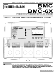
The BCP-3 is a multi-boiler or multi-stage outdoor reset
hydronic heating control. It establishes ambient comfort by
varying the temperature of the heating system’s circulating
hot water in response to changes in the outdoor temperature.
In addition, it provides an outdoor temperature based cutoff,
heating system pump control, and domestic hot water (DHW)
pump control. Two unique features have been added to this
control including a customized reset ratio curve. A Set Point
option was added for applications where outdoor reset will not
apply.
Because of the many different physical characteristics of
buildings including the type of radiation; i.e., baseboard or
radiant, the heat loss varies. In one building, a 1-degree
outdoors temperature change may require a change of 1 degree
in heating water temperature; for another it may require a
change of 2, 3, or even 4 degrees in order to gain the desired
comfort level. This is known as the Reset Ratio. The Reset
Ratio chart shows the wide range of Reset Ratios available for
the BCP-3 in addition to the customized reset ratio. See page 2.
DHW
Pump
Pump
Output 1 Output
2 Output
3
SET
Yellow (Output 1)
Display Section Locking Screws
WARNING
The installer fits the BCP-3 to a specific building by adjusting
the Reset Ratio curve. With curve number 4 (2:1 reset ratio)
a 2-degree change in outdoor temperature will change the
Blue (Output 2) circulating hot water temperature by 1 degree; at curve number
11(1:3 reset ratio) an outdoor change of 1 degree will change
the water temperature by 3 degrees. Most buildings with
White (Output 3) baseboard radiation require a curve of 6, 7, or 8. Radiant heat
applications usually require a lower curve. An external T-Stat
input can be used to shut the heating system down when the
This Weil McLain control is strictly an operating control; it should never be used as a
primary limit or safety control. All equipment must have its own certified limit and safety
controls required by local codes. The installer must verify proper operation and correct any
safety problems prior to the installation of this Weil McLain control.
Part Number 550-110-070/0308
BCP-3 Installation and Operation Manual
thermostat is satisfied. Another, is a Setback input that will switch the heating system to a
lower set point determined by the Set Back setting.
1:4 1:3
Radiators (Steel & Cast Iron)
Reset Ratio
Offset
220
1.00 (O) : 1.00 (S)
0˚F
210
200
Baseboard (Finned copper tube& Cast Iron)
1.00 (O) : 1.00 (S)
0˚F
Radiant (High Mass/Concrete)
4.00 (O) : 1.00 (S)
-10˚F
Radiant (Low Mass/Joists)
2.00 (O) : 1.00 (S)
-10˚F
Fan Coils & Air Handlers
1.00 (O) : 1.00 (S)
20˚F
An optional domestic hot water input is provided for systems where an indirect tank
provides DHW. During a DHW call, the BCP-3 will maintain a constant set point of
200°F or the Maximum Water Temperature setting, whichever is lower, regardless of
outdoor temperature or the status of the heating system. If 1-On/Off+2-Pumps Output
Mode option was selected, the DHW pump will be enabled whenever there is a call for
DHW. In addition, the heating system pump can be programmed to turn off during a
DHW call for up to 120 minutes to satisfy the DHW demand quicker while withholding
building heat.
Water Temperature (in °F)
Type of Radiation in Building
1:2
12 11
1:1.5
10
9
8 1:1.25
7 1:1
190
180
170
6 1.25:1
160
5 1.5:1
150
4 2:1
140
3 3:1
2 4:1
130
120
1 8:1
110
100
70
60
50
40
30
20
10
0
-10 -20
Outdoor Temperature (in °F)
Reset Ratio Curves
Reset Ratios are presented as
Outdoor : Water
Operation Concept
The BCP-3 has multiple Output Modes of operation. It can control any three output boiler-and-pump variety ranging from a single
On/Off boiler with a system pump to three individual boilers. In addition, it can accepts a DHW call signal to raise the target set point.
Moreover, if "1-On/Off+2-Pump" is selected as an Output Mode, it will control the DHW pump allowing it to energize on a DHW
call. (See Output Mode Table under the Startup Menu on page 4.)
Boiler Operation
• When a single On/Off boiler is selected as the primary function of the BCP-3, the boiler relay will energize when the System
Sensor reading is below the Target temperature less the Differential. Moreover, the Outdoor Sensor reading must be below the
Outdoor Cutoff setting and the EXT+/EXT- (Enable/Disable) terminals must be shorted using a dry-contact switch or a jumper. If
the System temperature exceeds the Target, the boiler relay will de-energize.
• If sequencing multiple stages or boilers are the primary function of the BCP-3, the BCP-3 will use the Purge Delay to start the lead
boiler. Then, it will use the Reaction Time to add additional stages or boilers. When subtracting stages, the BCP-3 will use only the
Minimum Run Time.
System Pump Operation
• When the BCP-3 is in one of the Output Modes that control the System Pump relay while the EXT+/EXT- (Enable/Disable)
terminals are shorted using a dry-contact switch or a jumper, the System Pump relay will energize, as long as the Outdoor Sensor
reading is below the Outdoor Cutoff setting. However, upon the opening of the EXT+/EXT- (Enable/Disable) terminals or if the
Outdoor Sensor reading rises two degrees above the Outdoor Cutoff setting, all boiler relays will de-energize and the System Pump
relay will remain energized for the Run-On delay period before de-energizing.
• If DHW Priority was set to other than "NO", a DHW call using terminals T3+/T3- (DHW call Input) will de-energize the System
Pump relay for the period of the DHW priority or the termination of the DHW call, whichever comes first. This will ensure all
boiler outputs are directed to produce domestic hot water.
• If DHW Priority was set to "NO", then a DHW call will not have any effect on the System Pump relay.
DHW Pump Operation
• When the BCP-3 is controlling the DHW Pump relay by selecting "1-On/Off+2-Pump" mode from the Output Modes, a DHW
call using terminals T3+/T3- (DHW call Input) will energize the DHW Pump relay. In addition, the BCP-3 will raise the Target
temperature to the lower of 200˚F or the Maximum Water temperature Setting.
• When the BCP-3 is in Outdoor Cutoff or when the EXT+/EXT- (Enable/Disable) terminals are open, a DHW call will energize only
the DHW Pump relay in a DHW Priority setting. See Output Mode Table on page 4. However, if No DHW Priority was selected,
both the System and DHW Pumps will energize on a DHW call.
2
BCP-3 Installation and Operation Manual
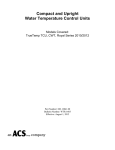
Base Section
Mounting the Controller
Display Section
Base Mounting Holes
• The BCP-3 is designed to mount on a 1900 (4”x4”) deep
electrical box.
• If additional room is needed for wiring use the extension
skirt provided.
• Place the BCP-3 in an indoor convenient location near
the unit to be controlled and away from excessive heat
or cold.
• Partially unscrew the Display Cover Mounting screws.
This allows for its removal.
• Lifting the Display Section away from the base starting
with the bottom will unplug it from the Base section.
• Proceed with the power and output wiring instructions.
• Use the screws provided to mount the BCP-3 to the
1900 box or the extension skirt.
• Mount Display Section back to the Base Section.
Tighten the Display Cover Mounting Screws.
T1 COM T2 COM T3+ T3- EXT+ EXT- P+ P- COM 24VAC
Input Terminals 24VAC optional power input
Display Cover Mounting Screws
120VAC Power Wiring
WARNING
Wiring
The BCP-3 can accept only one source of power:
120VAC or 24VAC. If more than one power source is
applied, the unit may be damaged.
BLACK
120VAC Power Source
BLACK
Wiring Power Input
The BCP-3 is designed to accept ONLY A SINGLE POWER SOURCE. It can be wired to
either 120VAC using the two Black wires or 24VAC using the right most two terminals on the
terminal block on bottom of the control. Weil McLain recommends the installation of a Surge
Suppressor and a Power Switch before the Power Line connection for safety and ease of service.
Input Terminals
System Sensors
24VAC
• Use a dedicated transformer with at least a 5VA output.
• Bring 24VAC to the two right most terminals on the front of the BCP-3 marked 24VAC and
COM.
{
Outdoor Sensor {
DHW Input Dry-Contact {
Enable/Disbale Input
Dry-Contact {
Setback Input Dry-Contact
{
24VAC power Input {
T1 COM T2 COM T3+ T3- EXT+ EXT- P+ P- COM 24VAC
120VAC
• Attach line voltage, 120VAC, to the two Black wires extending from the back of the BCP-3.
Remember to use the power line from a different source than the equipment being controlled.
24VAC Power Wiring
Wiring Input Terminals
24VAC Power Source
Sensor Wiring
System Temp
Strap-On Heating System Sensor (HSS) Installation
• Strap the sensor to the pipe using a metal clamps. Do not over tighten the clamp.
• Strap pipe insulation around the sensor and the pipe.
Outdoor Sensor
Immersion Heating System Sensor (HSS) Installation
• Install a 3/8"ID x 1/2"NPT immersion well.
• Insert the supplied sensor probe into the well.
Shield
T1 COM T2 COM T3+ T
Shield
Locating HSS
• Place the Heating System sensor in the common header where it will register the output of the
boilers before any takeoffs.
• Only use the Standard Brass Tube sensor provided.
• The sensor wires can be extended up to 500' using a shielded 2-conductor cable (Belden #8760 or
equivalent (#18/2)).
• Cut the shield and do not connect it at the sensor end. Only connect it at the control end using the outdoor
terminal marked COM. Do not ground the shield at the sensor but at the control using the COM terminal.
• Do not run sensor wires in conduit with line voltage wiring.
24VAC
EXT+ EXT- P+ P- COM 24VAC
Comm
Heating System Sensor (HSS) Installation (T1, COM)
3
BCP-3 Installation and Operation Manual
IMPORTANT
Determining the proper location for the Outdoor Sensor is very important.
The BCP-3 will base the heat on the outdoor temperature information it
receives from this location. If the sensor is in the sun, or covered with
ice, its reading will be different from the actual outdoor temperature.
Sensor Clip
Outdoor Sensor
Outdoor Sensor Installation (T2, COM)
•
•
•
•
•
•
•
•
•
The Outdoor Sensor must be used when Outdoor Reset is selected as the Control Mode
from the Startup menu. However, in Set Point mode, the Outdoor Sensor is optional.
When connected in that mode, it will be used as an input for the Outdoor Cutoff only.
Only use the Weil McLain sensor included with the unit.
Place the sensor in the shade on the north side of the building.
Be sure the location is away from doors, windows, exhaust fans, vents, or other heat
sources.
The sensor should be mounted approximately 10' feet above ground level.
Mount the sensor clip base to the outside of the building. Insert the sensor in the middle
and snap close the second clip on the sensor.
The sensor wires can be extended up to 500' using shielded 2-conductor cable.
Cut the shield and do not connect it at the sensor end. Only connect it at the control end
using the outdoor terminal marked COM.
Do not run sensor wires in conduit with line voltage wiring.
10' Minimum
Low Voltage
Sensor Wires
Wiring the Domestic Hot Water Call DHW (T3+, T3-)
•
•
•
•
A DHW call will raise system Set Point to 200°F or Maximum Target temperature,
whichever is lower.
When "1-On/Off+2-Pump" is selected as the Output Mode from the Startup menu, the BCP-3 can control the
operation of the Domestic Hot Water (DHW) pump using Output 3. See Output Mode Table on page 4.
DHW Call terminals are dry contact N.O. terminals.
Wire an aquastat or another control to provide dry contact closure on the DHW Call terminals.
DHW Call
Wiring
T1 COM T2 COM T3+ T3- EXT+ EXT-
Wiring the Enable/Disable (TSTAT) (EXT+, EXT-)
• The EXT terminals can be used to enable or disable the heat to the system by connecting it to a thermostat,
external control, or a switch. It accepts dry contact input only.
• If no thermostat or control is connected to the EXT terminals, leave the jumper supplied connected.
• No outputs will be active unless the EXT terminals are closed/shorted.
Enable/Disable
Wiring
Wiring the Setback/Boost (P+, P-)
•
•
The Setback feature can be used to provide the BCP-3 with a lower temperature Set Point when less heat is
required during night or unoccupied periods.
The Setback is activated by closing/shorting the P+ and P- terminals using an external control, i.e. timer or
switch.
COM T3+ T3- EXT+ EXT- P+ P- COM
Wiring Outputs
Setback/Boost
Wiring
Wire Colors and Output Lights
•
•
•
•
•
•
•
The BCP-3 has a three S.P.S.T. (N.O.) output relays. Each relay is rated at 1A Inductive load (1/8 HP).
The BCP-3 has three LED lights that follow the output relays' operation. When a relay energizes, its LED
will turn on. When the relay de-energizes, its LED will turn off.
The outputs are dry contacts only. They do not source any power.
The two Yellow wires represent Output 1 relay and the left LED.
The two Blue wires represent Output 2 relay and the middle LED.
The two White wires represent Output 3 relay and the right LED.
Depending on the Output Mode of operation selected during the Startup, the function of each
output will vary. See Output Mode Table for output wire colors and functions on page 4.
Boiler
3+ T3- EXT+ EXT- P+ P- COM 24VAC
SYS
DHW
Pump
Pump
Output 1 Output
2 Output
3
4
BCP-3 Installation and Operation Manual
Output Mode Table
Output Mode
Description
Output 1
(Yellow
Wires)
Output 2
(Blue
Wires)
Output 3
(White
Wires)
1-On/Off+1-Pump
One On/Off boiler and a System pump
Sys Pump
Boiler
Not used
1-On/Off+2-Pump
One On/Off boiler, a System pump and
a Domestic Hot Water Pump
Sys Pump
Boiler
DHW
Pump
2-On/Off+1-Pump Two On/Off boilers and a System pump Sys Pump
Boiler 1
Boiler 2
DHW Pump
controlled by DHW
Aquastat
1-Lo/Hi+1-Pump
One Lo/Hi boiler and a System pump
Sys Pump
Boiler Lo
Boiler Hi
DHW Pump
controlled by DHW
Aquastat
3-On/Off
Three On/Off boilers and NO pumps
Boiler 1
Boiler 2
Boiler 3
Sys Pump controlled
using other controls
or run constantly.
Wiring the Boiler Output
Single-Stage (On/Off) Boiler Wiring
• If any of the "1-On/Off" Output Modes is selected, wire the two Blue wires to the boiler circuit.
• If more than one On/Off boiler is to be controlled by the BCP-3, follow the wiring colors as per
the Output Mode Table above.
• The BCP-3 does not source any output power to the boiler. The relay makes when energized.
Two-Stage (Lo/Hi) Boiler wiring
• Wire the two Blue wires to the boiler control circuit initiating the Low Fire signal.
• Then, wire the two White wires to the High fire circuit.
• The BCP-3 does not source any output power to the boiler. The relay makes when energized.
Wiring the System and DHW Pump Outputs
System Pump Wiring (Not Available With "3-On/Off" Output Mode)
• The BCP-3 will control the System Pump relay (Maximum of 1/8 HP) in all Output Modes
except (3-On/Off), as all outputs will be used by boiler stages. In this scenario, the system pump
can be controlled independently using a switch or left to run constantly.
• Wire the two Yellow wires to the System Pump circuit.
• The BCP-3 does not source any output power to the pump. The relay makes when energized to
switch the power to the pump on.
DHW Pump Wiring (Available Only With "1-On/Off+2-Pumps" Output Mode)
• The BCP-3 will control the DHW Pump relay (Maximum of 1/8 HP) only in (1-On/Off+2-Pump)
Output Mode. In the other modes, the DHW pump can be controlled using an external DHW
aquastat.
• If the BCP-3 is controlling the DHW pump, wire the two White wires to the DHW Pump circuit.
• The BCP-3 does not source any output power to the pump. The relay makes when energized to
switch the power to the pump on.
Notes
On/Off Boiler
Output Wiring
Blue
Two-Stage Boiler
Output Wiring
Blue (Lo Fire)
White (Hi Fire)
System Pump
Output Wiring
YELLOW
L N
120VAC
DHW Pump
Output Wiring
WHITE
L N
120VAC
5
BCP-3 Installation and Operation Manual
BCP-3 Output Modes Wiring
147F
150F
SYS
L 120 VAC
N
Power (Black)
DHW
147F
150F
SYS
Boiler 1 Output
Pump 3
Pump 2 Output
Output
L 120 VAC
N
BCP-3
SYSTEM =
TARGET =
Power (Black)
DHW
DHW Pump (White/Output 3)
BCP-3
SYSTEM =
TARGET =
Boiler 1 Output
Pump 3
Pump 2 Output
Output
SET
SET
T1
COM
T2
COM
T3+
T3EXT+
EXTP+
PCOM
24VAC
T1
COM
T2
COM
T3+
T3EXT+
EXTP+
PCOM
24VAC
Output capped
(White/Output 3)
BCP-3
SYSTEM =
TARGET =
147F
150F
SYS
Wiring 1 On/Off Boiler +
System Pump
Power (Black)
L
N 120 VAC
DHW Call
Enable Dry Contact
Setback Timer
System Pump
(Yellow/Output 1)
BCP-3
SYSTEM =
TARGET =
DHW
SYS
Boiler
Pump
Pump
Output 1 Output
2 Output
3
147F
150F
Boiler2
(White/
Output 3)
T1
COM
T2
COM
T3+
T3EXT+
EXTP+
PCOM
24VAC
L 120 VAC
N
BCP-3
147F
150F
SYS
L 120 VAC
N
System Pump
(Yellow/Output 1)
Wiring 2 On/Off Boilers +
System Pump
Power (Black)
DHW Call
Enable Dry Contact
Setback Timer
Boiler Lo Boiler Hi
(Blue/ (White/
Output 2) Output 3)
System Sensor
Outdoor Sensor
DHW Call
Enable Dry Contact
Setback Timer
System Sensor
Outdoor Sensor
Power (Black)
SET
SYSTEM =
TARGET =
L 120 VAC
N
System Pump
(Yellow/Output 1)
Wiring 1 Lo/Hi Boiler +
System Pump
L
N 120 VAC
DHW
Pump
Pump
Output 1 Output
2 Output
3
NOTES:
SET
T1
COM
T2
COM
T3+
T3EXT+
EXTP+
PCOM
24VAC
Boiler 3
(White/
Output 3)
DHW Call
Enable Dry Contact
Setback Timer
Boiler 2
(Blue/
Output 2)
System Sensor
Outdoor Sensor
Wiring 1 On/Off Boiler +
System Pump + DHW Pump
DHW
Boiler1
(Blue/
Output 2)
6
System Pump
(Yellow/Output 1)
Pump
Pump
Output 1 Output
2 Output
3
SET
Boiler
L 120 VAC
N
T1
COM
T2
COM
T3+
T3EXT+
EXTP+
PCOM
24VAC
Boiler
L 120 VAC
N
Boiler
(Blue/
output 2)
System Sensor
Outdoor Sensor
DHW Call
Enable Dry Contact
Setback Timer
System Sensor
Outdoor Sensor
Boiler
(Blue/
Output 2B)
Boiler 1
(Yellow/
Output 1)
Wiring 3 On/Off Boilers
• The BCP-3 does not source any output power
to any of its relays. A power source must supply the pumps with power and the control can
break the hot leg.
• Weil McLain recommends not sharing the
power source to the control with any pumps,
boilers, or heavy electric equipment.
• When wiring a sensor to the BCP-3, connect
the Shield to the COM terminal on the BCP-3
end. DO NOT connect the Shield at the sensor
end.
• Eventhough in some Output Modes the BCP-3
does not control the DHW Pump, a DHW call
will raise the System Target to whichever is
lower of 200F or the Maximum Water Temp.
BCP-3 Installation and Operation Manual
Menus
Startup Menu
Weil McLain
V1.00 (c) 2008
BCP-3
Boiler Control
SENSOR
Output
Output
SETUP COMPLETE!
PRESS SET
FAULT:
On
Off
Default Screen
SYSTEM=
TARGET=
Loading Default
Values...
-OUTPUT MODE-1-On/Off+1-Pump
1-On/Off+2-Pump
2-On/Off+1-Pump
1-Lo/Hi+1-Pump
3-On/Off
CONTROL MODE:
Outdoor Reset
Set Point
Cutoff:
60 F
Set Point:
170 F
Set Point
Operating Menu
------MAIN-----Set Point 170 F
<Out. Reset>
<Settings>
<Maintenance>
<Sys. Startup>
<Info>
<Back>
Reset
Reset Ratio O/S:
Custom
1(8.00 / 1.00)
2(4.00 / 1.00)
3(3.00 / 1.00)
4(2.00 / 1.00)
5(1.50 / 1.00)
6(1.25 / 1.00)
7(1.00 / 1.00)
8(1.00 / 1.25)
9(1.00 / 1.50)
10(1.00 / 2.00)
11(1.00 / 3.00)
12(1.00 / 4.00)
-OUTDOOR RESET-Reset Ratio
7
Offset
+0 F
Cutoff
60 F
Min Tgt.
140 F
Max Tgt.
200 F
<Back>
Max Target:
200 F
Min Target:
140 F
On
STARTUP
---MAINTENANCE--Sys. Trim
+0 F
Out. Trim
+0 F
<Back>
Outdoor
+0 F
Trim:
Trim:
Setback:
20 F
----SETTINGS---Diff.
5 F
<Stage>
Run-On
2m
DHW Prior
60m
Setback
20 F
<Back>
DHW
60m
Pump
2m
Set SYS
100 F
At OD
70 F
Priority:
Temp
Temp
Set SYS
170 F
At OD
0 F
Run-On:
--STAGE SETTINGSReaction
2m
Purge
1.0m
Min. Runtime 2m
Lead
Output 1
Rotate
Time
<Back>
Offset:
+0 F
Multi-Stage
SYSTEM
No
Yes
Differential:
5 F
1-Stage
BCP-3 V1.00
Setpoint F
FAULT: Output
Boost:
No
Yes
UNIT:
68 F
150 F
SET
System
+0 F
DISPLAY
F
C
1:
1:
Temp
Temp
2:
2:
Lead Boiler:
Output 1
MultiBoiler
Lead Rotation:
Time
Manual
Rotation
24hrs
Period:
7
BCP-3 Installation and Operation Manual
Button and Navigating Menus
The BCP-3 has three buttons.
• The SET button function varies. When the Default Screen is
displayed, pressing the SET Button views the MENU. When
in the Menus and settings, the SET Button accepts the selected
entry or setting value.
• When in the menus, pressing the Up and Down buttons will
scroll through the menu options. They can be used to change
the setting of a specific function. I.e., change the Set Point,
Differential, or System Trim. In addition, when in the default
screen, the Up and Down buttons will display the outdoor
temperature and Outdoor Cutoff.
• At the end of every operation menu there is a <Back> option
that allows the user to go back one menu level. If the SET
Button was held down for three seconds on the <Back>
option, the display will go back to the default screen.
Startup Options
When the control is initiated for the first time or after a manual
reset, it will start its operation with the Startup Menu. Later, the
Startup menu can be accessed as an option from the operation
menu. An option must be accepted in each screen in the Startup
Menu to move to the next level.
SET
SE
T
DISPLAY
F
C
UNIT:
CONTROL MODE:
Outdoor Reset
Set Point
Display Unit
Options: ºF, ºC
Default: ºF
SET
/<System Startup>/Display Unit
• The BCP-3 will offer two different temperature display standards. If ºF is selected, all
temperatures will display in Fahrenheit. If ºC is selected, all temperatures will display in Celsius.
Control Mode
Options: Outdoor Reset, Set Point
Default: Outdoor Reset
SET
/<System Startup>/Display Unit/Control Mode
• The new BCP-3 has two heating logics. Outdoor Reset; varies the system set point/target
based on outdoor temperature. This selection adds several menu options to adjust and fine tune
the reset curves: Reset Ratio, Offset, Min Water temp, Max Water temp, and Outdoor Cutoff. In
addition, a customized reset ratio curve will be available for specialized applications.
• Set Point; gives the installer the flexibility of selecting a fixed set point. The Outdoor Cutoff will
be available if an outdoor sensor was installed.
Output Mode
Options: 1-On/Off+1-Pump, 1-On/Off+2-Pump, 2-On/Off+1-Pump, 3-On/Off
Default: 2-On/Off+1-Pump
SET
/<System Startup>/Display Unit/Control Mode/Output Mode
• The new BCP-3 has multiple operating Output Modes of heating. Each can be applied based on
the number of boilers, stages, and pumps controlled. See Output Mode Table on page 4.
Sensor Fault
Options: Output On, Output Off
Default: Output On
SET
/<System Startup>/..../Sensor Fault
• The Sensor Fault will determine the operating status of the output relays when a sensor reads
Short or Open. On sensor fault, the Set Point will indicate FAULT TGT=ON or OFF to
indicate the condition of the output and the faulty sensor will read OPEN or SHORT to indicate
the condition of the sensor.
8
OUTPUT MODE:
1-On/Off+1-Pump
1-On/Off+2-Pump
2-On/Off+1-Pump
1-Lo/Hi+1-Pump
3-On/Off
SENSOR
Output
Output
DISPLAY
F
C
FAULT:
On
Off
UNIT:
CONTROL MODE:
Outdoor Reset
Set Point
OUTPUT MODE:
1-On/Off+1-Pump
1-On/Off+2-Pump
2-On/Off+1-Pump
1-Lo/Hi+1-Pump
3-On/Off
SENSOR FAULT:
Output On
Output Off
BCP-3 Installation and Operation Manual
Outdoor Reset Mode
• When Output-On is selected, the BCP-3 will energize all boiler and system relays when the System reads SHORT or OPEN and
Outdoor is below Outdoor Cutoff. Thus, all boilers will run on their limits. However, if the Outdoor sensor fails and the Outdoor
reads SHORT or OPEN, the BCP-3 will change the Target Set Point to the Max Water Temperature.
• When Output-Off is selected, the BCP-3 will turn all boilers Off when the System sensor reads SHORT or OPEN. However,
when the Outdoor sensor reads SHORT or OPEN, the BCP-3 will change the Target Set Point to be the Min Water Temperature.
Set Point Mode
• When Output On is selected, the BCP-3 will turn all boilers On when the System sensor reads SHORT or OPEN.
• When Output-Off is selected, the BCP-3 will turn all boilers Off when the System sensor reads SHORT or OPEN.
• The Outdoor Sensor fault status will not affect the control operation in Set Point mode. And, no Outdoor Cutoff will be available.
Setting the Control to Factory Default
SET
To Reset the BCP-3 control to its original factory defaults, power down the control. Hold down the
SET and DOWN buttons while powering the control back up until the Loading Default Values screen
Loading Default
appears. The Display will direct you to the Startup menu after the defaults are loaded to program the
Values...
control.
NOTE: When resetting the control to original factory defaults all control settings will be over written and will no longer exist.
Default Display
The default display will show the current System temperature and the Target temperature. By clicking
the Up or Down button, the display will show the current Outdoor temperature and the Outdoor
Cutoff.
SYSTEM=
TARGET=
148 F
150 F
SET
SET
Outdoor=
Cutoff=
48 F
65 F
Operating Menu Options (Click SET Button)
Set Point (Available when Startup Control Mode = Set Point)
Options: From -30ºF/-34ºC to 250ºF/121ºC
Default: 140ºF/60ºC
SET
/Set Point
• The Set Point option provides the user with an adjustable fixed Target temperature to control the
system. If an Outdoor Sensor was connected, the next menu option will show Outdoor Cutoff.
Otherwise, there will be no Outdoor Cutoff option.
• The Set Point less the Differential should be set above the boiler manufacturer minimum water
temperature requirements to protect the boilers.
Outdoor Reset (Available when Startup Control Mode = Outdoor Reset)
Options: From 1(8.00º/1.00º) to 12(1.00º/4.00º), and Custom
Default: 7(1.00º/1.00º)
SET
/<Out. Reset>/Reset Ratio
• The Reset Ratio determines how the System Target temperature will vary with Outdoor
temperature changes. The colder it gets outside, the hotter the Target will be. The Ratio is
measured as; Outdoor (O): System Water (S).
• With a 1.00:4.00 ratio, the System water temperature will increase rapidly as the outside
temperature falls hitting the maximum default water temperature of 240°F at 35°F outdoor
temperature. With a 4.00 (O):1.00 (S) ratio, the System water temperature (S) will increase
slowly as the outside temperature (O) falls.
• The Reset Ratio controls the amount of heat entering the heating system based on the outdoor
temperature. A higher numbered Reset Ratio will result in a higher Calculated water temperature.
See the Reset Ratio chart on page 2. If the application has radiant heat, a lower numbered Reset
Ratio curve should be selected. See Type of Radiation in Building Table on page 2.
• Reset Ratios are adjustable based on the building and application. See suggested ratios on page 2.
Set Point:
140 F
160 F
SYSTEM=
TARGET=
68 F
160 F
Reset Ratio O/S:
Custom
1(8.00 / 1.00)
2(4.00 / 1.00)
3(3.00 / 1.00)
4(2.00 / 1.00)
5(1.50 / 1.00)
6(1.25 / 1.00)
7(1.00 / 1.00)
8(1.00 / 1.25)
9(1.00 / 1.50)
10(1.00 / 2.00)
11(1.00 / 3.00)
12(1.00 / 4.00)
9
BCP-3 Installation and Operation Manual
•
•
If required: Adjust the RESET RATIO in cold weather. If the ambient building temperatures are too cold in cold weather,
move the ratio to a higher selection. That is, if 1.00 (O):1.00 (S) was initially selected, change the selection to 1.00 (O):1.25 (S).
If the building temperatures are too warm in cold weather, move the ratio to a lower selection. That is, if 1.00 (O):1.00 (S) was
initially selected, change the selection to 1.25 (O):1.00 (S).
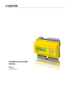
The Custom option gives the user the capability of creating a specialized Reset Ratio curve. Setting two points on the Reset Ratio
chart generates the customized curve. Each point requires a System Water Temperature SYS and an Outdoor Temperature OD.
The line connecting the two points will be the reset ratio. The Offset, Minimum Target and Maximum Target settings will still
apply to the customized curve.
Set SYS
100 F
Custom Outdoor Reset Curve
Offset (Available when Startup Control Mode = Outdoor Reset)
At OD
70 F
Temp
Point1: System=120°F
Oudoor=60°F
1:
170
160
s
Cu
150
1:
Point2: System=170°F
Oudoor=0°F
Max Target
180
Water Temperature (in °F)
Options: Sys Temp 1, 2 (-10ºF/21ºC) to (210ºF/99ºC)
Default: 1(100ºF/38ºC), 2(171ºF/77ºC)
Options: Outdoor Temp 1, 2 (-10ºF/-23ºC) to (100ºF/38ºC) Default: 1(70ºF/21ºC), 2(0ºF/-18ºC)
SET
/<Out. Reset>/Reset Ratio/Custom
• For situations where the standard reset ratios do not provide the perfect building heat-loss
equilibrium, the customized option can be used.
• The Custom Reset Ratio is only available when Custom is selected from the Reset Ratio menu.
It provides the user with the capability of assigning two points on the reset ratio diagram and use
the line that connects those two points as the customized reset ratio curve. Each of the two points
will need a specific System and Outdoor Temperature to identify it on the diagram.
• To Specify the first point, set Sys Temp 1, and OD Temp 1. Then, set Sys Temp 2, and OD
Temp 2, to set the second point on the curve. The two points can be any where on the line, not
necessarily at the ends.
• The chart shows an example of a customized curve 6(O):5(S) that does not exist in the standard
curve options. If the outdoor temperature reaches 30ºF, the system target will be 145ºF.
• Remember that the Min Target and Max Target apply to all reset ratios including the custom reset
ratio ones.
Temp
m
to
dR
ize
es
et
tio
Ra
Point2
140
130
Point1 Min Target
120
110
100
70
60
50
40
30
20
10
0
-10 -20
Outdoor Temperature (in °F)
Custom Reset Ratio
Offset:
Options: From -40ºF/-22ºC to +40ºF/+22ºC
Default: 0ºF/0ºC
+0 F
SET
/<Out. Reset>/Offset
• The Offset setting adjusts the starting points of the Reset Ratio curves. This means that, regardless of the Outdoor temperature
or the Reset Ratio, when the Offset setting is changed, that change is directly added to or subtracted from the calculated Target.
For example, if the Set Point temperature was 130°F and the Offset was changed from 0° to +10°, then the Set Point temperature
would increase to 140°F
• If required: Adjust the Water Offset in mild weather. If the ambient building temperatures are too warm in the mild weather,
decrease the Offset. If the ambient building temperatures are too cold in the mild weather, increase the Offset. The rule of thumb
for baseboard radiation is to change the Offset 4°F for every 1°F you wish to change the building temperatures. In radiant heat
applications, change the Offset 1°F or 2°F for every 1°F you wish to change the building temperature. See Type of Radiation in
Building Table on page 2.
Outdoor Cutoff
Cutoff:
Options: Off, 30ºF/0ºC to 75ºF/25ºC, On
Default: 60ºF/16ºC
60 F
/Set Point/Cutoff
in Set Point
SET
/Set Point/<Out. Reset>/Cutoff
in Reset
• In Set Point Mode, if the outdoor sensor is installed, the Outdoor Cutoff setting screen will
automatically appear after the temperature Set Point has been selected.
• The Outdoor and Cutoff temperatures can be viewed from the default screen by clicking the Up or Down buttons.
• When the outdoor temperature falls to the adjustable Outdoor Cutoff temperature, the BCP-3 will control the System Pump and
Boiler relays to provide heat.
• When the outdoor temperature rises to the Outdoor Cutoff plus a 2°F differential, the BCP-3 will turn the boilers off. The System
relay will remain energized for the Run-On delay then de-energize.
• The Outdoor Cutoff can be set from 30°F to 75°F. In addition, the Setting can be set to ON or OFF. If ON is selected, the System
Relay will run regardless of the Outdoor temperature and the boilers will be active to hold the calculated water temperature. If
OFF is selected, the System and Boiler relays will always be off.
10
BCP-3 Installation and Operation Manual
Minimum Target (Available when Startup Control Mode = Outdoor Reset)
Options: From 70ºF/21ºC to 170ºF/77ºC
Default: 140ºF/60ºC
Min Target:
SET
/Set Point/<Out. Reset>/Min. Tgt
140 F
• The Minimum Target Temperature must be set to the boiler manufacturer’s specification.
The BCP-3 will calculate the Target based on the Outdoor temperature, the Reset Ratio, and the Offset value. The BCP-3 will
control the boiler to hold the higher of either the calculated temperature or the Minimum Target Temperature.
• The Minimum Target Temperature must be at least 20°F lower than the Maximum Temperature (See next setting).
Maximum Target (Available when Startup Control Mode = Outdoor Reset)
Options: From 90ºF/38ºC to 240ºF/116ºC
Default: 200ºF/93ºC
Max Target:
SET
/Set Point/<Out. Reset>/Max. Tgt
200 F
• This is the highest Target Temperature the BCP-3 will circulate through the heating system.
• When using a radiation system, it should be set according to the tubing or floor manufacturer’s specification.
• The Maximum Temperature must be at least 20°F higher than the Minimum Temperature.
Reaction
5m
--STAGE SETTINGSReaction
2m
Purge
0.0m
Min. Runtime 2m
Lead
Output 1
Rotate
Time
<Back>
Stage Menu Options
/<Settings>/<Stage>
This menu is only available when multiple stages or multiple
boilers are selected as the Output Mode from the Startup Menu.
Rotation
24hrs
Period:
Reaction Time
Options: 1 to 10 minutes
Default: 2 minutes
SET
/<Settings>/<Stage>/Reaction
• It is the amount of time it takes a single stage to affect the system.
• After the BCP-3 turns on a stage trying to meet a set point, it will not turn on another stage until
the reaction time has elapsed. Then, it will recalculate if an additional stage is need.
• To determine the optimum time, in a heating system start with a hot system. Then, turn on a
single stage and calculate how long it takes until the system begins to respond to that stage by
rising an additional 2°F. That period should be set as the Reaction Time.
Purge
Options: 0.0 to 10 minutes
Default: 1.0 minutes
SET
/<Settings>/<Stage>/Purge
• Most large units must go through a purge cycle before they are brought on line.
• When the BCP-3 activates a unit (the lowest firing stage on a boiler), it does not start to calculate
its output until the Purge Delay is over. This allows the boiler to fully come on and begin
producing output.
• The Purge Delay helps prevent short cycling of newly activated boilers. Once the lowest boiler
stage is activated, it MUST run through the entire Purge Delay period before starting the Reaction
Time calculation..
• The Purge Delay setting MUST be set to the time required by the boiler's manufacturer
specification.
Purge
1.0m
Time:
Delay:
Minimum
2m
Runtime:
Lead Boiler:
Output 1
Lead Rotation:
Time
Manual
Reaction
2m
Time:
Purge Delay:
1.0m
11
BCP-3 Installation and Operation Manual
Minimum Runtime
Options: 1 to 60 minutes
Default: 2 minutes
SET
/<Settings>/<Stage>/Min. Runtime
• This is the minimum amount of time any stage will run.
• The Minimum Runtime for the lowest firing stage on a boiler starts after the purge cycle.
• Initially, set the Min. Runtime to half the Reaction Time.
• If System tends to overshoot, reduce the Min. Runtime. If boilers tend to short cycle, increase the
Min. Runtime.
Lead Boiler (Not Available for Lo/Hi or 1-On/Off Output Modes)
Options: Output 1, Output 2, or Output 3
Default: Output 1
SET
/<Settings>/<Stage>/Lead
• The Lead boiler will always be the first boiler brought on when there is a call for output. As more
heat is needed, additional boilers are added.
Lead Rotation (Not Available for Lo/Hi or 1-On/Off Output Modes)
Lead Rotation Options: Manual or Time
Default: Time
Rotation Period Options: 1 to 999 Hours
Default: 24 Hours
SET
/<Settings>/<Stage>/Lead
SET
/<Settings>/<Stage>/Lead/Rotate
• The Lead boiler can be rotated automatically based on time or manually. The Time rotation is
recommended for most applications.
• If Time is selected, a second screen will allow the adjustment of the Auto Rotate Period If
24 Hours (default setting) was selected, the first rotation will take effect after 12 hours. The
following rotations will take place every 24 hours thereafter.
• If Manual Lead Rotation is selected, it will be followed by the Lead Boiler selection option. (See
previous topic.)
Minimum
2m
Runtime:
Lead Boiler:
Output 1
Lead Rotation:
Time
Manual
Rotation
24hrs
Period:
Single On/Off Boiler and System Pump Settings
Differential (Available for Single-Boiler Applications only)
Differential:
Options: From 1ºF/1ºC to 20ºF/11ºC
Default: 5ºF/3ºC
5 F
SET
/<Settings>/Diff.
• The Differential controls boiler cycling. When there is a call for heat, the boiler will be activated until the Calculated temperature
is reached. The boiler will then turn off and stay off until the system water temperature falls to the Set Point less the Differential.
• A smaller Differential setting will normally result in tighter control of the set point but will tend to increase the frequency of
boiler cycling. Larger Differential values will reduce boiler short cycling, but the system will be allowed to vary further from the
target value.
Run-On (Not Available for 3-On/Off Output Mode)
Pump
Run-On:
Options: From 0 min to 60 min
Default: 2 min
2m
SET
/<Settings>/Run On
• The System Pump relay will energize whenever the Outdoor temperature is below the Outdoor Cutoff. When the Outdoor
temperature increases 2°F above the Outdoor Cutoff and after the boiler relay has de-energized, the pump relay will stay on for a
period set by the Run-On. This allows the Pump to dissipate the residual heat within the boilers back into the system.
• The Run-On time should be set based on the size and type of the boilers and pump. In general, a boiler with large water content
and high horsepower will need a longer Run-On than a boiler with the same horsepower and less water content. (Refer to boiler
manufacturer recommendation).
• When DHW Priority is selected while the EXT+/EXT- (Enable/Disable terminals) are open or the outdoor temperature is above
the Outdoor Cutoff, a DHW call will energize only the DHW relay. When the DHW call expires, the DHW Pump relay will run
for the Run-On period then de-energize.
12
BCP-3 Installation and Operation Manual
Domestic Hot Water (DHW) Priority
DHW
Priority:
Options: NO and From 1 min to 120 min
Default: NO
60m
SET
/Settings>/DHW Prior.
• The DHW Priority, with a value set to other than NO, provides the user with an adjustable DHW priority timer for the domestic
hot water call. That is, initiating a DHW call will de-energize the system pump relay for the period set by the DHW Priority.
However, the DHW relay, when 1-On/Off+2-Pump is selected as the Output mode from the Startup menu, will remain energized
for as long as the DHW is active. This will take place whenever the Outdoor temperature is below Outdoor Cutoff and the EXT+/
EXT- (Enable/Disable terminals) are closed/shorted.
• On the other hand, when the EXT+/EXT- (Enable/Disable terminals) are open or the Outdoor temperature is 2°F above the
Outdoor Cutoff, a DHW priority call will energize the DHW pump and boiler relays. When the DHW call expires, the DHW
Pump relay will remain energized for the Run-On delay then de-energize.
• If NO was selected as the option for the DHW Priority, a DHW call will energize both relays, system pump and DHW pump even
when TSTAT is de-activated.
Setback
Setback:
Options: From 0ºF/0ºC to 80ºF/44ºC
Default: 10ºF/6ºC
20 F
SET
/Settings>/Setback.
SYSTEM=
68 F
• The Setback feature can be used to provide the BCP-3 with a lower temperature Set Point when
SBC
TGT=
140
F
less heat is required by closing the P+ and P- terminals.
• The lower Set Point will appear on the main display indicating SBC TGT= .
• For example; when the calculated temperature is 160°F and the Setback is set to 20°F, a setback call will change the Set Point to
(160°F - 20°F) 140°F.
• A typical use for the Setback is to provide a reduced system temperature to a building during the night or on the weekends when
building is not occupied, but heat is still required.
• The Setback is activated by closing/shorting the P+ and P- terminals using an external timer, control, or a switch.
Boost
Options: Yes, No
Default: No
SET
/Settings>/Setback/Boost.
• The morning Boost is designed to return the building to comfortable ambient temperatures
after the night Setback period. The BCP-3 will accomplish this by running elevated water
temperatures (will add Setback setting to calculated water temperature) for 30 minutes after
the opening of the setback terminals P+ and P-. That is, if the normal set point at a specific
outdoor was 145˚F and the Setback setting was 20˚F, the boost will raise the system calculated
temperature to 165˚F for 30 minutes after the setback.
System and Outdoor Trim
Options: From -20Fº/-11Cº to +20Fº/+11Cº
Default: 0Fº/0Cº
SET
/<Maintenance>/Sys. Trm or Out. Trim
• The Weil McLain sensors are very accurate. However, sometime it might be beneficial to adjust
the values to match and existing system. The System and Outdoor Trim values adjust the System
Sensor and Outdoor Sensor readings using positive or negative values.
Enable/Disable (TSTAT) Input
•
•
•
•
The BCP-3 will provide heat only if the EXT- and EXT+ terminals are shorted. If no external
equipment or switch is connected to these terminals, leave the factory jumper installed.
When the terminals are OPEN, the Target will display TSTAT OPEN.
Even if the EXT terminals are open, a call for DHW will energize the output relays based on the
DHW Priority configuration.
The Enable /Disable terminals can be used as a Summer/Winter switch when connected to an
external switch.
NOTE: On a sensor fault while the Enable/Disable terminals are open, the control will follow the
Enable /Disable state regardless of the sensor fault condition.
Boost:
No
Yes
System
+0 F
Trim:
Outdoor
+0 F
Trim:
Enable/Disable
Wiring
COM T3+ T3- EXT+ EXT- P+ P- COM 24
SYSTEM=
TSTAT
55 F
OPEN
SYSTEM=
TSTAT
SHORT
OPEN
13
BCP-3 Installation and Operation Manual
Troubleshooting
No Display or LED Lights
Check the power to the BCP-3. The BCP-3 requires 120VAC power to the Black wires or 24VAC to the right-most terminals.
Turn the power off and back on to restore the display. If unsuccessful, make sure that the control's Display Cover is securely
mounted to the Base.
System or Outdoor Reads OPEN or SHORT
If the sensor reads Open, short the sensor input terminals. The display should read SHORT. If it doesn’t, the BCP-3 may be
damaged.
If the sensor reads Short, remove the wires from the input terminals. The display should read OPEN. If it doesn’t, the BCP-3 may
be damaged.
System or Outdoor Sensor Reads an Incorrect Temperature
Remove the sensor wires from the input terminals. The display should change to read OPEN. If it doesn’t, the BCP-3 may be
damaged. Take an ohm reading across the detached sensor wires. The ohm reading should correspond to the Temperature Sensor
Chart. If the difference is within 5°F adjust the sensor Trim. Otherwise, the sensor may be damaged.
No Heat - All LEDs are OFF
Check the outdoor temperature and the Outdoor Cutoff readings. If the outdoor temperature is above the Outdoor Cutoff, the
BCP-3 will not give heat. If the display shows TSTAT OPEN then, check the EXT terminals. If the EXT terminals are not
jumped together, the BCP-3 will not give heat.
No Heat - All LEDs are ON
First, make sure that the system pump is running. Remove any connections to the Yellow wires for the Heating System Pump.
Test for continuity across the pair of Yellow wires. If the wires are continuous, the BCP-3 is calling for the Heating System Pump
to run and the problem is not with the BCP-3. Check the power source to the pump and the pump to determine why it is not
circulating.
Second, check the boiler operation and safety control status.
No Heat - System Pump LED ON
Check that the displayed System water temperature is below the Target water temperature minus the Differential. If not, wait
until the System temperature falls, and then the stage LED should come on and the boiler should fire. Otherwise, remove all
connections from the Blue pair of wires. Check for continuity across the pair of Blue wires using a meter. If the wires are
continuous, the BCP-3 is calling for the boiler to run. Check the boiler to determine why it is not firing.
Temperature Sensor Chart
No Heat - Boiler LED ON
The BCP-3 is registering a call for DHW. If the DHW Priority is
set to a value other than NO, the Heating System Pump will not run
during the priority period of a DHW call. Generally, the DHW will
be satisfied before a drop in ambient temperature is noticeable. If
the DHW load is large or the boiler can satisfy both loads, change
the Priority setting to NO, this will allow the Heating System Pump
to circulate hot water to the building while the DHW tank is being
satisfied.
14
TEMPERATURE
(in Degrees °F)
Value
(in Ohms)
TEMPERATURE
(in Degrees °F)
Value
(in Ohms)
-30
117720
100
2914
-20
82823
110
2332
-10
59076
120
1879
0
42683
130
1524
10
31215
140
1243
20
23089
150
1021
25
19939
160
842
30
17264
170
699
35
14985
180
583
40
13040
190
489
45
11374
200
412
50
9944
210
349
55
8714
220
297
60
7653
230
253
70
5941
240
217
80
4649
250
187
90
3667
BCP-3 Installation and Operation Manual
BCP-3 Plumbing Diagrams
BCP-3
• The BCP-3 does not source any output power to any of its
relays. A power source must supply pumps with power and
the control can break the hot leg.
• Weil McLain recommends using a separate power source
to the control from any pumps, boilers, heavy electric
equipment.
• When wiring a sensor to the BCP-3, connect the Shield to
the COM terminal on the BCP-3 end. DO NOT connect
the Shield at the sensor end.
• Weil McLain is aware that each installation is unique.
Thus, any wiring or piping diagrams in this document
are to represent control operation concept only.
147F
150F
SYS
DHW
Boiler 1 Output
Pump
Pump
Output
2 Output
3
White Wires (Output 3)
Blue Wires (Output 2)
System
Pump
NOTES:
BCP-3
DHW
SET
Building
Heat
SYSTEM =
TARGET =
147F
150F
SYS
Boiler
Pump
Pump 2 Output
Output
1 Output
3
} System Sensor
} Outdoor Sensor
} DHW Call Dry Contact
} Enable Dry Contact
} Setback Dry Contact
Piping 1 On/Off Boiler +
System Pump + DHW Pump
SYSTEM =
TARGET =
T1
COM
T2
COM
T3+
T3EXT+
EXTP+
PCOM
24VAC
Yellow Wires (Output 1)
Outdoor
Sensor
System
Sensor
Boiler
Aquastat
DHW
Indirect
DHW Pump
Outdoor
Sensor
} System Sensor
} Outdoor Sensor
} DHW Call Dry Contact
} Enable Dry Contact
} Setback Dry Contact
Piping 3 On/Off Boilers
T1
COM
T2
COM
T3+
T3EXT+
EXTP+
PCOM
24VAC
White Wires
(Output 3)
Blue Wires (Output 2)
Yellow Wires (Output 1)
SET
System
Pump
Building
Heat
System
Sensor
Boiler1
Boiler2
Boiler3
Aquastat
DHW
Indirect
DHW
Pump
15
BCP-3 Installation and Operation Manual
Specifications
500 Blaine Street
Michigan City, Indiana 46360
219-879-6561
http://www.weil-mclain.com
16
Part Number 550-100-070/0308
HT #059075-00 A
Voltage Input: . . . . . . . 120 VAC 60 Hz(2 Black wires) /24VAC 60 Hz (24VAc terminals) (Only One Power Source)
Power Consumption: . . . . . . . . . . . . . . . . . . . . . . . . . . . . . . . . . . . . . . . . . . . . . . 3 VA Max
Operating Temperature: . . . . . . . . . . . . . . . . . . . . . . . . . . . . . . . . . . . . . . . from 20°F to 120°F
Operating Humidity: . . . . . . . . . . . . . . . . . . . . . . . . . . . . . . . . . . . . . . . . . . from 20% to 80%
Dimensions: . . . . . . . . . . . . . . . . . . . . . . . . . . . . . . . . . . . . . . . . . . . . . . . 4"W x 4"H x 2½"
Weight:
. . . . . . . . . . . . . . . . . . . . . . . . . . . . . . . . . . . . . . . . . . . . . . . . . . . . . 1 pound
Display: . . . . . . . . . . . . . . . . . . . . . . . . . . . . . . . . . . . .Back Lite 2 Line Alphanumeric LCD Display
Display Units: . . . . . . . . . . . . . . . . . . . . . . . . . . . . . . . . . . . . . .Fahrenheit (ºF) and Celsius (ºC)
Outputs: . . . . . . . . . . . . . . . . . . . . . 3 S.P.S.T (Yellow = Output 1), (Blue = Output 2), (White = Output 3)
Output Relay Ratings: . . . . . . . . . . . . 1 Amp inductive (Maximum of 1/8 HP), 6Amp resistive at 120 VAC 60 Hz
Control Modes: . . . . . . . . . . . . . . . . . . . . . . . . . . . . . . . . . . . . . . . . Outdoor Reset, Set Point
Output Modes: . . . . . . . . . . 1-On/Off+1-Pump, 1-On/Off+2-Pump, 1-Lo/Hi+1-Pump, 2-On/Off+1-Pump, 3-On/Off
Lead Rotation: . . . . . . . . . . . . . . . . . . . . . . . . . . . . . . . . . . . . Manual or Time (from 1Hr to 999Hr)
Purge Delay: . . . . . . . . . . . . . . . . . . . . . . . . . . . . . . . . . . . . . . . . . . from 0.0 to 10.0 minutes
Reaction Time: . . . . . . . . . . . . . . . . . . . . . . . . . . . . . . . . . . . . . . . . . . . . from 1 to 10 minutes
Minimum Runtime: . . . . . . . . . . . . . . . . . . . . . . . . . . . . . . . . . . . . . . . . from 1 to 60 minutes
Reset Ratios: . . . . . . . . . . . . . . . . . 12 Standard ranging from 8:1 to 1:4 (Outdoor: System), and one Custom
Offset: . . . . . . . . . . . . . . . . . . . . . . . . . . . . . . . . . . . . . . . . from -40˚F (-22˚C) to 40˚F (+22˚C)
Minimum Target: . . . . . . . . . . . . . . . . . . . . . . . . . . . . . . . . . . . . from 70˚F (21˚C) to 170˚F (77˚C)
Maximum Target: . . . . . . . . . . . . . . . . . . . . . . . . . . . . . . . . . . . from 90˚F (38˚C) to 240˚F (116˚C)
Set Point: . . . . . . . . . . . . . . . . . . . . . . . . . . . . . . . . . . . . . . . from -30˚F (-34˚C) to 250˚F (121˚C)
Pump Run-On: . . . . . . . . . . . . . . . . . . . . . . . . . . . . . . . . . . . . . . . . . . . . from 0 to 60 minutes
DHW Priority Timer Options: . . . . . . . . . . . . . . . . . . . . . . . . . No Priority, Priority from1 to 120 Minutes
Setback: . . . . . . . . . . . . . . . . . . . . . . . . . . . . . . . . . . . . . . . . . . from 0˚F (0˚C) to 80˚F (44˚C)
Boost: . . . . . . . . . . . . . . . . . . . . . . . . . . . . . . . . . . . . . . . . . . . . . . . . . . . . . . .Yes, No
Sensor Fault Operating Options: . . . . . . . . . . . . . . . . . . . . . . . . . . . . . . . . Output On or Output Off
Sensor Operating Range: . . . . . . . . . . . . . . . . . . . . . . . . . . . . . from -35˚F (-37˚C) to 250˚F (121˚C)
LED: . . . . . . . . . . . . . . . . . . . . . . . . . . . . . . . . . . . . . . . . . . .3 representing the Output relays
Buttons: . . . . . . . . . . . . . . . . . . . . . . . . . . . . . . . . . . . . . . . . . . . . . . . . 3 (Set, Up, Down)
Enable/Disable: . . . . . . . . . . . . . . . . . . . . . . . . . . . . . . . . . . . . . . . . . . Terminals EXT+, EXTDHW Input: . . . . . . . . . . . . . . . . . . . . . . . . . . . . . . . . . . . . . . . . . . . . . . . Terminals T3+, T3Setback Input: . . . . . . . . . . . . . . . . . . . . . . . . . . . . . . . . . . . . . . . . . . . . . . Terminals P+, P-