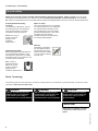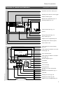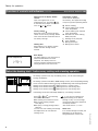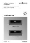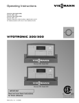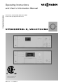
1
Please file in Service Binder
Operating Instructions
and User’s Information Manual
Vitocontrol-S, VD2/CT3/CM2, Model 300-K, MW1
Outdoor-reset logic digital cascade control
VITOCONTROL-S, VD2/CT3/CM2
Certified as a component part
of Viessmann boilers only
5351 341 v1.2 05/2012
Introductory information
For your safety
Please follow these safety instructions closely to avoid the risk of injury to persons and damage to property.
If you smell gas
Don’t smoke! Don’t use naked
flames or cause sparks (e.g. by
switching lights or electrical
appliances on and off)
Open windows and doors
Close the gas shut-off valve
Inform your heating engineers/service
contractors from outside the building
Observe the safety regulations of
your gas supply company (see gas
meter) and those of your heating
engineers (see start-up or instruction
report).
In emergencies
Immediately switch off the power
supply, e.g. at the separate fuse or
power supply disconnect switch
(unless there is a smell of gas).
Close the shut-off valves in the oil
pipes or close the gas shut-off valve,
whichever applicable.
Use suitable extinguishers in the
event of fire.
Work on the equipment
Installation, initial start-up, maintenance
and repairs must be carried out by a
competent person (heating engineer/
service contractor).
Before work is undertaken on the
equipment/heating system, switch off the
power supply voltage (e.g. at the
separate fuse or power supply electrical
isolator switch) and take steps to prevent
it from being switched on again.
Gas-fired systems: Also close the gas
shut-off valve and make secure to
prevent unauthorized use.
Installation of additional components
The installation of additional
components which have not been
tested together with the boiler can
adversely affect the function and
performance of the boiler.
Our warranty does not cover and we
accept no liability for damage
attributable to the installation of such
components.
Boiler room conditions
Do not use a room in which the air
is polluted by halogenated
hydro-carbons (e.g. as contained in
aerosols, paints, solvents and
cleaning agents)
Do not use a room subject to high
levels of dust
Do not use a room subject to
permanently high humidity
The room should be frost-protected
Max. ambient temperature 35 °C/
95 °F.
Provide good ventilation and do not
close or obstruct vents (if installed).
This symbol indicates a
reference to other
instructions which must be
observed.
This header denotes special
Multiinstructions which apply to
boiler
system the use of the Vitotronic 100,
GC1 in a multi-boiler system.
The main controls
The settings required for operating your heating system are made on the
Vitotronic 100, GC1 of each boiler and on the Vitocontrol-S, VD2/CT3/CM2.
If you system is equipped with remote controls, you can also use the remote
controls for some of the settings
See operating instructions for the remote control
5351 341 v1.2
The control unit is behind the hinged cover. The hinged cover is opened by pulling
the top gently downwards towards you.
You must close the hinged cover again after use.
2
Index
Page
Useful tips
Instructions in brief
Reference guide
Introductory information
For your safety . . . . . . . . . . . . . . . . . . . . . . . . . . . . . . . . . . . . . . . . . . . . . . . . . . . . . . . . . . . . . . . . . . . . . . . . . . . . . . . . . . . . . . . . . . . . . . . . . . . . . 2, 4
Ready for operation
The main controls . . . . . . . . . . . . . . . . . . . . . . . . . . . . . . . . . . . . . . . . . . . . . . . . . . . . . . . . . . . . . . . . . . . . . . . . . . . . . . . . . . . . . . . . . . . . . . . 2
Overview of controls and indicators . . . . . . . . . . . . . . . . . . . . . . . . . . . . . . . . . . . . . . . . . . . . . . . . . . . . . . . . . . . 6
Vitotronic 100, GC1
Vitocontrol-S, VD2/CT3/CM2
Selecting the heating circuit - before every setting and scanning
operation (Vitocontrol-S, VD2/CT3/CM2)
Your heating system is preset... . . . . . . . . . . . . . . . . . . . . . . . . . . . . . . . . . . . . . . . . . . . . . . . . . . . . . . . . . . . . . . . . . . . 9
Selecting the heating program (winter, summer) . . . . . . . . . . . . . . . . . . . . . . . . . . . . . . . . . . . 10
Changing the room temperature (Vitocontrol-S, VD2/CT3/CM2) . . 12
Switching on and off
Starting up the heating system . . . . . . . . . . . . . . . . . . . . . . . . . . . . . . . . . . . . . . . . . . . . . . . . . . . . . . . . . . . . . . . . . . . . . 14
Shutting down the heating system . . . . . . . . . . . . . . . . . . . . . . . . . . . . . . . . . . . . . . . . . . . . . . . . . . . . . . . . . . . . . 14
Settings
Changing the boiler water temperature (Vitotronic 100, GC1) . . . . . . . 15
Selecting the time programs (Vitocontrol-S, VD2/CT3,CM2)
Setting the energy saving mode for the holiday period
(Vitocontrol-S, VD2/CT3/CM2)
Resetting the date and time (Vitocontrol-S, VD2/CT3/CM2)
Selecting the language (Vitocontrol-S, VD2/CT3/CM2)
Boiler sequence selection control (Vitocontrol-S, VD2/CT3/CM2)
Changing the heating pattern (Vitocontrol-S, VD2/CT3/CM2)
Scanning
Scanning temperatures and operating status information
Vitotronic 100, GC1
Vitocontrol-S, VD2/CT3/CM2
28
Troubleshooting guide
Diagnosis and correction . . . . . . . . . . . . . . . . . . . . . . . . . . . . . . . . . . . . . . . . . . . . . . . . . . . . . . . . . . . . . . . . . . . . . . . . . . . . . . . . . 31
Vitotronic 100, GC1 . . . . . . . . . . . . . . . . . . . . . . . . . . . . . . . . . . . . . . . . . . . . . . . . . . . . . . . . . . . . . . . . . . . . . . . . . . . . . . . . . . . . . . 31
Vitocontrol-S, VD2/CT3/CM2 . . . . . . . . . . . . . . . . . . . . . . . . . . . . . . . . . . . . . . . . . . . . . . . . . . . . . . . . . . . . . . . . . . . . 33
5351 341 v1.2
Information
.................
3
Introductory information
For your safety
Please ensure that this manual is read and understood before commencing installation. Failure to comply with the issues
listed below and details printed in this manual can cause product/property damage, severe personal injury, and/or loss of
life. Ensure all requirements below are understood and fulfilled (including detailed information found in manual subsections).
Licensed professional heating
contractor
The installation, adjustment, service,
and maintenance of this equipment
must be performed by a licensed
professional heating contractor.
Please see section
entitled “Important
Regulatory and
Installation
Requirements.”
Product documentation
Read all applicable documentation before commencing installation. Store
documentation near boiler in a readily
accessible location for reference in the
future by service personnel.
Advice to owner
Once the installation work is complete,
the heating contractor must familiarize
the system operator/ultimate owner
with all equipment, as well as safety
precautions/requirements, shut-down
procedure, and the need for
professional service annually before
the heating season begins.
Warranty
Information contained in
this and related product
documentation must be
read and followed. Failure
to do so renders warranty
null and void.
For a listing of
applicable literature,
please see section
entitled “Important
Regulatory and
Installation Requirements.”
Safety Terminology
The following terms are used throughout this manual to bring attention to the presence of potential hazards or important product
information. Please heed the advice given!
DANGER
Indicates an imminently hazardous
situation which, if not avoided, will
result in death, serious injury or
substantial product / property damage.
WARNING
Indicates an imminently hazardous
situation which, if not avoided, could
result in death, serious injury or
substantial product / property damage.
CAUTION
Indicates an imminently hazardous
situation which, if not avoided, may
result in minor injury or product /
property damage.
IMPORTANT
5351 341 v1.2
Helpful hints for installation, operation
or maintenance which pertain to the
product.
4
Important Precautions
Safety
Take note of all symbols and notations intended to draw attention to potential hazards or important product information.
These include ”WARNING,” ”CAUTION,” and ”IMPORTANT”. See pages 2 and 4 for details.
Approvals
Viessmann boilers, burners and
controls are approved for sale in North
America by CSA International.
Codes
The installation of this unit shall be in
accordance with local codes. In the
absence of local codes, use:
CSA C22.1 Part 1 and/or local codes
in Canada
National Electrical Code ANSI/NFPA
70 in the U.S.
Always use latest editions of codes.
Working on the equipment
The installation, adjustment, service,
and maintenance of this product must
be done by a licensed professional
heating contractor who is qualified and
experienced in the installation, service,
and maintenance of hot water boilers.
There are no user serviceable parts on
the boiler, burner, or control.
Ensure main power supply to
equipment, the heating system, and all
external controls has been deactivated.
Close main oil or gas supply valve.
Take precautions in both instances to
avoid accidental activation of power
during service work.
For information regarding other
Viessmann System Technology
componentry, please reference
documentation of the respective
product.
We offer frequent installation and
service seminars to familiarize our
partners with our products. Please
inquire.
The completeness and functionality of
field supplied electrical controls and
components must be verified by the
heating contractor. These include low
water cut-offs, flow switches (if used),
staging controls, pumps, motorized
valves, air vents, thermostats, etc.
WARNING
Turn off electric power
supply before
servicing. Contact with
live electric
components can cause
shock or loss of life.
Leave all literature at the installation
site and advise the system operator/
ultimate owner where the literature
can be found. Contact Viessmann for
additional copies.
5351 341 v1.2
Technical literature
Literature applicable to all aspects of
the Vitocontrol S, VD2/CT3/CM2:
- Technical Data Manual
- Installation Instructions
- Service Instructions
- Operating Instructions
- Instructions of other Viessmann
products utilized and installed
- Installation codes mentioned
in this manual
Please carefully read this manual prior
to attempting installation. Any
warranty is null and void if these
instructions are not followed.
5
Ready for operation
Overview of controls and indicators
Vitotronic 100, GC1
Manual override
Changing the boiler water temperature
(without function in multi-boiler system)
Changing the domestic hot water
temperature (without function in multiboiler system) (see pg.21)
Value selector buttons
Information
Confirmation button
Factory settings (see below)
Display window
Heating program selector buttons
w without function in multi-boiler
system (see pg. 10)
Adjustable high limit
Manual reset fixed high limit
TÜV
Power on/off switch (see pg. 14)
Fuse F1, F2
TÜV (for service purposes only)
Operating status indicator (green)
Fault indicator (red)
Flashing data
Data flashing in the display window
means that new settings can be
entered.
6
Other display symbols
(These are not displayed continuously,
but appear according to system type
and operating status)
8 Digital display of the
corresponding value
°C
Unit of measurement for
temperature values
h
Unit of measurement for display
of burner hours run
U
Fault message
r Central heating ON
rp Displayed when output sÖ is
activated
A
w
Burner ON
Domestic hot water heating
released
wp DHW pump (circulation pump
for heating the DHW tank) ON
|
Scan hours run
1st stage burner
||
Scan hours run
2nd stage burner
||| Scan number of burner starts
|||| Consumption
5351 341 v1.2
Factory settings
Press this button to reset all altered
values to their factory settings. Please
note that all altered values are reset to
the factory settings.
Ready for operation
Overview of controls and indicators
Vitocontrol-S, VD2/CT3/CM2
Emissions test switch (see pg. 34)
Heating circuit selector buttons (pg.8)
Display window (pg.8)
Normal room temperature (pg. 11)
Heating programs (pg. 10)
Boiler sequence
1-23-4
Control on/off switch (pg. 14)
Fuse F1
Energy saving mode (pg. 13)
Party mode (pg. 12)
Hinged cover of programming unit
Operating status indicator (green)
Fault indicator (red)
Time program for central heating
(pg. 16)
Boiler sequence
Time program for domestic hot water
heating (pg. 18)
1-23-4
Other symbols (pg.8)
Time program for DHW re-circulation
pump (pg. 15)
Holiday program (pg. 21)
Information
Confirmation
Factory settings
Setting buttons
Domestic hot water temperature
(pg. 21)
Reduced room temperature (pg. 11)
5351 341 v1.2
Time/date
Heating curve shift (pg. 26)
Heating curve slope (pg. 26)
Hinged cover of propgramming unit
7
Ready for operation
Overview of controls and indicators (continued)
Adjustment of the display window
contrast
Open the hinged cover on the
programming unit, and press
and,
at the same time, adjust the contrast
with the
or
button.
Factory settings
Press this button to reset all altered
values to their factory settings. Please
note that all altered values are reset to
the factory settings.
Flashing data
Data flashing in the display window
means that new settings can be
entered.
Boiler sequence
1-23-4
Vitocontrol-S, VD2/CT3/CM2
Other display symbols
(These are not displayed
continuously, but appear according
to system type and operating status)
e Risk of freezing
s Central heating with normal
room temperature
m Central heating with reduced
room temperature
w Domestic hot water heating,
DHW pump ON
p Heating circuit pump ON
U
Fault message
V Mixing valve open
v Mixing valve closed
Basic display
The basic display of the Vitocontrol-S,
VD2/CT3/CM2 shows the boiler
sequence. The display reverts to
showing the boiler sequence after each
setting is made on the control unit.
Select the heating ciruit - before every setting and scanning operation
Boiler temperature
On heating systems with only one heating circuit, you can start making all
settings immediately.
Mo
On heating systems with two or three heating circuits, the corresponding heating
circuit must be selected before carrying out each setting and scanning operation.
Heating circuit selector button : Heating circuit 1 (system circuit)
Heating circuit selector button : Heating circuit 2 with mixing valve
Heating circuit selector button 3 : Heating circuit 3 with mixing valve
The heating circuits are individually labelled by your heating contractor.
8
If you have not selected the
required heating circuit before
starting to carry out the settings,
the following instruction appears in
the display window:
“First select button 1, 2 or 3.”
Please note:
If no further settings are made, the
illumination of the buttons is
extinguished after a short time.
5351 341 v1.2
Press
or
or 3 ; the following
buttons are illuminated:
the heating circuit selector button
the current heating program
(see page 8)
the party or energy saving mode, if
selected
You can now start making the settings
and adjustments for the selected
heating circuit.
Ready for operation
Your heating system is preset ...
Vitocontrol-S, VD2/CT3/CM2
The control units are preset in the factory to a standard operating mode. The
heating system, therefore, is ready for operation.
You can change the factory settings to suit your individual preferences.
Vitotronic 100, GC1
Heating Program
The heating program is set for
“Central heating and domestic hot
water”, i.e. heating takes place,
controlled via the Vitocontrol-S, VD2/CT3/CM2.
Vitocontrol-S, VD2/CT3/CM2, Model 300-K MW1
Date and time (CET)
The date and time are preset in the
factory. Resetting for winter/summer
time takes place automatically.
Heating program
The heating program is set for
“Central heating and domestic hot
water”, i.e. central heating and
domestic hot water heating
(if a DHW tank is installed)
take place, in accordance with the
time programs.
5351 341 v1.2
Time program
Between 06:00 and 22:00 hrs, central
heating takes place with the normal
room temperature and, between 05:30
and 22:00 hrs, domestic hot water
heating (if a DHW tank is installed).
9
Ready for operation
Selecting the heating program (winter, summer)
Vitotronic 100, GC1
Select the required heating program
with the
,
or button.
When pressed, the corresponding
button is illumintaed
Central heating and domestic hot water
The boiler is available to the heating
system and is switched on according
to demand and in accordance with
the boiler sequence
Frost protection of the boiler
Domestic hot water only
Without function
The domestic hot water supply is
always controlled via the
Vitocontrol-S, VD2/CT3/CM2
(see below)
Standby operation
The boiler is switched off and is no
longer availble to the Vitocontrol-S,
VD2/CT3/CM2 (i.e. drops out of the
boiler sequence)
Frost protection of the boiler
Please note:
The circulation pump is switched
on for a short time every 24 hours
to prevent them from seizing up.
Vitocontrol-S, VD2/CT3/CM2,
Model 300-K MW1
1.Press the heating circuit selector
button; the button is illuminated
Central heating and domestic hot water
Central heating with alternating
normal and reduced room
temperature (frost protection)
according to the selected time
program.
Domestic hot water supply (if a DHW
cylinder is installed) and DHW
circulation pump (if installed) ON
according to selected time program
Frost protection of the DHW cylinder
Domestic hot water only
No central heating
Domestic hot water supply (if a DHW
cylinder is installed) and DHW
circulation pump (if installed) ON
according to selected time program
Frost protection of the DHW cylinder
Standby operation
No central heating
No DHW supply
10
The selected heating program
appears in the display window
for a short time.
Example
For the winter transitionary periods.
Please note:
When the button is lit, the “ ”
symbol appears in the display
window during central heating with
the normal room temperature; the
“ ” symbol is illuminated during
central heating with a reduced room
temperature higher than 3°C / 37°F
Example
For the summer.
Please note:
DHW cylinder is connected,
“without function” is displayed.
Please note:
The circulation pumps are switched
on for a short time every 24 hours
to prevent them from seizing up.
5351 341 v1.2
2.Select the heating program with the
,
or button.
Ready for operation
Selecting the heating program (winter, summer)
Vitocontrol-S, VD2/CT3/CM2
In the ”Central heating and domestic hot water” heating program, central heating
takes place with alternating ”normal room temperature” and ”reduced room
temperature” according to the selected time program.
You can set the required room temperature as follows:
To change the ”normal room temperature” (day temperature)
Normal room temp.
ºC
Factory setting:
20ºC / 68ºF from 06:00 to 22:00 hrs.
The ”normal room temperature” can be
set between 3 and 37ºC /
37 and 99ºF.
1.Press the heating circuit selector
button; the button is illuminated.
2.Set the required temperature value
with the “ts” selector knob.
The display changes after a short
time and shows the boiler sequence.
To change the ”reduced room temperature” (night temperature)
Reduced room temp.
ºC
Factory setting:
Frost protection 3ºC / 37ºF from 22:00
to 06:00 hrs.
The “reduced room temperature” can
be set between 4 and 37ºC / 39 and
99ºF.
1.Open the hinged cover on the
programming unit.
2.Press the heating circuit selector
button; the button is illuminated.
Press
; the previous
temperature setting flashes
in the display window.
3.
4.
5351 341 v1.2
5.
/
Press the
/
button
until the required
temperature value appears.
Please note:
If the temperature value
3ºC / 37ºF is selected ,
“frost protection” appears in the
display window.
Confirm by pressing
;
the temperature value stops
flashing and is stored.
The display changes and
shows boiler sequence.
6. Close the hinged cover on the
programming unit.
11
Ready for operation
Setting the party mode
Vitocontrol-S, VD2/CT3/CM2
Switch on the party mode when you require central heating and domestic hot
water (if a DHW tank is installed) for a short time independently of the preset
heating and time program.
To activate the party mode
1. Open the hinged cover on the
programming unit.
2. Press the heating circuit selector
button; the button is illuminated.
Party mode
3.
ºC
Press ; the button is
illuminated, the party mode
display appears in the display
window and the party temperature value flashes.
The light on the button turns off
after approx. 1 minute. The party
mode is still active.
4. To change the party temperature:
/
Press the
/
button until
the required temperature
value appears.
5.
Confirm by pressing
; the
temperature value stops
flashing and is stored.
The display changes and
shows the boiler
temperature.
6. Close the hinged cover on the
programming unit.
To cancel the party mode
5351 341 v1.2
The party mode is cancelled the next
time the preset heating program
switches automatically to central
heating with the ”normal room
temperature”.
If you want to cancel the party mode
immediately, press the heating circuit
selector button and the
button
again; the button is no longer
illuminated.
12
Ready for operation
Activating the energy saving mode
Vitocontrol-S, VD2/CT3/CM2
The energy saving mode is only possible in the ”rw“ heating program. Switch
on the energy saving mode when you require particularly economic central
heating for a short time. In the energy saving mode the preset room temperature
is automatically lowered.
To activate the energy saving mode
1. Press the heating circuit selector
button; the button is illuminated.
Energy saving mode
2.
Press
; the button is
illuminated, the energy saving
mode display appears in the
display window for a short
time.
The light on the button turns off
after approx. 1 minute. The
energy saving mode is still active.
To cancel the energy saving mode
5351 341 v1.2
The energy saving mode is cancelled
automatically the next time the
preset heating program switches to
central heating with the ”reduced
room temperature”.
If you want to cancel the energy
saving mode immediately, press the
heating circuit selector button and
the
button again; the button is no
longer illuminated.
13
Switching on and off
Starting up the heating system
Vitocontrol-S, VD2/CT3/CM2
The initial start-up and matching of the control unit to local conditions and the
structural characteristics of the building must be carried out by your heating
contractor.
1. Check the pressure of the heating
system on the manometer.
If the needle is below the red
marker, the system pressure is too
low – in which case add more water
or contact your heating contractor.
2. Open the shut-off valves in the oil
pipes (at the boiler) or open the gas
shut-off valve, whichever is
applicable.
3. Switch on the power supply voltage,
e.g. at the separate fuse or a power
supply disconnect switch.
4. Switch on the heating system
on/off switch ”8”; the operating
status is indicated by the green lamp
and, after a short time, the boiler
temperature appears in the display
window.
Shutting down the heating system
Your heating system is
installed and the remote controls are
now ready for operation.
Vitocontrol-S, VD2/CT3/CM2
If you do not want to use your heating system temporarily, select standby
operation on the Vitocontrol-S, VD2/CT3/CM2 (see “Selecting the heating
program”).
If you want to switch off only one boiler in the heating system, select standby
operation on the corresponding Vitotronic 100, GC1.
If you do not want to use your heating system for a long period (several months),
you should shut down the system.
We advise you to contact your heating contractor before and after shutting down
the heating system for long periods. Your heating contractor will take any
necessary action, e.g. for frost protection of the system or to safeguard the heat
exchange surfaces.
2. Close the shut-off valves in the oil
pipes (at the tank and filter) or close
the gas shut-off valve, whichever is
applicable.
3. Switch off the main power supply,
e.g. at the separate fuse or a main
electrical isolator switch. The power
supply to the system is now
14
The green lamp (operating status
indicator) goes out.
switched off. There is no frost
protection.
Please note:
The settings of the control unit
remain intact.
5351 341 v1.2
1. Switch off the heating system
on/off switch ”8” on all control
units.
Settings
Changing the boiler water temperature
Vitotronic 100, GC1
In a multi-boiler system with the Vitocontrol-S, VD2/CT3/CM2, the boiler water
temperature is determined by the Vitocontrol-S, VD2/CT3/CM2 for all boiler
control units.
It is not possible to make the setting on the Vitotronic 100, GC1.
Selecting the time programs
Vitocontrol-S, VD2/CT3/CM2
You can select time programs for central heating, domestic hot water (if a DHW
tank is installed) and the DHW re-circulation pump (if installed). The DHW
re-circulation pump ensures that hot water is available at the taps when required.
A time program consists of 4 time phases, i.e.
The central heating can be switched up to 4 times per day to and fro between
the ”normal room temperature” and the ”reduced room temperature”.
The domestic hot water supply and DHW re-circulation pump can be switched
on and off up to 4 times per day.
Time phase 1 is preset in the factory for all days of the week, i.e. during this
time central heating takes place with the normal room temperature, domestic
hot water heating takes place and the DHW re-circulation pump is switched on.
The following buttons are assigned to the time programs:
Button
Time program for
Factory setting
ur
central heating
normal room temperature:
6.00 to 22.00 hrs
uw
domestic hot water
ON:
5.30 to 22.00 hrs
up
DHW re-circulation pump
ON:
5.30 to 22.00 hrs
You can set identical time programs for all days of the week or individual time
programs for each day of the week.
5351 341 v1.2
When setting the time programs, please take into account the reaction time of
the heating system. Therefore choose correspondingly earlier starting and
finishing times.
15
Settings
Selecting the time programs
(continued)
Vitocontrol-S, VD2/CT3/CM2
Changing and scanning the time program for central heating
11. Open the hinged cover on the programming unit.
12. Press the heating circuit selector
button; the button is illuminated.
Press
; the ”Central heating time program” display
appears in the display window.
13.
14.
/
Time Prog. Central Htg.
1-7
Press
/
until one of
the following displays appears in the display window:
”1-7” if you wish to set
identical time phases for
all days of the week.
Please note:
If different time phases are set for
individual days of the week and
you would like to set the same time
phases for all days again, press
when the display ”1-7” is showing.
All time phases are reset to their
factory settings.
or
Mo”, ”Tu” etc. if you
wish to set different time
phases for the displayed
day of the week.
Time Prog. Central Htg.
Mo
15.
Press
to confirm; the display changes to ”Central heating time phase 1”.
16.
Press
; the display changes to ”Central heating
phase 1 ON”.
/
10.
to skip a time phase.
Press
/
until the required starting time of the central heating phase appears.
Press
to confirm; the display changes to ”Central heating phase 1 OFF”.
18.
19.
Press
/
Press
/
until the required finishing time of the
central heating phase appears.
Press
to confirm; the
display changes to ”Central
heating phase 2 ON”.
11. To set the start and end of central
heating phases “2” to “4”, follow
the procedure described in points 7
to 10.
12. Close the hinged cover on the programming unit.
After you have confirmed the
finishing timer of central heating
phase 4 with
, the display
changes and shows the boiler
sequence.
5351 341 v1.2
17.
16
If you wish to exit the time
program setting mode, press
again.
Settings
Selecting the time programs
(continued)
Vitocontrol-S, VD2/CT3/CM2
Changing and scanning the time program for central heating (continued)
To exit the setting mode at any time
1.
Press
; the display changes to ”Exit? Yes”.
2.
Press
to confirm; the display changes and shows the
boiler temperature.
To scan the time phases
Follow the procedure described on
page 13, but without using the
and
buttons.
The time phases at a glance
1. Open the hinged cover on the
programming unit.
2. Press the heating circuit selector
button; the button is illuminated.
1
0
3
6
9
12 15 18 21 24
1-7
3. Press
and
simultaneously;
the preset time phases appear on a
time slot graphic.
4. Close the hinged cover on the programming unit.
To erase the time phases
1. Open the hinged cover on the programming unit.
2. Press the heating circuit selector
button; the button is illuminated.
Central Htg. Phase 2 OFF
3.
Press
; the ”Central heating time program” display appears in the display window.
4.
Press
until the required
”Central heating phase OFF”
appears.
5.
Press
until the display
”– – : – –” appears for the
finishing time.
6.
Press
to confirm until the
display changes and shows
the boiler temperature.
5351 341 v1.2
1-7
7. Close the hinged cover on the programming unit.
17
Settings
Selecting the time programs
Vitocontrol-S, VD2/CT3/CM2
(continued)
Changing and scanning the time program for domestic hot water heating and the DHW re-circulation pump
The automatic mode is selected in the time program for domestic hot water and
the DHW re-circulation pump, i.e. domestic hot water heating takes place in
parallel with the central heating time program, but starts 30 minutes earlier.
The DHW re-circulation pump runs parallel with the domestic hot water time
program.
If you do not require the automatic mode, you can also set individual time programs.
The following example shows the steps required for setting a time program for
domestic hot water heating. Follow the same steps when setting the time
program for the DHW re-circulation pump.
To select the automatic mode
(if required)
1. Open the hinged cover on the programming unit.
2. Press the heating circuit selector
button; the button is illuminated.
Press
; the ”DHW time
program” display appears in
the display window.
3.
4.
5.
/
Press
/
for ”Automatic?” if ”Automatic?” is not
already shown in the display
window.
Press
to confirm.
To set an individual time program
1. Open the hinged cover on the programming unit.
2. Press the heating circuit selector
button; the button is illuminated.
18
Press
; the ”DHW time
program” display appears in
the display window.
4.
Press
/
for ”Individual?” if ”Individual?” is not
already shown in the display
window.
5.
Press
to confirm.
If you wish to exit the time
program setting mode, press
again.
5351 341 v1.2
3.
Settings
Selecting the time programs (continued)
Vitocontrol-S, VD2/CT3/CM2
Changing and scanning the time program for domestic hot water heating and the DHW re-circulation pump (continued)
16.
/
Time prog. DHW
1-7
Press
/
until one of
the following displays appears in the display window:
”1-7” if you wish to set
identical time phases for
all days of the week.
Please note:
If different time phases are set for
individual days of the week and
you would like to set the same
time phases for all days again,
press
when the display ”1-7”
is showing. All time phases are
reset to their factory settings.
or
”Mo”, ”Tu” etc. if you
wish to set different time
phases for the displayed
day of the week.
Time prog. DHW
Mo
17.
Press
to confirm; the
display changes to ”DHW
time phase 1”.
18.
Press
; the display changes to ”DHW phase 1 ON”.
19.
/
12.
to skip a time phase.
Press
/
until the required starting time of the
DHW phase appears.
Press
to confirm; the
display changes to ”DHW
phase 1 OFF”.
10.
11.
Press
/
Press
/
until the required finishing time of the
DHW phase appears.
Press
to confirm; the
display changes to ”DHW
phase 2 ON”.
13. To set the start and end of DHW
phases 2 to 4, follow the procedure
described in points 9 to 12.
After you have confirmed the last
input with
, the display changes
and shows the boiler temperature.
14. Close the hinged cover on the programming unit.
5351 341 v1.2
To exit the setting mode at any time
1.
Press
; the display
changes to ”Exit? Yes”.
2.
Press
to confirm; the
display changes and shows
the boiler sequence.
19
Settings
Selecting the time programs
(continued)
Vitocontrol-S, VD2/CT3/CM2
Changing and scanning the time program for domestic hot water heating and the DHW re-circulation pump (continued)
To scan the time phases
Follow the procedure described on
page 15 and 16, but without using the
and
buttons.
The time phases at a glance
1. Open the hinged cover on the programming unit.
2. Press the heating circuit selector
button; the button is illuminated.
1
0
3
6
9
12 15 18 21 24
1-7
3. Press w and
simultaneously;
the preset time phases appear on a
time slot graphic.
4. Close the hinged cover on the programming unit.
To erase the time phases
1. Open the hinged cover on the programming unit.
2. Press the heating circuit selector
button; the button is illuminated.
3.
Press
; the ”DHW time
program” display appears in
the display window.
4.
Press
until the required
”DHW phase OFF” appears.
5.
Press
until the display
”– – : – –” appears for the finishing time.
6.
Press
to confirm until the
display changes and shows
the boiler temperature.
DHW Phase 2 OFF
1-7
Domestic water heating on a one-off basis outside the programmed time
phases
Press
20
twice 2 to 3 seconds apart.
5351 341 v1.2
7. Close the hinged cover on the programming unit.
Settings
Changing the domestic hot water temperature
Vitocontrol-S, VD2/CT3/CM2
In a multi-boiler system the
Vitotronic 100, GC1 is without function. The
domestic hot water temperature is set on the Vitocontrol-S, VD2/CT3/CM2.
1. Open the hinged cover on the
programming unit.
Desired DHW temp.
ºC
Press
; the previous
temperature setting flashes
in the display window.
12.
13.
14.
/
Press the
/
button until the required temperature
value appears.
Confirm by pressing
;
the temperature value stops
flashing and is stored.
The display changes and
shows the boiler
temperature.
15. Close the hinged cover on the programming unit.
Setting the energy saving mode for the holiday period
Vitocontrol-S, VD2/CT3/CM2
If you want to set the heating system to the minimum energy consumption,
e.g. while you are away on holiday, choose the holiday program or the standby
mode.
Holiday program
5351 341 v1.2
When the ”rw” heating program is
set, central heating takes place during the holiday program with the selected ”reduced room temperature”,
but without domestic hot water heating.
The preset time program for central
heating and domestic hot water is
active on the dates of your departure
and return.
Please note:
The control unit is set up so that
the holiday program is effective
for all heating circuits.
If you require this to be changed,
please contact your heating
contractor.
When the ”w” heating program is
set, only frost protection of the
heating system takes place during the
holiday program. Domestic hot water
takes place according to the preset
heating program on the dates of your
departure and return.
21
Settings
Setting the energy saving mode for the holiday period
(continued)
Vitocontrol-S, VD2/CT3/CM2
1. Open the cover on the programming
unit.
2. Press the heating circuit selector
button; the button is illuminated.
3.
Press ; the ”Holiday program” display appears in the
display window.
4.
Press
; the display
changes to the ”Departure
date” (actual day of the
week).
Departure date
Fr
5.
/
Tu
8.
Press
/
until the
required departure date
appears.
Press
to confirm;
the display changes to the
”Return date” (the return
date shown is the day
following the entered
departure date).
6.
Return date
7.
If you want to erase the holiday
program during the setting
procedure, press
again and
confirm ”Erase? Yes” with
.
/
Press
/
until the
required return date
appears.
Press
to confirm;
the display changes and
shows the boiler
temperature.
9. To set the temperature for the
duration of the holiday program
(only in the ”rw” heating
program):
Press
.
Set the required value with the
or
button.
Confirm by pressing
; the
temperature value stops flashing
and is stored.
This temperature also applies to
the reduced room temperature
outside the holiday program.
10. Close the hinged cover on the
programming unit.
22
If you want to cancel the holiday
program before the selected return
date, press
again and confirm
“Erase? Yes” with
.
5351 341 v1.2
After the departure date, ”Holiday program” and the actual date appear in
the display window.
On the return date, the boiler temperature appears in the display window.
Settings
Resetting the date and time
Vitocontrol-S, VD2/CT3/CM2
The time and date are preset in the factory and can be changed manually.
There is no need for manual resetting in conjunction with a radio clock receiver
(accessory).
1. Open the hinged cover on the programming unit.
Time
Press
; the ”Time” appears in the display window.
2.
3.
/
Press
to confirm;
the display changes and
shows the ”Date”.
4.
DDate
5.
We
6.
Press
/
until the
required time appears.
/
Press
/
until the required date appears.
Press
to confirm;
the display changes and
shows the boiler temperature.
7. Close the hinged cover on the programming unit.
Selecting the language
Vitocontrol-S, VD2/CT3/CM2
1. Open the hinged cover on the programming unit.
2. Press the heating circuit selector
button; the button is illuminated.
Participant No.
3.
Press
; the ”Participant
No.” appears in the display
window.
4.
Press
until the required
language appears.
5.
Press
to confirm;
the display changes and
shows the boiler temperature.
ºC
i
English
5351 341 v1.2
i
6. Close the hinged cover on the programming unit.
23
Settings
Boiler sequence selection control
Boiler sequence
1-23-4
Boiler sequence
12 34
Vitocontrol-S, VD2/CT3/CM2
Actual boiler sequence
The digits shown in the basic display show the boiler numbers of the connected
boilers in the current actual boiler sequence.
The hyphens between the boiler numbers indicate the status of each boiler.
The boilers in front of the first hyphen are those which are activated by the
Vitocontrol-S, VD2/CT3/CM2.
The boilers between the two hyphens are available for central heating
purposes, but are not currently required.
The boilers which are blocked (i.e. which are not available to the Vitocontrol-S,
VD2/CT3/CM2 for generating heat, e.g. due to a fault) appear after the second
hyphen.
Alternative, operator-requested boiler sequence
The boiler sequence criteria (e.g. fixed lead boiler, last boiler) are set on the
Vitocontrol-S, VD2/CT3/CM2 by your heating contractor during start-up of the
heating system. Using the boiler sequence on the basis of all criteria, it is possible
that
no alternative boiler sequence is available.
1. Open the hinged cover on the
programming unit.
2.
3.
4.
/
Press / ; for approx. 2
seconds; the alternative,
operator-requested boiler
sequence (shown without
hyphens) appears in the
display window.
/
Press
/
until the
required boiler sequence
appears.
Press
to confirm;
the display changes and
shows the actual boiler
sequence.
Please note:
The operator-requested boiler
sequence does not have to
correspond to the actual boiler
sequence. The actual boiler
sequence is dependent on various
factors (e.g. faults) and the
settings made by your heating
contractor (e.g. temperaturedependent blocking).
5351 341 v1.2
5. Close the hinged cover on the
programming unit.
24
Settings
Changing the heating pattern
Vitocontrol-S, VD2/CT3/CM2
The heating pattern of the boiler is influenced by the outdoor temperature and
the settings of the ”shift” and ”slope” of the ”heating curve”. Heating curves
represent the relationship between the outdoor temperature and the boiler
water or supply temperature. Put simply: the lower the outdoor temperature,
the higher the boiler water or supply temperature.
You can change the setting of the heating curve if you establish, over a prolonged
period during the heating season, that the room temperature does not meet your
requirements.
Please observe the difference in the heating pattern over a sufficiently long
period before altering the settings again.
Short-term changes in the room temperature are carried out with the ”ts”
selector knob or with the ”tm” button.
Please note:
In the factory settings, the slope is set to 1.4 and the shift to 0.
The heating curves shown apply to the following settings:
”Shift of heating curve” = 0
With a different shift setting, the curves are shifted parallel in a vertical direction.
”Normal room temperature “s” = approx. 20°C / 68°F.
Slope
5351 341 v1.2
The slope of the heating curve is normally within the range marked
A for underfloor heating systems,
B for modulating heating systems,
C for heating systems with boiler
water temperatures over 75°C /
167 °F.
Examples
Well insulated house in protected
position (radiator heating):
Slope = 1.2
House in exposed position or
with old heating system
(radiator heating):
Slope = 1.6
25
Settings
Changing the heating pattern
Vitocontrol-S, VD2/CT3/CM2
Changing the heating pattern
1. Open the hinged cover on the programming unit.
2. Press the heating circuit selector
button; the button is illuminated.
Slope
4.
Shift
Press
or
Press
3.
5.
/
for ”Slope”
for ”Shift”.
As a guide, please refer to the
table headed ”Change heating
pattern if...” on page 25.
Press
/
until the
required value is displayed.
Press
to confirm;
the display changes and
shows the boiler temperature.
5351 341 v1.2
6. Close the hinged cover on the
programming unit.
26
Settings
Changing the heating pattern
(continued)
Change heating pattern if ...
Action
... not enough heat is generated in
the cold season
Adjust the slope of the heating
curve upwards by one increment
... too much heat is generated in the
cold season
Adjust the slope of the heating
curve downwards by one increment
... not enough heat is generated at
transitionary times of the year and
in the cold season
Adjust the shift of the heating curve
to a higher value (e.g.+3 K)
... too much heat is generated at
transitionary times of the year and
in the cold season
Adjust the shift of the heating curve
to a lower value (e.g. -3 K)
... not enough heat is generated at
transitionary times of the year but
adequate in the cold season
Adjust the slope of the heating
curve downwards by one increment,
and the shift to a higher value
(e.g.+3 K).
Vitocontrol-S, VD2/CT3/CM2
Example
Slope
Slope
Shift
Shift
Slope
Shift
... the boiler water temperature is
too high at transitionary times of
the year, but adequate in the cold
season
Adjust the slope of the heating
curve upwards by one increment,
and the shift to a lower value
(e.g. -3 K).
Slope
5351 341 v1.2
Shift
27
Scanning
Scanning temperatures and operating status information
Vitotronic 100, GC1
You can scan various actual temperatures and operating status information
depending on the system components connected:
Data
displayed
Meaning
Please note
0__01
LON participant number
Equipment number within the
LON system
3__65.°C
Boiler water temperature
––
6__45.°C
Return temperature at aJA
(1st return temperature
sensor)
Only displayed if temperature
sensor of Therm-Control
or
temperature sensor T1
connected
8_190.°C
Flue gas temperature
Only displayed if flue gas
temperature sensor connected
9__50.°C
Return temperature at aJB
(2nd return temperature
sensor)
Only displayed if temperature
sensor T2 connected
|
Burner hours run
1st stage
The hours run can be reset to
”0” by pressing D.
The hours run displayed are approximate values only.
Burner hours run
2nd stage
The hours run can be reset to
”0” by pressing D.
The hours run displayed are approximate values only.
Burner starts
The number of burner starts can
be reset to ”0” by pressing D.
03572.h
||
00572.h
|||
30417.
Press
; the first temperature appears in the display
window.
1.
60
0_...61
°C
2.
Press
/
to scan other
data (see table above).
Press
to exit the scanning
mode.
The display changes and
shows the boiler water
temperature.
5351 341 v1.2
3.
/
28
Scanning
Scanning temperatures and operating status information
Vitocontrol-S, VD2/CT3/CM2
You can scan various actual temperatures and operating status information
depending on the system components connected and the settings made.
Participant no.
Holiday program
with dates of departure and return
Holiday program active
Current Outdoor temperature
Boiler sequence
Common supply temperature
Current boiler temperature for each
boiler (1-4)
Flue gas temperature
Sensor aJA
Sensor aJB
Current domestic hot water temperature
– DHW temperature 1
– DHW temperature 2
Current supply temperature
Current room temperature for each
heating circuit
Time
Date
Output 20 ON/OFF
Output 29 ON/OFF
Output 52 Open/Closed
DHW pump ON/OFF
DHW re-circulation pump ON/OFF
Heating circuit pump ON/OFF
Mixing valve Open/Closed
Solar pump ON/OFF
Solar pump run hours
Various languages
iParticipant No.
5351 341 v1.2
i
°C
1. Open the hinged cover on the programming unit.
2. Press the heating circuit selector
button; the button is illuminated.
3.
Press
; the ”Participant
No.” appears in the display
window.
4.
/
Press
/
to scan other data.
5.
Press
to exit the scanning
mode.
The display changes and
shows the boiler temperature.
6. Close the hinged cover on the programming unit.
Equipment number within the
LON system
if entered
if holiday program is activated
if sensor installed
if sensor installed
if sensor installed
if sensor installed
if 2 DHW tank temperature
sensors are connected
for mixing valve circuit M2 and
M3, if sensor connected
if Vitotrol remote control installed
The language required for
permanent use in the display can
button.
be selected with the
To scan the heating program, party or
energy saving mode
Press the heating circuit selector
button;
The button on the active program is
illuminated.
29
Troubleshooting guide
Special displays
Vitocontrol-S, VD2/CT3/CM2
Please contact your heating contractor
to arrange a service call.
MService
Mo
°C
Remote control
It is not possible to make settings on
the control unit, only on the remote
control.
Example
”Normal room temperature” on
the ”ts” selector knob can only
be set on the remote control.
Without function
This display flashes when you have
pressed a button to which no function
is assigned.
Example
if no DHW tank is connected.
Ext. control
Changeover of the heating program
The heating program which is set on
the control unit has been switched over
by an external control.
Slab curing
If the slab curing function is coded, this
display appears until the function is
terminated.
The setting of the heating and holiday
program is accepted by the heating circuit for which ”centralized operation”
has been coded by your heating
contractor.
5351 341 v1.2
Centralized operation
30
Troubleshooting guide
Diagnosis and correction
Vitotronic 100, GC1
If a fault occurs on a boiler, it will be indicated in the display window and by
the flashing red fault lamp.
In the display window you can read off the fault code yourself and inform your
heating contractor accordingly.
1.
/
_1...38.U
Press
/
to display the
individual fault codes if several faults have occurred
simultaneously.
Press
to confirm;
the display changes and
shows the boiler temperature.
2.
Please note:
The fault message will re-appear
on the following day if the fault is
not corrected in the meantime.
The red fault lamp continues to
flash until the fault has been
corrected.
To call up an acknowledged fault message
Press
for approx. 2
seconds.
1.
2.
/
The fault code is displayed.
Press
/
to display the
individual fault codes if
several faults have occurred
simultaneously.
Cause
Remedy
The boiler does not start up
Heating system switch ”8”
Switch on
Electrical isolator switch, if installed,
is switched off
Switch on electrical isolator switch
Fuse in the domestic power circuit or
in the control unit has blown or
tripped
Inform heating contractor
No heat request made via the
Vitocontrol-S, VD2/CT3/CM2
Check the setting on the
Vitocontrol-S, VD2/CT3/CM2
5351 341 v1.2
Fault
31
Troubleshooting guide
Diagnosis and correction
Burner does not switch on
Vitotronic 100, GC1
Heating program ”9” is set (the
corresponding button is illuminated)
Set ”rw” heating program
(page 10)
Vitoair draught stabilizer defective
(only on boilers with pressure jet
burner)
Inform heating contractor.
Change setting of Vitoair to
manual operation:
Press in rotary knob A on
motor and turn fully beyond
setting ”4”.
A
Failure of motor-controlled flue gas
damper (only on gas boilers with atmospheric burner)
Inform heating contractor.
Change setting of motor-controlled
flue gas damper to manual operation:
Press in rotary knob A on motor and
turn fully beyond setting ”4”.
Fault on control unit
After consulting your heating contractor, the boiler can be operated
temporarily with constant boiler
water temperature by turning the
emissions test switch ”S” to ”h”;
leave cover open.
No fuel
Oil or LPG:
Check fuel supply and re-order if
necessary.
Natural gas:
Open gas-shut off valve or contact
gas supply company if necessary.
Burner does not start; red fault indicator flashes on the control unit and
red fault lamp is illuminated on the
burner
Faulty start of burner
Make a new attempt to start by
pressing the reset button
On the front of the burner hood
with pressure jet burners,
On the front panel of the boiler
with atmospheric burners.
If the burner still fails to operate
after pressing the reset button,
check the points stated in the section headed ”Starting up the heating
system” and then press the reset
button again.
If the burner still fails to switch on,
contact your heating contractor.
Fault symbol ”U” appears in the display window with flashing fault code
Fault on heating system
Make a note of the fault code and
inform your heating contractor
32
5351 341 v1.2
A
Troubleshooting guide
Diagnosis and correction
DFault
°C
Vitocontrol-S, VD2/CT3/CM2
If a fault occurs on the heating system, it will be indicated in the display
window and by the flashing red fault lamp.
Using the scan facility, you can read off the fault code yourself and inform your
heating contractor accordingly.
Tu
1. Open the hinged cover on the programming unit.
Outdoor sensor
Press
for fault search.
The error source is displayed in plain language and
in the form of a fault code.
2.
U
Example
U Fault display
1
Error number
1
Sensor designation
plug designation
Open circuit
or
Short circuit
Acknowledge? Yes
Press
; the display changes to ”Acknowledge?
Yes”.
3.
4.
/
Press
”No”.
/
for ”Yes” or
Press
to confirm;
the display changes and
shows the boiler temperature.
5.
Press ”Acknowledge?” to confirm
that you have noted the fault.
Please note:
The fault message will re-appear
at 7.00 hrs on the following day if
the fault is not corrected in the
meantime.
The red fault lamp continues to
flash until the fault has been
corrected.
6. Close the hinged cover on the programming unit.
To call up an acknowledged fault message
1.
/
The fault is displayed.
Press
/
to display
further faults.
Only if two or more faults have
occurred.
5351 341 v1.2
2.
Press
for approx.
2 seconds.
33
Troubleshooting guide
Diagnosis and correction
(continued)
Vitocontrol-S, VD2/CT3/CM2
Fault
Cause
Remedy
Heating circuit does not start up
Heating system switch ”8”
Switch on
Power supply disconnect switch, if
installed, is switched off
Switch on power supply disconnect
switch
Heating program ”9” is set (corresponding button is illuminated)
Set ”rw” or “w“ heating program
(page 10)
Fuse in the domestic power circuit
or in the control unit has blown or
tripped
Inform heating contractor
Fault on control unit
After consulting your heating contractor, the boiler can be operated
temporarily with constant boiler
water temperature by turning the
override switch ”S” to ”h”; leave
cover open
Control unit incorrectly programmed
or set
Check time program for domestic
hot water heating, check domestic
hot water temperature, and correct
if necessary
DHW tank temperature sensor or
re-circulation pump for the DHW
tank is defective
Inform heating contractor
Time incorrectly set
Set correct time
Heating program ”w” or ”9” is set
(corresponding button is illuminated)
Set heating program ”rw”
(page 6)
Burners are operating, but no hot
water (only on systems with DHW
tank)
The rooms are cold even though the
burners are operating
Operation with domestic hot water
tank only:
Domestic hot water supply has
priority (w in display window)
On/off switch on the mixing valve
motor is turned to OFF
Turn the on/off switch to
I ON
Heating curve setting incorrect
Check and, if necessary, correct the
heating curve setting
Control unit incorrectly programmed
or set
Check and, if necessary, correct the
settings for the temperatures, the
time program and the heating
program
5351 341 v1.2
The room temperature is not high
enough with a low outdoor temperature
Wait until the domestic hot water
tank has heated up (w is turned off
in the display window)
34
Troubleshooting guide
Diagnosis and correction
(continued)
Vitocontrol-S, VD2/CT3/CM2
Fault
Cause
Remedy
The rooms are cold during the day
but warm at night
Time incorrectly set
Set correct time
Control unit incorrectly programmed
or set
Check and, if necessary, correct the
settings for the temperatures , the
time program and the heating program
”Fault” flashes in the display window
Fault on heating system
Make a note of the fault code and
inform your heating contractor
”Without function” appears in the
display window of the control unit
The button pressed has no function,
e.g. uw if no DHW tank is
connected
Servicing
Servicing of heating systems is required under current heating system
regulations and standards.
Regular servicing of the heating system
will ensure troublefree, energy-saving
and environmentally friendly heating.
We strongly advise you to arrange a
service contract with your heating contractor.
Cleaning
The equipment can be cleaned with
domestic cleaning agents available
on the market (do not use abrasive
cleaning agents).
We recommend the use of a flue gas
thermometer.
The flue gas temperature can be monitored with the flue gas temperature
sensor which is available as an accessory. A flue gas temperature monitoring system will provide an indication of
incorrect burner adjustment and the degree of contamination of the boiler.
Note on disposal of unwanted equipment
The unit contains an inbuilt, nontoxic battery.
To safeguard the environment,
please dispose of spent batteries
properly via the appropriate
collection points.
The battery should be removed by
a competent person.
The efficiency of the system will be impaired if the flue gas temperature is excessively high due to contamination of
the boiler or incorrect adjustment of
the burner. In this case it may be
necessary to clean the boiler or readjust the burner.
A built-in hours run meter measures the
operating times of the burner. The
longer the operating times, the lower
the standby losses.
5351 341 v1.2
Operational checks
The following operational checks
should be carried out every month:
Regularly check the pressure of the
system.
Check correct operation of safety
valve.
Check correct operation of control
equipment.
Check all seals and re-seal if necessary.
Check the ventilation facilities of the
boiler room (see safety note on page
2).
Check function of neutralizing unit.
Check level of neutralizing agent.
Boiler
All boilers have to be cleaned at certain
intervals as the flue gas temperature
and therefore the energy loss rise as
the level of contamination increases.
35
°C
°F
Technical information subject to change without notice.
-40
-40
-35
-31
-25
-13
-20
-4
-18
0
-16
+3
-14
+7
-12 +10
-10 +14
-9 +16
-8 +18
-7 +19
-6 +21
-5 +23
-4 +25
-3 +27
-2 +28
-1 +30
0 +32
+1 +34
+2 +36
+3 +37
+4 +39
+5 +41
+6 +43
+7 +45
+8 +46
+9 +48
+10 +50
+12 +54
+14 +57
+16 +61
+18 +64
+20 +68
+25 +77
+30 +86
+35 +95
+40 +104
+50 +122
+60 +140
+70 +158
+80 +176
+90 +194
+100 +212
+110 +230
Viessmann Manufacturing Company (U.S.) Inc.
45 Access Road
Warwick, Rhode Island • 02886 • USA
Tel. (401) 732-0667 • Fax (401) 732-0590
www.viessmann-us.com • [email protected]
36
Viessmann Manufacturing Company Inc.
750 McMurray Road
Waterloo, Ontario • N2V 2G5 • Canada
Tel. (519) 885-6300 • Fax (519) 885-0887
www.viessmann.ca • [email protected]
5351 341 v1.2
Quick Reference
Printed on environmentally friendly
(recycled and recyclable) paper.
Additional information