1
Both Channels Not Working
Should neither channel function, there is the possibility
that a similar mistake has been made in the wiring to both
sides. This is an unlikely situation, but it should be checked
by visual comparison of the wiring with the diagrams.
Generally, the cause of malfunction of both channels
together lies in the one section of the unit which is common to both channels - the power supply. The checking of
this section is covered earlier.
It is also possible that the unit is working on radio or
other high level input, but not on phono or tapehead. If
this is true for both channels together, then the power
supply wiring which connects to the PC-ll board should be
checked, as this is the only element common to both channels in the preamplifier section.
One Channel Not Working
If tubes in one channel do not light, the heater circuits
must be checked as described above. Tubes can be interchanged between the two sides to see if substitution shows
up a faulty tube. If this cures the bad channel, then evidently the faulty tube has been located.
If it is not a tube which causes the trouble, then it is
necessary to determine whether it is in the preamp section
(the PC-ll) or the amplifier section (the PC-lO). If radio
input is satisfactory while phono is not, then the trouble
is in the PC-ll section which handles phono and tapehead
inputs, or in the wiring associated with the selector switch.
If no inputs function, then the difficulty is either in the
front panel wiring which includes the tone control sections,
or in the PC-lO section or in the Z-565 output transformer which connects to that channel. The wiring of the
front panel must be carefully compared on both left and right
channels. It is possible to re-do the wiring and to interchange the two PC-lO boards to determine whether the
fault is on one of these. It is also possible to interchange
the Z-565 output transformers to try to isolate the trouble.
However, a fault in the output transformer is most unlikely,
and this should be tried as a last resort.
If both channels work on radio or other high level input,
but only one works on phono or tapehead input, then the
trouble is in either the PC-ll board or in the selector
switch or in the front panel wiring from selector switch
through the front panel controls. The PC-ll board has both
preamplifier sections in a parallel arrangement, so comparison visually of wiring and parts should indicate whether
there is any difference between these sections.
Each section of the selector switch should be identical in
appearance and in wiring. These should be compared carefully. The 12AX7's on the PC-ll should be interchanged to
see if one is at fault.
Hum and Noise
If the unit is working, but there is excessive hum or
noise, the first step is to see whether the trouble is in the
SCA-35 or associated equipment. The SCA-35 should be
checked alone, with all other equipment except the speakers
disconnected, and with the cover and bottom plate on the
SCA secured in place. If the hum is reduced without the
other equipment, then it will be necessary to determine
what kind of ground connections are necessary between
equipment to reduce the hum. Sometimes connecting wires
from chassis to chassis are good, sometimes they are harmful. Reversing line plugs on associated equipment may be
helpful. It must be understood that hum which disappears
when associated equipment is disconnected or turned off,
is not a problem of the SCA-35.
18
Hum which persists after other equipment is eliminated
as a source of trouble is generally a result of either faulty
wiring or a faulty tube. Wires which are not positioned as
shown in the diagrams, may be a cause of hum. This .
particularly true for the wires which lead from the PA-7
transformer, since these wires carry AC currents which
may be a source of hum.
If a tube causes the problem, then it is not likely to
appear in both channels simultaneously. If the hum is loud
with the volume control turned .down, then it is most likely
to be associated with the 7199 tube. If it occurs on phono
or tapehead inputs with the volume turned up a bit, then
it is most likely to be associated with the 12AX7 tube for
the channel which shows the hum. These tubes can be
checked by substituting in the other channel.
An objectionable level of hiss is most likely caused by a
defective resistor on a printed circuit board. If it is heard
with the volume turned down, it is likely to be part of the
7199 circuit - it can often be located by wiggling the body
of the resistor (using insu]ated pliers) to see if the hiss is
affected. If it is on phono or tapehead input, with volume
turned up, then the same possibility applies to the 12AX7
circuit.
Some hum and hiss will always exist - depending on
speaker efficiency and other factors. However, it should be
negligible at normal listening levels. At very high levels,
some noise will always be audible, but of course this will be
masked by the loud sound. With the volume control at
minimum, noise with a shorted input should be less than 2
millivolts across the 16 ohm output; with volume at maximum, it should not exceed 40 millivolts at this point.
Sometimes, the magnetic field around the PA-774 transformer may cause some vibration of the cover which is
audible as a buzzing sound. This can be e]iminated by
placing a' small wedge of fibreboard or wood on top of th
transformer, between it and the cover.
Distorflon
If distortion is encountered, the first thing to do is to
make sure that all inputs and outputs are properly connected and properly functioning. If the leads to a loudspeaker have frayed cables and touch several screws simultaneously, this can be a source of distortion. If a ceramic
cartridge is inserted into the magnetic cartridge input (or
if a tape amp goes in the tapehead input) there will be
overloading of the input and severe distortion.
If the trouble seems to be in the SCA-35, then determine
if it is in one channel or both. If in both channels, the only
circuitry common to both channels is that of the power
supply and the 95 ohm resistor in the cathode circuits of
the 6BQ5 tubes.
If only one channel has distortion, tests similar to those
described previously should be used to localize the problem and tubes should be interchanged to see if they are a
cause of it. Inspection of parts on the printed circuit boards
should be made to see if both sides of the circuit are
identical.
Voltage Measurements
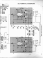
The voltage chart shown with the schematic diagram will
be of considerable aid in troubleshooting if there is a
vacuum tube voltmeter or similar test instrument available.
Voltages through the circuit should be compared carefully
with this chart. Deviations up to 20% are not signs 0
abnormality, but past this range they indicate a malfunc
tioning of the circuit at that point. Such measurements can
help to locate defective parts, miswiring, or bad tubes.
-