1
2
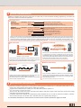
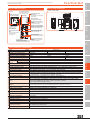
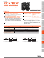
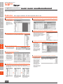
Diverse command methods
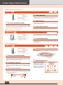
YAMAHA controllers allow the user to select from an ample array of control methods including programming, point trace and
pulse train to match the customer’s application.
Program entry
YAMAHA
SRC language
<examples> MOVA 1, 100
DO 1, 1
WAIT 2, 1
YAMAHA
<examples> IF DO(10)=1 THEN *END
BASIC language
MOVE P, P2, STOPON DI(1) =1
WAIT ARM
P3=WHERE
*END :
HOLD
Move to point No. 1 at 100% of speed.
Turn general purpose output No. 1 to ON.
Wait until general purpose input No. 2 turns ON.
Jump to *END if general purpose input No. 10 is ON. If not ON,
then proceed to next line.
Move to point No. 2. Stop if general purpose input No. 1 is ON during movement.
Wait until robot arm operation ends.
Write the current position in point No. 3.
Define the label with the “END” name.
Pause the program.
Single axis robot controllers use the YAMAHA SRC language Note which is simple yet contains all required functions such as I/O outputs and conditional
branching, etc. The multi axis controller RCX series uses the YAMAHA BASIC language capable of more sophisticated programs and includes all types of
arithmetic computations, flexible setting of variables and various conditional branching, etc. Both are easy to use robot language conforming to BASIC. These
match all manner of needs from simple beginning operations to sophisticated expert user tasks. Note. The 2-axis controller DRCX also uses YAMAHA SRC language.
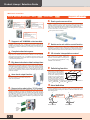
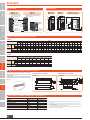
Specify point No.
I/O point trace
Remote command
Point data
DI 1 (20) ON
DI 2 (21) OFF
DI 3 (22) ON
P5
0000 0064 007 B 0109
CC-LINK DeviceNet
Controller
PLC
Start signal
PLC
PLC word function
Specified No.
Parallel I/O
Field bus CC-Link DeviceNet
Controller
The host device specified a point No. in binary and the robot moves to
that point No. when a start signal is input. The controller can operate
just by teaching the point data and does not need a program.
This uses CC Link or DeviceNet word functions to issue various data
or commands to the robot. It makes full use of word function
expandability ranging from simple operation instructions to writing of
point data and other sophisticated instructions and allows fully and
flexibly using robot controller functions from a host device.
Note. These functions are operable when selecting the option network board.
Online instructions
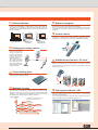
Pulse train
Pulse train
@MOVA1,100 c/r I/f
Positioning unit
Controller
A pulse train sent from the positioning unit controls the robot. The
controller does not have to handle programs or point data.
This control method is convenient when one wants to concentrate
control in a host or upstream device.
3
PC
Controller
A PC connected via RS232C or Ethernet Note can be used to issue
various commands and data directly to the robot controller or receive
data and status. All operations performed from a teaching pendant
can be executed from a PC.
Note. Ethernet is operable by selecting the option network board.
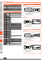
Multi-functions and expandability
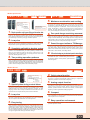
Multi-axis controllers support up to 10,000 points, and single-axis controllers up to 1,000 points (255 points on the TS
series). Up to 100 programs can be made on either type controller.
Supports various field networks including CC-Link, DeviceNet, Profibus, Ethernet Note.
Note. Some models do not support all networks.
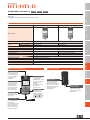
The TS series, RD series, SR1 series, and RCX series utilize a dual power supply system where the control power supply
and (main) power supply are separate.
Controllers support CE markings for EU (European) safety standards and so can also be used with confidence overseas.
The TS series (except for TS-S), SR1 series, and RCX series can support safety category 4.
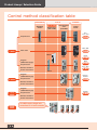
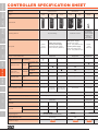
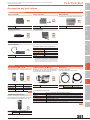
To view detailed information on each controller’s functions see the controller specification pages from P.349.
031