1
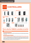
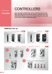
Compact
single-axis robots
APPLICATION TRANSERVO
1 to 2 axis
RCX221/RCX222
Robot controller with advanced functions
FLIP-X
Single-axis robots
A 2-axis robot controller with a full range of advanced functions
in a compact, space-saving size!
Very easy to use.
RCX221
RCX222
Main functions P.52
PHASER
Linear motor
single-axis robots
Features
1Compact
5 Anti-collision control function
Lightweight and compact design with main unit weight
of 2.8kg and height of 210mm.
XY-X
Cartesian
robots
2 Same price as predecessor “DRCX”
Delivers high-performance along with sophisticated
functions yet is the same price as the prior DRCX.
SCARA
robots
YK-X
3 The absolute position data
hold time: 1 year
YP-X
Pick & place
robots
The current position information is monitored even
during a long vacation, while the controller is kept
unused and while it is transported so that the return to
the origin process is not required when the controller is
activated again. (RCX222 / RCX222HP)
Internal function in controller acts to prevent carriage
collisions when using double carriages.
6 Applicable to various peripheral
equipments
Freely select I/O boards as needed.
Supports parallel I/O (NPN/PNP), CC-Link, DeviceNetTM,
PROFIBUS, and Ethernet.
7 Capable of using additional function
of “YC-Link” for additional axis
Linking the RCX series controller with the SR1 series
single-axis controller allows controlling a maximum of 8
axes (synchronous control of 6 axes).
CLEAN
4 Simultaneous control of PHASER
and FLIP-X
CONTROLLER INFORMATION
Offers mixed control of linear motor single-axis robot
PHASER series, along with 200 VAC motor single-axis
robot FLIP-X series. (RCX221/RCX221HP)
Model Overview
Name
Power
Operating method
Maximum number of controllable axes
Position detection method
Robot
positioner
Controllable robot
Pulse string
driver
Programming box
Support software for PC
RCX221 / RCX221HP
RCX222 / RCX222HP
Single phase: AC200V to 230V +/-10% maximum (50/60Hz)
Programming / Remote command / Operation using RS-232C communication
2 axes maximum
Incremental / Semi-absolute
Absolute / Incremental
Cartesian robot XY-X / Single-axis robot FLIP-X /
Cartesian robot XY-X / Single-axis robot FLIP-X /
Linear motor single-axis robot PHASER/
Pick & place robot YP-X
Pick & place robot YP-X
RPB / RPB-E (with enable switch) P.491
VIP+ P.489 / VIP
Robot
controller
Ordering method
RCX221 / RCX221HP
RCX222 / RCX222HP
iVY/
Electric
gripper
RCX221
Controller Note 1
RCX221
RCX221HP
RCX222
Usable for CE
No entry: Standard
E: CE marking
Regenerative unit Note 2
No entry: None
R: RG2
Option
Input/Output
Selection 1
N: NPN
P: PNP
CC: CC-Link
DN: DeviceNetTM
PB: PROFIBUS
EN: Ethernet
YC: YC-Link Note3
Input/Output Selection 2
No entry: None
N1: OP.DIO24/16 (NPN)
P1: OP.DIO24/16 (PNP)
EN: Ethernet Note4
Note 1. Driver selection and regenerative unit selection depends on the robot type.
See Specification selection table on following page.
Note 2. The regenerative unit (option) is required when operating a model designated by YAMAHA or a
load with a large inertia.
Note 3. Available only for the master.
Note 4. O nly when you have selected CC, DN or PB for Input/Output selection 1, you can select EN for
Input/Output selection 2.
474
Controller Note1
RCX222
RCX222HP
Usable for CE
No entry: Standard
E: CE marking
Regenerative unit Note2
No entry: None
R: RG2
Input/Output
Selection 1
N: NPN
P: PNP
CC: CC-Link
DN: DeviceNetTM
PB: PROFIBUS
EN: Ethernet
YC: YC-Link Note3
Input/Output Selection 2
No entry: None
N1: OP.DIO24/16 (NPN)
P1: OP.DIO24/17 (PNP)
EN: Ethernet Note4
Note 1. Driver selection and regenerative unit selection depends on the robot type.
See Specification selection table on following page.
Note 2. The regenerative unit (option) is required when operating a model designated by YAMAHA or a
load with a large inertia.
Note 3. Available only for the master.
Note 4. O nly when you have selected CC, DN or PB for Input/Output selection 1, you can select EN for
Input/Output selection 2.
Part names / dimensions
RCX221HP Dimensions
28
14
Single-axis robots
250
225
4
60
60
4
RCX222 Dimensions
RCX222HP Dimensions
14
48
28
14
5.5
Cartesian
robots
250
225
66
250
225
184.5
66
XY-X
60
Part names
4
60
4
SCARA
robots
44
YK-X
17
6.3
210
130
100
65.6
5.5
130
100
65.6
158
60
PHASER
44
Linear motor
single-axis robots
17
6.3
FLIP-X
210
130
100
5.5
5.5
250
225
184.5
(22)
158
130
100
14
Compact
single-axis robots
RCX221 Dimensions
APPLICATION TRANSERVO
RCX221/RCX222
Instruction manuals can be downloaded from our company website. Please use the following for more detailed information.
http://global.yamaha-motor.com/business/robot/
60
Regenerative unit RG2
30
RG2
Safety connector
TEMP
Parallel I/O network board
Ground
terminal
COM connector
SD memory connector
Note. Installs on the right side of the RCX221 (HP), RCX222 (HP).
Cannot be installed as a separate unit.
Note. Depth (D) is 158mm.
Installs on the right side of the RCX221 (HP), RCX222 (HP).
Cannot be installed as a separate unit.
Note. Photograph shows RCX222. The component names on the
RCX221 are the same but it does not come with an absolute
backup battery.
CONTROLLER INFORMATION
Weight
0.8kg
Regenerative
Approx. 420V or more
voltage
Regenerative stop
Approx. 380V or less
voltage
Cable for connection with
Accessory
controller (300mm)
210
Motor
connector
Dimensions
RGEN
CLEAN
Battery for
absolute data backup
RPB/RPB-E connector
KAS-M4130-00
(including cable supplied with unit)
W35 × H210 × D158mm
Model
Robot I/O connector
Connector for
regenerative
sensor
Specification selection table
The robot type automatically determines the normal specifications or HP specifications.
RCX221 / RCX221HP
RCX222 / RCX222HP
SXYxC
YP320X
HXYx
YP220BX
MXYx
SXYBx (ZFL20)
SXYBx (ZF)
SXYx (ZFL20)
SXYx (ZF)
HXYLx
HXYx
MXYx
NXY
SXYBx
SXYx
FXYBx
FXYx
N15D
2 axes
2 axes
RCX222
RCX222HP
Robot
controller
: Applicable
N18D
MF75D
MF50D
MF30D
MF20D
MF15D
MF7D
MR12D
Regenerative No entry (None)
unit
R (RG2)
YP-X Clean
XZ type
Regenerative No entry (None)
unit
R (RG2)
: Applicable
: Select per conditions
Required power supply capacity varies according to the robot type and number of axes. Prepare a
power supply using the following table as a general guide.
When connected to 2 axes (Cartesian robot or multi-axis robot) Motor capacity vs. current sensor table
20
20
Power capacity (VA)
500
700
900
1500
1700
2000
2400 (HP)
Connected motor
capacity
100W or less
200W
400W or more
Current sensor
05
10
20
Note. Motor output of the B14H is 200W but the current
sensor is 05.
Motor capacity exceeds a total of 450W.
Motor capacity for perpendicular axis
exceeds a total of 240W.
The following conditions apply when
perpendicular axis capacity is 240W or less.
• perpendicular axis is 200W.
• perpendicular axis is 100W and stroke is
700mm or more.
• there are 2 perpendicular axes at 100W,
and includes leads of 5mm.
B14H which maximum speed exceeds
1250mm per second.
Option
Axial current sensor value
X axis
Y axis
05
05
10
05
10
10
20
05
20
10
Conditions where regenerative
unit is needed on multi robots
iVY/
Electric
gripper
Power capacity
Pulse string
driver
RCX221
RCX221HP
XY-X
Arm type, Gantry type,
Moving arm type, Pole type
Robot
positioner
FLIP-X
PXYx
PHASER
Pick & place
robots
5
RG2
Item
(165)
YP-X
Front
Parallel I/O network board
Motor
connector
Basic specifications
Regenerative unit RG2
Status indicator
Regenerative unit
connector
Note. Even if axial current sensor values for each axis are interchanged no problem will occur.
475
APPLICATION TRANSERVO
RCX221/RCX222
XY-X
Cartesian
robots
Axis control
PHASER
Linear motor
single-axis robots
SCARA
robots
YK-X
Program
FLIP-X
Single-axis robots
YP-X
Pick & place
robots
CLEAN
Robot
positioner
General specifications Options
CONTROLLER INFORMATION
External input/output
Memory
Compact
single-axis robots
Basic specifications
Basic specifications
Pulse string
driver
Robot
controller
Item
Model
RCX221
RCX221HP
RCX222
RCX222HP
Number of controllable axes
2 axes maximum
Single-axis robot FLIP-X,
Single-axis robot FLIP-X, Cartesian robot XY-X,
Controllable robots
Linear motor single-axis robot PHASER,
Cartesian robot XY-X, Pick & place robot YP-X Pick & place robot YP-X
Connected motor capacity
2 axes total: 800W or less 2 axes total: 900W to 1200W 2 axes total: 800W or less 2 axes total: 900W to 1200W
Maximum power consumption
1700VA
2400VA
1700VA
2400VA
Dimensions
W130 × H210 × D158mm
Weight
Approx. 2.9kg
Approx. 3.1kg
Approx. 2.9kg
Approx. 3.1kg
Input power Control power supply Single phase AC200 to 230V +/-10% maximum (50/60Hz)
supply
Motor power
Single phase AC200 to 230V +/-10% maximum (50/60Hz)
Drive method
AC full-digital software servo
Position detection method
Resolver, Magnetic linear scale
Multi-turn resolver with data backup function
Operating method
PTP (Point to Point), Linear interpolation, Circular interpolation, Arch motion
Coordinate system
Joint coordinates, Cartesian coordinates
Position indication units
Pulses, mm (millimeters), deg (degrees)
Speed setting
1% to 100% (In units of 1%. However speed is in units of 0.01% during single-axis operation by DRIVE statement.)
1.Automatic
acceleration setting based on robot model type and end mass parameter
Acceleration setting
2.Setting based on acceleration and deceleration parameter (Setting by 1% unit)
Resolution
1μm
16384 P/rev
Origin search method
Incremental / Semi-absolute
Absolute / Incremental
Program language
YAMAHA BASIC (Conforming to JIS B8439 SLIM Language)
Multitasks
8 tasks maximum
Sequence program
1 program
Point-data input method
Manual data input (coordinate value input), Direct teaching, Teaching playback
Memory capacity
364KB (total capacity of program and points) (available program capacity during use of maximum number of points is 84KB)
Programs
100 program 9,999: maximum lines per program 98KB: maximum capacity per program
Points
10,000 points : maximum numbers of points
Memory Backup battery
Lithium metallic battery (service life 4 years at 0 to 40 )
Internal flash memory
512KB (ALL data only)
I/O input
Dedicated input 10 points, General input 16 points
STD.DIO
I/O output
Dedicated Output12 points, General output 8 points
SAFETY
Emergency stop input (Relay contact), Service mode input (NPN/PNP specification is set according to STD. DIO setting)
Brake output
Relay contact
Origin sensor input
Connectable to DC 24V normally-closed contact sensor
External communications
RS232C: 1CH D-SUB9 (female) RS422 : 1CH (RPB)
Slots
2 (inc.STD.DIO)
STD.DIO (NPN/PNP): Dedicated input 10 points / General input 16 points, Dedicated Output 12 points / General output 8 points
Optional input/output (NPN/PNP): General input 24 points / General output 16 points
CC-Link: Dedicated input 16 points, Dedicated Output 16 points, General input 96 points, General
Options
output 96 points (4 nodes occupied)
Type
DeviceNetTM: Dedicated input 16 points, Dedicated Output 16 points, General input 96 points, General output 96 points
PROFIBUS: Dedicated input 16 points, Dedicated Output16 points, General input 96 points, General output 96 points
Ethernet: IEEE802.3 10Mbps (10BASE-T)
Programming box
RPB, RPB-E (with enable switch)
Support software for PC
VIP+ / VIP
Operating temperature
0°C to 40°C
Storage temperature
-10°C to 65°C
Operating humidity
35% to 85%RH (non-condensing)
Absolute backup battery
–
Lithium metallic battery 3.6V 5400mAH (2700nAH × 2)
Absolute data backup period
–
1 year (in state with no power applied)
Noise immunity
IEC61000-4-4 Level3
Protecting structure
IP10
Installation conditions
•Install the RCX221/RCX222 inside the control panel.
iVY/
Electric
gripper
•Install the RCX221/RCX222 on a flat, level surface.
Option
•Install the RCX221/RCX222 in a well ventilated location,
with space on all sides of the RCX221/RCX222
(See fig. at right.).
•Do not block the heat-sink on the side panel.
RCX221
50mm or more
RCX221
XM
TEMP
ROB
I/O
50mm
or more
N
RPB
476
OP.2
N1
YM
: 35 to 85% RH (no condensation)
50mm
or more
ACIN
L
•Do not block the fan on the bottom of the controller.
•Ambient humidity
SRV
ERR
RDY
E-STOP
MOTOR
L1
•Ambient temperature : 0 to 40˚C
OP.1
RGEN
!
SAFETY
EXT.E-STOP
PIN11-12
17mm
or more
SD/COM
* Provide the same space
dimensions for RCX222.
Example of input signal connection
DC24V
DI
DI
DI
DI
GND
GND
PNP specification
DC24V
DC24V
DO
DO
FLIP-X
DC24V
NPN specification
Single-axis robots
PNP specification
Compact
single-axis robots
NPN specification
Example of output signal connection
APPLICATION TRANSERVO
RCX221/RCX222
Instruction manuals can be downloaded from our company website. Please use the following for more detailed information.
http://global.yamaha-motor.com/business/robot/
11
12
N
RPB
RPB connector
External service mode stop circuit
1 DI.COM
3 SERVICE
SAFETY
connector
DC24V
Internal
control
circuit
13
14
11
12
Main power supply
control circuit
Control signal
detection circuit
L
N
External emergency stopcircuit
Robot
positioner
Motor drive
circuit
External 24V
power supply
CONTROLLER INFORMATION
13
14
15
16
17
18
19
20
CLEAN
Connection when using the standard RPB with an external
emergency stop circuit (2)
Pick & place
robots
L
Motor drive
circuit
YP-X
Main power supply
control circuit
Control signal
detection circuit
Internal
control
circuit
Dedicated input common
Interlock signal
SERVICE mode input
Dedicated output common
Main power supply ready
Servo-on state output
No connection
RPB key switch contact
RPB key switch contact
EMG 24V, GND
Power supply for emergency stop input
Emergency stop ready signal
Emergency stop input 1
Emergency stop input 2
Emergency stop input 3
Emergency stop input 4
Enable switch input 1
Enable switch input 2
Enable switch input 3
Enable switch input 4
SCARA
robots
SAFETY DC24V
connector
DI.COM
INTERLOCK
SERVICE
DO.COM
MPRDY
SERVO OUT
NC
KEY1
KEY2
24VGND
EMG24V
EMGRDY
EMGIN1
EMGIN2
EMGIN3
EMGIN4
LCKIN1
LCKIN2
LCKIN3
LCKIN4
Name
YK-X
External emergency stopcircuit
13
14
I/O No.
Cartesian
robots
13 EMG1
14 EMG2
Terminal
number
1
2
3
4
5
6
7
8
9
10
11
12
13
14
15
16
17
18
19
20
XY-X
RPB connector
SAFETY connector signals
PHASER
Connection when using the standard RPB with an external
emergency stop circuit (1)
RPB
GND
Linear motor
single-axis robots
Emergency input signal connections
GND
Pulse string
driver
Robot
controller
iVY/
Electric
gripper
Option
477
APPLICATION TRANSERVO
RCX221/RCX222
Standard I/O [connector name: STD. DIO] signal table
Compact
single-axis robots
FLIP-X
Single-axis robots
PHASER
Linear motor
single-axis robots
XY-X
Cartesian
robots
SCARA
robots
YK-X
YP-X
Pick & place
robots
CLEAN
CONTROLLER INFORMATION
Robot
positioner
Pulse string
driver
Robot
controller
Terminal
number
1
2
3
4
5
6
7
8
9
10
11
12
13
14
15
16
17
18
19
20
21
22
23
24
25
26
27
28
29
30
31
32
33
34
35
36
37
38
39
40
41
42
43
44
45
46
47
48
49
50
Signal
name
DI01
DI10
DI03
CHK1
DI05
DI06
DI07
DI20
DI21
DI22
DI23
DI24
DI25
DI26
DI27
DO00
DO01
DO10
DO11
DO12
DO13
DO14
DO15
DO16
DO17
DI12
DI13
DI14
DI15
DI16
DI17
DI30
DI31
DI32
DI33
DI34
DI35
DI36
DI37
CHK2
DO02
DO03
DO20
DO21
DO22
DO23
DO24
DO25
DO26
DO27
Name
RCX221
RCX222
Servo ON
Sequence program control
Step run
Check input 1
I/O command run
Spare Note 1
Spare Note 1
General input 20
General input 21
General input 22
General input 23
General input 24
General input 25
General input 26
General input 27
EMG monitor (emergency stop monitor)
CPU OK
AUTO mode
Return-to-origin complete
Sequence program in progress
Auto operation in progress
Program reset output
Battery alarm output Note 2
END
BUSY
Auto operation start
AUTO mode switching
ABS reset (Not in use normally) Return-to-origin Note 3
Program reset
MANUAL mode
Return-to-origin (In use normally) ABS reset Note 4
General input 30
General input 31
General input 32
General input 33
General input 34
General input 35
General input 36
General input 37
Check input 2
Servo-on state
Alarm
General output 20
General output 21
General output 22
General output 23
General output 24
General output 25
General output 26
General output 27
Note 1. Use of DI06, DI07 is prohibited.
Note 2. DO15 is a memory backup battery voltage drop alarm output.
Note 3. Set origin return for axes using incremental specifications and axes using semi-absolute
specifications.
Note 4. Set origin return on axes using absolute specifications.
iVY/
Electric
gripper
Area check output can be assigned to DO20 to DO157.
(Area check output assignment differs depending on the controller software version. See the user’s manual
for details.)
Option
478
Option I/O [connector name: OP. DIO] signal table
Terminal Signal
number name
1
2
3
4
5
6
7
8
9
10
11
12
13
14
15
16
17
18
19
20
21
22
23
24
25
26
27
28
29
30
31
32
33
34
35
36
37
38
39
40
41
42
43
44
45
46
47
48
49
50
–
DI40
–
DI41
–
–
–
DI50
DI51
DI52
DI53
DI54
DI55
DI56
DI57
–
–
DO30
DO31
DO32
DO33
DO34
DO35
DO36
DO37
DI42
DI43
DI44
DI45
DI46
DI47
DI60
DI61
DI62
DI63
DI64
DI65
DI66
DI67
–
–
–
DO40
DO41
DO42
DO43
DO44
DO45
DO46
DO47
Name
Spare
General input
Spare
General input
Spare
Spare
Spare
General input
General input
General input
General input
General input
General input
General input
General input
Spare
Spare
General output
General output
General output
General output
General output
General output
General output
General output
General input
General input
General input
General input
General input
General input
General input
General input
General input
General input
General input
General input
General input
General input
Spare
Spare
Spare
General output
General output
General output
General output
General output
General output
General output
General output
Robot Language Table
WAIT
Function
Switches the hand of the main robot.
Defines the hand of the main robot.
Selects whether the main robot will be “right-handed”
or “left-handed” when moving to a point specified on a
Cartesian coordinate system.
Sets the shift coordinates for the main robot by using the
shift data specified by a shift variable.
Condition change
OUTPOS
PDEF
SPEED
TOLE
WEIGHT
SUSPEND
Function
Changes the acceleration coefficient parameter of the main group.
Changes the arch position parameter of the main group.
Changes the automatic movement speed of the main group.
Changes the axis tip weight parameter of the main group.
Changes the deceleration rate parameter of the main group.
Sets the axis sequence parameter to perform return-toorigin and absolute search in the main group.
Changes the OUT position parameter of the main group.
Defines the pallet used to execute a pallet movement command.
Changes the program speed for the main group.
Changes the tolerance parameter of the main group.
Changes the tip weight parameter of the main robot.
Language
ON ERROR
GOTO
RESUME
ERL
ERR
Function
If an error occurs during program execution, this command
allows the program to jump to the error processing routine
specified by the label without stopping the program, or
stops the program and displays the error message.
Resumes the program execution after recovery from an
error. This command is used in the error processing routine.
Gives the line number where an error occurred.
Gives the error code number when an error occurred.
PATH control
Language
PATH
PATH END
PATH SET
PATH START
Function
Sets the PATH motion on the main robot axis.
Terminates the path setting for PATH motion.
Starts the path setting for PATH motion.
Starts the PATH motion.
Torque control
Language
Function
Executes an absolute movement command on each axis
DRIVE
(with torque limit option) in the main group.
Changes the ma ximum torque instr uc tion for the
TORQUE
specified main group axis.
Sets the current limit time-out period on the specified
TRQTIME
main group axis when using a torque limit setting option
in the DRIVE statement.
Sets the current limit time-out period on the specified
TRQTIME
main group axis when using a torque limit setting option
in the DRIVE statement.
Option
ORGORD
START
iVY/
Electric
gripper
Language
ACCEL
ARCH
ASPEED
AXWGHT
DECEL
CUT
EXIT TASK
RESTART
Function
Changes the priority of the specified task.
Terminates a task currently being executed or temporarily
stopped.
Terminates its own task currently being executed.
Restarts a task that is temporarily stopped.
Sets the task number and priority of the specified task
and starts that task.
Temporarily stops another task being executed.
Robot
controller
SHIFT
Language
CHGPRI
Pulse string
driver
RIGHTY /
LEFTY
Task control
Robot
positioner
Function
Waits for the specified length of time (ms).
Outputs the specified value to the DO ports.
Outputs the specified value to the LO port to prohibit axis
movement or permit axis movement.
Outputs the specified value to the MO ports.
Turns ON the bits of the specified output ports and the
command statement ends.
Turns OFF the bits of the specified output ports.
Turns ON the bits of the specified output ports
Outputs the specified value to the SO port.
Outputs the specified value to the TO port.
1. Wai t s unt i l t h e c o n di t i o n i n D I / D O c o n di t i o n a l
expression are met.
2.Waits until positioning on the robot axes is complete
(within the tolerance range).
Coordinate control
Language
CHANGE
HAND
Function
Calls up sub-procedures defined by the SUB and END
SUB statements.
Terminates the sub-procedure defined by the SUB and
EXIT SUB
END SUB statements.
Does not permit variables declared with a program
written outside a subprocedure (SUB to END SUB) to be
SHARED
passed on as dummy arguments, but allows them to be
referred to with a sub-procedure.
SUB to END SUB Defines a sub-procedure.
CALL
CONTROLLER INFORMATION
RESET
SET
SO
TO
Language
CLEAN
OUT
Procedure
Pick & place
robots
LO
MO
Function
Assigns a value to the variable specified from the MPB/RPB.
Error control
I/O control
Language
DELAY
DO
Language
INPUT
YP-X
SERVO
Key control
SCARA
robots
ORIGIN
PMOVE
Function
Performs return-to-origin along robot absolute motor axes.
Performs an absolute movement of each axis in the main group.
Performs a relative movement of each axis in the main group.
Performs an absolute movement of the main robot axes.
Performs a relative movement of the main robot axes.
Performs return-to-origin on an incremental mode axis or
absolute search on a semi-absolute mode axis.
Performs a pallet movement of the main robot axes.
Controls the servo ON/OFF of the specified axes in the main group
or all axes (in main group and sub group).
Function
Displays the value of specified variable on the MPB/RPB screen.
YK-X
Language
ABSRST
DRIVE
DRIVEI
MOVE
MOVEI
Language
PRINT
Cartesian
robots
Robot operation
Screen control
XY-X
SELECT CASE
Allows control flow to branch according to conditions.
to END SELECT
Switches the currently executed program to a specified
SWI
program, and executes from the first line after compiling.
WHILE to WEND Controls repetitive operations.
Label statement Defines “labels” in program lines.
Function
Chang e s c o mmuni c at i o n m o de and init ialize t he
communication port.
Sends the read file data into a write file.
PHASER
REM
Language
ONLINE /
OFFLINE
SEND
Linear motor
single-axis robots
ON to GOTO
Communication control
FLIP-X
ON to GOSU
Function
Declares that a label or sub-procedure is in an external program.
Defines a function that is available to the user.
Declares the name of an array variable and the number of elements.
Terminates a FOR statement to NEXT statement loop.
Controls repetitive operations
Jumps to a subroutine with the label specified by a
GOSUB statement and executes the subroutine.
Unconditionally jumps to the line specified by a label.
Stops a program and resets it.
Pauses a program.
Allows control flow to branch according to conditions.
Executes a specified assignment statement.
Jumps to a subroutine with each label specified by a GOSUB
statement according to conditions and executes the subroutine.
Jumps to each line specified by a label according to conditions.
All characters that follow REM or an apostrophe (’) are
viewed as comments.
Single-axis robots
Language
DECLARE
DEF FN
DIM
EXIT FOR
FOR to NEXT
GOSUB to
RETURN
GOTO
HALT
HOLD
IF
LET
Compact
single-axis robots
General commands
APPLICATION TRANSERVO
RCX221/RCX222
Instruction manuals can be downloaded from our company website. Please use the following for more detailed information.
http://global.yamaha-motor.com/business/robot/
479
APPLICATION TRANSERVO
RCX221/RCX222
Accessories and part options
Compact
single-axis robots
Standard accessories
Power connector + wiring connection lever
Safety connector
RPB terminator (dummy connector)
Attach this to the RPB connector during operation
with the programming box RPB removed.
FLIP-X
Single-axis robots
PHASER
Linear motor
single-axis robots
Model
KAS-M5382-00
Model
KAS-M5370-00
Model
Note. Jointly used by SR1-P / SR1-X, RCX240.
KAS-M5163-30
Note. Jointly used by RCX240.
Standard I/O (STD.DIO) connector
Option I/O (OP.DIO) connector
L type stay (for installing front side, rear side.)
Use to install the controller.
XY-X
Cartesian
robots
Model
KAS-M533G-00
Model
KAS-M533G-10
Model
KAS-M410H-00
SCARA
robots
YK-X
Note. M odel No. is for a single bracket (L type stay). (Two are required
to install one controller.)
Battery case
Absolute battery (for RCX222 only)
Absolute battery basic specifications
Battery for absolute data back-up.
YP-X
Pick & place
robots
Item
Model
Battery type
Battery capacity
Data holding time
CLEAN
Dimensions
Weight Note2
Absolute battery
KAS-M53G0-11
Lithium metallic battery
3.6V/2,750mAh
About 1 year Note1
(in state with no power applied)
ϕ17 × L53mm
22g
CONTROLLER INFORMATION
Note1. When using 2 batteries. Note2. Weight of battery itself.
Note. Jointly used by SR1-X, RCX240.
Note. The absolute battery is subject to wear and requires replacement.
If trouble occurs with the memory then remaining battery life is
low so replace the absolute battery. The battery replacement
period depends on usage conditions. But generally you should
replace the battery after about 1 year counting the total time
after connecting to the controller and left without turning on the
power.
This is the absolute battery holder.
Model
KBG-M5395-00
Absolute battery installation conditions
1 to 2 batteries are required for each 2 axes.
1 battery…Data storage time of approximately
6 months (with no power applied)
2 batteries…Data storage time of
approximately 1 year (with no power applied)
Note. Absolute battery is not required for either of the 2 axes if
using incremental or semi-absolute specifications.
Options
Support software for PC VIP+
Programming box RPB / RPB-E
Robot
positioner
This device can perform all operations such as
manual robot operation, program entry and edit,
teaching and parameter settings.
Pulse string
driver
RPB
VIP+ is a simple to use application software that
makes tasks such as robot operation, writingediting programs, and point teaching easy to
visually understand.
RPB-E
Data cables
Communication cable for VIP+.
Select from USB cable or D-sub cable.
USB
Robot
controller
iVY/
Electric
gripper
RPB
RPB-E
Model
KBK-M5110-10 KBK-M5110-00
Enable
–
3-position
switch
CE marking Not supported
Applicable
P.491
VIP+ software model
Environment
OS
Option
CPU
Memory
Hard disk
Communication method
KX0-M4966-00
USB type (5m)
Model D-Sub type
9pin-9pin (5m)
D-Sub
KBG-M538F-00
KAS-M538F-10
Note. Data cable jointly used for POPCOM, POPCOM+, VIP, VIP+.
Note. USB driver for communication cable can also be downloaded from
our website (driver supports VIP+, POPCOM, POPCOM+, and
TS-Manager).
Microsoft Windows 2000 / XP / Vista (32bit / 64Bit) /
7 (32bit / 64Bit)
Processor that meets or exceeds the suggested requirements
for the OS being used.
Suggested amount of memory or more for the OS being used.
40MB of available space required on installation drive.
RS-232C, Ethernet
Note. For Ethernet communication, Ethernet unit for RCX series controller is required.
Applicable robot controllers RCX221 / RCX222 / RCX141 / RCX142 / RCX240 / RCX240S
Note. Microsoft and Windows are registered trademarks of Microsoft Corporation.
Note. A DOBE and ADOBE READER are registered trademarks of Adobe Systems Incorporated.
Note. Ethernet is a registered trademark of Xerox Corporation.
480
P.489
VIP+
RCX221 RCX222 RCX141 RCX142 RCX240 RCX240S
Compact
single-axis robots
Applicable controllers
APPLICATION TRANSERVO
Support software for PC
VIP+ is an easy to operate application software that makes tasks such as robot operation, writing-editing programs, and point teaching
easy to visually understand.
FLIP-X
Single-axis robots
Features
New support software VIP with improved ease of use
It is also possible to copy and paste the data from the other spread
sheet (chart calculation software).
XY-X
Cartesian
robots
The user interface
has been improved
with the VIP
Windows function
kept as it is so as to
achieve more ease
of use.
PHASER
6 Input the data in the work sheet form (Parameter, Point data)
Linear motor
single-axis robots
1 GUI updated for enhanced usability
Each of various functions
can be executed by simple
one click on the tool bar.
4 Expanded monitor function
9 List appointing (point where the system is restored)
iVY/
Electric
gripper
The data can be stored easily by using the drag & drop function.
Likewise, the stored data can be restored to the controller by operating
the mouse only.
Robot
controller
5 Data operation using the new drag & drop function
Pulse string
driver
Note. The label is stored in PC.
It is possible to create
the system restoration
point at any timing. By
doing so at important
points in the system
constructing process
when, for example,
something faulty is
found after the system
was changed, the
system can be returned
to the state before such
change easily.
Robot
positioner
The I/O conditions
and variables in the
controller can be
monitored at real time.
In the advanced mode,
it is also possible to
attach any label (Note)
to general purpose
input/output and others.
CONTROLLER INFORMATION
3 Fully equipped tool bar
CLEAN
The step being
performed during the
program execution
can be monitored.
Thus, it ispossible to
check which step is
performed without
stopping the program,
thereby debugging of
the program is made
much easier.
Pick & place
robots
8 Program execution monitor
YP-X
The data included in the controller is displayed legibly.
When reserved words (character
string reserved as the robot
language) are inputted, they are
colored automatically, making them
noted at one glance for easier
program editing.
SCARA
robots
2 Data displayed in the tree view form
YK-X
7 Syntax coloring when editing the program
Option
Select the data to be
stored.
Drag the selected data
to the document window
and drop it there.
Specify the file name
and this completes the
storage procedure.
489
APPLICATION TRANSERVO
VIP+
VIP PLUS function
Compact
single-axis robots
1 Easy to use
By connecting PC
and controller with
communication cable, robot
operation will be available
by the on-line command.
FLIP-X
Single-axis robots
With a number of robot
operation items provided
on one screen, any
operator can operate
easily without memorizing
the menu construction.
5 Robot operation
PHASER
Linear motor
single-axis robots
2 Programming editing
XY-X
Cartesian
robots
The program, point,
parameter, shift, and hand
can be edited on the PC
alone. Equipped with the
function selector having
the command searching
function which enables to
input the robot language
with ease.
6 On-line editing
Connecting a PC and the controller with a communication cable enable
to edit data from robot controllers just as with RPB / RPB-E.
SCARA
robots
YK-X
YP-X
Pick & place
robots
3 Data check function
CLEAN
Provided with the
equivalent data check
function to that of a robot
controller, it is possible to
correct data errors before
operation.
7 Creating point data There are three methods available for creating the point data.
CONTROLLER INFORMATION
MDI (Manual Data Input) teaching
The numeric keyboard is used to enter
position coordinate data directly.
4 Help function
Robot
positioner
When more information is
needed during operation,
press the [F1] or [HELP]
key, and the help screen will
appear.
Remote teaching
The robot arm is actually moved to
the target position using the keys for
point data registration.
Pulse string
driver
Direct teaching
Robot
controller
The robot arm is manually moved to the target position with the servo
motors off for point data registration.
iVY/
Electric
gripper
Environment / Ordering method
Option
490
P.491
Support software for PC VIP+
Environment
CPU
Communication method
KX0-M4966-00
Note. For Ethernet communication, Ethernet unit for RCX series controller is required.
Applicable robot controllers RCX221 / RCX222 / RCX141 / RCX142 / RCX240 / RCX240S
FLIP-X
Model
Single-axis robots
Memory
Hard disk
Microsoft Windows 2000 / XP / Vista (32bit / 64Bit) /
7 (32bit / 64Bit)
Processor that meets or exceeds the suggested requirements
for the OS being used.
Suggested amount of memory or more for the OS being used.
40MB of available space required on installation drive.
RS-232C, Ethernet
Compact
single-axis robots
OS
APPLICATION TRANSERVO
VIP+
Instruction manuals can be downloaded from our company website. Please use the following for more detailed information.
http://global.yamaha-motor.com/business/robot/
Controller and data cable connection diagrams
Communication cable for VIP+.
Select from USB cable or D-sub cable.
9 Pin
Converter
KAS-M538F-10
(D-Sub)
9 Pin
PC
Controller
SCARA
robots
YK-X
KBG-M538F-00
XY-X
USB type (5m)
Model D-Sub type
9pin-9pin (5m)
KBG-M538F-00
(USB)
9 Pin
D-Sub
USB connector
Cartesian
robots
RCX221/222
RCX40
RCX141/142
RCX240/240S
(9Pin)
USB
PHASER
Data cables (5m)
Linear motor
single-axis robots
Note. Microsoft and Windows are registered trademarks of Microsoft Corporation.
Note. A DOBE and ADOBE READER are registered trademarks of Adobe Systems Incorporated.
Note. Ethernet is a registered trademark of Xerox Corporation.
KAS-M538F-10
YP-X
Pick & place
robots
Note. Data cable jointly used for POPCOM, POPCOM+, VIP, VIP+.
Note. USB driver for communication cable can also be downloaded from
our website (driver supports VIP+, POPCOM, and TS-Manager).
Programming box
Applicable controllers
RCX221 RCX222 RCX240 RCX240S
CLEAN
RPB/RPB-E
Customers using the RCX141 / RCX142
controllers should use the connector
converter cable (See P.519.)
RPB / RPB-E basic specifications
Name
RPB
Part names and function
RPB-E
Display (screen)
External view
Dimensions
Weight
Cable length
RPB-E Rear side
3-position enable switch (only on RPB-E)
This switch is usable as part of an external (remote)
safety circuit.
Pressing this switch inwards or releasing it cuts off the
(RPB/robot) circuit. However that circuit is operable
when this switch is in middle position.
This enable switch is usually operable in service
mode. It functions as part of an external safety
circuit so that releasing the enable switch or
pressing it inwards set the robot to emergency stop.
Option
Enable switch
CE marking
Operating temperature
Operating humidity
RPB connector
This is a connector for
connecting the RPB to
the controller.
iVY/
Electric
gripper
Emergency stop button
RCX221 / RCX222 / RCX240 /
RCX240S
KBK-M5110-10
KBK-M5110-00
LCD (40characters 8 lines)
Normally closed contact point
(with lock function)
–
3-position
Not supported
Applicable
0°C to 40°C
35% to 85%RH (non-condensing)
W180 × H250 × D50mm (Strap holder,
emergency stop button not included.)
600g
5m (Standard), 12m (Options)
Robot
controller
Model
Display
Sheet keys
These are key switches
for operating the robot or
entering programs, etc.
These are broadly
grouped into 3 blocks
consisting of function
keys, control keys, and
data keys.
Pulse string
driver
Applicable controllers
Emergency stop button
Pressing this button during
robot operation sets the
robot to emergency stop.
These are B contact type
switches.
Robot
positioner
Liquid crystal display
(LCD) shows different
types of information with
8 lines × 40 characters.
Contrast is adjustable.
CONTROLLER INFORMATION
All operations can be performed from this device including manual robot operation, programming entry and editing, teaching and setting
parameters. The display works interactively with the operator so even an absolute beginner can easily learn how to use programming box.
491
APPLICATION TRANSERVO
Field network system with minimal wiring
NETWORK
Compact
single-axis robots
FLIP-X
Single-axis robots
As connection of the robot system and the
sequencer requires only one (4-wire) dedicated
cable, it is possible to save wiring of the entire
system, which contributes to efficient wiring work,
reduction of installation and maintenance costs,
etc.
Item
Applicable controllers
Version supporting CC-Link
Remote station type
Number of occupied stations
Station number setting
Communication speed setting
PHASER
Linear motor
single-axis robots
XY-X
Cartesian
robots
No. of CC-Link I/O Note1
Capable of simulating serial operation of parallel
I/O. With this function set properly, it is possible
to control various I/O units connected to the
parallel I/O of the robot controller, such as sensor
and relay from the sequencer side without using
the robot program, as if they are I/Os of the CCLink system.
Parallel external I/O Note2
DeviceNetTM
SCARA
robots
YK-X
YP-X
Pick & place
robots
As connection of the robot system and
the sequencer requires only one (5-wire)
dedicated cable, it is possible to reduce wiring
of the entire system, which contributes to
efficient wiring work, reduction of installation
and maintenance costs, etc.
CLEAN
Capable of simulating serial operation of
parallel I/O. With this function set properly, it is
possible to control various I/O units connected
to the parallel I/O of the robot controller, such
as sensor and relay from the sequencer side
without using the robot program, as if they are
I/Os of the DeviceNetTM system.
CONTROLLER INFORMATION
PROFIBUS
Option unit used to connect a YAMAHA robot
controllers RCX221 / RCX222 / RCX240 /
RCX240S to PROFIBUS.
Optimum for high speed data communication
and complicated communication processing.
Robot
positioner
Communication is made available among
devices of multiple number of manufacturers.
Pulse string
driver
Capable of simulating serial operation of
parallel I/O. With this function set properly, it is
possible to control various I/O units connected
to the parallel I/O of the robot controller, such
as sensor and relay from the sequencer side
without using the robot program, as if they are
I/Os of the PROFIBUS system.
Robot
controller
Basic specifications for network modules CC-Link
96 general use inputs/outputs, 16 dedicated
inputs/outputs (4 nodes occupied).
Option unit with networking functions that can
be incorporated in YAMAHA robot controllers,
RCX221 / RCX222 / RCX240 / RCX240S.
Ethernet
Shortest distance between
nodes Note3
Overall length
Network modules CC-Link
RCX221 / RCX222 / RCX240 / RCX240S
Ver. 1.10
Remote device node
Fixed to 4 stations
1 to 61 (set from the Rotary swich on board)
10Mbps, 5Mbps, 2.5Mbps, 625Kbps, 156Kbps (set from the Rotary
swich on board)
General input 96 points, General output 96 points,
Dedicated input 16 points, Dedicated output16 points
A function that simulates serial communication enables individual
control of the various points from a master sequencer, regardless of
the robot program.
0.2 m or more
100m/10Mbps, 150m/5Mbps, 200m/2.5Mbps, 600m/625Kbps,
1200m/156Kbps
RUN, ERR, SD, RD
Note3
Monitor LED
Note 1. Controller I/Os are updated every 10ms.
Note 2. With RCX 141/142, the exclusive input of the parallel I/O cannot be used other than the interlock input.With RCX221 / 222, the
exclusive input of the parallel I/O cannot be used. (The interlock input terminal is located on the SAFETY connector side.)
Note 3. These values apply when a cable that supports CC-Link Ver.1.10 is used.
Basic specifications for network modules DeviceNetTM
Item
Applicable controllers
Applicable DeviceNetTM specifications
Device Profile Name
Number of occupied CH Note1
MAC ID setting
Transmission speed setting
DeviceNetTM
I/O Note2
Normal
Compact
Parallel external I/O Note3
Network modules DeviceNetTM
RCX221 / RCX222 / RCX240 / RCX240S
Volume 1 Release2.0 / Volume 2 Release2.0
Generic Device (device number 0)
Normal: Input/output 24ch each, Compact: Input/output 2ch each
0 to 63
500Kbps, 250Kbps, 125Kbps (set using DIP switch on board)
General input 96 points, General output 96 points, Dedicated input 16
points, Dedicated output 16 points
General input 16 points, General output 16 points, Dedicated input 16
points, Dedicated output 16 points
The master module and up to four ports can be controlled regardless
of the robot program by using the pseudoserialization function.
100m/500Kbps, 250m/250Kbps, 500m/125Kbps
Overall length Note4
Branch length /
Overall branch length 6m max./39m max., 6m max./78m max., 6m max./156m max.
Monitor LED
MS (Module Status), NS (Network Status)
Network
length
Note1. Use the robot parameter to select Normal or Compact. However, with the controllers earlier than Ver.9.08 of RCX221 / 222, this
selection is not available and the setting remains the same as Normal.
Note2. Controller I/Os are updated every 10ms.
Note3. With RCX221 / 222, the exclusive input of the parallel I/O cannot be used. (The interlock input terminal is located on the SAFETY connector side.)
Note4. These values apply when a thick cable is used. The distance is less when a fine cable is used or when thick and fine cables are mixed in use.
Basic specifications for network modules PROFIBUS
Item
Applicable controllers
Communication profile
Number of occupied nodes
Setting of station address
Setting of communication
speed
PROFIBUS I/O Note1
Parallel external I/O Note2
Overall length
Monitor LED
Network modules PROFIBUS
RCX221 / RCX222 / RCX240 / RCX240S
PROFIBUS-DP slave
1 node
1 to 99 (set using Rotary switch on board)
9.6Kbps, 19.2Kbps, 93.75Kbps, 187.5Kbps, 500Kbps, 1.5Mbps,
3Mbps, 6Mbps, 12Mbps (automatic recognition)
General input 96 points, General output 96 points, Dedicated intput 16
points, Dedicated output 16 points
The master module and up to four ports can be controlled regardless
of the robot program by using the pseudoserialization function.
100m/3M·6M·12Mbps, 200m/1.5Mbps, 400m/500Kbps,
1000m/187.5Kbps, 1200m/9.6K·19.2K·93.75Kbps
RUN, ERR, SD, RD, DATA-EX
Note 1. The shortest I/O update interval of the controller is 10ms but the actual I/O update time varies depending on the update time
with the master station.
Note 2. With RCX221 / 222, the exclusive input of the parallel I/O cannot be used. (The interlock input terminal is located on the
SAFETY connector side.)
iVY/
Electric
gripper
Option
Option unit used to connect a YAMAHA robot controller
to Ethernet, which can be incorporated in YAMAHA robot
controllers, RCX221 / RCX222 / RCX240 / RCX240S.
Connection of this unit to the network operation by the TCP/
IP protocol with a 10BASE-T cable makes data exchange with
a robots easy.
Capable of making an easy access from the TELNET terminal
to the robot controller. As the command system is the same
as that by the RS-232C communication, even first-time users
can use it easily. (Windows PCs have a built-in TELNET
terminal called TELNET.EXE as a standard equipment.)
With a number of controllers connected in the network, it is
possible to perform integrated information control over robots
even at a distance from the work site.
492
RCX221 RCX222
RCX240 RCX240S
CC-Link
Option unit with networking functions that can
be incorporated in YAMAHA robot controllers,
RCX221 / RCX222 / RCX240 / RCX240S.
Applicable controllers
Basic specifications for network modules Ethernet
Item
Applicable controllers
Network specification
Connector specification
Baud rate
Communication mode
Network modules Ethernet
RCX221 / RCX222 / RCX240 / RCX240S
As specified for Ethernet (IEEE802.3)
RJ-45 connector (8-pole modular connector) 1 port
10Mbps (10BASE-T)
Half Duplex (Half-duplex)
Application layer: TELNET / Transport layer: TCP / IP
Network layer: IP, ICMP, ARP / Data link layer:
Network protocol
CSMA/CD /
Physical layer: 10BASE-T
Number of simultaneous log inputs 1
Setting of IP address, etc.
Set from RPB
Monitor LED
Run, Collision, Link, Transmit, Receive