1
Operation & Maintenance Data
OM 931-3
Group: WSHP
Part Number: 669479403
Date: May 2012
MicroTech® III Unit Controller for Water Source Heat Pump Units
©2012 McQuay International
•
800.432.1342
•
www.daikinmcquay.com
Contents
Introduction...........................................................................3
Replacing a MicroTech III circuit board:.............................6
Initial Power-Up....................................................................6
General Use and Information..............................................7
Occupied Operation...........................................................7
Thermostat Inputs (G, Y1, Y2, W1 and W2)......................7
Control Inputs (HP, LP, SLTS, COF, U, E, O).....................7
Control Outputs {A and IV/PR (H8)}..................................8
Fan Operation....................................................................8
Unoccupied Operation – Stand Alone
Thermostat Control............................................................8
Thermostat Inputs (G, Y1, Y2, W1, and W2).....................8
Control Inputs (HP, LP, SLTS, COF, U, E, O).....................9
Control Outputs {A and IV/PR (H8)}..................................9
Additional Operating Modes................................................9
High / Low Pressure Faults (HP/LP)................................10
Fan Operation during most Modes, Faults and
Shutdowns..........................................................................12
Troubleshooting the MicroTech III Unit Controller..........12
Troubleshooting the Water Source Heat Pump Unit.......14
Microtech® III Unit Controller Interface to External
Equipment...........................................................................15
Appendix A..........................................................................15
Operation and Maintenance of I/O Expansion Module....15
Introduction......................................................................15
Features..........................................................................15
Initial Power up...................................................................16
Operation.............................................................................17
Dual Circuit Units.............................................................17
Thermostat Inputs (Y2, W2)............................................17
Electric Heat Controls........................................................17
Boilerless Heat Coil Control.............................................17
Multiple Speed Fan Control...............................................17
Three-Speed Fan Operations..........................................17
Circuit Two, Additional Operating Modes........................17
Second Circuit Faults......................................................18
Appendix B .........................................................................19
MicroTech III Unit Controller with LonWorks®
Communication Module...................................................19
MicroTech III Controller with BACnet® Communication
Module.............................................................................20
Appendix C – Typical Wiring Diagrams............................21
MicroTech III Unit Controller (Standalone) –
208/230/460/575/60Hz/3-Phase......................................21
MicroTech III Unit Controller with Optional ECM
Motor, Desuperheater and I/O Expansion Module –
208/230/265/277/60 Hz/1-Phase.....................................22
MicroTech III Unit Controller with Optional ECM Motor,
Desuperheater, Electric Heat Coil and I/O Expansion
Module – 208/230/460/60 Hz/3-Phase............................23
MicroTech III Unit Controller with Optional ECM
Motor, Desuperheater, and I/O Expansion Module
208/230/460/60/3-Phase.................................................24
MicroTech III Unit Controller with PSC Motor,
Desuperheater and I/O Expansion Module for
Hot Gas Reheat Control (Unit Sizes 019-070)
208/230/60/1-Phase........................................................25
Controller Comparison.....................................................26
Introduction
This installation and operation manual covers the MicroTech® III unit controller for Daikin McQuay Water Source
Heat Pumps. For information on LonWorks® or BACnet®
communication modules and other ancillary components, see:
■ IM 927 - MicroTech III Water Source Heat Pump
LonWorks Communication Module.
■ IM 928 - MicroTech III Water Source Heat Pump Unit
Controller BACnet MS/TP Communication Module.
■ IM 933 - LonWorks Plug-In Software for use with
MicroTech III Unitary Controller - LonWorks
Communication Module.
■ IM 952 - Multiple Unit Control Panel (MUCP) for use
with MicroTech III Unit Controller and Mark IV Unit
Controller.
■ IM 955 - MicroTech III Water Source Heat Pump WallMounted Room Temperature Sensors.
■ IM 956 - Temperature Sensors for Units with MicroTech
III Unit Controller and LonWorks Communication
Module.
OM 931-3 / Page 3 of 28
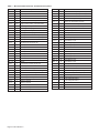
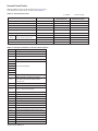
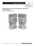
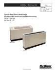
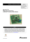
Table 1: MicroTech III Unit Controller Terminals & Descriptions
H1 - 1
24
24 VAC Power Input
H7 - 6
Red-Green-Yellow LED Common
H1 - 2
C
24 VAC Common
H8 - 1
1
Isolation Valve/Pump Request Relay N/O
H2 - 1
SL1
Fan Output - Switched L1
H8 - 2
Isolation Valve/Pump Request Relay N/C
H2 - 2
Blank Terminal
H8 - 3
24 VAC Common
H2 - 3
N
Fan Neutral
H9 - 1
Return Air Temperature Signal
H3 - 1
HP1-1
High Pressure Switch 1 Input Terminal 1
H9 - 2
Return Air Temperature Common
H3 -2
HP1-2
High Pressure Switch 1 Input Terminal 2
TB1 - 1
1
Room Sensor LED Output
H4 - 1
Discharge Air Temp Common
TB1 - 2
2
Fan Mode / Heat-Cool-Auto Input
H4 - 2
Discharge Air Temp Signal
TB1 - 3
3
Setpoint Adjust Input
H4 - 3
Leaving Water Temp Common
TB1 - 4
4
Room Temperature Sensor / Tenant Override
H4 - 4
Leaving Water Temp Signal
TB1 - 5
5
DC Signal Common
H5 - 1
1
I/O Expansion Board Common (Gnd)
Test-1
R
24 VAC
H5 - 2
I/O Expansion Board Common (Gnd)
Test-2
W2
Heat Stage 2 Input
H5 - 3
I/O Exp Board +5 VDC
Test-3
W1
Heat Stage 1 Input
H5 - 4
I/O Expansion Board SPI CE1
Test-4
Y2
Cool Stage 2 Input
H5 - 5
I/O Expansion Board SPI CLK
Test-5
Y1
Cool Stage 1 Input
H5 - 6
I/O Expansion Board SPI OUT
Test-6
G
Fan
H5 - 7
I/O Expansion Board SPI IN
TB2 - 1
R
24 VAC
H5 - 8
I/O Expansion Board +12 VDC
TB2 - 2
A
Alarm Output
H5 - 9
I/O Expansion Board 24 VAC
TB2 - 3
W2
Heat Stage 2 Input
H5 - 10
I/O Expansion Board 24 VAC
TB2 - 4
W1
Heat Stage 1 Input
H5 - 11
Spare
TB2 - 5
Y2
Cool Stage 2 Input
H5 - 12
Spare
TB2 - 6
Y1
Cool Stage 1 Input
H6 - 1
Condensate Overflow Signal Input
TB2 - 7
G
Fan Input
H6 - 2
Low Temp 1 Sensor Common
TB2 - 8
O
Tenant Override Input
H6 - 3
Low Temp 1 Sensor Signal
TB2 - 9
C
24 VAC Common
H6 - 4
Low Pressure Switch 1 Source Voltage
TB3 - 1
E
Mark IV Emergency Shutdown Input
H6 - 5
Low Pressure Switch 1 Signal
TB3 - 2
U
Mark IV Unoccupied/Occupied Input
H6 - 6
Reversing Valve 1 Common
L1 - 1
L1 - 1
Line Voltage Terminal 1
H6 - 7
Reversing Valve 1 Output
L1 - 2
L1 - 2
Line Voltage Terminal 2
H7 - 1
1
Dummy Terminal
L1 - 3
L1 - 3
Line Voltage Terminal 3
H7 - 2
Dummy Terminal
N1
N1
Neutral Terminal 1
H7 - 3
Red LED Output
N2
N2
Neutral Terminal 2
H7 - 4
Green LED Output
N3
N3
Neutral Terminal 3
H7 - 5
Yellow LED Output
1
Page 4 of 28 / OM 931-3
1
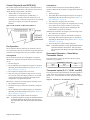
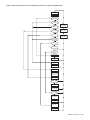
Figure 1: MicroTech III Unit Controller Terminal Locations
OM 931-3 / Page 5 of 28
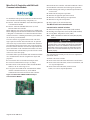
CAUTION
The MicroTech III circuit board incorporates static sensitive devices. A static charge from touching the device can damage the
electronic components. To help prevent damage during service,
use static discharge wrist straps.Static discharge wrist straps
are grounded to the heat pump chassis through a 1 Mohm resistor.
Initial Power-Up
Pre start check list:
A random start delay time between 180 and 240 seconds is
generated at power up.
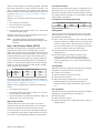
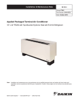
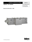
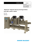
Figure 2: Location of Configuration Jumpers on the Base
Board Controller
Replacing a MicroTech III circuit
board:
1. Connect wrist strap to unit.
2. Remove faulty board and place on static protected surface.
3. Remove replacement board from static protected bag.
Do not touch circuit board; hold by edges.
4. Holding board in grounded hand, install board in unit.
5. Insert faulty board in empty static bag for return.
Table 2: Configuration Jumper Settings
Jumper
Description
Options
Open for normal operation mode
JP1
Mode
Shorted for service/test operation mode
JP2 Fan operation only applies to Open for continuous fan operation
network controls
Shorted for cycling fan operation
Open for water freeze protection
JP3
Freeze protection
Shorted for antifreeze protection
JP4
Future spare
Future spare
JP5
Set point adjustment range only
Open for adjustment range of -3.0° to +3.0° F
applies to network controls with a Shorted for 50° to 90° F adjustment range
room temperature sensor
Open for thermostatic room control
JP6
Room control type
Shorted for room temperature sensor control, MicroTech III only
JP7
Future spare
Future spare
JP8
Future spare
Future spare
Page 6 of 28 / OM 931-3
General Use and Information
The MicroTech III unit controller is provided with two drive
terminals, R (24VAC), and C (0VAC) that can be used to
drive the thermostat inputs (G, Y1, Y2, W1, and W2) and
control inputs (U, E and O). Any combination of or single
board drive terminal (R, or C) may be used to operate the MicroTech III’s unit controller or thermostat inputs. Some of the
control inputs are used within the Water Source Heat Pump
and not accessible to the end user without a field service tool
(laptop with appropriate software).
Typically the MicroTech III unit controller's R (24VAC)
terminal is used to drive the board’s thermostat inputs and
control inputs by connecting it to the R terminal of an industry standard thermostat. The control outputs of the standard
thermostat are then connected to the MicroTech III unit
controller's thermostat inputs and control inputs as needed.
Any remaining board input(s) may be operated by additional
thermostat outputs or remote relays (dry contacts only).
All MicroTech III unit controller inputs must be operated by
dry contacts powered by the control board’s power terminals.
No solid state devices (Triacs) may be used to operate MicroTech III unit controller inputs. No outside power sources may
be used to operate MicroTech III. All units must be properly
grounded per local code requirements. See the Installation
and Maintenance bulletin specific to your Water Source Heat
Pump.
Occupied Operation
Board LED Status – Occupied
YellowGreen Red
Off
On
Off
The board will be in occupied mode if the unoccupied
terminal (U) is de-energized.
Thermostat Inputs (G, Y1, Y2, W1 and W2)
Thermostat inputs used during occupied operation are G, Y1,
and W1, which when energized will activate the Fan Only,
Cooling Mode, and Heating Mode respectively. Input W2
and Y2 work the same as W1 and Y2 respectively for single
circuit units in occupied mode. For information on W2 and
Y2 for dual circuit units, refer to "Dual Circuit Units" on page
17.
The MicroTech III unit controller is configured so that when
either the Y1 or W1 input is energized the unit fan is also
activated with Cooling or Heating Modes. In other words,
energizing Y1 and G together will have the same effect as energizing just Y1. The W1 input has priority over the Y1 input.
In situations when both inputs W1 and Y1 become energized
(unlikely) in any order the unit will go into the Heating Mode
as described below:
1. If the unit is in Cooling Mode, Y1 is energized. If W1
becomes energized and remains energized, the following
will occur:
• The compressor de-energizes.
• The compressor restarts at 180 seconds (powerup
delay timer).
• The reversing valve output energizes within 5 to 20
seconds of the compressor being energized (Heating
Mode position), depending on the configuration of
jumpers JP7 and JP8.
2. If the unit is in Cooling Mode, Y1 is energized. If W1
becomes energized momentarily, the controller deenergizes the compressor for 180 seconds (shortcycle
timer) and then returns to the cooling mode.
3. However, if the unit is in Heating Mode, W1 is energized.
If Y1 becomes energized the unit remains in Heating
Mode.
4. Y2 is the second stage cooling, and applies to dual
compressor units.
Control Inputs (HP, LP, SLTS, COF, U, E, O)
The control inputs are High Pressure (HP), Low Pressure
(LP), Suction Line Temperature Sensor (SLTS), Condensate
Overflow (COF), Unoccupied (U), and Remote Shutdown
(E). The control inputs are in normal states during occupied
mode. The state of each control in occupied mode during
normal operation is as follows:
• High / Low Pressure (HP, LP): energizes, switch is closed
(no fault).
• Suction Line Temperature Sensor (SLTS): temperature
sensor on the suction line which provides low temperature
protection. Condensate Overflow(COF):sensing no
condensate water (no fault).
• Unoccupied (U): de-energized (no signal).
• Remote Shutdown (E): de-energized (no signal).
• Tenant Override (O): has no effect in occupied mode.
OM 931-3 / Page 7 of 28
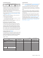
Control Outputs {A and IV/PR (H8)}
The control outputs are Alarm Fault (A) and Isolation Valve
/ Pump Request {IV/PR (H8)}. The operation of the control
outputs during occupied mode is as follows:
• Alarm Fault (A): energized (no fault).
• Isolation Valve / Pump Request {IV/PR (H8)}: is
selectable to be energized when the compressor is off
(normally closed), or when the compressor is on (normally
open), by moving the wire lead to the appropriate
terminal.
Figure 3: H8 Terminals on MicroTech III Board
Fan Operation
The G terminal controls continuous fan operation. The fan
runs continuously when the G terminal is energized. When the
G terminal is de-energized, the fan cycles with the compressor.
Cooling Mode
The Y1 terminal controls the Cooling Mode of operation.
When the Y1 terminal is energized (24VAC), the following
occurs:
1. The fan energizes.
2. The IV/PR (H8) control output de-energizes or energizes
depending on the H8 terminal wiring (refer to Table 1 on
page 4 & Figure 1 on page 5).
3. The compressor energizes after 30 seconds.
4. If the reversing valve output is energized, the reversing
valve out put will be de-energize within 5 to 20 seconds
of the compressor being energized, depending on the
configuration of jumpers JP7 and JP8.
When the Y1 terminal is de-energized, the following occurs:
1. The compressor de-energizes.
2. The fan de-energizes, unless the G terminal is energized
(24VAC).
3. The IV/PR (H8) control output energizes or deenergizes
depending on the H8 terminal wiring (refer to Table 1 on
page 4 & Figure 1 on page 5).
4. The reversing valve output remains de-energized.
Note: To prevent compressor cycling, the required minimum
on/off time default is 180 seconds. This may cause
the compressor time delay to be longer than indicated
above.
Page 8 of 28 / OM 931-3
Heating Mode
The W1 terminal controls the occupied Heating Mode of
operation. When the W1 terminal is energized, the following
occurs:
1. The fan energizes
2. The IV/PR (H8) control output de-energizes or energizes
depending on the H8 terminal wiring (refer to Table 1 on
page 4 & Figure 1 on page 5).
3. The compressor energizes after 30 seconds.
4. If the reversing valve output is de-energized, the reversing
valve output will be energize within 5 to 20 seconds
of the compressor being energized, depending on the
configuration of jumpers JP7 and JP8.
When the W1 terminal is de-energized, the following occurs:
1. The compressor de-energizes.
2.The fan de-energizes, unless the G terminal is energized.
3. The IV/PR (H8) control output energizes or deenergizes
depending on H8 terminal wiring (refer to Table 1 on page
4 & Figure 1 on page 5).
4. The reversing valve output remains energized.
Note: To prevent compressor cycling, the required minimum
on/off time default is 180 seconds. This may cause
the compressor time delay to be longer than indicated
above.
Unoccupied Operation – Stand Alone
Thermostat Control
The board will be in unoccupied mode if the unoccupied
terminal (U) is grounded.
Board LED Status – Unoccupied
YellowGreen Red
Off
On
On
Thermostat Inputs (G, Y1, Y2, W1, and W2)
The only thermostat input used during unoccupied operation
is W2, which when energized will activate Heating Mode.
Inputs G, Y1, Y2 and W1 have no effect during unoccupied
mode.
Figure 4: Terminal "U" - Grounded for Unoccupied
Control Inputs (HP, LP, SLTS, COF, U, E, O)
The control inputs are High Pressure (HP), Low Pressure
(LP), Suction Line Temperature Sensor (SLTS), Condensate
Overflow (COF), Unoccupied (U), and Remote Shutdown
(E). The state of each control input during unoccupied mode
during normal operation is as follows:
■ High / Low Pressure (HP, LP): energizes, switch is closed
(no fault).
■ Suction Line Temperature Sensor (SLTS): greater than
setpoint unit operates (no fault).
■ Condensate Overflow (COF): sensing no condensate
water (no fault).
■ Unoccupied (U): energizes (signal provided).
■ Remote Shutdown (E): de-energizes (no signal).
■ Tenant Override (O): see "Tenant Override" on page 11.
Control Outputs {A and IV/PR (H8)}
The control outputs provided by the MicroTech III unit
controller are Alarm Fault (A) and Isolation Valve / Pump
Request (IV/PR (H8)). The operation of the control outputs
during unoccupied mode is the same as in occupied mode
(see "Occupied Operation" on page 7).
Fan Operation
The G terminal has no effect during unoccupied mode.
Cooling Mode
Cooling operation is not available during unoccupied mode.
Heating Mode
The W2 terminal controls the unoccupied Heating Mode of
operation. When the W2 terminal is energized the following
occurs:
1. The fan energizes.
2. The IV/PR (H8) control output energizes or deenergizes
depending on H8 terminal wiring (refer to Table 1 on page
4 & Figure 1, page 5).
3. The compressor will start 30 seconds later.
4. If the reversing valve output is de-energized, the reversing
valve output will energize within 5 to 20 seconds of
the compressor being energized, depending on the
configuration of jumpers JP7 and JP8.
When the W2 terminal is de-energized the following occurs:
1. The compressor de-energizes.
2. The IV/PR (H8) control output energizes or deenergizes
depending on H8 terminal wiring (refer to Table 1 on page
4 & Figure 1, page 5).
3. The reversing valve remains energized.
Note:
Additional Operating Modes
Brownout
Board LED Status – Brownout
YellowGreen Red
Off
Flash
Off
Brownout condition is provided to protect the water source
heat pump’s motor electrical damage due to low voltage
conditions.
The MicroTech III unit controller is designed to monitor the
24VAC power supply to the board. If the line voltage supplied
to the water source heat pump drops, the 24VAC supply to the
control board will also drop. When the line voltage supplied
to the unit drops below approximately 80% of the unit nameplate rated value, the controller goes into brownout condition.
The controller remains in brownout condition until line voltage returns to approximately 90% of the unit nameplate value.
When in brownout condition, thermostat and control inputs
have no affect upon unit operation. No faults or modes have
higher priority than a brownout fault condition. Remote
shutdown and brownout conditions have the same level of
priority. See "Priority of Faults and Modes" on page 12 and
Table 3 on page 12.
When the unit is in brownout condition the following occurs:
1. The compressor de-energizes.
2. The reversing valve de-energizes.
3. The fan de-energizes.
4. Fault terminal (A) de-energizes (fault). A to C will be used
to indicate an alarm signal.
When the line voltage supplied to the unit returns to acceptable levels (~90% of nameplate) the controller returns to the
current mode.
Remote Shutdown
Board LED Status – Remote Shutdown
YellowGreen Red
Off
Off
Flash
When the E terminal is grounded, the MicroTech III unit
controller enters remote shutdown mode. Remote shutdown
is provided so that when properly connected to a building
automation system, remote switch, etc., the E terminal can be
used to shut down the water source heat pump.
Figure 5: Terminal "E" - Grounded for Remote Shutdown
To prevent compressor cycling, the required minimum on/off time default is 180 seconds. This may cause the compressor time delay to be longer than indicated above.
OM 931-3 / Page 9 of 28
When in remote shutdown (E terminal grounded), thermostat
and control inputs have no affect upon unit operation. No
faults or modes have higher priority than remote shutdown.
Remote shutdown and brownout condition have the same level
of priority. See "Priority of Faults and Modes" on page 12
and Table 3 on page 12.
When the unit is in remote shutdown mode, the following
occurs:
1. The compressor de-energizes.
2. The reversing valve de-energizes.
3. The fan de-energizes.
4. Fault terminal (A) de-energizes (fault). A to C will be used
to indicate an alarm signal.
When the E terminal is no longer grounded the unit will automatically return to normal operation.
Note: The remote shutdown input (E) will suspend unit
operation. Disconnect power when servicing the unit/
controller.
High / Low Pressure Faults (HP/LP)
Normally closed high and low refrigerant pressure switches
help protect the water source heat pump from excessively
high or low refrigerant pressures. The MicroTech III unit controller monitors these switches individually. If the compressor
is running and the HP circuit is open, the controller enters a
pressure fault mode. If the compressor is running and the LP
circuit is open after a time delay (default of 30 seconds, adjustable if a communication module is present) the controller
enters a low pressure fault mode. The fan operates normally
during a pressure fault condition.
HP LP
Board LED Status – High/Low Pressure Faults
YellowGreen Red
Flash
Off
Off
Solid
Off
Off
Only brownout and remote shutdown modes have higher priority than the pressure fault mode. See "Priority of Faults and
Modes" on page 12 and Table 3 on page 12.
When the unit is in high pressure fault mode the following
occurs:
1. The compressor de-energizes.
2. The fault terminal (A) de-energizes (fault). A to C will be
used to indicate an alarm signal.
3. After the shutdown is complete the IV/PR(H8) output will
change state. (On to Off / Off to On).
High Pressure Reset
After the HP circuit is closed, the unit does not return to
normal operation until the control board is reset. The unit is
locked out in this manner until the unit can be serviced.
The control board is reset by a short interruption of unit power, by holding down the tenant override button for more than
10 seconds, or via the Building Automation System (BAS).
Page 10 of 28 / OM 931-3
Low Pressure Reset
The low pressure switch fault is subject to intelligent reset. If
the pressure recovers, it resets three times within a 24-hour
time period. If further faults are detected within the 24 hours,
the controller must be manually reset as described in the High
Pressure Reset section above.
Low Suction Line Temperature Fault
Board LED Status – Low Suction Line Temperature Fault
YellowGreen Red
Off
Off
Flash
Heating Mode
When the suction line temperature falls below 28°F on standard equipment (6.5°F on Geothermal) the low temperature
fault generates the following:
■ The reversing valve de-energizes. The compressor and fan
continue to operate in cooling mode for 60 seconds, which
results in a defrost mode. This defrosts any ice that may
have accumulated in the water-to-refrigerant coil, because
of a lack of condenser water flow in heat mode.
■ In heat mode the low temperature fault is subject to
Intelligent Reset.
■ The fault terminal A de-energizes while the unit is
in defrost mode. It will stay de-energized until the
temperature recovers to 38°F for standard equipment
(18°F for geothermal). A to C will be used to indicate an
alarm signal.
Cooling Mode
When the suction line temperature falls below 28°F standard
equipment (6.5°F geothermal) in cool mode the:
■ Compressor de-energizes.
■ The fan continues to run for 60 seconds.
■ Alarm output de-energizes.
■ When the suction line temperature recovers to 38°F
standard equipment (18°F on geothermal) the low
temperature fault continues and the unit will be locked
out.
Fan Only Mode
When the suction line temperature falls below 28°F standard
equipment (6.5°F geothermal) in cool mode the:
■ Fan de-energizes.
■ Alarm output de-energizes.
■ In Fan Only mode, the low temperature fault is subject to
Intelligent Reset.
Condensate Overflow
Tenant Override
Board LED Status – Condensate Overflow
YellowGreen Red
Off
Off
On
Note: It is recommended that the "Occupied Operation" and
"Unoccupied Operation – Stand Alone Thermostat
Control" sections be reviewed prior to this section.
The MicroTech III unit controller's condensate sensor is
designed to detect excessively high condensate water levels
in the drain pan. When high condensate water levels are
detected during cooling mode, the controller enters into
condensate fault mode. The fan operates normally during the
condensate overflow fault mode.
Some faults and modes have higher priority than condensate
overflow mode. See "Priority of Faults and Modes" on page
12 and Table 3 on page 12.
When the unit senses a condensate overflow fault while in
cooling mode the following occurs:
1. The compressor de-energizes.
2. The fault terminal (A) de-energizes (fault). A to C will be
used to indicate an alarm signal.
When condensate levels return to normal, the controller will
automatically return to normal operation.
The MicroTech III unit controller enters tenant override
mode when the O terminal is energized for 3 seconds during
a period when the Water Source Heat Pump is in unoccupied
mode.
Tenant override allows a tenant, returning to the controlled
space after the unit has been placed in unoccupied mode, to
activate the tenant override input (O) and place the unit into
occupied mode.
Any remote button or switch with momentary dry contacts
can be used for this purpose. During the 2-hour tenant override period the W2 input will be ignored and the G, Y1, and
W1 inputs will be used (see "Occupied Operation" on page
7) for unit operation. If the U terminal is still grounded
after the 2-hour time limit, the unit will return to unoccupied
mode. Refer to "Unoccupied Operation – Stand Alone Thermostat Control" on page 8.
Remote Reset of Automatic Lockouts
The Remote Reset feature provides the means to remotely
reset some lockouts generated by high-pressure and/or lowtemperature faults. When the MicroTech III unit controller
is locked out due to one of these faults, and the cause of the
fault condition has been cleared, energizing the O-terminal
for 10 seconds or more forces the MicroTech III unit controller to clear the lockout. Cycling unit power also clears a lockout if the conditions causing the fault have been alleviated.
Intelligent Reset (See Table 2)
The Intelligent Reset feature helps to minimize nuisance trips
of automatic lockouts caused by low-temperature faults. This
feature clears faults the first two times they occur within a
24-hour period and triggers an automatic lockout on the 3rd
fault. The retry count is reset to zero every 24 hours.
Table 2: Faults
● = Applies
Fault
Auto Recovery
Invalid Configuration Jumper Setting
–
Brownout
– = Does not apply
Remote Reset (Tenant Override)
–
Reset (Network
Command or Power)
●
●
– ●
HP1
●
●
●
LP1
●*
●
●
LT1 (In Heating)
●*
●
●
LT1 (In Cooling)
–
●
●
–
–
●
–
–
●
Condensate Overflow ●
–
●
EEPROM Failure
–
–
–
Sensor
Failure
Room Temperature, LT1, LT2, EWT(w/Boilerless EH Only)
* Auto Recover for the first two occurrences, lockout on the third occurrence within 24 hours, i.e., subject to “Intelligent Reset.”
OM 931-3 / Page 11 of 28
Fan Operation during most Modes,
Faults and Shutdowns
The MicroTech III unit controller allows fan operation during
most modes, faults and shutdowns to facilitate maximum
space comfort and control. However, the fan does not operate
during brownout condition. During most modes, faults, or
shutdowns the fan will operate under the following conditions:
1. In occupied modes, the thermostat inputs G, Y1, or W1
are energized.
2. In unoccupied modes, the thermostat input W2 is
energized.
Operation with the High Speed Jumper
■ The MicroTech III unit controller includes a high-speed
jumper terminal labeled JP1 to speed system check out
and trouble-shooting. See Figure 2 on page 6 for JP1
location.
Note: This jumper is intended for Daikin McQuay factory unit
testing and should only be used by trained service
technicians as several timing functions are reduced to
speed system check out.
■ Disconnect power to the unit when installing or removing
the high-speed jumper.
■ The high speed jumper should only be used for a short
period of time for testing of the unit’s operation by a
trained service technician. The jumper must be removed
for normal unit operation.
■ If the jumper is left on after system check out, the unit
may be damaged.
Priority of Faults and Modes
The MicroTech III unit controller is configured with mode
and fault priorities. Table 3 illustrates that the lower the priority level number, the higher the priority of the fault or mode.
There are some exceptions to this priority list. For example,
tenant override has no affect on occupied modes.
Table 3: Priority Level of Faults and Modes
Priority Level
1
Mode or Fault
Emergency Shutdown Mode
2
Brownout
3
High Pressure
4
Low Pressure
5
Low Temperature
6
Tenant Override Mode
7
Unoccupied Heating Mode
8
Occupied Heating Mode
9
Condensate Overflow
10
Occupied Cooling Mode
Page 12 of 28 / OM 931-3
Table 4: MicroTech III Unit Controller Status LED's
Status LED’s Thermostat Alarm Light
Mode / Fault
Yellow Green Red
Output-Terminal “A”
Occupied, Bypass,
Standby, or Tenant Off
On
Off
Energized
Override
Unoccupied
On
On
Off
Energized
Condensate Overflow
On
Off
Off
De-energized
High Pressure 1 Fault
Off
Off Flash
De-energized
Low Pressure 1 Fault
Off
Off
On
De-energized
Low Temperature 1 Fault Flash
Off
Off
De-energized
Brownout Off
Flash Off
De-energized
Emergency Shutdown
Off
Flash Off
De-energized
Room/Return Air or Low
Flash Flash On
De-energized
Temp Sensor 1 Failure
Service Test Mode Enabled 1
On
On
Off
De-energized
Serial EEPROM
Corrupted
On
On
On
De-energized
Network “Offline”
Received
Off
Off
Off
De-energized
1Compressor
relay/compressor terminal is labeled COMP, switched line of
the same electric input as any of the L1 terminals.
Troubleshooting the MicroTech III
Unit Controller
DANGER
To avoid electrical shock, personal injury or death, be sure
that field wiring complies with local and national fire, safety,
and electrical codes, and voltage to the system is within the
limits shown in the job-specific drawings and unit electrical
data plate(s).
Power supply to unit must be disconnected when making
field connections. To avoid electrical shock, personal injury or
death, be sure to rigorously adhere to field wiring procedures
regarding proper lockout and tagout of components.
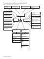
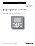
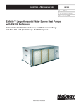
Figure 6: MicroTech III Unit Controller LED Status and Faults Troubleshooting Reference
Read Outputs
Check Timers
Yes
Brownout
No
Yes
High
Pressure
Yes
Low
Pressure
No
Start
Compressor
No
Yes
Yes
Yes
Yes
30 Second
Time Delay
Low Suct
Temp Sensor
No
Low Suct
Temp
Request for
Water Flow
No
Room Temp
Sensor Failure
No
R-W1
No
Yes
R -Y 1
No
Condensate
Overflow
Stop Compressor
Flash Green LED
Stop Compressor
Flash Red LED
Stop Compressor
Flash Yellow LED
Flash Green LED
Solid Red LED
Stop Compressor
Heating Mode
No
Yes
Flash Yellow LED
Run in Cooling
Mode for 1 Min.
Cooling Mode
No
Yes
Turn on
Yellow LED
Stop Compressor
Reversing
Valve On
Time Delay
OM 931-3 / Page 13 of 28
Troubleshooting the Water Source Heat Pump Unit
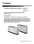
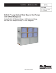
Figure 7: Troubleshooting Guide - Unit Operation
Low voltage, check
power supply voltage
Fuse may be blown,
circuit breaker is open
Wire may be loose or broken.
Replace or tighten wires
Check wiring - loose or
broken and check for faulty
connection
Check relays and contacts,
also capacitor and wiring
Check high pressure switch,
low pressure switch and low
temperature switch to see if
unit is cycling on the safety
Check capacitor
Neither fan, nor compressor
runs and all LED lights
are off
Compressor runs
in short cycle
Unit
Fan operates,
compressor does not
Check wiring - loose or broken
and check for bad connection
High or Low pressure lockout
A. Cool mode, check water flow
B. Heating mode, check air flow
C. Check reversing valve for
proper valve position
Check compressor overload make sure it is closed
Check to see if the reversing
valve is not hung up and is
operating correctly
Check compressor to ground, or
for internal short to ground
Check condensate overflow
switch in cool mode of
operation
Compressor winding may be
open. Check continuity with
ohm meter
Check thermostat for
proper location
Compressor attempts to
start but does not
Insufficient cooling or
heating
Check compressor wiring
for defective wiring or loose
connection
Check for defective
compressor internal windings
with ohm meter
Check thermostat for
improper location
Check for faulty compressor
capacitor
Check blower assembly for
dirt or faulty fan motor
capacity
Check for lock rotor amp
draw
Check for low refrigerant
charge
Check for proper air flow filter could be dirty
Check amp draw on blower
assembly
Check for proper water flow
and delta T (°F)
Page 14 of 28 / OM 931-3
Unit control, check thermostat
for correct wiring or faulty
thermostat
Microtech® III Unit Controller
Interface to External Equipment
■ The MicroTech III unit controller’s thermostat input
terminals may be directly interfaced with any standard
or night setback thermostat that uses mechanical dry
contacts. Power cannot be supplied from the water
source heat pump for electronic thermostats that require a
separate power supply for their internal operation except
hose provided by Daikin McQuay. Only thermostats
offered by Daikin McQuay are proven to operate properly
with the MicroTech III unit controller. Daikin McQuay
makes no guarantees about any other thermostat or control
device interfaced by the end user with the MicroTech III
unit controller.
■ Care must be used to isolate all external power sources
from the MicroTech III unit controller to prevent ground
loops and other unpredictable electrical problems. Only
dry mechanical contacts should be used to operate
or interface with the MicroTech III unit controller’s
thermostat and or control inputs. Use mechanical relays
to isolate two power systems when external equipment
with its own power supply is used to interface with or
control the MicroTech III unit controller’s thermostat and
or control inputs. For example, if you have a Building
Automation System (BAS), controller, etc., and you
wish to use a digital output from the building automation
system or controller that is internally powered, then you
must use an additional mechanical relay (not supplied
by Daikin McQuay) to isolate the MicroTech III unit
controller.
■ Due to the nature of triacs and other solid state devices,
triacs cannot be directly used to operate the MicroTech
III’s unit controller’s thermostat or control inputs. To
interface triacs or other solid state switching devices to the
MicroTech III unit controller inputs, separate them from
the board using mechanical relays. To do this, use the
triac or solid state device to drive a mechanical relay (not
supplied by Daikin McQuay), then use the mechanical
relay’s dry contacts to drive the desired MicroTech III unit
controller input.
■ The MicroTech III unit controller’s valve or pump request
terminal {IV/PR (H8)} is an output signal to external
devices to allow water flow as required by the heat pump.
The IV/PR (H8) terminal follows compressor operation
inversely if connected to the normally open terminal and
simultaneously when connected to the normally closed
terminal. The IV/PR (H8) terminal can be used as a signal
to an external pump or valve to enable flow to the unit.
The compressor start is delayed for 30 seconds after the
IV/PR (H8) output is energized.
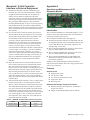
Appendix A
Operation and Maintenance of I/O
Expansion Module
Introduction
The I/O Expansion Module is a field-installed option. It is an
extension of the main board and provides extra functionality
to the MicroTech III control system.
The I/O Expansion Module has 4 main purposes:
■ The MicroTech III unit controller in combination with the
I/O Expansion Module will be the standard control system
for two stage Water Source Heat Pump equipment. For
example: large vertical units.
■ The I/O Expansion Module has outputs to control electric
heat on a standard Water Source Heat Pump.
■ The I/O Expansion Module has outputs for multi-speed
fans on a standard Water Source Heat Pump.
■ The I/O Expansion Module has an independent LED
annunciator to identify operational fault conditions on
second stage equipment.
Adding an I/O Expansion Module (with an interconnect
cable) to the main controller allows two stage operation of the
water source heat pump.
Features
Second Circuit
■ High pressure switch
■ Low pressure switch
■ Low suction line temperature sensor
■ Compressor output
■ Reversing valve
Standard Heat Pumps / Single Circuit Units
■ Monitors entering water temperature for boilerless
electric heat control
■ Outputs for medium and high speed fan controls
Table 5: IV/PR(H8) Terminal and Compressor Operation
IV/PR(H8)
Normally Open
Normally Closed
Compressor On
24 VAC
0 VAC
Compressor Off
0 VAC
24 VAC
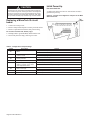
OM 931-3 / Page 15 of 28
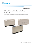
Initial Power up
Figure 8: I/O Expansion Board Configuration Jumper Terminals
Table 6: I/O Expansion Board Configuration Jumper Settings
Jumper
Description
Options
Open for single compressor
JP1
Number of Compressors
Shorted for dual compressor
Open to disable reheat
JP2
Hot Gas/Water Reheat
Shorted to enable reheat
JP3 and JP4 open for no supplemental heat
JP3 & JP4
Supplemental Heat TypeJP3 open, JP4 shorted for boilerless electric heat
JP3 and JP4 shorted is an invalid setting
JP5 and JP6 open for single-speed fan
JP5 open, JP6 shorted for three-speed fan
JP5 & JP6
Fan Speed Selection
JP5 shorted and JP6 open for two-speed fan
JP 5 and JP6 shorted is an invalid setting
Open for single-speed compressor
JP7
Compressor Speed Type
Shorted for two-speed compressor
JP8
Future Spare
Page 16 of 28 / OM 931-3
Operation
Three-Speed Fan Operations
Dual Circuit Units
Table 7: Three-Speed Fan
• Provides standard lead / lag operation for two compressors
in dual circuit units
• Circuit one will come on first when there is any call for
heating or cooling at the main board
• The second circuit will be enabled after the interstage
timer has expired. The interstage timer defaults to 300
seconds
• HP, LP, SLTS fault for either circuit one or circuit two,
will lockout the entire unit and subject for intelligent reset
Thermostat Inputs (Y2, W2)
• The Y2 terminal which is cooling mode stage two,
energizes the second compressor
• If Y1 and Y2 thermostat inputs are active at the same time,
interstage timers will be used to stage the compressor up
and down
• The W2 terminal which is heating mode stage two,
energizes the second reversing valve followed 30 seconds
later by the second compressor
• If W1 and W2 thermostat inputs are active at the
same time, interstage timers will be used to stage the
compressors up and down
Electric Heat Controls
Boilerless Heat Coil Control
• Turns on the factory installed heater when the entering
water temperature is less than 55°F, the temperature set
point is not adjustable
• For geothermal applications the factory installed electric
heater turns on when the entering water temperature is less
than 30°F
Note: In both cases the compressor is shut down.
Multiple Speed Fan Control
• When the Water Source Heat Pump is equipped with an
I/O Expansion Module and factory installed electric heat,
three speed fan control is possible.
• If the thermostat is calling for continuous fan operation
and the compressor is not running the fan motor will run
in low speed.
• If there is a call for heating or cooling (compressor is
running) the fan motor will run in medium speed.
• If the electric heater is enabled the fan motor does not run
in high speed.
Note: On units with an I/O Expansion Module and no electric
heat, it is possible to configure the I/O Expansion
Module for a two speed fan. If there is a call for
continuous fan (compressor off) the fan motor runs
in low speed. If there is a call for heating or cooling
(compressor on) the fan motor runs at high speed.
Continuous Fan Compressor On Electric Heat
Off
Off
Space Temp Satisfied Low Speed
Compressor
Off
Med. Speed
Off
Heating/Cooling High Speed
Off
Off
Electric Heat Enabled
Two-Speed Fan Operations
Table 8: Two-Speed Fan
Continuous Fan Compressor On Electric Heat
Off
Off
Space Temp Satisfied Low Speed
Compressor
Off
High Speed
Off
Heating/Cooling High Speed
Off
Off
Electric Heat Enabled
Circuit Two, Additional Operating
Modes
The I/O Expansion Module controls the second circuit high
pressure, low pressure, and low suction line temperature
operating conditions in the same manner as the main board
controls the first circuit.
Table 9: I/O Expansion Module LED & Fault Outputs
Status LED's
Thermostat Alarm
Light Output
Mode / Fault
YellowGreen Red
Terminal “A”
Invalid Configuration Flash Flash
Jumper Setting Base Board Communication Fail
Off
Off
De-energized
Flash
Flash
N/A
High Pressure #2 Fault
Off
Off
Flash
De-energized
Low Pressure #2 Fault
Off
Off
On
De-energized
Low Suction Temp #2 Fault Flash
Off
Off
De-energized
Sensor Failures Low Suction
Low Suction Temp #2,
1
EWT (w/ Boilerless EH only)
Flash Flash
On
De-energized
Flash Flash
Flash
De-energized
Off
Energized
Occupied, Bypass,
Standby, or Tenant Off
On
Off
Override Modes
Energized
2 Service
Test Mode Enabled
Unoccupied Mode
On
On
Note: Mode / Faults are listed in order of priority.
1
Boilerless electric heat only
2
Alarm/fault LED indications take precedence over
service test mode LED indication. The controller shall
use service test mode if the service test mode jumper
is installed, even if the LED’s indicate an alarm/fault.
OM 931-3 / Page 17 of 28
Second Circuit Faults
With the addition of the second circuit the fault recovery and
reset table has new faults for the second circuit (Table 10).
Table 10: Second Circuit Faults
● = Applies
Fault
Auto Recovery
Invalid Configuration Jumper Setting
–
– = Does not apply
Remote Reset (Tenant Override)
–
Reset (Network
Command or Power)
●
Brownout
●
– ●
HP2
–
●
●
LP1
●*
●
●
LT2 (In Heating)
●*
●
●
LT2 (In Cooling)
–
●
●
–
–
●
Room Temperature, LT1, LT2, Sensor
Failure
EWT(w/Boilerless EH Only)
–
–
●
Condensate Overflow ●
–
●
EEPROM Failure
–
–
–
* Auto Recover for the first two occurrences, lockout on the third occurrence within 24 hours, i.e., subject to “Intelligent Reset.”
Table 11: I/O Expansion Module Connections & Descriptions
H8
Pin 1
Description
Fan high speed normally open output
Pin 2
No connection
Pin 3
24 VAC Common
H3
Pin 1
Pin 2
Pin 3
Pin 4
Pin 5
Pin 6
H8
For future development
Pin 1
Dual compressor: compressor 2 normally
open output, all others fan medium speed
normally open
Pin 2
24 VAC common
Pin 3
No connection
Pin 4
Dual compressor: reversing valve for
circuit 2, all others electric heat
Pin 5
24 VAC common
H4
Pin 1
Entering water temperature sensor signal
Pin 2
Entering water temperature sensor common
HP6
HP2-1
High pressure switch for circuit 2
HP2-2
High pressure switch for circuit 2
H7
Pin 1
Suction line temperature sensor circuit 2 signal
Pin 2
Suction line temperature sensor circuit 2 common
Pin 3
Low pressure switch circuit 2 signal
Pin 4
Low pressure switch circuit 2 source
H5
LED Annunciator
TB1 For future use
Page 18 of 28 / OM 931-3
Appendix B
MicroTech III Unit Controller with
LonWorks® Communication Module
For installation and operation information on LonWorks
Communication Module and other ancillary control components, see:
■ IM 927 - MicroTech III Water Source Heat Pump
LonWorks Communication Module.
■ IM 933 - LonMaker Integration Plug-in Tool: For use with
the MicroTech III Unit Controller.
■ IM 955 - MicroTech III Wall Sensor for use with
Microtech III Unit Controller
Each Daikin McQuay water source heat pump can be
equipped with a LonWorks communication module that is
LonMark 3.4 certified to meet the LonMark Space Comfort Control (SCC) profile for heat pumps. The controller is
microprocessor-based and is designed to communicate over
a LonWorks communications network. It can be factory or
field-installed.
The unit controller is programmed and tested with all the
logic required to monitor and control the unit. An optional
wall sensor may be used with the communication module to
provide limited local control of the Water Source Heat Pump.
The unit controller monitors water and air temperatures and
passes information to the communication module. The module communicates with the BAS, to provide network control
of the Water Source Heat Pump.
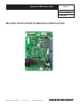
Figure 9: LonWorks Communication Module
MicroTech III Unit Controller with LonWorks Communication Module orchestrates the following unit operations:
Enable heating and cooling to maintain setpoint based on
a room sensor
Enable fan and compressor operation
Monitors all equipment protection controls
Monitors room and discharge air temperatures
Monitors leaving water temperature
Relays status of all vital unit functions
The MicroTech III unit controller with
communication module includes:
■ Return Air Temperature sensor (RAT)(field-installed)
■ Discharge Air Temperature sensor (DAT)(field-installed)
■ Leaving Water Temperature sensor (LWT)
Note: Refer to IM 956-X for details to install (RAT) & (DAT)
sensors.
CAUTION
When an optional wall-mounted room temperature sensor is
connected to the unit controller, the Return Air Temperature
(RAT) sensor must not be installed. A wall-mounted room
temperature sensor and the return air temperature sensor
must not be connected simultaneously or the unit will not
operate properly.
The communication module provides access to setpoints for
operational control
Available wall sensors include:
Room sensor with LED status and tenant override button
Room sensor with LED status, tenant override button, and
±3°F setpoint adjustment
Room sensor with LED status, tenant override
button, 55° to 90°F setpoint adjustment
The MicroTech III unit controller with communication
module includes a unit-mounted return air, discharge air and
leaving water temperature sensor. Wall mounted temperature
sensors include setpoint adjustment and tenant override. The
user has the capability of substituting the wall sensor with a
duct-mounted return air sensor.
OM 931-3 / Page 19 of 28
MicroTech III Controller with BACnet®
Communication Module
For installation and operation information on MicroTech III
unit controller and other ancillary components, see:
■ IM 928 - MicroTech III Water Source Heat Pump BACnet
Communication Module
■ IM 955 - MicroTech III Wall Sensor For use with
Microtech III Unit Controller
Daikin McQuay water source heat pumps are available with
Daikin McQuay BACnet MS/TP communication module that
is designed to communicate over a BACnet MS/TP communications network to a building automation system (BAS). It
can be factory or field-installed.
The unit controller is programmed and tested with all the
logic required to monitor and control the unit. An optional
wall sensor may be used with the communication module to
provide limited local control of the water source heat pump.
The unit controller monitors water and air temperatures and
passes information to the communication module. The module communicates with the BAS, to provide network control
of the water source heat pump.
The module makes operational data and commands available
on a communications network using BACnet objects and
properties:
■ The network cable is a shielded twisted-pair cable
■ Network communications run up to 76.8 Kbps
■ DIP switches on the controller enable the MS/TP MAC
address to be set in the range 0-127
■ Four green status LEDs on the communication module
indicate communication activity on the MS/TP
communication network and with the unit controller
Figure 10: MicroTech III BACnet MS/TP Snap-in
Communication Module
Page 20 of 28 / OM 931-3
MicroTech III Unit Controller with BACnet MS/TP Communication Module orchestrates the following unit operations:
■ Enable heating and cooling to maintain setpoint based on
a room sensor
■ Enable fan and compressor operation
■ Monitors all equipment protection controls
■ Monitors room and discharge air temperatures
■ Monitors leaving water temperature
■ Relays status of all vital unit functions
The MicroTech III unit controller with
communication module includes:
■ Return Air Temperature sensor (RAT)(field-installed)
■ Discharge Air Temperature sensor (DAT)(field-installed)
■ Leaving Water Temperature sensor (LWT)
Note: Refer to IM 956-X for details to install (RAT) & (DAT)
sensors.
CAUTION
When an optional wall-mounted room temperature sensor is
connected to the unit controller, the Return Air Temperature
(RAT) sensor must not be installed. A wall-mounted room
temperature sensor and the return air temperature sensor
must not be connected simultaneously or the unit will not
operate properly.
The communication module provides access to setpoints for
operational control
Available wall sensors include:
■ Room sensor with LED status and tenant override button
■ Room sensor with LED status, tenant override button, and
±3°F setpoint adjustment
■ Room sensor with LED status, tenant override
button, 55° to 90°F setpoint adjustment
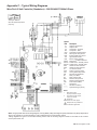
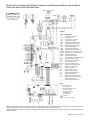
Appendix C – Typical Wiring Diagrams
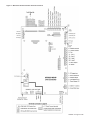
MicroTech III Unit Controller (Standalone) – 208/230/460/575/60Hz/3-Phase
Table B
208V RED
230V ORG
*Drawing No. 668991201
Shown with optional desuperheater
pump wiring.
Legend
ItemDescription
C1
C2
CC
CM
CDS
DAT
EWT
HP
HTR
IOEXP
ISO-NC
ISO-NO
LED1
LED2
LP
SLTS
LWT
MIII
R1
R2
RAT
RV
TB1
X1
_____
_ _ _ _
Capacitor-Compressor
Capacitor-Fan
Compressor - Contactor
Compressor - Motor
Condensate Overflow Sensor
Discharge Air Temp Sensor
Entering Water Temp Sensor
High Pressure Switch
Electric Heater Cartridge
I/O Expansion Board / Harness
Isolation Valve - Normally Closed
Isolation Valve - Normally Open
LED Annunciator / Harness
LED Annunciator / Harness
Low Pressure Switch
Suction Line Temp Sensor
Leaving Water Temp Sensor
MicroTech III Main Board
Relay - Fan Motor
Relay - Electric Heat
Return Air Temp Sensor
Reversing Valve Solenoid
Power Terminal Block
Transformer
Standard Unit Wiring
Optional Wiring (by others)
Notes:
1.
Main board jumpers:
No jumpers shorted. All open.
2.
I/O expansion board jumpers:
Jumper JP4 shorted.
Transformer:
Unused wire to be capped.
Desuperheater only available on
115-208-230V applications.
Note: The gray tinted areas in the wiring diagram; Leaving Water (LWT), Discharge Air (DAT) and Return Air (RAT) Temperature
sensors are shipped or are field installed on units configured with a communication module.
*Wiring diagrams are typical. For the latest drawing version refer to the wiring diagram located on the inside of the controls
access panel of the unit.
OM 931-3 / Page 21 of 28
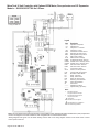
MicroTech III Unit Controller with Optional ECM Motor, Desuperheater and I/O Expansion
Module – 208/230/265/277/60 Hz/1-Phase
Table B
208V RED
230V ORG
265V BRN
277V BRN
*Drawing No. 668991501
Legend
ItemDescription
C1
C2
CC
CM
CDS
DAT
EWT
HP
HTR
IOEXP
ISO-NC
ISO-NO
LED1
LED2
LP
SLTS
LWT
MIII
R1
R2
RAT
RV
TB1
X1
_____
_ _ _ _
Capacitor-Compressor
Capacitor-Fan
Compressor - Contactor
Compressor - Motor
Condensate Overflow Sensor
Discharge Air Temp Sensor
Entering Water Temp Sensor
High Pressure Switch
Electric Heater Cartridge
I/O Expansion Board / Harness
Isolation Valve - Normally Closed
Isolation Valve - Normally Open
LED Annunciator / Harness
LED Annunciator / Harness
Low Pressure Switch
Suction Line Temp Sensor
Leaving Water Temp Sensor
MicroTech III Main Board
Relay - Fan Motor
Relay - Electric Heat
Return Air Temp Sensor
Reversing Valve Solenoid
Power Terminal Block
Transformer
Standard Unit Wiring
Optional Wiring (by others)
Notes:
1.
Main board jumpers:
No jumpers shorted. All open.
2.
I/O expansion board jumpers:
Jumper JP4 shorted.
Transformer:
Unused wire to be capped.
Desuperheater only available on
115-208-230V applications.
Note: The gray tinted areas in the wiring diagram; Leaving Water (LWT), Discharge Air (DAT) and Return Air (RAT) Temperature
sensors are shipped or are field installed on units configured with a communication module.
*Wiring diagrams are typical. For the latest drawing version refer to the wiring diagram located on the inside of the controls
access panel of the unit.
Page 22 of 28 / OM 931-3
MicroTech III Unit Controller with Optional ECM Motor, Desuperheater, Electric Heat Coil
and I/O Expansion Module – 208/230/460/60 Hz/3-Phase
Table B
208V RED
230V ORG
460V BLK/RED
*Drawing No. 668991301
Legend
ItemDescription
C1
C2
CC
CM
CDS
DAT
EWT
HP
HTR
IOEXP
ISO-NC
ISO-NO
LED1
LED2
LP
SLTS
LWT
MIII
R1
R2
RAT
RV
TB1
X1
_____
_ _ _ _
Capacitor-Compressor
Capacitor-Fan
Compressor - Contactor
Compressor - Motor
Condensate Overflow Sensor
Discharge Air Temp Sensor
Entering Water Temp Sensor
High Pressure Switch
Electric Heater Cartridge
I/O Expansion Board / Harness
Isolation Valve - Normally Closed
Isolation Valve - Normally Open
LED Annunciator / Harness
LED Annunciator / Harness
Low Pressure Switch
Suction Line Temp Sensor
Leaving Water Temp Sensor
MicroTech III Main Board
Relay - Fan Motor
Relay - Electric Heat
Return Air Temp Sensor
Reversing Valve Solenoid
Power Terminal Block
Transformer
Standard Unit Wiring
Optional Wiring (by others)
Notes:
1.
Main board jumpers:
No jumpers shorted. All open.
2.
I/O expansion board jumpers:
Jumper JP4 shorted.
Transformer:
Unused wire to be capped.
Desuperheater only available on
115-208-230V applications.
Note: The gray tinted areas in the wiring diagram; Leaving Water (LWT), Discharge Air (DAT) and Return Air (RAT) Temperature
sensors are shipped or are field installed on units configured with a communication module.
*Wiring diagrams are typical. For the latest drawing version refer to the wiring diagram located on the inside of the controls access
panel of the unit.
OM 931-3 / Page 23 of 28
MicroTech III Unit Controller with Optional ECM Motor, Desuperheater, and I/O Expansion
Module 208/230/460/60/3-Phase
Table B
208V RED
230V ORG
460V BLK/RED
*Drawing No. 668991401
Legend
ItemDescription
C1
C2
CC
CM
CDS
DAT
EWT
HP
HTR
IOEXP
ISO-NC
ISO-NO
LED1
LED2
LP
SLTS
LWT
MIII
R1
R2
RAT
RV
TB1
X1
_____
_ _ _ _
Capacitor-Compressor
Capacitor-Fan
Compressor - Contactor
Compressor - Motor
Condensate Overflow Sensor
Discharge Air Temp Sensor
Entering Water Temp Sensor
High Pressure Switch
Electric Heater Cartridge
I/O Expansion Board / Harness
Isolation Valve - Normally Closed
Isolation Valve - Normally Open
LED Annunciator / Harness
LED Annunciator / Harness
Low Pressure Switch
Suction Line Temp Sensor
Leaving Water Temp Sensor
MicroTech III Main Board
Relay - Fan Motor
Relay - Electric Heat
Return Air Temp Sensor
Reversing Valve Solenoid
Power Terminal Block
Transformer
Standard Unit Wiring
Optional Wiring (by others)
Notes:
1.
Main board jumpers:
No jumpers shorted. All open.
2.
I/O expansion board jumpers:
Jumper JP4 shorted.
Transformer:
Unused wire to be capped.
Desuperheater only available on
115-208-230V applications.
Note: The gray tinted areas in the wiring diagram; Leaving Water (LWT), Discharge Air (DAT) and Return Air (RAT) Temperature
sensors are shipped or are field installed on units configured with a communication module.
*Wiring diagrams are typical. For the latest drawing version refer to the wiring diagram located on the inside of the controls
access panel of the unit.
Page 24 of 28 / OM 931-3
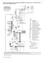
MicroTech III Unit Controller with PSC Motor, Desuperheater and I/O Expansion Module for Hot Gas Reheat
Control (Unit Sizes 019-070) 208/230/60/1-Phase
Table B
208V RED
230V ORG
*Drawing No. 669007101A
Legend
ItemDescription
C1
C2
CC
CM
COS
DAT
EWT
HP
HTR
IOEXP
ISO-NC
ISO-NO
DSHP
HGRH
P1
LED1
LED2
LP
SLTS
LWT
MIII
R1
R2
RAT
RV
TB1
X1
X2
_____
_ _ _ _
Capacitor-Compressor
Capacitor-Fan
Compressor - Contactor
Compressor - Motor
Condensate Overflow Sensor
Discharge Air Temp Sensor
Entering Water Temp Sensor
High Pressure Switch
Electric Heater Cartridge
I/O Expansion Board / Harness
Isolation Valve - Normally Closed
Isolation Valve - Normally Open
Desuperheater Pump
3-Way Valve Solenoid
24 VAC Supply I/O Expansion Brd.
LED Annunciator / Harness
LED Annunciator / Harness
Low Pressure Switch
Suction Line Temp Sensor
Leaving Water Temp Sensor
MicroTech III Main Board
Relay - Fan Motor
Relay - Electric Heat
Return Air Temp Sensor
Reversing Valve Solenoid
Power Terminal Block
Primary 24 VAC Transformer
Secondary 24 VAC Transformer
Standard Unit Wiring
Optional Wiring (by others)
Notes:
1.
Main Board Jumpers:
JP3 Geothermal.
2.
I/O Expansion Board Jumpers:
JP4 Hot Gas Reheat.
JP3 Supplemental EH.
JP4 Boilerless EH.
JP5 2-Speed Fan
Transformer:
Unused wire to be capped.
Note: The gray tinted areas in the wiring diagram; Leaving Water (LWT), Discharge Air (DAT) and Return Air (RAT) Temperature
sensors are shipped or are field installed on units configured with a communication module.
*Wiring diagrams are typical. For the latest drawing version refer to the wiring diagram located on the inside of the controls access
panel of the unit.
OM 931-3 / Page 25 of 28
Controller Comparison
Note: The Mark IV, MicroTech 2000, Alerton and MicroTech III boards are NOT interchangeable.
Table 12: Control Boards and Features
● = Applies
Mark IV
MicroTech 2000 Alerton
– = Does not apply
MicroTech III
Features
DC Power
●
–
–
–
AC Power
●
● ●
●
Terminal Connection 1/4″ Push-on ●
–
–
–
IDC Connection
–
●
●
●
Fault Indicators
●
●
–
●
Thermostatic Controls
●
–
–
●
Room Sensor
–
●
●
●
LONmark Capable
–
●
–
●
LonWorks Capable
–
●
–
–
BACnet Capable(1)
–
–
●
●
Motorized Valve Capability
–
●
●
●
Short Cycle Protection & Random Start
●
●
●
●
Unoccupied Mode
●
●
●
●
Override Mode
●
●
●
●
Pump Restart
●
●
●
●
Loadshed
●
●
●
–
Brownout Protection
●
●
●
●
Unit Shutdown
●
●
●
●
Condensate Overflow Protection
●
●
●
●
Remote Reset(1)
●
–
–
●
Reset(1)
Intelligent
–
–
–
●
Dual Circuit Capability
●
●
●
●
Adjustable Set Points Through Software
–
●
●
●
Adjustable Fan Speed
–
–
–
●
Electric Heat Availability
–
–
–
●
Service Tools Needed at Start up
–
●
●
●
Dipswitch Settings
–
–
●
–
Programmable Front-end Settings
–
●
–
●
Switching Line Voltage
●
–
–
●
Note:
(1) Alerton BACnet requires Alerton service tools for commissioning
(1) Alerton dipswitch settings must be configured during commissioning
(1) See Remote Reset and Intelligent Reset information under section: Additional Operating Modes
Page 26 of 28 / OM 931-3
This page left blank intentionally
OM 931-3 / Page 27 of 28
Daikin McQuay Training and Development
Now that you have made an investment in modern, efficient Daikin McQuay equipment, its care should
be a high priority. For training information on all Daikin McQuay HVAC products, please visit us at www.
daikinmcquay.com and click on Training, or call 540-248-9646 and ask for the Training Department.
Warranty
All Daikin McQuay equipment is sold pursuant to its standard terms and conditions of sale, including
Limited Product Warranty. Consult your local Daikin McQuay Representative for warranty details. Refer
to Form 933-430285Y. To find your local Daikin McQuay Representative, go to www.daikinmcquay.com.
Aftermarket Services
To find your local parts office, visit www.daikinmcquay.com or call 800-37PARTS (800-377-2787). To find
your local service office, visit www.daikinmcquay.com or call 800-432-1342.
This document contains the most current product information as of this printing. For the most up-to-date
product information, please go to www.daikinmcquay.com.
Products manufactured in an ISO certified facility.
©2012 McQuay International • www.daikinmcquay.com • 800.432.1342
OM 931-3 Page 28 of 28 (5/12)